HPT 1000 CAN Druckmessumformer - Pressure transmitter - HYDAC
←
→
Transkription von Seiteninhalten
Wenn Ihr Browser die Seite nicht korrekt rendert, bitte, lesen Sie den Inhalt der Seite unten
Druckmessumformer
                           Pressure transmitter

                           HPT 1000 CAN
                           CANopen
Bedienungsanleitung
(Originalanleitung)
                           SAEJ1939
Instruction manual
(Translation of original

instructions)
                                                  Mat –Nr. 670023/ Stand: 08.05.2020 D/E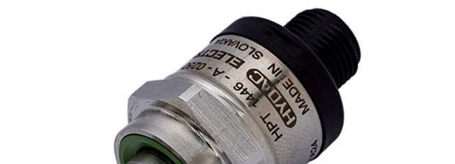
2                                                                                                                 HPT 1000 CAN

    Inhalt

D   1

    1.1
            Allgemeine Hinweise .............................................................................................. 4

            Haftungsausschluss .................................................................................................. 4

    1.2     Gewährleistung ......................................................................................................... 4

    2       Beschreibung .......................................................................................................... 5

    3       Montage ................................................................................................................... 5

    4       Anschlussbelegung ................................................................................................ 6

    5       Protokolldaten ......................................................................................................... 6

    5.1     CANopen .................................................................................................................. 6

    5.2     SAE J1939 ................................................................................................................ 6

    6       Parametrierung........................................................................................................ 7

    6.1     Parametrierung mit HYDAC Handmessgerät HMG 4000.......................................... 7

    7       Technische Daten ................................................................................................... 8

    8       Bestellangaben........................................................................................................ 9

    9       Abmessungen ....................................................................................................... 10

    10      Zubehör .................................................................................................................. 11

    11      Kontakt ................................................................................................................... 12

    Stand: 08.05.2020                          HYDAC ELECTRONIC GMBH                                                 Mat. Nr.: 670023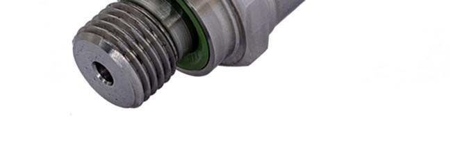
HPT 1000 CAN                                                                              3

 Vorwort

                    Für Sie, den Benutzer unseres Produktes, haben wir in dieser

                                                                                               D
                    Dokumentation die wichtigsten Hinweise zum Bedienen und Warten
                    zusammengestellt.

                    Sie dient Ihnen dazu, das Produkt kennen zu lernen und seine
                    bestimmungsgemäßen Einsatzmöglichkeiten optimal zu nutzen.

                    Diese Dokumentation muss ständig am Einsatzort verfügbar sein.
                    Bitte beachten Sie, dass die in dieser Dokumentation gemachten Angaben
                    der Gerätetechnik zu dem Zeitpunkt der Literaturerstellung entsprechen.
                    Abweichungen bei technischen Angaben, Abbildungen und Maßen sind
                    deshalb möglich.

                    Entdecken Sie beim Lesen dieser Dokumentation Fehler oder haben
                    weitere Anregungen und Hinweise, so wenden Sie sich bitte an:

                    HYDAC ELECTRONIC GMBH
                    Technische Dokumentation
                    Hauptstraße 27
                    66128 Saarbrücken
                    -Deutschland-
                    Tel:   +49(0)6897 / 509-01
                    Fax: +49(0)6897 / 509-1726
                    Email: electronic@hydac.com

                    Die Redaktion freut sich über Ihre Mitarbeit.

                    „Aus der Praxis für die Praxis“

Stand: 08.05.2020              HYDAC ELECTRONIC GMBH                        Mat. Nr.: 670023
4                                                                              HPT 1000 CAN
    1 Allgemeine Hinweise
    Die Drucksensoren der Serie HPT 1000 CAN werden einzeln auf rechnergesteuerten
    Prüfplätzen abgeglichen und einem Endtest unterzogen. Sie sind wartungsfrei und arbeiten
    beim Einsatz innerhalb der Spezifikationen (siehe Technische Daten) einwandfrei.

D
    Falls trotzdem Fehler auftreten, wenden Sie sich bitte an den HYDAC-Service.
    Fremdeingriffe in das Gerät führen zum Erlöschen jeglicher Gewährleistungsansprüche.

                        Überprüfen Sie vor der Inbetriebnahme den Zustand des Gerätes sowie
                        des mitgelieferten Zubehörs. Lesen Sie vor der Inbetriebnahme des
                        Gerätes die Bedienungsanleitung und stellen Sie sicher, dass das Gerät
                        für Ihre Anwendung geeignet ist.

                        Falsche Handhabung bzw. die Nichteinhaltung von Gebrauchshinweisen
                        oder technischen Angaben kann zu Sach- und / oder Personenschäden
                        führen.

    1.1 Haftungsausschluss
    Diese Bedienungsanleitung haben wir nach bestem Wissen und Gewissen erstellt. Es ist
    dennoch nicht auszuschließen, dass trotz größter Sorgfalt sich Fehler eingeschlichen haben
    könnten. Haben Sie bitte deshalb Verständnis dafür, dass wir, soweit sich nachstehend nichts
    anderes ergibt, unsere Gewährleistung und Haftung - gleich aus welchen Rechtsgründen -
    für die Angaben in dieser Bedienungsanleitung ausschließen. Insbesondere haften wir nicht
    für entgangenen Gewinn oder sonstige Vermögensschäden. Dieser Haftungsausschluss gilt
    nicht bei Vorsatz und grober Fahrlässigkeit. Er gilt ferner nicht für Mängel, die arglistig
    verschwiegen wurden oder deren Abwesenheit garantiert wurde, sowie bei schuldhafter
    Verletzung von Leben, Körper und Gesundheit. Sofern wir fahrlässig eine
    vertragswesentliche Pflicht verletzen, ist unsere Haftung auf den vorhersehbaren Schaden
    begrenzt. Ansprüche aus Produkthaftung bleiben unberührt.

    Im Falle der Übersetzung ist der Text der deutschen Originalbedienungsanleitung der allein
    gültige.

    1.2 Gewährleistung
    Grundsätzlich gelten die „Allgemeinen Geschäftsbedingungen“ der Firma HYDAC
    ELECTRONIC GMBH. Diese stehen dem Betreiber spätestens mit der Auftragsbestätigung
    bzw. mit dem Vertragsabschluss zur Verfügung.
    Sie finden diese auch unter www.hydac.com -> Allgemeine Geschäftsbedingungen (AGB)

    Stand: 08.05.2020                HYDAC ELECTRONIC GMBH                        Mat. Nr.: 670023
HPT 1000 CAN 5
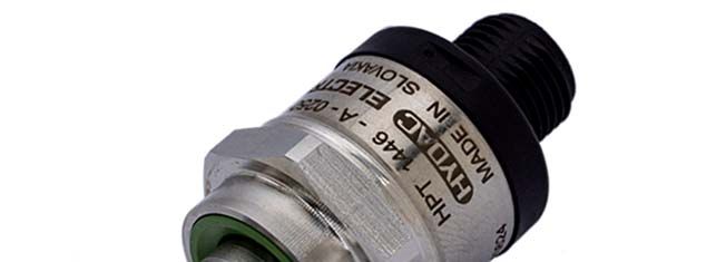
2 Beschreibung
Der HPT 1000 CAN ist ein digitaler Druckmessumformer zur Erfassung von Relativdrücken
in der Hydraulik und Pneumtik. Der erfasste Druckwert wird digitalisiert und über das
CANopen-Protokoll oder J1939-Protokoll dem CAN-Feldbussystem zur Verfügung gestellt.
D
Für den Anwender sind die Geräteparameter mit handelsüblicher CAN-Software einsehbar
und konfigurierbar.
Die auf Basis der Baureihe HPT 1000 entwickelten Druckmessumformer verfügen über eine
sehr genaue und robuste Sensorzelle mit einer Dünnfilm-DMS auf einer Edelstahlmembran.
Durch zudem herausragende Temperatur- und EMV-Eigenschaften, sowie die sehr kleine,
kompakte Bauform sind diese Geräteserien in einem breiten Anwendungsfeld im mobilen
oder industriellen Bereich einsetzbar.
3 Montage
Der Drucksensor kann über den Gewindeanschluss direkt an der Hydraulikanlage montiert
werden. Um in kritischen Anwendungsfällen (z.B. starke Vibrationen oder Schläge) einer
mechanischen Zerstörung vorzubeugen, empfehlen wir das Gerät mittels einer Schelle mit
Elastomereinsatz zu befestigen, sowie den Hydraulikanschluss über eine Minimess-Leitung
zu entkoppeln. Die empfohlene Einbaulage für hydraulische Anwendungen ist senkrecht mit
dem Druckanschluss nach oben, für pneumatische Anwendungen senkrecht mit dem
Druckanschluss nach unten. Der elektrische Anschluss sollte von einem Fachmann nach den
jeweiligen Landesvorschriften durchgeführt werden (VDE 0100 in Deutschland).
Die Drucksensoren der Serie HPT 1000 CAN tragen das - Zeichen. Eine
Konformitätserklärung ist auf Anfrage erhältlich. Die EMV-Normen: EN 61000-6-1, EN 61000-
6-2, EN 61000-6-3 und EN 61000-6-4 werden erfüllt. Die Forderungen der Normen werden
nur bei ordnungsgemäßer und fachmännischer Erdung des Sensorgehäuses erreicht. Beim
Einschrauben in einen Hydraulikblock ist es ausreichend, wenn der Block über das
Hydrauliksystem geerdet ist. Bei einer Schlauchmontage muss das Gehäuse separat geerdet
werden.
Zusätzliche Montagehinweise, die erfahrungsgemäß den Einfluss elektromagnetischer
Störungen reduzieren:
Möglichst kurze Leitungsverbindungen herstellen
Der Kabelschirm ist in Abhängigkeit der Umgebungsbedingungen fachmännisch und zum
Zweck der Störunterdrückung einzusetzen
Direkte Nähe zu Verbindungsleitungen von Leistungsverbrauchern oder störenden Elektro-
oder Elektronikgeräten ist möglichst zu vermeiden
Stand: 08.05.2020 HYDAC ELECTRONIC GMBH Mat. Nr.: 6700236 HPT 1000 CAN
4 Anschlussbelegung
M12x1 Pin Signal Beschreibung
1 PE shield/housing
D
2 +UB supply +
3 0V supply -
4 CAN_H bus line dominant high
5 CAN_L bus line dominant low
Belegung gemäß CIA-DR-303-1
Stecker DT-04, 4-pol Pin Signal Beschreibung
1 +UB supply +
2 0V supply -
3 CAN_H bus line dominant high
4 CAN_L bus line dominant low
5 Protokolldaten
5.1 CANopen
Communication Profile CiA DS 301 V4.2
Device Profile CiA DS 404 V1.3
Layer Setting Services and CiA DSP 305 V3.0
Protocol
Baudraten 10 kbit .. 1 Mbit gem. DS305 V3.0
Übertragungsdienste
- PDO Messwert als 16bit integer /
- Transfer 32bit integer oder 32bit float; Status
synchron, asynchron, zyklisch,
Messwertänderung, Bereichsgrenzenüberschreitung
Node Id/Baudrate einstellbar über Manufacturer Specific Profile
Voreinstellung: Baudrate: 250 kbit
Node Id: 1
Weitere Informationen entnehmen Sie bitte der: “Protokoll-Beschreibung CANopen HPT 1000“
5.2 SAE J1939
Data Link Layer SAE J1939-21
Network Layer SAE J1939-31
Network Management SAE J1939-81
Voreinstellungen:
CAN Daten Quelladresse 1
Baudrate 250 kBit
Übertragungsrate [ms] 100
Datenlänge [Bytes] 8
Priorität 6
PDU format 255
PDU specific 0
Weitere Informationen entnehmen Sie bitte der: “Protokoll-Beschreibung J1939 HPT 1000“
Stand: 08.05.2020 HYDAC ELECTRONIC GMBH Mat. Nr.: 670023HPT 1000 CAN 7
6 Parametrierung
6.1 Allgemeines
Zur Inbetriebnahme des Sensors wird eine elektronische Gerätebeschreibungsdatei benötigt,
D
die sogenannte „EDS“-Datei (Electronic Data Sheet)
Die EDS-Datei und die entsprechende Protokollbeschreibung finden Sie zum Download auf
unserer Homepage unter:
→Produkte→Sensorik→Produktsuche
http://www.hydac.com/de-de/produkte/sensorik/show/Material/index.html
Bei Eingabe der Materialnummer (9xxxxx) erscheint das entsprechende ZIP-file, welches die
EDS-Dateien und die Protokollbeschreibung enthält.
6.2 Parametrierung mit HYDAC Handmessgerät HMG 4000
Schließen Sie den CAN-Sensor mit Standardkabel über die rote Buchse „CAN“ (K) ohne
externen Abschlusswiderstand am HMG 4000 an.
Nach dem Einlesen der EDS-Datei in den Dateimanager können Sie mit Hilfe des
Gerätekonfigurationsassistenten die Knoten-ID bzw. Adresse und Baudrate von CANopen-
bzw. J1939-Geräten der HYDAC ELECTRONIC GMBH konfigurieren.
Die Betriebsdaten des CAN-Sensors werden über die Einträge des Objektverzeichnisses
bereitgestellt.
Nähere Informationen entnehmen Sie bitte der HMG 4000 Bedienungsanleitung
Stand: 08.05.2020 HYDAC ELECTRONIC GMBH Mat. Nr.: 6700238 HPT 1000 CAN
7 Technische Daten
Eingangskenngrößen
Messbereich 1) bar 16 25 40 60 100 250 400 600
Überlastbereich bar 32 50 80 120 200 500 800 1000
Berstdruck bar 125 125 200 300 500 1250 2000 2000
D
Messbereiche psi 500 1000 3000 6000 9000
Überlastbereich psi 1160 2900 7250 11600 14500
Berstdruck psi 2900 7250 14500 29000 29000
Mechanischer Anschluss 2) G 1/4 A ISO 1179-2 Außengewinde
9/16-18 UNF 2A (SAE 6) Außengewinde
jeweils mit Düse
Anzugsdrehmoment, empfohlen 20 Nm [15 lb-ft]
Medienberührende Teile Anschlussstück: Edelstahl
Dichtung: FKM
Ausgangsgrößen HPT 1400 HPT 1700
Ausgangssignal CANopen Protokoll oder J1939 Protokoll, je nach Ausführung
Genauigkeit nach DIN16086 ± 0,5 % FS typ. ± 0,25 % FS typ.
Grenzpunkteinstellung ± 1,0 % FS max. ± 0,5 % FS max.
Genauigkeit bei Kleinstwerteinstellung ± 0,25 % FS typ. ± 0,15 % FS typ.
(B.F.S.L.) ± 0,5 % FS max. ± 0,25 % FS max.
± 0,015 % FS / °C typ. ± 0,008 % FS / °C typ.
Temperaturkompensation Nullpunkt
± 0,025 % FS / °C max. ± 0,015 % FS /°C max.
± 0,015 % FS / °C typ. ± 0,008 % FS / °C typ.
Temperaturkompensation Spanne
± 0,025 % FS / °C max. ± 0,015 % FS /°C max.
Nicht-Linearität bei Grenzpunkteinstellung ± 0,3 % FS max
nach DIN 16086
Hysterese ± 0,4 % FS max. ± 0,1 % FS max.
Wiederholbarkeit ± 0,1 % FS max. ± 0,08 % FS max.
Anstiegszeit 1 ms
Langzeitdrift ± 0,3 % FS typ. / Jahr ± 0,1 % FS typ. / Jahr
Umgebungsbedingungen
Kompensierter Temperaturbereich -25 .. +85 °C [-13 .. +185 °F]
Betriebstemperaturbereich 3) -40 .. +100 °C / -25 .. +85 °C [-40 .. +212 °F / -13 .. 212 °F]
Lagertemperaturbereich -40 .. +100 °C [-40 .. +212 °F]
Mediumstemperaturbereich 3) -40 .. +125 °C / -25 .. 125 °C [-40 .. +257 °F / -13 .. +257 °F]
- Zeichen EN 61000-6-1 / -2 / -3 / -4
- Zeichen E13*10R05/01*/14850*00
Vibrationsbeständigkeit nach 25 g
DIN EN 60068-2-6 bei 10 .. 500Hz
Schockbelastbarkeit nach 100 g / 6 ms / Halbsinus
DIN EN 60068-2-27 500 g / 1 ms / Halbsinus
Schutzart ach DIN EN 60529 4) IP 67
Sonstige Größen
Versorgungsspannung 9 .. 35 V DC
Restwelligkeit Versorgungsspannung ≤5%
Stromaufnahme 3-Leiter 25 mA
Lebensdauer >10 Millionen Lastwechsel (0 .. 100 % FS)
Gewicht: ~ 45 g
Anm.: Verpolungsschutz der Versorgungsspannung, Überspannungs-, Übersteuerungsschutz,
Lastkurzschlussfestigkeit sind vorhanden.
FS (Full Scale) = bezogen auf den vollen Messbereich
1) andere Messbereiche auf Anfrage
2) andere Gewinde auf Anfrage
3) Im Standard bis - 25 °C mit FKM-Dichtung, - 40 °C auf Anfrage
4) bei montierter Kupplungsdose entsprechender Schutzart, Anzugsdrehmoment beachten
Stand: 08.05.2020 HYDAC ELECTRONIC GMBH Mat. Nr.: 670023HPT 1000 CAN 9
8 Bestellangaben
HPT 1 X X X – FXX - XXXXX – 000
Genauigkeit
D
4 = 1 % FS max.
7 = 0,5% FS max.
Anschlussart mechanisch
4 = G 1/4 A ISO 1179-2 Außengewinde, mit Düse
7 = 9/16-18 UNF 2A (SAE 6) Außengewinde, mit Düse
(nur für Druckbereiche in psi)
Anschlussart elektrisch
8 = M12x1, 5-pol.
V = Gerätestecker Deutsch DT-04, 4-pol.
Ausgang
F11 = CANopen
F12 = CAN SAE J1939
Druckbereiche
In bar (vierstellig) 0016; 0025; 0040; 0060; 0100; 0160; 0250; 0400; 0600
In psi (fünfstellig) 00500; 01000; 03000; 06000; 09000 (nur mech. Anschlussart „7“)
Modifikationsnummer
000= Standard
Anmerkung:
Bei Geräten mit anderer Modifikationsnummer ist das Typenschild bzw. die mitgelieferte
technische Änderungsbeschreibung zu beachten.
Stand: 08.05.2020 HYDAC ELECTRONIC GMBH Mat. Nr.: 67002310 HPT 1000 CAN
9 Abmessungen
D
Gerätestecker
M12x1 - 5p
Gerätestecker
M12x1 - 5p
Stand: 08.05.2020 HYDAC ELECTRONIC GMBH Mat. Nr.: 670023HPT 1000 CAN 11
10 Zubehör
ZBE 08 (5-pol.)
Kupplungsdose
D
M12x1, abgewinkelt
Material-Nr.: 6006786
ZBE 08-02 (5-pol.)
Kupplungsdose
M12x1, abgewinkelt
mit 2m Leitung,
Material-Nr.: 6006792
ZBE 08-05 (5-pol.),
Kupplungsdose
M12x1, abgewinkelt
Farbkennung: Pin 1: braun
mit 5m Leitung Pin 2: weiß
Material-Nr.: 6006791 Pin 3: blau
Pin 4: schwarz
Pin 5: grau
ZBE 08S-02 (5-pol.)
Kupplungsdose
M12x1, abgewinkelt
mit 2m Leitung,
geschirmt
Material-Nr.: 6019455
ZBE 08S-05 (5-pol.),
Kupplungsdose
Farbkennung: Pin 1: braun
M12x1, abgewinkelt Pin 2: weiß
mit 5m Leitung, Pin 3: blau
geschirmt Pin 4: schwarz
Material-Nr.: 6019456 Pin 5: grau
ZBE 08S-010 (5-pol.),
Kupplungsdose
M12x1, abgewinkelt
mit 5m Leitung,
geschirmt
Material-Nr.: 6023102
Stand: 08.05.2020 HYDAC ELECTRONIC GMBH Mat. Nr.: 67002312 HPT 1000 CAN
11 Kontakt
D
HYDAC ELECTRONIC GMBH
Hauptstr. 27
D-66128 Saarbrücken
Germany
Web: www.hydac.com
E-Mail: electronic@hydac.com
Tel.: +49 (0)6897 509-01
Fax.: +49 (0)6897 509-1726
HYDAC Service
Für Fragen zu Reparaturen steht Ihnen die HYDAC SYSTEMS & SERVICES zur Verfügung.
HYDAC SYSTEMS & SERVICES GMBH
Hauptstr. 27
D-66128 Saarbrücken
Germany
Tel.: +49 (0)6897 509-1936
Fax.: +49 (0)6897 509-1933
Anmerkung
Die Angaben in dieser Bedienungsanleitung beziehen sich auf die beschriebenen
Betriebsbedingungen und Einsatzfälle. Bei abweichenden Einsatzfällen und/oder
Betriebsbedingungen wenden Sie sich bitte an die entsprechende Fachabteilung.
Bei technischen Fragen, Hinweisen oder Störungen nehmen Sie bitte Kontakt mit Ihrer
HYDAC-Vertretung auf.
Stand: 08.05.2020 HYDAC ELECTRONIC GMBH Mat. Nr.: 670023Pressure transmitter
HPT 1000 CAN
CANopen
SAEJ1939
Instruction manual
(Translation of original
instructions)
Part no.: 670023/ Edition: 2020-05-08 E2 HPT 1000 CAN
Contents
1 General information ................................................................................................ 4
1.1 Exclusion of liability ................................................................................................... 4
1.2 Warranty ................................................................................................................... 4
E
2 Description .............................................................................................................. 5
3 Assembly ................................................................................................................. 5
4 PIN connection ........................................................................................................ 6
5 Protocol Data ........................................................................................................... 6
5.1 CANopen .................................................................................................................. 6
5.2 SAE J1939 ................................................................................................................ 6
6 Parameterisation ..................................................................................................... 7
6.1 Parameterisation with HYDAC portable measuring unit HMG 4000.......................... 7
7 Technical details ..................................................................................................... 8
8 Order details ............................................................................................................ 9
9 Dimensions ............................................................................................................ 10
10 Accessories ........................................................................................................... 11
11 Contact ................................................................................................................... 12
Edition: 2020-05-08 HYDAC ELECTRONIC GMBH Part No.: 670023HPT 1000 CAN 3
Preface
This manual provides you, as user of our product, with key information on
the operation and maintenance of the equipment.
It will acquaint you with the product and assist you in obtaining maximum
benefit in the applications for which it is designed.
E
This documentation must always be kept at hand.
Please note: The specifications given in this documentation regarding the
instrument technology were correct at the time of publishing.
Modifications to technical specifications, illustrations and dimensions are
therefore possible.
If you discover errors while reading the documentation or have additional
suggestions or tips, please contact us at:
HYDAC ELECTRONIC GMBH
Technical Documentation
Hauptstr. 27
66128 Saarbruecken
-Germany-
Phone: +49(0)6897 / 509-01
Fax: +49(0)6897 / 509-1726
Email: electronic@hydac.com
We look forward to receiving your input.
“Putting experience into practice”
Edition: 2020-05-08 HYDAC ELECTRONIC GMBH Part no.: 6700234 HPT 1000 CAN
1 General information
The pressure sensors of the HPT 1000 CAN series are individually subjected to calibration
and final testing on computer operated test stations. They are maintenance-free and operate
perfectly when used according to the specifications (see Technical Data).
However, if there is a cause for complaint, please contact HYDAC Service.
Interference by anyone other than HYDAC personnel will invalidate all warranty claims.
Before commissioning, check the instrument and any accessories
supplied. Before commissioning, please read the operating instructions.
Ensure that the unit is suitable for your application.
E
If the instrument is not handled correctly, or if the operating instructions
and specifications are not adhered to, damage to property or personal
injury can result.
1.1 Exclusion of liability
This instruction manual was made to the best of our knowledge. Nevertheless and despite
the greatest care, it is possible that they may contain errors. Therefore please understand
that in the absence of any provisions to the contrary hereinafter our warranty and liability –
for any legal reasons whatsoever – are excluded in respect of the information in this operating
manual. In particular, we shall not be liable for lost profit or other financial loss. This exclusion
of liability does not apply in cases of intent and gross negligence. Moreover, it does not apply
to defects which have been deceitfully concealed or whose absence has been guaranteed,
nor in cases of culpable harm to life, physical injury and damage to health. If we negligently
breach any material contractual obligation, our liability shall be limited to foreseeable damage.
Claims due to the Product Liability shall remain unaffected.
In the event of translation, only the original version of the operating manual in German is
legally valid.
1.2 Warranty
The General Terms and Conditions ("Allgemeine Geschäftsbedingungen") of HYDAC
ELECTRONIC GMBH always apply. These are available to the operator with the order
confirmation or when the contract is concluded at the latest.
You will also find these under www.hydac.com -> General Terms and Conditions.
Edition: 2020-05-08 HYDAC ELECTRONIC GMBH Part No.: 670023HPT 1000 CAN 5
2 Description
The HPT 1000 CAN is a digital pressure transmitter which is used to measure relative
pressures in hydraulics and pneumatics. The measured pressure value is digitised and made
available to the CAN field bus system via the CANopen protocol or the J1939 protocol. The
instrument parameters can be viewed and configured by the user via standard CAN software.
This pressure transmitter, based on the HPT 1000, has a very accurate and robust sensor
cell with a thin-film strain gauge on a stainless steel membrane. Due to their outstanding
temperature and EMC characteristics, together with their compact dimensions, these device
series can be used in a wide range of applications in the mobile and industrial sectors.
3 Assembly
E
The pressure sensor can be installed directly into the hydraulic system via the threaded
connection. In order to prevent mechanical damage when dealing with critical applications
involving heavy vibrations or blows, for example, we recommend securing the unit with an
elastomer clamp and decoupling the hydraulic ports via a Minimess hose. The recommended
mounting position is vertical with the pressure connection pointing upwards in hydraulic
applications, in pneumatic applications, the pressure connection must point downwards. The
electrical connection must be carried out by a qualified electrician according to the relevant
regulations of the country concerned (VDE 0100 in Germany).
The pressure sensors of the HPT 1000 CAN series are marked. A declaration of conformity
is available on request. The relevant EMC standards EN 61000-6-1; EN 61000-6-2, EN
61000-6-3, EN 6100-6-4 are met. However, the stipulations of those standards are met only
if the sensor's housing has been correctly earthed by a qualified electrician. When fitted into
a hydraulic block, earthing the block via the hydraulic system is sufficient. When using hose
mounting the housing has to be grounded separately.
Additional installation suggestions which, from experience, reduce the effect of
electromagnetic interference:
Make line connections as short as possible.
The cable screening must be fitted by qualified personnel subject to the ambient conditions
and with the aim of suppressing interference.
Keep the unit well away from the electrical supply lines of power equipment, as well as from
any electrical or electronic equipment causing interference.
Edition: 2020-05-08 HYDAC ELECTRONIC GMBH Part no.: 6700236 HPT 1000 CAN
4 PIN connection
M12x1 Pin Signal Description
1 PE shield/housing
2 +UB supply +
3 0V supply -
4 CAN_H bus line dominant high
5 CAN_L bus line dominant low
Configuration acc. to CIA-DR-303-1
E
Male DT-04, 4 pole Pin Signal Description
1 +UB supply +
2 0V supply -
3 CAN_H bus line dominant high
4 CAN_L bus line dominant low
5 Protocol Data
5.1 CANopen
Communication profile CiA DS 301 V4.2
Device profile CiA DS 404 V1.3
Layer setting services and CiA DSP 305 V3.0
protocol
Baud rates 10 kbit .. 1 Mbit acc. to. DS305 V3.0
Transmission services
- PDO Measured value as 16 bit integer /
- Transfer 32 bit integer or 32 bit float, status
synchronous, asynchronous, cyclical,
measured value change, exceeding boundaries
Node ID/ Baud rate Can be set via Manufacturer Specific Profile
Default settings: Baudrate: 250 kbit
Node Id: 1
Further information can be taken from the "Protocol description CANopen HPT 1000"
5.2 SAE J1939
Data Link Layer SAE J1939-21
Network Layer SAE J1939-31
Network Management SAE J1939-81
Default Settings:
CAN Data Source Address 1
Baud Rate 250 kBit
Transmission rate [ms] 100
Data length [Bytes] 8
Priority 6
PDU format 255
PDU specific 0
Further information can be taken from the "Protocol description J1939 HPT 1000"
Edition: 2020-05-08 HYDAC ELECTRONIC GMBH Part No.: 670023HPT 1000 CAN 7
6 Parameterisation
For the commissioning of the sensor an electronic device description file is necessary, known
as "IODD" (IO Device Description)
The EDS file and its corresponding protocol description can be downloaded from our internet
site using the path:
→Products→Sensors→Product finder
http://www.hydac.com/uk-en/products/sensors/show/Material/index.html
Entering the part number (9xxxxx) the corresponding ZIP file appears, containing the EDS
files and their respective protocol description.
6.1 Parameterisation with HYDAC portable measuring unit HMG 4000
Connect the CAN sensor to HMG 4000 using standard cable via the red socket "CAN" (K)
without external terminating resistor.
E
After import of the EDS file into the file manager you can configure the Node ID or the address
and Baud rate of all CANopen or J1939 devices by HYDAC ELECTRONIC GMBH by means
of the device configuration assistant.
The operation data of the CAN sensor are provided via the entries in the object directory.
More detailed information can be taken from the HMG 4000 operation manual
Edition: 2020-05-08 HYDAC ELECTRONIC GMBH Part no.: 6700238 HPT 1000 CAN
7 Technical details
Input data
Measuring range 1) bar 16 25 40 60 100 250 400 600
Overload pressure bar 32 50 80 120 200 500 800 1000
Burst pressure bar 125 125 200 300 500 1250 2000 2000
Measuring ranges psi 500 1000 3000 6000 9000
Overload pressure psi 1160 2900 7250 11600 14500
Burst pressure psi 2900 7250 14500 29000 29000
Mechanical connection 2) G 1/4 A ISO 1179-2, male thread
9/16-18 UNF 2A (SAE 6), male thread
each with orifice
Tightening torque, recommended 20 Nm [15 lb-ft]
Parts in contact with fluid Mech. connection: Stainless steel
E
Seal: FKM
Output data HPT 1400 HPT 1700
Output signal CANopen protocol or J1939 protocol, depending on version
Accuracy acc. to DIN 16086 ± 0.5 % FS typ. ± 0.25 % FS typ.
Max. setting ± 1.0 % FS max. ± 0.5 % FS max.
± 0.25 % FS typ. ± 0.15 % FS typ.
Accuracy, B.F.S.L ± 0.5 % FS max. ± 0.25 % FS max.
± 0.015 % FS / °C typ. ± 0.008 % FS / °C typ.
Temperature compensation, zero point
± 0.025 % FS / °C max. ± 0.015 % FS / °C max.
± 0.015 % FS / °C typ. ± 0.008 % FS / °C typ.
Temperature compensation, over range
± 0.025 % FS / °C max. ± 0.015 % FS / °C max.
Non-linearity acc. to DIN 16086, ± 0.3 % FS max.
terminal based
Hysteresis 0.4 % FS max. ± 0.1 % FS max.
Repeatability ± 0.1 % FS max. ± 0.08 % FS max.
Rise time 1 ms
Long-term drift ± 0.3 % FS typ. / year ± 0.1 % FS typ. / year
Environmental conditions
Compensated temperature range -25 .. +85 °C [-13 .. +185 °F]
Operating temperature range 3) -40 .. +100 °C / -25 .. +85 °C [-40 .. +212 °F / -13 .. 212 °F]
Storage temperature range -40 .. +100 °C [-40 .. +212 °F]
Fluid temperature range 3) -40 .. +125 °C / -25 .. 125 °C [-40 .. +257 °F / -13 .. +257 °F]
mark EN 61000-6-1 / -2 / -3 / -4
mark E13*10R05/01*/14850*00
Vibration resistance acc. to 25g
DIN EN 60068-2-6 at 10 .. 500Hz
Shock resistance acc. to 100 g / 6 ms / half-sine
DIN EN 60068-2-27 500 g / 1 ms / half-sine
Protection class to DIN EN 60529 4) IP 67
Other data
Supply voltage 9 .. 35 V DC
Residual ripple of supply voltage ≤5%
Current consumption 3 wires 25 mA
Life expectancy >10 million switching cycles (0 .. 100 % FS)
Weight: ~ 45 g
Note: Reverse polarity protection of the supply voltage, overvoltage, override and and short circuit protection are provided.
FS (Full Scale) = relative to complete measuring range
1)
Other measuring ranges on request.
2) Other threads on request.
3) In the standard up to -25 °C with FKM seal, -40 °C on request
4) With mounted mating connector in corresponding protection class the torque value must not be exceeded
Edition: 2020-05-08 HYDAC ELECTRONIC GMBH Part No.: 670023HPT 1000 CAN 9
8 Order details
HPT 1 X X X – FXX - XXXXX – 000
Accuracy
4 = 1% FS max.
7 = 0.5 % FS max.
Mechanical connection
4 = G 1/4 A ISO 1179-2, male thread with orifice
7 = 9/16-18 UNF 2A (SAE 6) male thread, with orifice
(for pressure ranges in psi only)
Electrical connection
8 = M12x1, 5-pol.
V = Deutsch connector DT-04, 4 pole
E
Output
F11 = CANopen
F12 = CAN SAE J1939
Pressure ranges
In bar (four digits) 0016; 0025; 0040; 0060; 0100; 0160; 0250; 0400; 0600
In psi (five digits) 00500; 01000; 03000; 06000; 09000 (only mech. connection type "7")
Modification number
000= Standard
Note:
For devices with a different modification number, please read the label or the technical
amendment details supplied with the device.
Edition: 2020-05-08 HYDAC ELECTRONIC GMBH Part no.: 67002310 HPT 1000 CAN
9 Dimensions
Male connector
DT04 – 4 pole
Male connector
M12x1 – 5 pole
E
Orifice
Orifice
Male connector
DeutschDT04 – 4 pole
Male connector
M12x1 - 5-pin
Orifice
Edition: 2020-05-08 HYDAC ELECTRONIC GMBH Part No.: 670023HPT 1000 CAN 11
10 Accessories
ZBE 08 (5 pole)
Mating connector
M12x1, right angle
Part No.: 6006786
ZBE 08-02 (5 pole)
Mating connector
M12x1, right-angle with
E
2 m cable,
Part No.: 6006792
ZBE 08-05 (5 pole)
Mating connector
M12x1, right-angle with
Colour code:
5 m cable Pin 1: brown
Part No.: 6006791 Pin 2: white
Pin 3: blue
Pin 4: black
Pin 5: grey
ZBE 08S-02 (5 pole)
Mating connector
M12x1, right-angle with
2 m cable, screened
Part No.: 6019455
ZBE 08S-05 (5 pole),
Mating connector
M12x1, right-angle with
Colour code:
5 m cable, screened Pin 1: brown
Part No.: 6019456 Pin 2: white
Pin 3: blue
ZBE 08S-010 (5 pole), Pin 4: black
Mating connector Pin 5: grey
M12x1, right-angle with
5 m cable, screened
Part No.: 6023102
Edition: 2020-05-08 HYDAC ELECTRONIC GMBH Part no.: 67002312 HPT 1000 CAN
11 Contact
HYDAC ELECTRONIC GMBH
Hauptstr. 27
D-66128 Saarbruecken
Germany
E
Web: www.hydac.com
E-Mail: electronic@hydac.com
Phone: +49(0)6897 / 509-01
Fax.: +49 (0)6897 509-1726
HYDAC Service
If you have any questions concerning repair work, please do not hesitate to contact HYDAC
SYSTEMS & SERVICES:
HYDAC SYSTEMS & SERVICES GMBH
Hauptstr. 27
D-66128 Saarbruecken
Germany
Phone: +49 (0)6897 509-1936
Fax: +49 (0)6897 509-1933
Note
The information in this manual relates to the operating conditions and applications described.
For applications and/or operating conditions not described, please contact the relevant
technical department.
If you have any questions, suggestions, or encounter any problems of a technical nature,
please contact your HYDAC representative.
Edition: 2020-05-08 HYDAC ELECTRONIC GMBH Part No.: 670023Sie können auch lesen