Hybrid ECO SE11 - Directions for use Gebrauchsanweisung Mode d'emploi Instrucciones de uso - Nilfisk Food
←
→
Transkription von Seiteninhalten
Wenn Ihr Browser die Seite nicht korrekt rendert, bitte, lesen Sie den Inhalt der Seite unten
Hybrid ECO
SE11

Directions for use
Gebrauchsanweisung
Mode d’emploi
Instrucciones de uso
Hybrid ECO SE11
    Declaration of Conformity               Konformitätserklärung

    Déclaration de Conformité               Dichiarazione di Conformità

    Declaración de Conformidad              Declaração de Conformidade

    Δήλωση Συμμόρφωσης                      Overeenkomstigheidsverklaring

    Försäkran om överensstämmelse           Vaatimustenmukaisuusvakuutus

    Overensstemmelseserklæring              Deklaracja zgodności

    Декларация о соответствии               Megfelelőségi nyilatkozat

    Izjava o skladnosti                     Izjava o usklađenosti

    Deklaracija o konformitetu              Declaraţie de Conformitate

    Декларация за съответствие              Prohlášení o shodě

    Prehlásenie o konformite                Uygunluk Bildirgesi

    Vastavusdeklaratsioon                  Atitikties deklaracija

    Paziņojums par atbilstību prasībām      Свідчення про відповідність вимогам

Nilfisk FOOD
Blytækkervej 2
9000 Aalborg
Danmark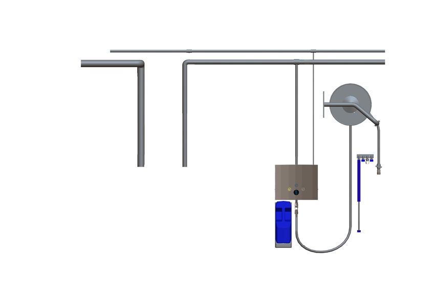
Declaration of Conformity                                               Konformitätserklärung
We Nilfisk FOOD, declare under our sole responsibility that the        Nilfisk FOOD, als alleinverantwortlich, erklären hiermit, dass:
products Hybrid ECO, to which this declaration relates, are in         Hybrid ECO.
conformity with these Council directives on the approximation of the   In Übereinstimmung mit den Richtlinien zur Angleichung der
laws of the EC menber states:                                          Rechtsvorschriften der Mitgliedstaaten ist:

Function: Hygiene Station                                              Funktion: Hygienestation
Model/Type: SE11.                                                      Modell/Typ: SE11.
Serial number: All                                                     Seriennummer: Alle

Machinery Directive (2006/42/EC:2006-05-17).                           Maschinendirektive (2006/42/EC:2006-05-17).
Standard used: EN 12100-1/A1:2009 and EN 12100-2/A1:2009.              Standarden: EN 12100-1/A1:2009 und EN 12100-2/A1:2009.

        Déclaration de conformité                                              Dichiarazione di conformità
Nous, Nilfisk FOOD, déclarons sous notre propre responsabilité que     Nilfisk FOOD dichiara sotto la sua esclusiva responsabilità
les produits Hybrid ECO, auxquels se réfère cette déclaration, sont    che i prodotti Hybrid ECO, ai quali fa riferimento la presente
conformes à ces directives du Conseil sur le rapprochement des         dichiarazione, sono conformi alle direttive del Consiglio concernenti il
législations des États membres :                                       riavvicinamento delle legislazioni degli stati membri della UE:

Fonction : Station d’hygiène                                           Funzione: Stazione di igiene
Modèle/Type : SE11.                                                    Modello/Tipo: SE11.
Numéro de série : Tous                                                 Numero di serie: Tutti

Directive 2006/42/CE du 17 mai 2006 relative aux machines              Direttiva Macchine (2006/42/CE:2006-05-17).
Normes appliquées: EN 12100-1/A1:2009 et EN 12100-2/A1:2009.           Standard utilizzato: EN 12100-1/A1:2009 ed EN 12100-2/A1:2009.

        Declaración de conformidad                                             Declaração de Conformidade
Nosotros, Nilfisk FOOD, declaramos bajo nuestra única                  A Nilfisk FOOD declara, por sua exclusiva responsabilidade que os
responsabilidad que los productos Hybrid ECO, a los que se refiere     produtos Hybrid ECO, referidos nesta declaração, se encontram
esta declaración cumplen con las directivas de este Consejo sobre la   em conformidade com estas diretivas do Conselho relativas à
legislación de los estados miembros de la CE:                          aproximação das disposições legislativas dos Estados-Membros da
                                                                       CE:
Función: Estación de limpieza
Modelo/tipo: SE11.                                                     Função: Estação de higiene
Número de serie: All                                                   Modelo/Tipo: SE11.
                                                                       Número de série: Todos
Directiva sobre máquinas (2006/42/EC:2006-05-17).
Normativa usada: EN 12100-1/A1:2009 y EN 12100-2/A1:2009.              Diretiva relativa às máquinas (2006/42/CE:2006-05-17).
                                                                       Norma utilizada: EN 12100-1/A1:2009 e EN 12100-2/A1:2009.

       Δήλωση συμμόρφωσης                                                      Verklaring van overeenstemming
Εμείς η Nilfisk FOOD, δηλώνουμε υπό την αποκλειστική μας ευθύνη        Wij, Nilfisk FOOD, verklaren geheel onder eigen verantwoordelijkheid
ότι τα προϊόντα Hybrid ECO, Με τον οποίο σχετίζεται αυτή η δήλωση,     dat de producten Hybrid ECO, waarop deze verklaring betrekking
συμμορφώνονται με τις παρακάτω οδηγίες του συμβουλίου σχετικά με       heeft, in overeenstemming zijn met de volgende Richtlijnen van de
την προσέγγιση των νόμων των κρατών μελών της ΕΚ:                      Raad betreffende de onderlinge aanpassing van de wetgevingen van
                                                                       de EG-lidstaten:
Λειτουργία: Σταθμός υγιεινής
Μοντέλο/Τύπος: SE11.                                                   Functie: Hygiëne-installatie
Αριθμός σειράς: Όλοι                                                   Model/Type: SE11.
                                                                       Serienummer: Alle
Οδηγία περί μηχανημάτων (2006/42/EC:2006-05-17).
Χρησιμοποιούμενο πρότυπο: EN 12100-1/A1:2009 και EN 12100-2/           Machinerichtlijn (2006/42/EG:17-05-2006).
A1:2009.                                                               Toegepaste norm: EN 12100-1/A1:2009 en EN 12100-2/A1:2009.
Försäkran om överensstämmelse                                           Vaatimustenmukaisuusvakuutus
Vi Nilfisk FOOD, tillkännager, under eget ansvar, att                   Me Nilfisk FOOD vakuutamme yksinomaisella vastuulla, että tuotteet
produkterna Hybrid ECO, som omfattas av denna försäkran,                Hybrid ECO, jota tämä vakuutus koskee, noudattavat direktiivejä,
är i överensstämmelse med rådets direktiv om tillnärmning av            jotka käsittelevät EY:n jäsenvaltioiden lakien yhdenmukaisuutta
medlemsstaternas lagstiftning i EG:                                     koskien seuraavia:

Funktion: Hygienstation                                                 Toiminto: Hygienia-asema
Modell/typ: SE11.                                                       Malli/tyyppi: SE11.
Serienummer: Alla                                                       Sarjanumero: Kaikki

Maskindirektiv (2006/42/EC:2006-05-17).                                 Konedirektiivi (2006/42/EY:2006-05-17).
Standard som används: EN 12100-1/A1:2009 och EN 12100-2/                Käytetty standardi: EN 12100-1/A1:2009 ja EN 12100-2/A1:2009.
A1:2009.

       Overensstemmelseserklæring                                              Deklaracja zgodności
Nilfisk FOOD, erklærer under eneansvar, at produktet: Hybrid ECO,       Firma Nilfisk FOOD z pełną odpowiedzialnością oświadcza, że
som denne erklæring vedrører, er i overensstemmelse med følgende        produkty Hybrid ECO, których dotyczy ta deklaracja, spełniają
direktiver om tilnærmelse af EU medlemslandenes love:                   wymogi poniższych dyrektywa Rady zgodnymi z prawem
                                                                        obowiązującym państwa członkowskie UE:
Funktion: Hygiejnestation
Model/Type: SE11.                                                       Funkcja: Stacja higieniczna
Serienummer: Alle                                                       Model/typ: SE11.
                                                                        Numer seryjny: Wszystkie
Maskindirektiv (2006/42/EC:2006-05-17).
Standarder: EN 12100-1/A1:2009 og EN 12100-2/A1:2009.                   Dyrektywa Maszynowa (2006/42/EC:2006-05-17).
                                                                        Stosowana norma: EN 12100-1/A1:2009 i EN 12100-2/A1:2009.

        Декларация соответствия                                                Megfelelőségi nyilatkozat
Мы, Nilfisk FOOD, принимая на себя всю ответственность,                 Mi, a Nilfisk FOOD, kizárólagos felelősségünk tudatában kijelentjük,
заявляем, , что продукты Hybrid ECO, которых касается                   hogy a Hybrid ECO, Amelyekre ez a nyilatkozat vonatkozik,
настоящая декларация, соответствуют данным директивам                   megfelelnek az EU tagállamok törvényi rendelkezéseinek
Совета о приблизительном соответствии законам стран-членов              közelítéséről szóló tanácsi irányelveknek:
СЕ:
                                                                        Funkció: Higiéniai állomás
Функциональное назначение: Гигиеническая станция                        Modell/Típus: SE11.
Модель/Тип: SE11.                                                       Sorozatszám: Összes
Серийный номер: все
                                                                        Gépekre vonatkozó irányelv (2006/42/EC:2006-05-17).
Директива машин (2006/42/EC:17-05-2006).                                Alkalmazott szabvány: EN 12100-1/A1:2009 és EN 12100-2/
Используемый стандарт: EN 12100-1/A1:2009 и EN 12100-2/                 A1:2009.
A1:2009.

        Izjava o skladnosti                                                    Izjava o usklađenosti
V podjetju Nilfisk FOOD pod izključno odgovornostjo izjavljamo, da      Mi, tvrtka Nilfisk FOOD, izjavljuje pod potpunom odgovornošću da
so izdelki Hybrid ECO, na katere se nanaša ta deklaracija, skladni z    su proizvodi Hybrid ECO, na koje se ova izjava odnosi, sukladni
naslednjimi direktivami Sveta in ustreznimi zakoni v državah članicah   sa sljedećim uredbama Vijeća za približnost zakona država članica
ES:                                                                     Europske zajednice:

Funkcija: Higienska postaja                                             Funkcija: Higijenska postaja
Model/tip: SE11.                                                        Model/vrsta: SE11.
Serijska številka: Vse                                                  Serijski broj: Svi

Direktiva o strojih (2006/42/ES:2006-05-17).                            Izjava o strojevima (2006/42/EC:2006-05-17).
Uporabljeni standardi: EN 12100-1/A1:2009 in EN 12100-2/A1:2009.        Primijenjena norma: EN 12100-1/A1:2009 i EN 12100-2/A1:2009.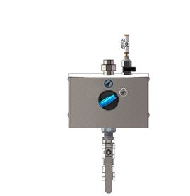
Deklaracija o konformitetu                                             Declaraţie de conformitate
Mi, Nilfisk FOOD, izjavljujemo pod sopstvenom isključivom              Subscrisa, Nilfisk FOOD, declară pe propria răspundere că
odgovornošću da su proizvodi Hybrid ECO, na koje se odnosi ova         produsele Hybrid ECO La care se referă prezenta declaraţie, sunt
izjava, u skladu sa direktivama Veća o primeni zakona država članica   în conformitate cu următoarele directive ale Consiliului privind
EZ:                                                                    apropierea legislaţiilor statelor membre CE:

Funkcija: Stanica za higijenu                                          Funcţie: Staţie de igienizare
Model/tip: SE11.                                                       Model/Tip: SE11.
serijski broj: Kompletna                                               Număr de serie: toate

Direktiva o mašinama (2006/42/EC:2006-05-17).                          Directiva Maşini (2006/42/EC:2006-05-17).
Primenjen standard: EN 12100-1/A1:2009 i EN 12100-2/A1:2009            Standarde utilizate: EN 12100-1/A1:2009 şi EN 12100-2/A1:2009.

.

       Декларация за съответствие                                              Prohlášení o shodě
Ние, Nilfisk FOOD, декларираме на своя отговорност, че                 Společnost Nilfisk FOOD na vlastní odpovědnost prohlašuje, že
продуктите Hybrid ECO, за които се отнася настоящата                   produkty Hybrid ECO, na které se toto prohlášení vztahuje, vyhovují
декларация, са в съответствие със следните директиви на                požadavkům následujících směrnic rady v rámci harmonizace se
Съвета относно сближаването на законодателствата на                    zákony členských států EU:
държавите членки на ЕО:
                                                                       Funkce: Hygienická stanice
Функция: Хигиенна станция                                              Model/Typ: SE11.
Модел/Тип: SE11.                                                       Výrobní číslo: Všechna
Сериен номер: Всички
                                                                       Směrnice o strojních zařízeních (2006/42/EC:2006-05-17).
Директива относно машините (2006/42/ЕО: 17.05.2006 г.).                Použitá norma: EN 12100-1/A1:2009 a EN 12100-2/A1:2009.
Използван стандарт: EN 12100-1/A1:2009 и EN 12100-2/A1:2009.

       Prehlásenie o zhode                                                    Uygunluk Beyanı
My, spoločnosť Nilfisk FOOD týmto na našu výhradnú zodpovednosť        Biz Nilfisk FOOD olarak tamamen kendi sorumluluğumuz altında
vyhlasujeme, že produkty Hybrid ECO, na ktoré sa toto vyhlásenie       beyan ederiz ki, bu beyanın konusu olan Hybrid ECO, ürünü AT üye
vzťahuje, sú v súlade s nasledujúcimi smernicami Rady o aproximácii    ülkelerinin yürürlükteki yasaları kapsamında Konsey direktiflerine
zákonov členských štátov ES:                                           uygundur:

Funkcia: Hygienická stanica                                            Fonksiyon: Hijyen İstasyonu
Model/typ: SE11.                                                       Model/Tip: SE11.
Sériové číslo: Všetky                                                  Seri numarası: Tümü

Smernica o strojných zariadeniach (2006/42/ES: 17.5.2006).             Makine Direktifi (2006/42/EC:2006-05-17).
Použitá norma: EN 12100-1/A1:2009 a EN 12100-2/A1:2009.                Kullanılmış standartlar: EN 12100-1/A1:2009 ve EN 12100-2/
                                                                       A1:2009.

        Vastavusdeklaratsioon                                                  Atitikties deklaracija
Käesolevaga kinnitab Nilfisk FOOD oma ainuvastutusel, et tooted        Mes, bendrovė „Nilfisk FOOD“, išimtinai savo atsakomybe
“ Hybrid ECO” mille kohta käesolev deklaratsioon kehtib, vastavad      pareiškiame, kad gaminiai pavadinimu „Hybrid ECO“, kuriems
nõukogu direktiividele ELi liikmesriikide õigusaktide ühtlustamise     taikoma ši deklaracija, atitinka šias Tarybos direktyvas dėl EB
kohta:                                                                 valstybių narių įstatymų suderinimo:

Funktsioon: Hügieenijaam                                               Paskirtis: Higienos terminalas
Mudel/tüüp: SE11.                                                      Modelis / tipas: SE11.
Seerianumber: kõik                                                     Serijos numeris: visi

Masinadirektiiv (2006/42/EÜ:2006-05-17).                               Mašinų direktyvą (2006/42/EB:2006-05-17),
Kasutatav standard: EN 12100-1/A1:2009 ja EN 12100-2/A1:2009.          taikytas standartas: EN 12100-1/A1:2009 ir EN 12100-2/A1:2009.
Atbilstības deklarācija Свідчення про відповідність вимогам
Mēs, uzņēmums „Nilfisk FOOD”, uzņemoties pilnu atbildību, Ми, Nilfisk FOOD, з повною відповідальністю заявляємо, що
apliecinām, ka produktu Hybrid ECO, uz kuru šī deklarācija attiecas, продукти Hybrid ECO, До яких відноситься ця декларація,
atbilst tālāk norādītajām Padomes direktīvām par ES dalībvalstu перебувають у відповідності до наведених нижче директив Ради
likumdošanas tuvināšanu. ЄС щодо зближення законодавства держав-членів ЄС:
Funkcija: Higiēnas stacija. Функція: Гігієнічна станція
Modelis/tips: SE11. Модель/Тип: SE11.
Sērijas numurs: visi. Серійний номер: усі
Mašīnu direktīva (2006/42/EK, 17.05.2006.) Директива щодо машинного обладнання (2006/42/EC:2006-05-17).
Izmantotais standarts: EN 12100-1/A1:2009 un EN 12100-2/A1:2009. Використаний стандарт: EN 12100-1/A1:2009 та EN 12100-2/
A1:2009.
Technical file responsible:
Flemming Asp
Nilfisk FOOD
Blytaekkervej 2 Signature:
9000 Aalborg, Denmark
Flemming Asp
R & D Manager
Aalborg d. 01-03-2021English (EN)
1.
1. Contents
Contents.. . . . . . . . . . . . . . . . . . . . . . . . . . . . . . . . . . . . . . . . . . . . . . . . . . . . . . . . . . . . . . . . . . . . . . . . . . . . . . . . . . . . . . . . . . . . . . . . . . . 7
2. Symbols used in this document ������������������������������������������������������������������������� 8
3. General information. . . . . . . . . . . . . . . . . . . . . . . . . . . . . . . . . . . . . . . . . . . . . . . . . . . . . . . . . . . . . . . . . . . . . . . . . . . . . . . . . . . . . . . 9
3.1. Identification Plate. . . . . . . . . . . . . . . . . . . . . . . . . . . . . . . . . . . . . . . . . . . . . . . . . . . . . . . . . . . . . . . . . . . . . . . . . . . . . . . . . . 10
3.2. Supplier.. . . . . . . . . . . . . . . . . . . . . . . . . . . . . . . . . . . . . . . . . . . . . . . . . . . . . . . . . . . . . . . . . . . . . . . . . . . . . . . . . . . . . . . . . . . 10
3.3. Specifications.. . . . . . . . . . . . . . . . . . . . . . . . . . . . . . . . . . . . . . . . . . . . . . . . . . . . . . . . . . . . . . . . . . . . . . . . . . . . . . . . . . . . . . 11
4. Overview and Use. . . . . . . . . . . . . . . . . . . . . . . . . . . . . . . . . . . . . . . . . . . . . . . . . . . . . . . . . . . . . . . . . . . . . . . . . . . . . . . . . . . . . . . . 12
5. System Safety.. . . . . . . . . . . . . . . . . . . . . . . . . . . . . . . . . . . . . . . . . . . . . . . . . . . . . . . . . . . . . . . . . . . . . . . . . . . . . . . . . . . . . . . . . . . . 12
5.1. Closing valve for water supply. ���������������������������������������������������������������������� 12
5.2. Closing valve for air supply. ������������������������������������������������������������������������� 12
5.3. Anticipated failures.. . . . . . . . . . . . . . . . . . . . . . . . . . . . . . . . . . . . . . . . . . . . . . . . . . . . . . . . . . . . . . . . . . . . . . . . . . . . . . . . . 12
5.4. Rest Risk.. . . . . . . . . . . . . . . . . . . . . . . . . . . . . . . . . . . . . . . . . . . . . . . . . . . . . . . . . . . . . . . . . . . . . . . . . . . . . . . . . . . . . . . . . . 13
6. Installation. . . . . . . . . . . . . . . . . . . . . . . . . . . . . . . . . . . . . . . . . . . . . . . . . . . . . . . . . . . . . . . . . . . . . . . . . . . . . . . . . . . . . . . . . . . . . . . . 13
6.1. Noise. . . . . . . . . . . . . . . . . . . . . . . . . . . . . . . . . . . . . . . . . . . . . . . . . . . . . . . . . . . . . . . . . . . . . . . . . . . . . . . . . . . . . . . . . . . . . . 13
6.2. Directions for Mounting ����������������������������������������������������������������������������� 13
6.3. Transportation.. . . . . . . . . . . . . . . . . . . . . . . . . . . . . . . . . . . . . . . . . . . . . . . . . . . . . . . . . . . . . . . . . . . . . . . . . . . . . . . . . . . . . 13
6.4. Vibrations. . . . . . . . . . . . . . . . . . . . . . . . . . . . . . . . . . . . . . . . . . . . . . . . . . . . . . . . . . . . . . . . . . . . . . . . . . . . . . . . . . . . . . . . . . 13
6.5. Water Connection.. . . . . . . . . . . . . . . . . . . . . . . . . . . . . . . . . . . . . . . . . . . . . . . . . . . . . . . . . . . . . . . . . . . . . . . . . . . . . . . . . . 13
6.6. Air Connection.. . . . . . . . . . . . . . . . . . . . . . . . . . . . . . . . . . . . . . . . . . . . . . . . . . . . . . . . . . . . . . . . . . . . . . . . . . . . . . . . . . . . . 14
6.6.1. Supply of Detergent �������������������������������������������������������������������������� 14
6.7. Hose Connection. . . . . . . . . . . . . . . . . . . . . . . . . . . . . . . . . . . . . . . . . . . . . . . . . . . . . . . . . . . . . . . . . . . . . . . . . . . . . . . . . . . 14
7. Operation procedures.. . . . . . . . . . . . . . . . . . . . . . . . . . . . . . . . . . . . . . . . . . . . . . . . . . . . . . . . . . . . . . . . . . . . . . . . . . . . . . . . . . . 15
7.1. Start up.. . . . . . . . . . . . . . . . . . . . . . . . . . . . . . . . . . . . . . . . . . . . . . . . . . . . . . . . . . . . . . . . . . . . . . . . . . . . . . . . . . . . . . . . . . . 15
7.1.1. Start 15
7.1.2. Stop 15
7.1.3. Adjustment of detergent ���������������������������������������������������������������������� 15
7.1.4. Adjustment of air ����������������������������������������������������������������������������� 15
7.2. Maintenance, trouble shooting and Service ���������������������������������������������������������� 16
8. Operation.. . . . . . . . . . . . . . . . . . . . . . . . . . . . . . . . . . . . . . . . . . . . . . . . . . . . . . . . . . . . . . . . . . . . . . . . . . . . . . . . . . . . . . . . . . . . . . . . . 16
8.1. Before Operation . . . . . . . . . . . . . . . . . . . . . . . . . . . . . . . . . . . . . . . . . . . . . . . . . . . . . . . . . . . . . . . . . . . . . . . . . . . . . . . . . . 16
8.2. Start/Stop (change, rinse, foam, des) ���������������������������������������������������������������� 16
9. Maintenance, Trouble shooting, Service ��������������������������������������������������������������� 17
9.1. Preventive maintenance ���������������������������������������������������������������������������� 17
9.2. Rinsing the chemical supply/injector system ��������������������������������������������������������� 17
9.3. Deliming. . . . . . . . . . . . . . . . . . . . . . . . . . . . . . . . . . . . . . . . . . . . . . . . . . . . . . . . . . . . . . . . . . . . . . . . . . . . . . . . . . . . . . . . . . . 17
9.4. Coupling. . . . . . . . . . . . . . . . . . . . . . . . . . . . . . . . . . . . . . . . . . . . . . . . . . . . . . . . . . . . . . . . . . . . . . . . . . . . . . . . . . . . . . . . . . . 17
9.5. Internal cleaning of the unit ������������������������������������������������������������������������� 17
9.6. Trouble Shooting and Remedy ���������������������������������������������������������������������� 18
10. Tools.. . . . . . . . . . . . . . . . . . . . . . . . . . . . . . . . . . . . . . . . . . . . . . . . . . . . . . . . . . . . . . . . . . . . . . . . . . . . . . . . . . . . . . . . . . . . . . . . . . . . . . 19
11. End of Use. . . . . . . . . . . . . . . . . . . . . . . . . . . . . . . . . . . . . . . . . . . . . . . . . . . . . . . . . . . . . . . . . . . . . . . . . . . . . . . . . . . . . . . . . . . . . . . . 20
11.1. Dismounting .. . . . . . . . . . . . . . . . . . . . . . . . . . . . . . . . . . . . . . . . . . . . . . . . . . . . . . . . . . . . . . . . . . . . . . . . . . . . . . . . . . . . . . 20
11.2. Disposal.. . . . . . . . . . . . . . . . . . . . . . . . . . . . . . . . . . . . . . . . . . . . . . . . . . . . . . . . . . . . . . . . . . . . . . . . . . . . . . . . . . . . . . . . . . . 20
Spare Part List and drawings.. . . . . . . . . . . . . . . . . . . . . . . . . . . . . . . . . . . . . . . . . . . . . . . . . . . . . . . . . . . . . . . . . . . . . . . . . . . . . . . . . 63
7English (EN)
2. Symbols used in this document
Read before Use
Wear glasses when using the unit.
Wear gloves and suitable clothing when using the unit.
Note:
A potentially damaging situation.
Possible consequences: The product or something in its
vicinity could be damaged. Prevention.
Caution:
A dangerous situation.'Possible consequences: light or minor
injuries. Can also be used in warn against damage to prop-
erty or other goods prevention.
Warning:
A Potentially dangerous situation.
Possible consequences: Death or severe injury Prevention.
Danger:
A dangerous situation.'Possible consequences: Death or
severe injury Prevention.
Danger:
Warning! Sharp edges – watch your fingers.
8English (EN)
3. General information
Nilfisk FOOD congratulates you
on your new low-pressure foam
and sanitising cleaning equipment.
The equipment provides the lat-
est standard of technology in low
pressure cleaning equipment in
your factory.
The equipment can be used for
rinsing, foaming and application of
disinfectants.
It is important that your operational
staff read these directions for use
prior to installation, start up and
use of the equipment.
9English (EN)
3.1. Identification Plate
1 3 2
Nilfisk Food, Blytækkervej 2, DK - 9000 Aalborg
5 Hybrid SE11
Art. no. 110006895
4 Date 20.08.2020 S/N 1450100xxx
Pressure Max 4 MPa Weight 3 kg
6 Water Max 30,00 L/min
Max Temp 70,00 °C
V Hz Amp
9
10
7 8 11 12 110006977
1. Producer
2. Serie No.
3. Type
4. Date of production
5. Article No.
6. Maximum pressure
7. Supply voltage
8. Frequecy
9. Maximum water consumption
10. Maximum temperature
11. Current
12. Weight.
3.2. Supplier
Nilfisk FOOD
Blytækkervej 2
DK-9000 Aalborg, Denmark
Tel.: +45 7218 2000
CVR no. 6257 2213
www.nilfiskfood.com
10English (EN)
3.3. Specifications
Technical Data
Water
Connection type inlet ISO 228/1-G1/2
Connection type outlet 1/2” quick coupler
Recommended inlet pipe dimension (min) 3/4’’ (1/2”)
Water consumption - foaming 7.8 l/min@20 bar
Water consumption - spraying 7.8 l/min@20 bar
Water consumption - rinsing 26 l/min@20 bar
Min. inlet pressure 8 bar
Max. inlet pressure 25 bar
Max. water temperature 70°C
Compressed air supply
Connection type inlet Ø6 mm push in
Min. pressure of air supply 6 bar
Max. pressure of air supply 9 bar
Required flow rate 75 Nl/min
Nozzles (recommended)
Rinsing nozzle 25/30
Foam nozzle 50/150
Spray nozzle 40/30
General
Number of products 1
Max. hose length (recommended) 30m (25m)
Weight 3,2 kg
Dimensions H x W x D 388x203x128
11English (EN)
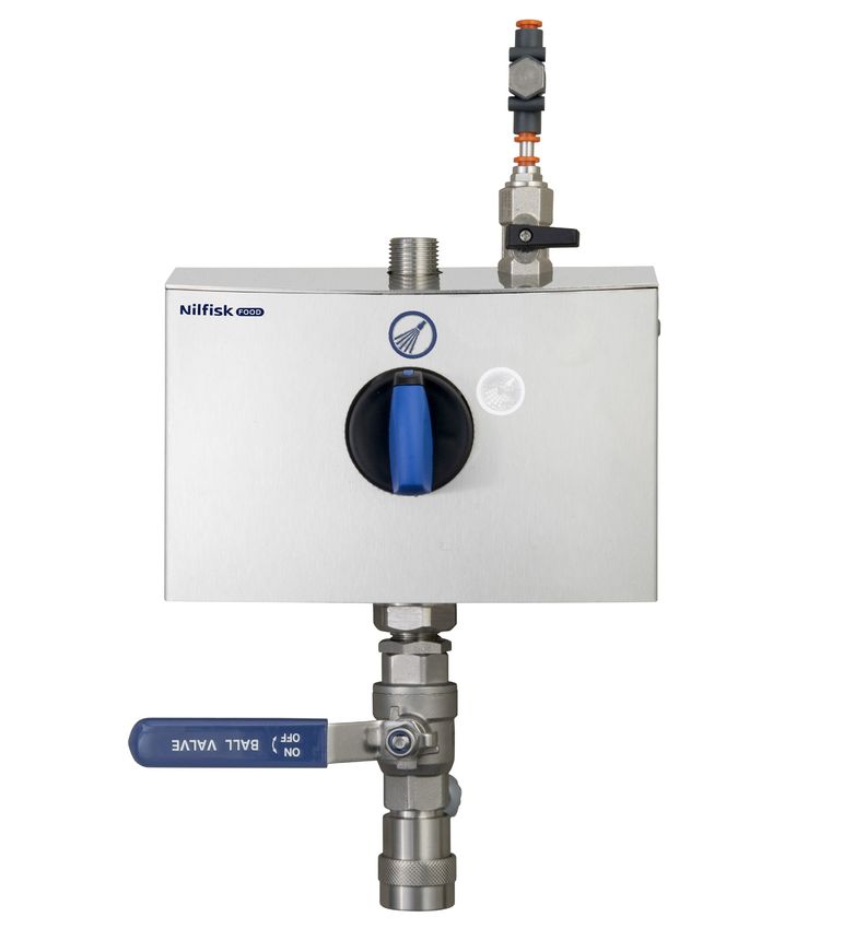
5.2. Closing valve for air supply.
4. Overview and Use We recommend mounting a closing valve with two air
The ECO unit is a complete cleaning station to be non-return valves on the air inlet.
connected to a booster unit or a main station. The This makes it possible to disconnect the air supply
unit requires sufficient supply of water, compressed and prevent backflow of air.
air and detergent or desinfectant. .
Consumptions:
The unit is approved for the use of detergents or
Wear glasses when using the unit.
disinfectants.
Warning: Do not change the settings
made or recommended by the supplier
of the detergents!
Wear gloves and suitable clothing
when using the unit.
Detergents are supplied via a User Pack system or
from separate standard cans. Supply is also possible
via piping systems.
Before installation and set up of the unit always
read this instruction thoroughly. Always make sure 5.3. Anticipated failures
to follow personal safty procedures for chemicals in Bursted air tube in unit:
connection with refilling procedures (product change), • The unit must never be used without the front
maintenance and repair. See also product label and cover being mounted.
MSDS sheet. • The air closing valve on /in connection with the
unit must always be closed when not in use.
Safety instructions • Air tube and fitting should be examined regularly
Only professional service personel are allowed to and exchanged in case of visible damages.
carry out service and repairs on the unit.
Breakdown of non-return valves for air and water:
Only instructed personel are allowed to operate the • The unit must never be used without the cover
unit. beeing mounted.
• Air and water closing valve on/in connection with
the unit must always be closed when the unit is
5. System Safety
not in use.
In case of error/defect or service on equipment: • After use of the unit all chemical non-return valves
1. close the water supply must be thorougly rinsed with clean water. Follow
2. close the air supply instructions in paragraph 9.2.
• Non-return valves for air and water should be
5.1. Closing valve for water supply. examined minimum once a year by authorised
With this valve the unit can be isolated from the water personel for defects.
supply. Further, a non-return valve is built in the block Repair of unit:
to prevent backflow of water. • Do not attempt to repair a defect unit by yourself.
Always contact an authorised service company.
• Block and mark any defect unit in order to avoid
unintended use - se paragraf below regarding
"Rest risk - Use of the unit”
• For safety reasons only use approved and original
spare parts.
Fig 1 110006978
12English (EN)
5.4. Rest Risk 6.3. Transportation
Use of Unit: For secure transportation of the unit, we recommend
• Never use the unit without prior instructions in use always to ensure, that the unit can not slide or tip.
of the unit and its safety instructions. The instruc- The unit might have to be secured with straps.
tion must be prepared by an educated/instructed Transportation of the unit only in horisontal position:
personel. The unit must not be placed on the front where you
• Never use the unit without having read the en- find the operation panel. Neither can it be placed
closed guide and safety instructions. on top or bottom where connections and outlets are
• Always close water and air supply after use. mounted.
Damaged unit: In case the unit is moved at a temperature of approx
• Never use the unit if leakages (air, water or chemi- or below 0°C (32°F), you must always make sure that
cal) are observed. the the unit has been fully emptied for water. If this is
• Never use the unit if it is not possible to operate not the case, you may damage the unit.
the closing valves and/or if it is not possible to
select required operation. 6.4. Vibrations
• Never use the unit if it has been dislodged for its Hand-arm vibrations according to ISO 5349-1
original place of mounting.
6.5. Water Connection
6. Installation • Before the unit is connected to the
water supply pipe, the supply line
For safety reasons it is important to read all of the should be rinsed carefully in order to
enclosed information before installation of this equip- remove coarse impurities and metal
ment. In addition, the legislation in force at the time of shavings.
purchase must always be considered in connection • The connection for water must be
with the installation and mounting of this equipment, made at the top of the unit. (see lay-
no matter the contents of this manual.If there are mat- out drawing).
ters of dispute please contact your dealer. • Minimum internal diameter of the sup-
ply pipe must be at least 1/2” external
6.1. Noise (ø16mm internal).
Sound level according to ISO 11202; Below 70 dB • The unit must be fitted with a closing
valve for water on the inlet (see layout
6.2. Directions for Mounting drawing).
• The unit should be mounted in frost- • The pressure loss in the supply line
free rooms only. must be held as low as possible by
• The unit can be mounted on a wall - avoiding long supply pipes
or on a separate frame which may - mounting low pressure resistance
be installed in production areas and ball valves and
anchored to the floor. - avoiding fittings with high pressure
• For mounting on walls, please note loss.
the following: • When installing the piping, take care
• The wall for mounting should be to avoid air traps.
either a stable brick wall or a wall • All pipe connections to the unit must
made of concrete.
be screwed connections ensuring
simple maintenance and dismantling
• The delivered bracket should be of the station.
secured to the wall by the enclosed
screws and corresponding dowels Max. allowed temperature of supply water: 70°C
• The wall bracket should be mounted Max. allowed pressure of supply water: 25 bar
on the wall according to the above Water consumption at rinsing mode: 26 l/min
description and the station is hung
on to the bracket. The hose and User
Pack holders should be mounted af- For an optimum functioning of the
terwards. (See Installation/Mounting) injector system, we recommend install-
ing a filter on the inlet to avoid impuri-
ties.
13English (EN)
6.6. Air Connection
Before the unit is connected to the air
supply, the pipe system must be care-
fully rinsed in order to remove coarse
impurities.
• The unit requires an air supply boosting
- an inlet pressure of minimum 6 bar
- a minimum capacity of 200 l/min.
110003498
A with clean water; place the foam nozzle and open
the spray gun/outlet valve. The product inlet line is
now rinsed with clean water before use of another
product or.
Water inlet 6.7. Hose Connection
• The special hose fitted with spray gun/outlet valve
110003290 is connected to the outlet quick coupling of the unit
(layout drawing).
6.6.1. Supply of Detergent • Maximum hose length: 30 m.
Satellite without User Pack System. • It is recommended only to use Nilfisk FOOD
See drawing no 110003498 hoses, which have been tested for resistance.
• Place the can with detergent in the can holder
• Check the suction filter for impurities.
• Put the suction hose into the can below product
level and avoid suction of air.
• After pre-rinsing, check again that the hose is
sufficiently below product level and avoid suction
of air during foam or spray operation.
• After use of and when changing product as well
as after use of the unit, remove the hose from the
can and rinse the product inlet line and injector
with clean water.
Satellite with User Pack System
See drawing no 110003485.
• Place the specially designed User Pack in the
automatic holder.
• If changing to a different product when ending the
cleaning process, rinse the product inlet line with
clean water as follows:
• Replace the User Pack containing product by one
H20 H20
>20 sec.
110003485
14English (EN)
7. Operation procedures
All tests have been made with Topax 12
7.1. Start up
7.1.1. Start
1. Make sure that the water and air supply to the Nozzle colour Concentration
unit is open. For air see layout drawing. In case at 20 bar/290 PSI
of central chemical supply this must be activated
too.
2. Select requested function. Use the unit according Clear 0,36%
to the ”User Guide”. Pink 0,51%
7.1.2. Stop Light blue 0,64%
1. Close the water supply (layout drawing).
Purple 0,70%
2. Close the air supply (layout drawing).
3. Deactivate chemical supply by pulling up the suc- Turquios 1,43%
tion hose or removing the userpack. Yellow 1,95%
Brown 2,01%
Due to the following it is very important
to close water, air and chemical suplly Orange 2,18%
when the unit not in use. Green 2,62%
• If the air supply is open when the unit Tan 3,94%
is not in use - air might seep into the Blue 4,88%
water pipe - which means that the White 6,02%
system has to be bled again.
Red 6,87%
Beige 7,36%
Black 7,86%
Grey 7,96%
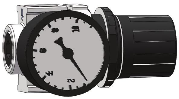
7.1.4. Adjustment of air
Remove the cover from the unit.
Adjust the air pressure on the reduction valve until an
appropriate foam quality is reached.
110007085 When setting the regulator, carefully
pull up the knob and turn it clockwise
for pressure increase and counter clock
7.1.3. Adjustment of detergent
wise for pressure decrease.
Remove cover from the unit.
Adjustment of detergent can be done either by means
of a limiting nozzle or by means of a dosing valve
(layout drawing).
Turn clockwise to decrease air pressure
The limiting nozzle is placed in the suction nipple of
the non-retur valve (110007085) and can be re-
placed with a smaller or larger nozzle depending on
the concentration needed, please also see table for Pull the
guidelines. knob to
adjust
air
pressure
Turn counter clockwise to increase air pressure
15English (EN)
7.2. Maintenance, trouble shooting and Service
Maintenance Instructions 8. Operation
1. Quick couplings; it is recommended to lubricate
8.1. Before Operation
all couplings parts regularly, approx. once a
If the wall the unit is to be mounted on is made of
month) by water proof grease to prevent leaks
bricks or concrete, the enclosed screws and rawl
and damage of o-rings.
plugs are usable, otherwise you have to make sure
2. If the quick couplings leak, o-rings should be
that the carrying capacity of the wall is sufficient.
replaced.
3. Depending on usage, maintenance should be The pipeline must be rinsed through
undertaken by an authorised service engineer at before the system is connected.
least once a year in order to prevent defects and
failure of operation. Authorised engineers are
persons who due to their skills and experience Remove cover before the unit is mount-
have sufficient knowledge of Hygiene Systems ed on the wall.
and are confident with the state work safety regu-
lations, accident preventing regulations, lines and
generally acknowledged technical regulations
8.2. Start/Stop (change, rinse, foam, des)
such as DIN-norms and VDE-provisions. For
your safety, this cleaning unit has been manufac- Start satellite
tured according to all relevant regulations valid 1. Check that water- and air supplies for the system
in the EU and therefore it has been supplied with are open.
the CE-marking. For further information, please 2. Make sure that the water and air supply to the
refer to the service department. unit is open. For air see layout drawing. In case
4. When the cleaning process has been completed of central chemical supply this must be activated
or chemicals have been changed, it is important too.
to rinse the suction and injector systems in the 3. Select requested function. Use the unit according
following way: to the ”User Guide”.
5. Replace the can with a can containing clean
water. Stop satellite
6. Put the suction hose into the water can. 1. Turn off the water supply
• Connect the foam nozzle. 2. Close the air supply
• Open the spray gun/outlet valve and keep it open It is important to shut off the water and
until the injector has been rinsed through (approx. air when the unit is left after use .
30 seconds).
• Remove the suction hose from the water can.
• If the air supply is open when the unit are not in
7. It is recommended to descale the unit according
use, air may seep into the water pipe. If this is the
to pharagraph 9.3
case the system may have to be bled again.
8. It is recommended to clean the surface inside the
It may be necessary to bleed the pipes and the unit
unit at least once a month in order to maintain
again after it has been closed for a longer period of
parts and avoid corrosion of parts.
time (holidays, and the like)
CAUTION
The chemical supply must always be
rinsed thoroughly after use
1. The following procedure will clean the chemical
supply for detergents and/or remains of disinfect-
ants.
2. Remove User Pack or standard can.
3. Hold the rinsing bottle with clean water tightly
against the suction opening (with User Pack).
Alternatively, you can place a User Pack with
clean water in the holder or – without User Pack
– place the hose in a bucket of clean water.
4. 3. Activate the hose handle until clean water
comes out of the nozzle (approx. 30 seconds)
16English (EN)
• Mount the air valve and the non-return valve on
9. Maintenance, Trouble shooting, the injector block and mount the injector block in
Service the unit.
• Connect water to the unit.
9.1. Preventive maintenance • Test the unit in Foam position make sure the vacu-
Depending on usage, maintenance should be un- um is sufficient, it is recommended to be between
dertaken by an authorised service engineer at least 14,8 - 20,7 inHg / -0.05 - 0.07 MPa.
once a year in order to prevent defects and failure of • Test that the unit can start and stop in both foam
operation. Authorised engineers are persons who due and rinse position
to their skills and experience have sufficient knowl- • Reinstall the cover on the unit
edge of the Hygiene Systems and are confident with The following deliming interwals must be observed to
the state work safety regulations, accident preventing prevent lime building up in the unit, that can discon-
regulations, lines and generally acknowledged techni- tinue operation of the unit
cal regulations such as DIN-norms and VDE-provi-
°dH ppm Time between Deliming
sions. For your safety, this cleaning unit has been
manufactured according to all relevant regulations 0-5 18-90 12 months
valid in the EU and therefore it has been supplied with 5-10 90-180 6 to 12 months
the CE-marking. For further information, please refer 10-15 180-270 3 to 6 months
to the service department. 15-20 270-360 3 to 6 months
9.2. Rinsing the chemical supply/injector system >20 >360 1 to 3 months
The chemist supply must always be 9.4. Coupling
rinsed thoroughly after use. It is recommended to lubricate all coupling parts regu-
larly (approx. once a week) with waterproof grease
to prevent leaks and damage of packings. If the unit
Remains of detergents or disinfectants can clog the
is equipped with a spray gun the piston of the gun
injector so it needs to be rinsed or replaced.
should also be lubricated.
The following procedure will clean the chemistry sup-
In leaking quick couplings the packings should be
ply for detergents and/or remains of disinfectants.
replaced.
1. Remove User Pack, if any.
2. Hold the rinsing bottle with clean water tightly
against the suction opening (with User Pack) or 9.5. Internal cleaning of the unit
against the hose (without User Pack). Alternati- We recommend opening and cleaning the unit inside
vely, you can place a User Pack with clean water min. once a week.
in the holder or – without User Pack – place the
hose in a bucket of clean water.
3. Activate the hose handle until clean water comes
out of the nozzle (approx. 30 seconds).
This procedure should be
followed both on the detergent
and the disinfectant side (if this is
installed).
9.3. Deliming
• The interval of the Deliming procedure is depens
the water hardness.
• Make sure the water to the unit is disconnected.
• Remove the Cover from the unit.
• Dismount the injector block. Dismount the air valve
and the non-return valve for air, inclusive of the air
fittings.
• Put the injector block in a deliming bath – make
sure the dosing valve (the knob) is over the sur-
face.
• Wait for 60 minutes.
• Rinse the block in clean water.
17English (EN)
9.6. Trouble Shooting and Remedy
Fault Cause Remedy
No pressure / too low pressure Insufficient or No water supply. Open water supply valve
(See 5.1 - Closing valve).
Is the filter if any clogged. Clean the filter.
Rinsing nozzle not installed. Place rinsing nozzle.
Insufficint or No foam creating. No supply of dilute products. Consult directions for use of dos-
ing unit.
Product not suitable. Choose suitable product.
Insufficient or No air supply. Provide sufficient air supply.
Air pressure in mixing chamber too Adjust air pressure setting.
high.
Defect non-return valve for air. Replace non-return valve for air.
Incorrect nozzle. Place foam nozzle 50/150.
Non-return valve blocked Clean or replace non-return valve.
Injektor /mixing chamber blocked Clean nozzle
No spray sanitising. No supply of dilute products. Consult directions for use of dos-
ing unit.
Non-return valve blocked. Clean or replace non-return
valve.
Injektor /mixing chamber blocked Clean Injektor /mixing chamber.
In case of errors/troubles not mentioned above, please contact your local service technician for further assis-
tance.
18English (EN)
10. Tools
Standard tools that are useful/necessary for service and maintenance on the full range of equipment.
BF/BW & MB Booster Satellites
Mainstation BF/BW & MB Booster
Foamatic Mainstation Mainstation
Foamatic Satellites
Foamatic Mainstation
Satellites Satellites
BF/BW & MB Booster BF/BW & MB Booster
Mainstation Mainstation
Foamatic Satellites Foamatic Satellites
Foamatic Mainstation Foamatic Mainstation
BF/BW & MB Booster Foamatic Satellites
Foamatic Mainstation
Satellites Satellites
BF/BW & MB Booster Mainstation
Mainstation Foamatic Satellites
Foamatic Satellites Foamatic Mainstation
Foamatic Mainstation
19English (EN)
11. End of Use
11.1. Dismounting
Close all supply valves and remove the unit from wall.
11.2. Disposal
In case the unit should be disposed, it must be sepa-
rated and sorted in eg-recyclable and non recyclable
parts.
The steel construction is easily separated and dis-
posed and constitutes no environmental risk - nor for
the user.
Disposal must be made according to rules and regu-
lations in force for disposal of machines as well as all
standards in connection with environmental protec-
tion.
CAUTION
Disposal of electronic components
and other remedies must be handled
as special disposal when disposed.
Alternatively, it can be disposed by a
specialised disposal company.
201.1. Inhalt. . . . . . . . . . . . . . . . . . . . . . . . . . . . . . . . . . . . . . . . . . . . . . . . . . . . . . . . . . . . . . . . . . . . . . . . . . . . . . . . . . . . . . . . . . . . . . . . . . . . .
Inhalt 21
2. In diesem Dokument verwendete Symbole ������������������������������������������������������������� 22
3. Allgemeine Informationen ������������������������������������������������������������������������������� 23
3.1. Kennzeichnungsschild ������������������������������������������������������������������������������ 24
3.2. Anbieter.. . . . . . . . . . . . . . . . . . . . . . . . . . . . . . . . . . . . . . . . . . . . . . . . . . . . . . . . . . . . . . . . . . . . . . . . . . . . . . . . . . . . . . . . . . . 24
3.3. Spezifikationen.. . . . . . . . . . . . . . . . . . . . . . . . . . . . . . . . . . . . . . . . . . . . . . . . . . . . . . . . . . . . . . . . . . . . . . . . . . . . . . . . . . . . 25
4. Überblick und Gebrauch. . . . . . . . . . . . . . . . . . . . . . . . . . . . . . . . . . . . . . . . . . . . . . . . . . . . . . . . . . . . . . . . . . . . . . . . . . . . . . . . . 26
5. Systemsicherheit. . . . . . . . . . . . . . . . . . . . . . . . . . . . . . . . . . . . . . . . . . . . . . . . . . . . . . . . . . . . . . . . . . . . . . . . . . . . . . . . . . . . . . . . . 26
5.1. Verschlussventil für Wasserzufuhr. (Zubehör) �������������������������������������������������������� 26
5.2. Verschlussventil für Luftzufuhr. ���������������������������������������������������������������������� 26
5.3. Voraussichtliche Ausfälle ��������������������������������������������������������������������������� 26
Deutsch (DE)
5.4. Restrisiko. . . . . . . . . . . . . . . . . . . . . . . . . . . . . . . . . . . . . . . . . . . . . . . . . . . . . . . . . . . . . . . . . . . . . . . . . . . . . . . . . . . . . . . . . . 27
6. Installation. . . . . . . . . . . . . . . . . . . . . . . . . . . . . . . . . . . . . . . . . . . . . . . . . . . . . . . . . . . . . . . . . . . . . . . . . . . . . . . . . . . . . . . . . . . . . . . . 27
6.1. Störgeräusche.. . . . . . . . . . . . . . . . . . . . . . . . . . . . . . . . . . . . . . . . . . . . . . . . . . . . . . . . . . . . . . . . . . . . . . . . . . . . . . . . . . . . . 27
6.2. Montageanleitung.. . . . . . . . . . . . . . . . . . . . . . . . . . . . . . . . . . . . . . . . . . . . . . . . . . . . . . . . . . . . . . . . . . . . . . . . . . . . . . . . . . 27
6.3. Transport.. . . . . . . . . . . . . . . . . . . . . . . . . . . . . . . . . . . . . . . . . . . . . . . . . . . . . . . . . . . . . . . . . . . . . . . . . . . . . . . . . . . . . . . . . . 27
6.4. Vibrationen.. . . . . . . . . . . . . . . . . . . . . . . . . . . . . . . . . . . . . . . . . . . . . . . . . . . . . . . . . . . . . . . . . . . . . . . . . . . . . . . . . . . . . . . . 27
6.5. Wasseranschluss.. . . . . . . . . . . . . . . . . . . . . . . . . . . . . . . . . . . . . . . . . . . . . . . . . . . . . . . . . . . . . . . . . . . . . . . . . . . . . . . . . . 27
6.6. Luftanschluss.. . . . . . . . . . . . . . . . . . . . . . . . . . . . . . . . . . . . . . . . . . . . . . . . . . . . . . . . . . . . . . . . . . . . . . . . . . . . . . . . . . . . . . 28
6.6.1. Versorgung mit Reinigungsmittel 28
6.7. Schlauchverbindung ������������������������������������������������������������������������������� 28
7. Betriebsverfahren.. . . . . . . . . . . . . . . . . . . . . . . . . . . . . . . . . . . . . . . . . . . . . . . . . . . . . . . . . . . . . . . . . . . . . . . . . . . . . . . . . . . . . . . . 29
7.1. Inbetriebnahme.. . . . . . . . . . . . . . . . . . . . . . . . . . . . . . . . . . . . . . . . . . . . . . . . . . . . . . . . . . . . . . . . . . . . . . . . . . . . . . . . . . . . 29
7.1.1. Start 29
7.1.2. Stopp 29
7.1.3. Einstellung des Reinigungsmittels 29
7.1.4. Einstellung der Luft ��������������������������������������������������������������������������� 29
7.2. Wartung, Problemanalyse und Kundendienst �������������������������������������������������������� 29
8. Betrieb.. . . . . . . . . . . . . . . . . . . . . . . . . . . . . . . . . . . . . . . . . . . . . . . . . . . . . . . . . . . . . . . . . . . . . . . . . . . . . . . . . . . . . . . . . . . . . . . . . . . . 30
8.1. Vor dem Betrieb .. . . . . . . . . . . . . . . . . . . . . . . . . . . . . . . . . . . . . . . . . . . . . . . . . . . . . . . . . . . . . . . . . . . . . . . . . . . . . . . . . . 30
8.2. Start/Stopp (wechseln, spülen, aufschäumen) �������������������������������������������������������� 30
9. Wartung, Problemanalyse und Kundendienst ���������������������������������������������������������� 30
9.1. Vorbeugende Wartung ����������������������������������������������������������������������������� 31
9.2. Spülung der Chemieversorgung/Injektorsystem ������������������������������������������������������ 31
9.3. Entkalken. . . . . . . . . . . . . . . . . . . . . . . . . . . . . . . . . . . . . . . . . . . . . . . . . . . . . . . . . . . . . . . . . . . . . . . . . . . . . . . . . . . . . . . . . . 31
9.4. Kupplung.. . . . . . . . . . . . . . . . . . . . . . . . . . . . . . . . . . . . . . . . . . . . . . . . . . . . . . . . . . . . . . . . . . . . . . . . . . . . . . . . . . . . . . . . . . 31
9.5. Innenreinigung des Geräts �������������������������������������������������������������������������� 31
9.6. Problemanalyse und Behebung Anzeichen ���������������������������������������������������������� 31
10. Werkzeuge. . . . . . . . . . . . . . . . . . . . . . . . . . . . . . . . . . . . . . . . . . . . . . . . . . . . . . . . . . . . . . . . . . . . . . . . . . . . . . . . . . . . . . . . . . . . . . . . 32
11. Nach der Verwendung.. . . . . . . . . . . . . . . . . . . . . . . . . . . . . . . . . . . . . . . . . . . . . . . . . . . . . . . . . . . . . . . . . . . . . . . . . . . . . . . . . . . 33
11.1. Demontage .. . . . . . . . . . . . . . . . . . . . . . . . . . . . . . . . . . . . . . . . . . . . . . . . . . . . . . . . . . . . . . . . . . . . . . . . . . . . . . . . . . . . . . 34
11.2. Entsorgung. . . . . . . . . . . . . . . . . . . . . . . . . . . . . . . . . . . . . . . . . . . . . . . . . . . . . . . . . . . . . . . . . . . . . . . . . . . . . . . . . . . . . . . 34
Spare Part List and drawings.. . . . . . . . . . . . . . . . . . . . . . . . . . . . . . . . . . . . . . . . . . . . . . . . . . . . . . . . . . . . . . . . . . . . . . . . . . . . . . . . . 63
212. In diesem Dokument verwendete Symbole
Bitte vor Inbetriebnahme lesen.
Bitte tragen Sie bei der Bedienung des Geräts eine Brille.
Deutsch (DE)
Bitte tragen Sie bei Benutzung des Geräts Handschuhe und
passende Kleidung.
Beachten Sie:
Eine potenziell gefährliche Situation.
Mögliche Konsequenzen: Das Produkt oder etwas in seiner
Nähe könnte beschädigt sein. Prävention.
Vorsicht:
Eine gefährliche Situation. 'Mögliche Konsequenzen: Leichte
oder geringfügige Verletzungen. Kann auch genutzt werden,
um vor Sachbeschädigung oder vor Beschädigung anderer
Güter zu warnen. Prävention.
Warnung:
Eine potenziell gefährliche Situation.
Mögliche Konsequenzen: Tod oder schwere Verletzungen.
Prävention.
Gefahr:
Eine gefährliche Situation. 'Mögliche Konsequenzen: Tod
oder schwere Verletzungen. Prävention.
Achtung:
Warnung! Scharfe Kanten - achten Sie auf Ihre Finger
223. Allgemeine
Informationen
Nilfisk FOOD beglückwünscht Sie
zu Ihrer Niederdruckschaum- und
Desinfektionsreinigungsanlage.
Die Anlage ist auf dem neuesten
Stand der Technik im Bereich der
Niederdruck-Reinigungsanlagen in
Deutsch (DE)
Ihrem Betrieb.
Die Anlage kann zum Spülen,
Schäumen und der Anwendung
von Desinfektionsmitteln einge-
setzt werden.
Es ist äußerst wichtig, dass Ihr
operatives Personal diese An-
weisungen vor der Installation,
Inbetriebnahme und der Nutzung
der Geräte durchliest.
233.1. Kennzeichnungsschild
1 3 2
Nilfisk Food, Blytækkervej 2, DK - 9000 Aalborg
5 Hybrid SE11
Art. no. 110006895
Deutsch (DE)
4 Date 20.08.2020 S/N 1450100xxx
Pressure Max 4 MPa Weight 3 kg
6 Water Max 30,00 L/min
Max Temp 70,00 °C
V Hz Amp
9
10
7 8 11 12 110006977
1. Hersteller.
2. Seriennr.
3. Modell.
4. Herstellungsdatum.
5. Artikelnr.
6. Maximaler Druck.
7. Versorgungsspannung.
8. Frequenz.
9. Maximaler Wasserverbrauch.
10. Höchsttemperatur
11. Stromstärke
12. Gewicht.
3.2. Anbieter
Nilfisk FOOD
Blytækkervej 2
DK-9000 Aalborg, Denmark
Tel.: +45 7218 2000
CVR no. 6257 2213
www.nilfiskfood.com
243.3. Spezifikationen
Technische Daten
Wasser
Anschlusstyp Einlass ISO 228/1-G1/2
Anschlusstyp Auslass 1/2” quick coupler
Empfohlener 3/4’’ (1/2”)
Einlassrohrdurchmesser (min)
Wasserverbrauch - Schaummodus 7.8 l/min@20 bar
Deutsch (DE)
Wasserverbrauch - Sprühmodus 7.8 l/min@20 bar
Wasserverbrauch - Spülmodus 26 l/min@20 bar
Min. Einglassdruck 8 bar
Max. Einlassdruck 25 bar
Max. Wassertemperatur 70°C
Druckluftversorgung
Anschluss typ Einlass Ø6 mm push in
Min. Luftdruckversorgung 6 bar
Max. Luftdruckversorgung 9 bar
Erforderliche Durchflussmenge 75 Nl/min
Düsen (empfohlener)
Spüldüse 25/30
Schaumdüse 50/150
Sprühdüse 40/30
Allgemeines
Anzahl der Produkte 1
Max. Schlauchlänge (empfohlen) 30m (25m)
Gewicht 3,2 kg
Abmessungen H x B x T 388x203x128
255.2. Verschlussventil für Luftzufuhr.
4. Überblick und Gebrauch Wir empfehlen die Montage eines Schließventils mit
zwei Luft-Rückschlagventilen am Lufteintritt. Das er-
Die ECO Anlage ist eine komplette Reinigungsstation,
möglicht eine Trennung der Luftzufuhr und verhindert
die mit einer Booster-Unit oder Hauptstation verbunden
einen Rückfluss von Luft.
werden kann. Die Anlage erfordert eine ausreichende
Versorgung von Wasser, Druckluft und Reinigungs- und Bitte tragen Sie bei der Bedienung
Infektionsmitteln. des Geräts eine Brille.
Verbrauch:
Die Anlage ist für den Einsatz von Reinigungs- und Des-
infektionsmitteln zugelassen.
Bitte tragen Sie bei Benutzung des
Geräts Handschuhe und passende
Deutsch (DE)
Warnung: Verändern Sie nicht die
vom Anbieter der Reinigungsmittel Kleidung.
vorgenommenen und empfohlenen Ein-
stellungen!
Die Reinigungsmittel werden über ein Benutzerpaket-
5.3. Voraussichtliche Ausfälle
System oder von separaten Standard-Behältern bedient.
Geplatzter Luftschlauch im Gerät:
Die Versorgung ist auch über Rohrsysteme möglich.
• Das Gerät darf ohne die vormontierte Frontabdeck-
ung nicht verwendet werden.
Lesen Sie diese Bedienungsanleitung bitte aufmerksam
• Das Luftabsperrventil an / in Zusammenhang mit
durch, bevor Sie mit der Installation und Inbetriebnahme
dem Gerät muss bei Nichtgebrauch geschlossen
des Geräts beginnen. Folgen Sie immer den persönli-
werden.
chen Sicherheitsrichtlinien für Chemikalien in Zusam-
• Der Luftschlauch und Armaturen sollten regelmäßig
menhang mit den Wiederauffüllvorgängen (Produk-
überprüft und bei sichtbarer Beschädigung ausge-
twechsel), Wartung und Reparatur. Siehe auch die
tauscht werden.
Produktkennzeichen und das Sicherheitsdatenblatt.
Ausfall von Rückschlagventilen für Luft und Wasser.
Sicherheitshinweise • Das Gerät darf ohne die vormontierte Frontabdeck-
Nur das professionelle Service-Personal darf Service- ung nicht verwendet werden.
und Reparaturarbeiten am Gerät vornehmen. • Das Luft- und Wasserabsperrventil an / in Zusam-
menhang mit dem Gerät muss bei Nichtgebrauch
Nur eingewiesenes Personal darf das Gerät bedienen. geschlossen werden.
• Nach dem Gebrauch des Geräts müssen alle
5. Systemsicherheit Chemie-Rückschlagventile mit sauberem Wasser
abgespült werden. Folgen Sie den Anweisungen in
Im Falle von Fehlern/Mängeln oder Service von Ger-
Abschnitt 9.2.
äten:
• Rückschlagventile für Luft und Wasser sollten mind-
1. Schließen Sie die Wasserzufuhr
estens einmal im Jahr von fachkundigem Personal
2. Schließen Sie die Luftzufuhr
auf Mängel überprüft werden.
5.1. Verschlussventil für Wasserzufuhr. (Zubehör)
Reparatur des Geräts:
Mit diesem Ventil kann das Gerät von der Wasserzufuhr
• Versuchen Sie nicht, das defekte Gerät selbst zu
getrennt werden. Des Weiteren wird ein Rückschlag-
reparieren. Kontaktieren Sie immer eine autorisierte
ventil in den Block eingebaut, um den Rückfluss des
Kundendienststelle.
Wassers zu verhindern.
• Blockieren und markieren Sie das defekte Gerät,
um eine unbeabsichtigte Benutzung zu vermeiden -
siehe Abschnitt unten über "Restrisiko - Benutzung
des Geräts"
• Benutzen Sie aus Sicherheitsgründen nur zugelass-
ene und originale Ersatzteile.
110006978
Fig 1
265.4. Restrisiko 6.3. Transport
Benutzung des Geräts: Für einen sicheren Transport der Anlage sollten Sie
• Benutzen Sie die Anlage nie ohne vorherige Einwei- sicherstellen, dass diese weder rutschen noch kippen
sung über den Gebrauch des Geräts und die Sicher- kann. Die Anlage sollte mit Gurten gesichert werden.
heitshinweise. Die Anweisungen müssen von einem Transport der Anlage nur in horizontaler Position: Die
geschulten/eingewiesenen Personal erstellt werden. Anlage sollte nicht auf der Vorderseite platziert werden,
• Benutzen Sie das Gerät nie, ohne die beigefügte an der sich das Bedienfeld befindet. Sie sollte auch
Gebrauchsanweisung und die Sicherheitshinweise nicht auf der Ober- oder Unterseite platziert werden, da
gelesen zu haben. dort Anschlüsse und Steckdosen montiert werden.
• Schließen Sie immer die Wasser- und Luftzufuhr Wenn die Anlage bei einer Temperatur von circa 0°C
nach Benutzung. (32°F) bewegt wird, sollten Sie immer sicherstellen,
dass die Anlage vollständig geleert ist. Wenn dies nicht
Beschädigtes Gerät: der Fall ist, können Sie die Anlage beschädigen.
• Benutzen Sie das Gerät nie, wenn undichte Stellen
Deutsch (DE)
beobachtet werden (Luft, Wasser oder Chemie). 6.4. Vibrationen
• Benutzen Sie das Gerät nie, wenn Sie die Ver-
Hand-Arm-Vibrationen entsprechend ISO 5349-1
schlussventile nicht bedienen können und/oder wenn
es nicht möglich ist, den gewünschten Vorgang
auszuwählen. 6.5. Wasseranschluss
• Benutzen Sie das Gerät nie, wenn es von seinem • Bevor die Anlage mit der Wasserzulau-
ursprünglichen Montageort entfernt wurde. fleitung verbunden ist, sollte die Ver-
sorgungsleitung vorsichtig abgespült
werden, um grobe Verunreinigungen
6. Installation und Metallspäne zu entfernen.
• Der Wasseranschluss sollte an der
Aus Sicherheitsgründen ist es wichtig, alle beigefügten
Oberseite des Gerätes erfolgen. (siehe
Informationen vor der Installation dieses Geräts zu
Anordnungsplan).
lesen. Zusätzlich sollten die geltenden Rechtsvorschrif-
• Der minimale Innendurchmesser der
ten zum Zeitpunkt des Kaufs immer in Zusammenhang
Versorgungsleitung sollte mindestens
mit der Installation und Montage der Anlage berück-
1/2” extern betragen (ø16mm intern).
sichtigt werden, unabhängig von den Inhalten dieser
• Die Anlage muss am Eintritt mit einem
Bedienungsanleitung. Bei Streitfragen sollten Sie Ihren
Verschlussventil für Wasser ausges-
Händler kontaktieren.
tattet sein (siehe Anordnungsplan).
• Der Druckverlust in der Versorgung-
6.1. Störgeräusche sleitung sollte so niedrig wie möglich
Schallpegel entsprechend ISO 11202; Unter 70 dB gehalten werden durch
- das Vermeiden von langen Ver-
sorgungsleitungen
6.2. Montageanleitung
- den Einbau von Kugelventilen mit
• Das Gerät sollte nur in frostfreien Räu- geringem Widerstand und
men montiert werden. - das Vermeiden von Armaturen mit
• Das Gerät kann an einer Wand oder an hohem Druckverlust.
einem gesonderten Rahmen montiert • Wenn Sie die Rohrleitungen installi-
werden und sollte dabei in Produktions- eren, vermeiden Sie Lufteinschlüsse.
bereichen installiert und am Boden • Alle Rohranschlüsse zu den Geräten
befestigt werden. müssen geschraubte Verbindungen
• Für die Wandmontage beachten Sie sein, um die einfache Wartung und
Folgendes: den Abbau der Station zu ermögli-
• Bei der für die Montage verwendeten chen.
Wand sollte es sich um eine tragfähige
Ziegelsteinmauer oder Betonmauer
handeln.
Max. zulässiger Druck der Wasserzufuhr: 70°C
• Die gelieferten Halterungen sollten Max. zulässiger Druck der Wasserzufuhr: 25 Bar
mit den beigefügten Schrauben und
Wasserkonsum bei Spülbetrieb: 26 l/min
entsprechenden Dübeln an der Wand
befestigt werden. Für ein optimales Funktionieren des In-
• Die Wandhalterung sollte entsprech- jektorsystems empfehlen wir die Installa-
end der obigen Beschreibung mon- tion eines Filters am Einlauf, um Verun-
tiert und die Anlage in die Halterung reinigungen zu verhindern.
eingehängt werden. Der Schlauch und
die Benutzerpaket-Halterungen sollten
nachträglich montiert werden (Siehe
Installations-/Montagezeichnung).
27Sie können auch lesen