METALL-LASERSCHMELZEN - METAL LASER MELTING - Schulung ...
←
→
Transkription von Seiteninhalten
Wenn Ihr Browser die Seite nicht korrekt rendert, bitte, lesen Sie den Inhalt der Seite unten
METALL-LASERSCHMELZEN
METAL LASER MELTING
ANSPRECHPARTNER
    CONTACT PERSONS

                 METALL              Beim Metall-Laserschmelzen wird das Werkstück Schicht
                 LASERSCHMELZEN      für Schicht aufgebaut, indem das zu verarbeitende Material
                 METAL
                                     in Pulverform mittels Laserstrahlung aufgeschmolzen wird.
                 LASER MELTING
                                     Mit der erfolgreichen Zertifizierung des 3D-Drucks in Metall
                                     nach Nadcap WLD und dem TÜV SÜD (AM) im Jahr 2018 ist
    Stefan Auernhammer               in Anbetracht der bereits seit vielen Jahren bestehenden
    +49 9172 6956-501                Standards nach DIN EN 9100, EN ISO 13485 und DIN EN ISO
    stefanauernhammer@toolcraft.de   9001 ein weiterer Meilenstein erreicht.

    Uwe Schulmeister                 During metal laser melting, the workpiece is built up layer by
    +49 9172 6956-502                layer as the material being processed is melted on it in
    uweschulmeister@toolcraft.de     powdered form by means of laser radiation. The successful
                                     certification of 3D metal printing according to Nadcap WLD
                                     and TÜV SÜD (AM) in 2018 builds on the EN 9100, EN ISO
                                     13485 and DIN EN ISO 9001 standards to which we have
                                     already been certified for many years and represents a
                                     further milestone in our company’s development.

2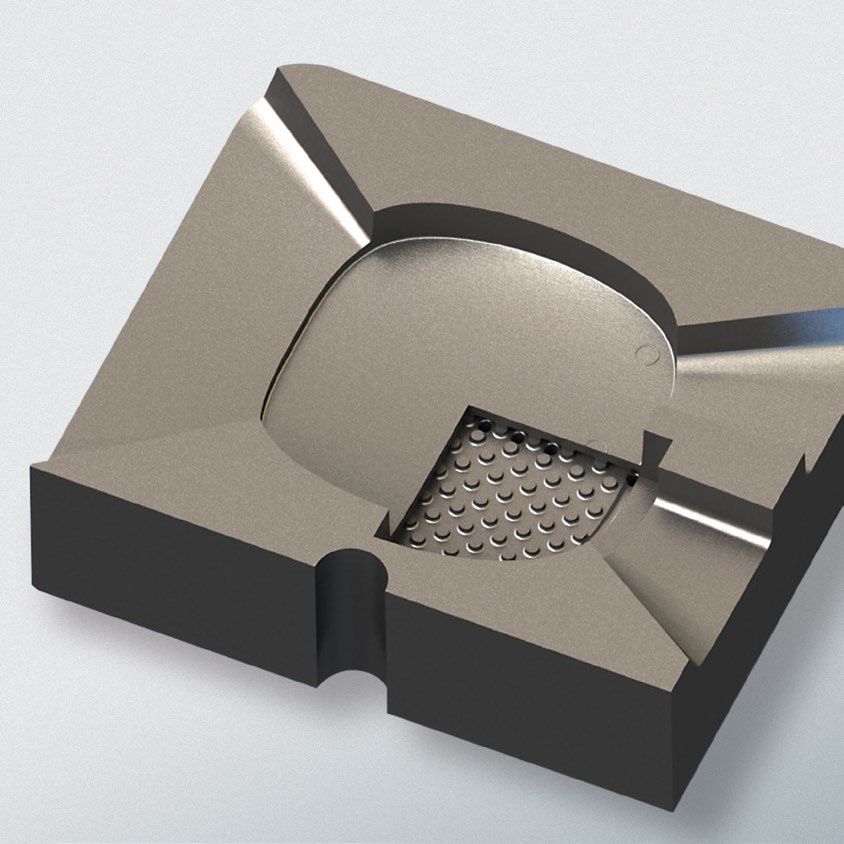
VORTEILE DES METALL-LASERSCHMELZENS
               ADVANTAGES OF METAL LASER MELTING

                 Möglichkeit zur Herstellung von komplexen, dünnwandigen Geometrien,
                 Leichtbauteilen sowie Innenkühlungen
                 Verarbeitung schwer zerspanbarer Materialien
                 Hohe Flexibilität in Geometrie und Zeit > energieeffizientes Arbeiten
                 Geringer Werkstoffabfall > Ressourceneinsparung
                 Werkzeugloses Arbeiten
                 Werkzeuglose Herstellung von Bauteilen innerhalb weniger Tage

               Mit unserem System zur zerstörungsfreien Oberflächenprüfung sind wir in der
               Lage die Bauteile zudem auf Risse, Überlappungen, Falten, Poren und Bindefeh-
               ler zu prüfen. Die Anlage entspricht dabei den Anforderungen nach Nadcap NDT.

                 Can be used to produce complex, thin-walled components, lightweight
                 structures and internal cooling systems
                 Capable of handling materials that are difficult to machine
                 High flexibility in terms of both geometry and time (energy-efficient
                 operation)
                 Low material wastage (conserving resources)
                 Tool-free operation
                 Tool-free production of components within just a few days
D-E-20200311

               Our system for non-destructive surface testing allows us to test the parts for
               cracks, overlaps, folds, porosity and lack of fusion. The system complies with the
               requirements of Nadcap NDT.                                                          3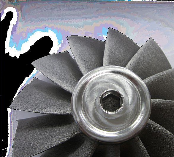
VERFAHRENSERLÄUTERUNG
    EXPLANATION OF THE PROCESS

    PROZESSKAMMER                                                                 SCHMELZVERFAHREN
    PROCESS CHAMBER                                                               MELTING PROCESS
                                                                               1 Laserstrahl                3 Erstarrte Schicht
                                                                                 Laser beam                   Hardened layer
                                                                               2 Schmelzbad                 4 Pulverschicht
      Pulverbett Powder bed                                                      Melting bath                 Powder layer

                                                                                                            Bewegungsrich-
      Belichtungseinheit Lighting unit                                                                      tung des Lasers
                                                                                                     1

                                                                                                            Direction of travel
                                                                                                            of the laser
      Laser
                                                                                      3              2                4

      Beschichter
      Coater

      Pulvervorrat
      Powder stock

      Pulvervorratsraum
      Powder stock
      compartment

                                                                                                         Entstehendes Bauteil
      Bauraum Space                                                                                       Component created

    Die 3D-CAD-Daten werden für die Herstellung der         During the manufacturing process, the 3D CAD data
    Bauteile in Querschnitte aufgeteilt. Diese werden       is divided into cross sections. These are then built up
    anschließend im Schmelzprozess aufeinander aufgebaut,   in layers during the melting process in order to create
4   wodurch das Bauteil geformt wird.                       the component.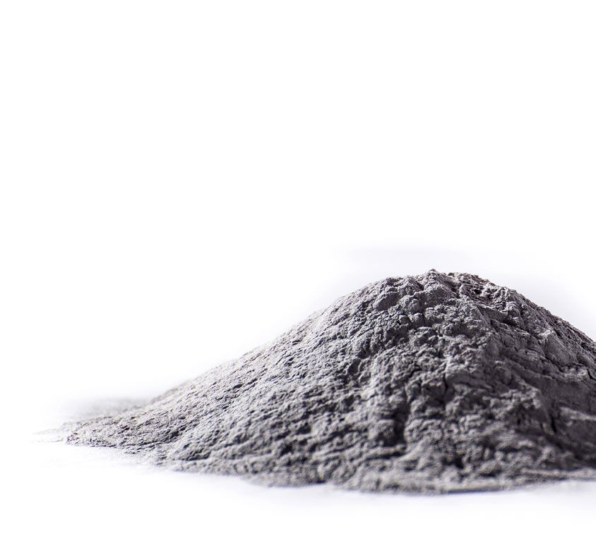
VERARBEITBARE WERKSTOFFE                                  Als Forschungs- und
                                                          Entwicklungspartner
MACHINABLE MATERIALS                                    eröffnen wir Ihnen neu
                                                                               e
                                                           Perspektiven und
                                                             Marktchancen

                                                         As your research and
 Materialien: AlSi10Mg; Scalmalloy®; 1.2343; 1.2709;
                                                       development partner, we
              TiAl6V4; Inconel® 625; Inconel® 718;      can open up new lines
              Haynes® 282 und CuCr1Zr                  of business and market
                                                        opportunities for you.

 Materials:   AlSi10Mg; Scalmalloy®; 1.2343; 1.2709;
              TiAl6V4; Inconel® 625; Inconel® 718;
              Haynes® 282 and CuCr1Zr

                                                                                   5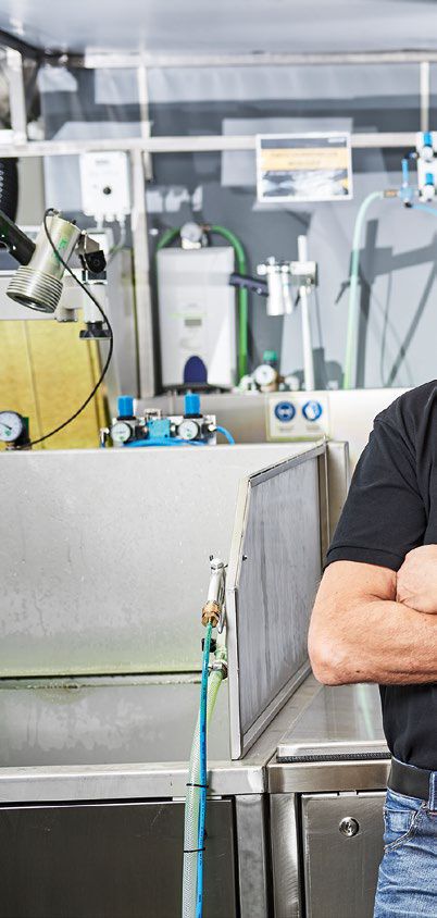
PROZESSKETTE BEI TOOLCRAFT
PROCESS CHAIN AT TOOLCRAFT

 Datenaustausch und -aufbereitung
 (inkl. FEM-Berechnung und Topologie-Optimierung)
 Fertigung
 Wärmebehandlung (u.a. im Vakuumofen nach AMS2750)
 Abtrennen (Drahtschneiden, Sägen) und Finishing
 Optische Vermessung
 Zerspantechnische Veredelung
 Taktile Vermessung
 Zerstörungsfreie Prüfung (NDT)
 Einsatz in der Praxis
 Optional: technische Oberflächen und
 heiß-isostatisches Pressen (HIP)
Data interchange and data processing
(incl. FEM calculation and topology optimisation)
Manufacturing process
Heat treatment (e.g. in vacuum furnace according
to AMS2750)
Separation (wire cutting, sawing) and finishing
Optical measuring
Finishing by machining processes
Tactile measuring
Non-destructive testing (NDT)
Use in practice
Optional: technical surfaces and
hot isostatic pressing (HIP)                        7
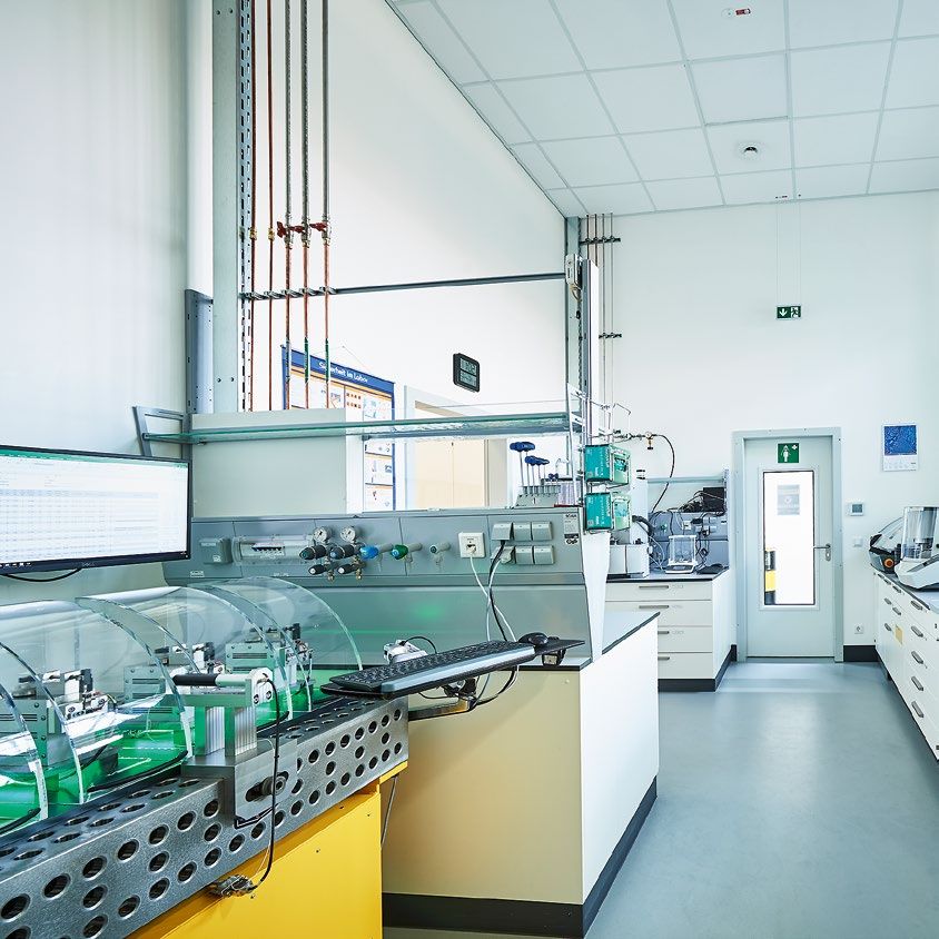
VON DER WERKSTOFFANALYSE ZUM PRÄZISIONSTEIL
    FROM MATERIAL ANALYSIS TO PRECISION PARTS

    Auf knapp 50 m² analysiert toolcraft nicht nur das eingesetzte Pulver, sondern
    auch die Eigenschaften additiv gefertigter Proben, die repräsentativ für das
    spätere Bauteil sind.

      Analyse von Gefügen
      Schliffbildanalysen
      Porositätsprüfung
      Bestimmung der Korngrößenverteilung
      Zugfestigkeitsversuche
      Ermittlung des Restsauerstoff- und Stickstoffgehalts
      Bewertung dynamischer Festigkeit mittels
      Dauerschwingversuch

    Over an area of around 50 m², toolcraft analyses the powder used and evaluates
    the properties of additively manufactured test pieces, as these are representa-
    tive of the subsequently produced components.

      Microstructure analysis
      Micrograph analysis
      Porosity analysis
      Determination of particle-size distribution
      Tensile strength testing
      Determination of residual oxygen and nitrogen content
8     Evaluation of dynamic strength using fatigue testing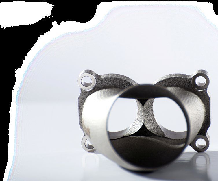
9
NACHWEISBARE QUALITÄT
     VERIFIABLE QUALITY

     Auch das Messen und Qualifizieren der gefertigten Produkte ist elementarer
     Bestandteil unserer Komplettlösungen. Ein hoch qualifiziertes Team mit langjäh-
     riger Erfahrung in diesem Bereich sowie moderne Mess- und Prüftechnik sichern
     nachweisbare Qualität – für Sie und Ihre Kunden. Vor allem bei sicherheits- oder
     zertifizierungsrelevanten Anwendungen sind die Qualität und Oberflächengüte
     von Bauteilen entscheidend. Auf einer Fläche von 75 m² bieten wir deshalb die
     Möglichkeit, Bauteile mittels Penetrant Testing (PT) und Leak Testing (LT) zerstö-
     rungsfrei auf selbst mikroskopisch kleine Risse, Überlappungen, Falten, Poren
     und Bindefehler in der Oberfläche zu überprüfen. Hierbei erfüllen wir die Anfor-
     derungen nach Nadcap NDT.

     The measuring and testing of manufactured products is an integral part of our
     comprehensive range of solutions. Our highly qualified team with many years of
     experience in this field as well as our advanced metrology and testing technology
     provide assured and documented quality – for you and your customers. The qual-
     ity and surface finish of components are pivotal, especially in applications where
     ensuring safety and gaining certifications is important. Over an area of 75 m², we
     are now able to inspect components using the non-destructive methods of pen-
     etrant testing (PT) and leak testing (LT) for even microscopic cracks, overlaps,
     folds, porosity and lack of fusion on the surface. Our work in this area fulfils Nad-
     cap NDT requirements.

10
ANWENDUNGSGEBIET PRÄZISIONSBAUTEILE
USE OF HIGH-PRECISION COMPONENTS
MOTORSPORT
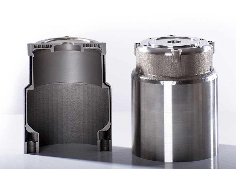
Im Bereich Motorsport fertigen wir Vor- und Kleinserien im
Entwicklungsstadium, wie z.B. Motor- und Pumpenkompo-
nenten oder Trägerbauteile. Außerdem bieten wir Bauteile
aus hochtemperaturbeständigen Werkstoffen, die beispiels-
weise in Auspuffanlagen verbaut werden.
MOTOR SPORTS
In the field of motor sports, we
manufacture pilot and small-
scale production runs of units still
in the development stage, such as
engine and pump components or
structural parts. We also produce
components made from high-
temperature-resistant materials
for installation in exhaust sys-
tems etc.
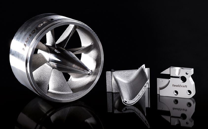
12LUFT- UND RAUMFAHRT
Im Bereich Luftfahrt fertigen wir Gehäuseteile und komplexe,
dünnwandige Strukturen für Gasturbinen. Hier werden überwie-
gend Legierungen auf Nickelbasis (z.B. Inconel® 625, Inconel® 718,
Haynes® 282) und Titanlegierungen (TiAl6V4) in Pulverform ver-
wendet. Für Space- und Defence-Anwendungen kommt aufgrund
seines geringen Wärmeausdehnungskoeffizienten Invar® 1.3912
zum Einsatz.
AEROSPACE
For the aviation sector, we manufacture housing
sections and complex, thin-walled structures
for gas turbines. The materials predominantly
used here are nickel-based alloys (e.g. Inconel®
625, Inconel® 718, Haynes® 282) and titanium
alloys (TiAl6V4) in powdered form. For space
and defence applications we use Invar®
1.3912 because of its low linear ther-
mal expansion coefficient.
13ANWENDUNGSGEBIET MEDIZINTECHNIK
MEDICAL TECHNOLOGY SOLUTIONS
Während im Motorsport oder der Luftfahrt bereits Höchstleistungen erzielt wer-
den, kann auch die Medizintechnik von der Fertigungstechnologie profitieren. Bei-
spielsweise verbessert ein 3D-gedruckter Bohrer den Erfolg einer Operation am
Knochen maßgeblich. Die im Metall-Laserschmelzverfahren hergestellte Innen-
kühlung führt zu einer Senkung der beim Bohren entstehenden Hitze um bis zu 70
Prozent. Diese konnte bislang zu Schäden am Knochen führen. Aufgrund der
Innenkühlung kann der Kühlstoff innerhalb des Werkzeuges fließen – entlang der
Helix und wieder zurück zur Werkzeugaufnahme – ohne in die Wunde zu gelangen.
INNOVATIVES KÜHLKONZEPT
INNOVATIVE COOLING CONCEPT
Kühlmitteleinlauf Coolant inlet Kühlmittelauslauf Coolant outlet
Kühlmittelreservoir
Coolant tank
14In Kooperation mit
In cooperation with
While the production technology can already be used to maximum effect in the
motorsports or aerospace sectors, the medical engineering industry can now also
benefit from it as well. For example, the use of a 3D-printed drill improves the suc-
cess of bone surgery enormously. The internal cooling system produced by means
of metal laser melting reduces the heat generated during drilling by up to 70 %. Pre-
viously, this heat was capable of damaging the bones. The internal cooling system
allows the coolant to flow inside the tool – along the helix and back to the tool
holder – without coming into contact with the wound.
15ANWENDUNGSGEBIET WERKZEUG- UND FORMENBAU
TOOL AND MOULD MAKING SOLUTIONS
FORMEINSÄTZE MIT MOULD INSERTS WITH COMPLEX
KOMPLEXEN KÜHLSYSTEMEN COOLING SYSTEMS
Formeinsätze mit komplexen Kühl- Mould inserts with complex cooling systems offer a more
systemen bieten eine effektivere effective alternative to conventional cooling channels in
Alternative zu gewöhnlichen Kühl- mould construction jobs.
kanälen im Formenbau.
Methods used:
Verwendete Methoden: Parallel cooling: With parallel cooling, in contrast to sim-
Parallelkühlung: Bei einer Parallel- ple, contour-hugging cooling, the temperature of areas is
kühlung werden, im Gegensatz zur evenly controlled without any cooling losses. This is achieved
einfachen konturnahen Kühlung, by arranging the cooling channels in a parallel configuration
Bereiche ohne Kühlverluste gleichmä- in the mould as opposed to employing the single long cool-
ßig temperiert. Dies erfolgt durch die ing channel used in simple cooling.
parallele Anordnung der Kühlkanäle in
der Form; anders als bei einfacher
Kühlung mit einem langen Kühlkanal.
16Flächenkühlung: Im Gegensatz zu Surface cooling: In contrast to cooling channels, surface
Kühlkanälen bietet die Flächenkühlung cooling enables entire geometrical areas to be cooled uni-
die Möglichkeit, ganze Geometriebe- formly. Here, a very efficient cooling effect is provided by one
reiche einheitlich zu kühlen. Dabei wird or more channel networks positioned a few millimetres
die Kühlung in Form eines oder mehre- underneath the surface of the mould.
rer Kanalnetze wenige Millimeter
unterhalb der Formoberfläche plat-
ziert, womit eine sehr effiziente Küh-
lung ermöglicht wird.
17ANWENDUNGSGEBIET WERKZEUG- UND FORMENBAU
TOOL AND MOULD MAKING SOLUTIONS
Vorteile der Formeinsätze mit komplexen Advantages of mould inserts with complex
Kühlsystemen: cooling systems:
Verbesserte Kühlkanalauslegung mit Improved cooling channel design with
gezielter lokaler Temperaturänderung targeted local temperature changes
Strömungsoptimierter Kühlverlauf > Entfall Flow-optimised cooling process (eliminating
ungenutzter Strömungszonen > gleich- unused flow zones)
mäßige Kühlung > Bauteilverzug wird Uniform cooling (component distortion
vermindert is reduced); Cooling possible up to 2 mm
Kühlung bis 2 mm an der Kontur möglich from the contour
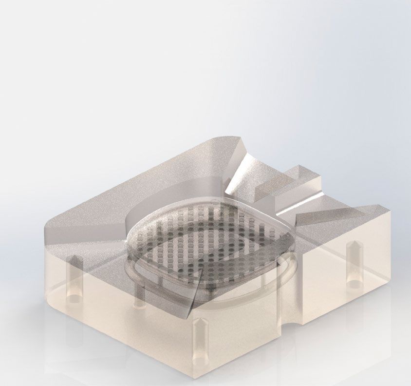
Beispiel für Flächenkühlung: Example of surface cooling:
Hybridbauverfahren Hybrid construction process
Auf einen Grundkörper aus Stahl wird die formge- The residual geometry (including the cooling
bende Restgeometrie inklusive Kühlkanal mittels channel) that gives the part its shape is welded
Metall-Laserschmelzen aufgeschweißt. Diese onto a steel base plate using metal laser melting.
Mischbauweise hat sich in vielen Fällen als die This mixed construction method has been proven
schnellste Lösung erwiesen. to be the fastest solution in many cases.
18Example of surface cooling:
hybrid construction process
(featuring surface cooling)
Beispiel für Flächenkühlung:
Hybridbauverfahren (darin
verwendet: Flächenkühlung) 19ANWENDUNGSGEBIET WERKZEUG- UND FORMENBAU
TOOL AND MOULD MAKING SOLUTIONS
FASSONSTIFTE ADJUSTABLE PINS
Fassonstifte werden im Formenbau als konturge- Adjustable pins are used in mould making as con-
bende Formeinsätze verwendet. Durch das tour-shaping mould inserts. Thanks to the metal
Metall-Laserschmelz-Verfahren ist es möglich, laser melting process, it is possible to produce
Fassonstifte mit integrierter Kühlung herzustel- adjustable pins with an integrated cooling feature.
len. Große Kühlflächen sorgen für einen idealen Large cooling surfaces ensure ideal heat transfer,
Wärmeübergang, die maximale Kühlwirkung with the maximum cooling effect being provided
ergibt sich am vorderen Ende des Kühlstifts. at the front end of the cooling pin. Moreover, opti-
Außerdem kann eine optimale Festigkeit und mum mechanical strength and rigidity of the
Steifigkeit der Formstifte durch die einteilige mould pins can be achieved thanks to the one-
Struktur von Wendel und Formstift erreicht wer- piece structure of the spiral and the mould pin.
den. Wir bieten zudem den besonderen Service We also offer the special service of fluid dynamic
einer Strömungssimulation vor Beginn der Pro- simulation before the start of production. From
duktion. Von der konstruktiven Auslegung über design to fluid-dynamical behaviour, heat
Strömungsverhalten, Wärmeabfuhr bis zur Kräf- removal and force calculation.
teberechnung.
20Bereich mit Luftkühlung in LaserCUSING ®-Technik hergestellt
Area with air cooling produced using LaserCUSING ® technology
ø 2.9 - 6.0 mm
ø 2,9 - 6,0 mm
Abluft
Exhaust air
Zuluft
Abbildungen/ Figures: CONCEPT Laser GmbH
Inlet air
21ANWENDUNGSGEBIET WERKZEUG- UND FORMENBAU
TOOL AND MOULD MAKING SOLUTIONS
VORTEILE DES METALL- ADVANTAGES OF METAL
LASERSCHMELZENS FÜR DEN LASER MELTING FOR TOOL AND
WERKZEUG- UND FORMENBAU MOULD MAKING
… für den Bereich Kunststoff-Spritzguss … for plastic injection-moulding and
und Druckguss die-casting companies
Weniger Verzug bzw. Lunker > Reduzierung Less distortion and fewer cavities
der Ausschussrate > reduced reject rate
Produktion qualitativ hochwertiger Kunst- Production of high-quality plastic and metal
stoffteile/Metallteile > Wettbewerbsvorteil parts > competitive advantage
Kürzere Zykluszeiten (ggf. Einsparung einer Shorter cycle times (there is potentially no
Spritz- bzw. Druckgussanlage sowie eines need to use an injection-moulding or
Werkzeugs bei konstanter Projektdauer) die-casting machine plus a tool but the
> Kosteneinsparung project duration remains the same)
> cost savings
… für den Endkunden
Zykluszeiteinsparungen von 20 - 30 % … for end users
> Reduktion der Stückkosten Cycle-time savings of 20 - 30 %
Qualitativ hochwertige Produkte > reduced unit costs
High-quality products
22INNOVATIVE TEMPERIERLÖSUNGEN VON TOOLCRAFT
INNOVATIVE TEMPERATURE CONTROL SOLUTIONS
BY TOOLCRAFT
mit
In Kooperation
co op er at ion with
In
FT
SCHMIDT W
Temperatur- 270.00 Flüssigkeits- 80.600
simulation 254.17 simulation 80.550
Temperature 238.33 Fluid 80.500
simulation simulation
222.50 80.450
206.67 80.400
190.83 80.350
175.00 80,300
159.17 80.250
143.33 80.200
127.50 80.150
111.67 80.100
95.83 80.050
Einheiten = C Einheiten = C
Units = CUnits = C
80.00 Units = CUnits = C
80.000 23RESTRIKTIONEN DER ADDITIVEN FERTIGUNG
ADDITIVE MANUFACTURING CONSTRAINTS
ÜBERHÄNGE
OVERHANGS
80° 70° 60° 50° 45° 40° 40° 35° 30° 25° 20° 15° 10°
Ohne Supportt Without support Mit Support With support
Kritischer Oberflächenwinkel: ≤ 45° Supportstrukturen erforderlich
Supportstruktur erforderlich Eine feste Anbindung im Randbereich
Abhängig von: wird nicht gewährleistet
Maschine/Anlage ≤ 45° supporting structures required
Material Secure adhesion at the edges is not
Qualitätsanforderungen guaranteed
Critical surface angle: ≥ 45°/ 50° keine Supportstrukturen erforderlich
Supporting structure required Einfluss des Treppenstufeneffekts ist mit steigendem
Dependent on: Winkel vernachlässigbar
Machine/equipment ≥ 45°/50° no supporting structures required
Material At a greater angle, the impact of the staircasing effect
24 Quality requirements is negligibleOberflächenrauig-
keit zunehmend mit
abflachendem
Oberflächenwinkell
The shallower the
surface angle, the
greater the surface
roughness
80° 70° 60° 50° 45° 40°
Mangelnde
Oberflächenqualität
Poor surface quality
Eingeschränkte
Prozessstabilität
Impaired process
stability
Supportstrukturen
Baurichtung Winkel ≤ 45°/50°°
Direction of
construction
Supporting
structures
40° 35° 30°
Angle ≤ 45°/50° 25ÜBERHÄNGE UND RADIEN
OVERHANGS AND RADII
R5 R4,5 R4 R3,5 R3 R2,5
R0,8 R1,5 R1 R0,6 R0,4 R0,2
Radien ≥ 3mm kritisch: Radien ≤ 3mm:
Konturgenauigkeit ungenügend Selbsttragende Geometrie
Abbildungsfehler Keine Supportstrukturen
Prozessstabilität nicht notwendig
gewährleistet Abhängig von der gewünschten
Supportstrukturen erforderlich Abbildungsgenauigkeit
Radii ≥ 3 mm critical: Radii ≤ 3 mm:
Insufficient contour accuracy Self-supporting geometry
Reproduction errors No supporting structures necessary
Process stability not guaranteed Dependent on the desired
Supporting structures required reproduction accuracy
26Glatte Fläche Raue Fläche
Smooth surface Rough surface
Raue Fläche Glatte Fläche
Rough surface Smooth surface
Baurichtung
Direction of
construction
27WANDSTÄRKEN UND ABSTÄNDE
WALL THICKNESSES & DISTANCES
Abnehmende Wandstärke
Decreasing wall thickness
Wandstärken:
Wandstärkenverteilung
möglichst einheitlich
Minimum der Wandstärke: 0,4mm
Abstände von Strukturen:
Abstände ≤ 0,3mm kritisch
Gefahr von Verstopfung
des Spaltes
Wall thicknesses:
Wall thickness distribution as
uniform as possible
Minimum wall thickness: 0.4 mm
Baurichtung
Distances from structures: Direction of
Distances ≤ 0.3 mm critical Abstand ≤ 0,3mm: construction
Risk of the gap becoming Spaltdurchgängigkeit nicht gegeben
obstructed U.a. abhängig von Bauteilstärke
Distance ≤ 0.3 mm:
No guarantee that gaps will be penetrable
28 Depends on factors such as the component thicknessBOHRUNGEN & DURCHMESSER
DRILL HOLES & DIAMETERS
Baurichtung
Direction of
construction
Durchmesser ohne Support: Diameter without support:
Ø ≥ 6 mm sehr kritisch Ø ≥ 6 mm very critical
Rundheit nicht mehr gegeben Circularity no longer guaranteed
Ø < 4 mm konturgetreu abbildbar Ø < 4 mm contours can be
Ø < 1 mm abhängig von reproduced accurately
Bohrungstiefe Ø < 1 mm dependent on the
hole depth
Baurichtung
Direction of
construction
Durchmesser mit Support: Diameter with support:
≥ 6 mm konturgetreu Ø ≥ 6 mm accurate contours
Nacharbeit erforderlich Reworking necessary
< 2 mm kein Support erforderlich Ø < 2 mm no support required 293D-Druck in Metall bei toolcraft –
Nadcap zertifiziert! Hier erhalten Sie
einen weiteren Einblick.
3D printing in metal at toolcraft –
Nadcap certified! Learn more here.
30Sie können auch lesen