Technische Informationen - TECHNICAL INFORMATION INFORMATIONS TECHNIQUES - Gotec SA
←
→
Transkription von Seiteninhalten
Wenn Ihr Browser die Seite nicht korrekt rendert, bitte, lesen Sie den Inhalt der Seite unten
Technische Informationen
TECHNICAL INFORMATION
INFORMATIONS TECHNIQUES

Montage- und Betriebsanleitung
Instructions de montage et de mise en service
Instructions for assembly and commissioning

Diese Information ist nur für den Fachmann bestimmt.
This information is only intended for the expert.
À l'usage des professionnels de la branche
Technische Daten
ELEKTRISCH HYDRAULISCH MECHANISCH
TYPE Aufnahme Zulässige Tank-
Spannung Frequenz Sicherung Saughöhe max. Gewicht netto
-Leistung Umgebungstemperatur Volumen
SP32 Leiterbahn 7m 5 l/h
230 V 50 Hz 40 W 0 - 40 °C 1,6 l 2 Kg
/01-10 bruchsicherung 4m 7 l/h
Funktion - Anwendung und Installationshinweise: 5. Elektroinstallation:
Das Gotec/Eckerle Heizöl Saugpumpenaggregat SP32-01-10 ist für Die Netzanschlussdose, 230V, muss einen Erdschutzleiter haben. Das
die Versorgung von Ölöfen und automatischen Ölbrennern mit Heizöl Gerät wird komplett, anschlussfertig mit Netzstecker nach VDE
nach DIN EN 51603-1 EL à DIN V 51603-6 EL A Bio 5 im Saugbetrieb ausgeliefert. Es Ist über eine Leiterbahnsicherung Abgesichert. Wir
bestimmt. Das Gerät saugt das Heizöl bis zu einer max. Höhe von 7m bitten Sie die Pumpe separat anzuschließen und nicht extern elektrisch,
an und füllt den eingebauten 1,6l Vorratsbehälter automatisch auf. z.B. über die Brennersteuerung, zu betreiben.
Die Versorgung kann im Zulaufbetrieb mit natürlichem Gefälle (Minimum
2%) oder im Saugbetrieb von der Ölbrennerpumpe aus erfolgen.
Die Pumpe übernimmt dann die Funktion eines Zwischenbehälters Verbraucher:
bzw. Station. Bitte kein zusätzliches Rückschlagventil sowie Filter in die Ölbrennwertgerät
unter der SP32/01-10
Saugleitung einbauen, da bereits in der Pumpe vorhanden! Sollte die
Tankarmatur des Öltanks bereits ein Rückschlagventil enthalten
ist mit einer Reduzierung der Entnahmemenge zu rechnen. Die Leis-
tungen der Pumpe werden dadurch reduziert. Der eingebaute, offene
Behälter wirkt als Ölentlüftung. Daher ist keine zusätzliche Entlüftung an
den Verbrauchern erforderlich. Die Einbaumöglichkeiten der Saugpumpe
entnehmen Sie bitte der gegenüberliegenden Spalte.
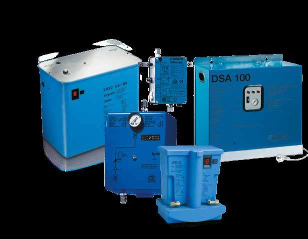
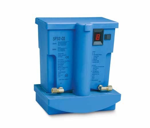
1. Technische Ausstattung:
Elektromagnetische Schwingkolbenpumpe, Filtereinsatz, Rückschlag-
ventile für die Saugleitung thermische Sicherheitsüberwachung, elektro-
nische Schwimmersteuerung mit vorprogrammierten Kontrollfunktionen,
Legende:
LCD Anzeige für Funktion und Störanzeigen, zwei Leitungsanschlüsse Verbraucher:
A. Tank
mit Schneidringverschraubungen 8 x 1, Befestigungsbügel und Material. Ölöfen unter der
B. Saugleitung Rohr Ø6/8 [mm]
Der 1,6l Vorratsbehälter sowie der Pumpenantrieb samt Verschrau- SP32/01-10
C. Ölbehälter Saugpumpe
bungen sind über der integrierten Ölauffangwanne montiert. Diese wird
D. Ölauffangwanne
durch eine Leckagesicherheitssteuerung elektronisch überwacht. Das
E. Gehäuseabdeckung
Gerät ist steckerfertig montiert und werksseitig geprüft.
F. LCD-Anzeige
2. Sicherheitsprüfung und Ausstattung: G. Starttaste
Das Gerät ist nach EN 12514-2, EN 60335-1 und EN 55015-1 geprüft. H. Netzstecker
Die Pumpe verfügt über eine Ölmangelsicherung sowie eine Lecküber- J. Absperrventile
wachung für die Sicherheitsauffangwanne. Zusätzliche, zeitgesteuerte K. Öldruckregler
Kontrollsysteme überwachen die Funktion des Pumpwerkes. L. Verbraucher
M. Rückschlagventil
3. Wandbefestigung:
Die Pumpe wird mittels beiliegendem Befestigungsbügel mit Montage-
material waagerecht (± 2%) an einer Wand befestigt. Achten Sie darauf,
dass sich die beiden Dämpfungs Gummistücke unter den jeweiligen
Kunststoffklemmlaschen der Pumpe befinden. Achten Sie auf genügend
Freiraum nach oben bzw. auf eine gute Zugänglichkeit für Wartungs-
arbeiten. WICHTIG: Die Pumpe muss min. 25cm über dem Tankni-
veau installiert sein, damit keine Zulaufdrücke entstehen können. Das
Heizöl-Druck-/Saugaggregat darf nur in trockenen und gut belüfteten
Räumen betrieben werden.
4. Rohrinstallation:
Das Gerät ist werkseitig mit Saug- und Abgangsverschraubungen für 8 x
1 Cu-Rohr NW 6 ausgestattet. Beim Anschluss der Cu-Rohre am Saug-
und Abgangstutzen ist darauf zu achten, dass keine Spannungen an
den Stutzen durch Biegen der Leitungen entstehen, und ein Gefälle von
mindestens 2% (bei Ölöfen) vorhanden ist. Die Rohrinstallation muss
fachmännisch und sorgfältig ausgeführt werden. Wenn die Saugpumpe
mehr als 3m über einem Ölofen installiert ist, muss vor dem Ofenregler
ein Öldruckminderer eingebaut werden.
Achtung :
- Beim Biegen der Leitungen dürfen keine Querschnittsverengungen
entstehen.
- Spannungen auf die Leitungsanschlüsse vermeiden.
- Bei der Montage der Leitungen ist auf Dichtigeit zu achten.
- Die gesetzlichen Richtlinien zur Rohrverlegung sind einzuhalten.
-2-
D/CH/A6. Inbetriebnahme: 9. Mögliche Störungen und Störursachen:
Nachdem die Rohranschlüsse montiert wurden, wird die Pumpe wie folgt Die Pumpe wird im Betrieb über mehrere Kontrollparameter überwacht.
in Betrieb genommen : Bei Störabschaltung sind daher folgende Überprüfungen an der Anlage
· Netzstecker (Pos. H) in Steckdose einstecken. und am Gerät vorzunehmen:
· LCD-Anzeige (Pos. F) am Gehäuse leuchtet auf. Die Zahl 8 erscheint · Ist Spannung vorhanden (leuchtet das LCD-Display ?)
auf dem Display. LCD-Anzeige - aus -Ölniveau im Voratsbehälter zu hoch.
· Schnellschluss-Absperrventil (Pos. J) zum Verbraucher schließen. · Ist das zulässige Vakuum unterschritten? LCD-Anzeige 4 oder 5
· Einschaltknopf (Pos. G) kurz drücken, Pumpe läuft an und automatisch · Ist Öl in dem Heizöltank vorhanden?
weiter. evtl. Ölmangel !! LCD-Anzeige 4 oder 5
· Nach Erreichen des oberen Schaltniveaus schaltet die Saugpumpe · Ist die Saugleitung dicht ? LCD-Anzeige 4 oder 5
automatisch ab. · Ist der Saugfilter verschmutzt ? LCD-Anzeige 4 oder 5
· Schnellschluss-Absperrventil (Pos. J) zum Verbraucher öffnen. · Ist die Ölauffangwanne gefüllt ?
· Verbraucher (Pos. L) (z.B. Ölofen, Ölbrenner) in Betrieb nehmen. Leckage oder Überlauf- LCD-Anzeige 6
· Ist die Umgebungstemperatur des Pumpwerkes höher als 60°C ?
Achtung: Bei langen Saugleitungen, sowie einem größeren Leitungs- LCD-Anzeige 7
querschnitt auf der Saugseite, empfehlen wir vor der Erstinbetriebnah- · Ist der Ölbehälter der Pumpe leer, evtl. Stromausfal l? LCD-Anzeige 0
me das Heizöl mit einer Handpumpe anzuziehen, um einen zu langen · Ist die Pumpenförderleistung noch ausreichend ?
Trockenlauf des Pumpwerkes zu vermeiden. Das Trockenlaufen des LCD-Anzeige 4 oder 5
Pumpwerkes ist elektronisch auf 10 Minuten begrenzt, danach
schaltet die Pumpe automatisch auf Störung. Nach Überprüfung der 10. Gewährleistung:
Saugleitung auf Dichtheit muss dann der Startvorgang wiederholt wer- Die Gewährleistung beträgt 12 Monaten ab Lieferdatum des Gerä-
den. tes. Bei Beanstandungen ist das defekte Gerät zusammen mit dem
Kaufnachweis (Lieferschein oder Rechnungskopie) zur Gewährleis-
7. Funktion und Störanzeige: tungsprüfung an den Lieferanten einzusenden. Diese Gewährleistung
Das Gerät ist mit einer elektronischen Funktionsanzeige (LCD-Anzeige) gilt für Materialschäden oder Herstellungsfehler und beschränkt sich auf
ausgerüstet, welche den jeweiligen Betriebszustand anzeigt. das Auswechseln oder Reparatur der defekten Teile. Arbeitskosten und
Anzeige : eventuelle sekundäre Schäden können in keinem Fall als Grundlage für
0. Ölbehälter ist leer (z.B. nach Stromausfall). eine Reklamation dienen. Bei einer nicht konformen Installation oder bei
1. Schwimmer befindet sich im Bereich Ölreserve. Nichteinhaltung der Spezifikationen oder Wartung lehnen wir jede
2. Schwimmer befindet sich auf Einschaltniveau. Haftung ab.
3. Schwimmer hat oberes Abschaltniveau erreicht (Pumpe hat abge-
schaltet). 11. Transporthinweis:
4. Wenn die Pumpe kein Öl ansaugen konnte, (Pumpenbehälter ist leer) Vor dem Versand von gebrauchten Geräten sind diese zuvor vollständig
erfolgt eine Störabschaltung nach ca 10 Minuten. zu entleeren! Transportschäden durch auslaufendes Heizöl gehen zu
5. Wenn die Pumpe das Niveau 2 nach 30 Minuten nicht erreichen Lasten des Absenders !
konnte.
6. Sicherheitsschwimmer in der Ölauffangwanne ist aktiviert. Die Sicher 12. Leistungsdiagramm:
heitswanne ist mit Öl gefüllt.
7. Temperaturfühler schaltet die Pumpe bei 60°C Umgebungstempe-
ratur automatisch ab. (z.B. bei Überlastung/Überhitzung des
Pumpwerkes).
8. Gerät ist unter Spannung
8. Wartung:
Vor Beginn der Wartungsarbeiten und Abnahme der Geräteabdeckhau-
be, immer den Netzstecker ziehen! Schnellschlussventile
(Pos. J) schließen. Die Wartung des Gerätes begrenzt sich auf die jährli-
che Reinigung des eingebauten Feinfilters (weißer Kunststofffiltereinsatz
Pos. O). Dieser befindet sich vor dem Pumpenantrieb, unter der
Geräteabdeckhaube. Der Filter kann ohne Werkzeug mittels eines Geld-
stücks ein- und ausgeschraubt werden.
Beispiele:
Bei einer Saughöhe vom 4m und einer horizontalen
Distanz von 40m, wird die Fördermenge etwa 12l/h betragen.
oder :
Bei einer Saughöhe vom 4m und einer horizontalen Distanz von 10m,
wird die Fördermenge etwa 18l/h betragen.
O
-3-
D/CH/ATechnical Features
ELECTRICAL HYDRAULIC MECHANICAL
TYPE Reseve- Gewicht netto
Voltage Frequency Wattage Fuse Max. suction height
Storage
SP32 /01- 7m 5 l/h
230 V 50 Hz 40 W 0,5 A 1,6 l 2 Kg
10 4m 7 l/h
Function, Application and Installation advice 5. Electrical Installation
The Eckerle fuel oil suction pump unit Sp32/01-10 is intended for the The main connection socket, 230V, must have an earth protective groun-
and ding. The suction pump is delivered completely ready for installation
EL according to DIN 51603 in the suction operation. The device lifts the with power supply plug according to VDE. The SP32-01 is secured by a
standard 0.5A fuse locaded on the board.
automatically. The supply to the appliance device can pursue in the
inlet operation with natural downward gradient (minimum 2%) or in the
suction operation from the oil burner pump. The pump takes over then
the function of an intermediate storage and/or a station.
line. It´s already built inside the pump. The built-in, open container works
as a oil ventilation. Therefore no additional ventilation on the consuming
device is necessary. Sketches of the installation options of the SP32-01
1.Technical Equipment
intake line, thermal safety monitoring, central detection system linked
to pre-programmed PCB, LCD display for function and breakdown
information, two line adapters with ‘O’ ring connectors 8 x 1, accessory
installation material. The 1.6l storage tank, piston pump as well as the
Legend:
hydraulic connectors are installed over the integrated secutity oil catch
A. Main oil tank
. The
B. Suction line Rohr dia. 6/8
SP32-01 arrives fully assembled and factory tested.
C. Oil tank suction pump 1,6l
D. Safety catch pan
2. Approvals and Safety Features E. Cover
F. LCD-display
- G. Start-up button
ciency safety device as well as a leakage monitoring for the safety catch H. Main electrical plug
pan. Additional, time-oprated control systems supervise the function of
the integrated piston pump. K Oil-pressure regulator
L appliance
3. Wall Mounting M Check valve
The pump is fastened horizontally by means of enclosed attachment
bracket with assembly material (± 2%) to a wall. Make sure that the
two absorption rubber pieces are located under the plastic clamping
free space upward and/or to a good accesibility for maintenance work.
The pump must be installed min. 25cm over the tank level, so that no
inlet pressures can occur. The oil lifter may only be operated in dry and
well-ventilated rooms. Outside installation are forbidden.
4. Pipe Installation
The SP32-01 is factory equipped with sucking and outlet ERMETO
screw connections for 8 x 1 CU pipes (ID 6 mm). When connecting the
CU pipes to the suction and outlet connecting piece it is to be made
certain, that no tensions at the connecting pieces result from bending the
lines, and downward gradient of at least 2% (with stove) is present. The
pipe installation must be implemented therefore expertly and carefully. If
the suction pump is installed more for than 3m over a stove, an oil pres-
sure-reducer must be inserted prior to the furnace automatic controller.
Note: - when bending the lines no cross-section contractions may
develop
- avoid over tightening on the pump connections
- when assembling the pipes pay attention to tightness
- the legal guidelines for pipe installation are to be kept
-4-
GB6. Startup Procedure 9. Possible malfunctions and breakdown causes
After the pipe connections are installed the following rules must be taken The pump is additionally monitored over several control parameters. At
under consideration: breakdown disconnection the following examinations at the intire system
- Plug main power supply (position H) into socket. (230V/50-60Hz) and at the SP32-01 are to be made:
- LCD display (position F) at the housing lights up by showing # 8. - Is electrical tension present and the LCD display shines?
- Close emergency shut-down valve (position J) to the appliance. LCD-display - off - Check fuse and replace if necessary
- Press start button (position G) briefly, pump starts and keeps running - Is oil present in the fuel oil tank? – Possible Lack of oil?
on automatically. LCD-display 4 or 5
- After reaching the upper switching level the suction pump switches off - Is the intake pipe tightened firmly? LCD-display 4 or 5
automatically. - Is the suction filter clogged? LCD-display 4 or 5
- Open emergency shut-down valve (position J) to the consuming - Is the oil security pan filled? - Leakage or overflow - LCD-display 6
device. - Is the ambient temperature of the SP32-01 higher than 60°C?
- Consumer (position L) (e.g. stove, oil burner) take into operation. LCD-display 7
- Is the oil reservoir of the pump empty, i.g. power failure? LCD-display 0
Note: In case of long runs of suction pipe or use of larger diameter - Is the flow rate of the piston pump built inside still sufficient?
pipe, we recommend priming the oil with a hand pump prior to the first LCD-display 4 or 5
startup procedure in order to avoid a dry running operation of the pump
unit. Dry running operation of the pump unit is electronically limited to 5 10. Warranty
min., afterwards the pump switches off automatically. After examination The warranty period amounts to two years after installation date of the
of the intake on tightness the starting procedure must be repeated. pump system. With a report on the defective equipment, plus proof of
purchase or installation (delivery note or copy invoice) is to be sent in for
7. LCD-Display warranty examination of the suppliers.
The SP32-01 is equipped with an LCD-display which indicates the res-
pective operating condition.
11. Transportation reference
Display:
Prior to the dispatch of used devices they have to be emptied comple-
0. Oil reservoir is empty (e.g. after power failure)
tely! Transport damages by fuel oil leakage will be at the cost of the
1. Float is in the range oil reserve (close to empty)
sender!
2. Float is the range of switching on level
3. Float achieved upper switching off level (pump has switched off)
4. If the pump could not suck in oil (pump tank is empty) a breakdown 12. Performance Diagram
disconnection takes place after approx. 5min.
5. If the pump did not reach level (2.) after 20min.
6. Safety float in the oil catch pan is activated. The safety pan is filled
with oil.
7. Temperature sensor switches the pump off automatically with 60°C
ambient temperature. (Detected inside the SP32-01), e.g. during
overloading/overheating of the pump unit.
8. SP32-01 is under electrical tension
Flow Rate
8. Maintanance
Before starting the maintenance work and dismounting the grey coloured
plastic cover (position E), always pull the main power supply plug! Ra-
pid-action valves (position J) close. Maintenance of the SP32-01 limits
itself only to the annual cleaning of the inserted fine filter (white plastic
filter cartridge located in front of the electromagnetic piston pump. The
filter can be un-/re-screwed without tool by means of a coin.
suction height
Examples:
With a suction height of 4m and a horizontal distance of 40m the flow
rate will be approx. 12l/h.
or:
With a suction height of 4m and a horizontal distance of 10m the flow
rate will be approx. 18l/h.
-5-
GBCaractéristiques techniques :
ELECTRIQUES HYDRAULIQUES MECANIQUES
TYPE Débit en fonction Températures
Contenu du
Tension Fréquence Puissance Fusible de la hauteur min. et max. réservoir
Poids Net
d'aspiration de fonctionnement
SP32 7m 5 l/h
230 V 50 Hz 40 W 0,5 A 0 - 40 °C 1,6 l 2 Kg
/01-10 4m 7 l/h
1. Descriptif: 5. Installation électrique :
La pompe aspirante SP32/01-10 intègre une pompe électromagnétique L’alimentation électrique doit être en 230V 50Hz avec mise à terre. La
pompe SP 32-01 est livrée prête à être branchée, avec une prise LNT.
moteur), une sécurité en cas de débordement, une sécurité thermique, Un fusible de 0.5A 20 x 5 est intégré sur le circuit électronique. Veuillez
toujours brancher indépendamment la pompe, elle ne doit en aucun cas
rétention, le tout commandé par un circuit électronique. être pilotée par le brûleur ou branchée sur celui-ci.
-
que. De plus, deux sécurités électroniques supplémentaires protègent
le moteur en cas de citerne vide, ou de fuite. La fonction pompe est sé-
curisée par un bac de rétention et est livrée prête à l’emploi avec câble,
en cuivre ø 6/8mm (ø 8/10mm sur demande) compris. L'entretien se
Notre pompe répond aux normes EN 12514-2, EN 60335-1 et EN
55015-1.
2. Utilisation:
La pompe aspirante SP32-01 sert à l'alimentation automatique des
poêles à mazout et brûleurs. Elle est aussi utilisable comme pompe de
DIN EN 51603-1 EL à DIN V 51603-6 EL A Bio 5 jusqu’à une hauteur
max. de 7m et remplit son propre réservoir d'une capacité
- Légende :
A. Citerne
B. Conduite
votre citerne est équipée d’un clapet anti-retour ou que votre conduite C. Réservoir 1,6l
D. Bac de rétention
des performances de la pompe et une hauteur d’aspiration plus faible E. Couvercle
que décrit dans le tableau ci-dessus. Le réservoir de la pompe étant à
l’air libre, aucun système de purge n’est nécessaire. G. Interrupteur
H. Fiche électrique
J. Robinet d’arrêt
3. Fixation de la pompe: K. Réducteur de pression
Toujours garder l'accessibilité entre le plafond et la pompe (min 20cm). L. Poêle/Brûleur
Elle doit être située au minimum 30cm M. Clapet anti-retour
au-dessus du poêle à mazout le plus élevé. Veiller à ce qu'elle soit
d'aplomb (tolérance ± 2°). La pompe doit toujours se trouver au mini-
mum 30cm au-dessus du niveau supérieur de la citerne. La pompe ne
doit être utilisée qu’à l’intérieur, dans des locaux secs et bien ventilés.
4. Installation des conduites:
Toutes les conduites (asp. et alim.) doivent être en tube de cuivre ø 6/8
mm (ø 8/10mm sur demande). Les raccords sont du type à bague cou-
pante. Pour l'alimentation par gravité des poêles, il faut une pente d’au
minimum 2% pour la conduite d’alimentation. Éviter les étranglements et
les angles fermés. Ne pas utiliser de chanvre pour
les raccords. Si la pompe est à plus de 3m au-dessus du poêle, il faut
monter un réducteur de pression 1000mm colonne d’eau devant ce
dernier. Se conformer aux prescriptions légales en vigueur.
-6-
F6. Mise en fonction de la pompe SP32/01-10 : 8. Pour tout incident imprévu :
Utiliser du fioul domestique ou éventuellement du gasoil sans adjonction · Retirer la fiche (H).
d’additifs. · Fermer le robinet d’arrêt (J).
Vérifier si le fioul de la citerne est propre. Ne pas utiliser d’additifs, ceux- · Aviser le service après vente le plus proche.
ci étant déjà incorporés à dose correcte pour améliorer la combustion, le
vieillissement et la résistance au froid. Une adjonction d’additifs supplé- 9. Entretien:
mentaires pourrait entraîner une destruction rapide de la pompe. Pour le bon fonctionnement de la pompe, il est conseillé de procéder à
Attention! un nettoyage annuel du filtre, visible en
A la mise en marche, une temporisation de 10 minutes prévient une enlevant le couvercle (E). Ce filtre se dévisse facilement à l'aide d'une
marche à sec trop importante de la pompe, il y a lieu de prévoir la pos- grande pièce de monnaie ou d’une pince
sibilité de remplir la conduite d’aspiration avec une pompe aspirante à longs becs. Pour le remontage, veiller à une étanchéité absolue.
main, si cette conduite est longue ou de section importante.
Mise en service : 10. Garantie:
1. Introduire la fiche (H) dans la prise de courant. L’affichage (F) indique A compter de la date de livraison, le fabricant accorde 12 mois de
8. la pompe est sous tension. garantie. Veuillez conserver la copie de la facture et la carte de garantie.
2. Ouvrir le robinet d'arrêt (J), et ouvrir la vanne du calorifère. Cette garantie porte sur les pièces présentant des vices de matière ou
3. Appuyer sur l’interrupteur (G), le LCD (F) va indiquer successivement des défauts de fabrication et se limite au remplacement ou à la remise
0, 1, 2 puis 3. en état des pièces défectueuses, sans qu’aucune indemnité
Fonctionnement du flotteur : ou dommages et intérêts puissent être réclamés. Nous déclinons toute
Dès que la pompe est sous tension, l’affichage digital responsabilité en cas d’installation nonconforme, de non respect des
(F) indique 8. Presser l’interrupteur (G). Le flotteur va passer par spécifications et de non entretien.
les étapes suivantes (voir schéma) :
0. est affiché jusqu’à ce que la quantité de mazout 11. Avis important:
1. le flotteur se trouve dans la réserve de 0,8l. 2. En cas de réexpédition d’un appareil, il est indispensable de vidanger
2. début de cycle. Cette valeur est affichée jusqu’en fin de cycle. correctement le réservoir avant de l’emballer.
3. fin de cycle, la pompe contient 1,6l. Alarmes : Les dommages causés par le fioul répandu au cours du transport sont à
4. sécurité basse : niveau 1 pas atteint au bout de 10 minutes. la charge de l’expéditeur.
5. sécurité intermédiaire : niveau 2 pas atteint au bout de 30 minutes.
6. sécurité haute : liquide dans le bac de rétention.
7. sécurité température : température supérieure à 60°C à l’intérieur
12. Courbes de performances:
de la pompe.
7. En cas de panne :
Lors de la mise en service, deux pannes peuvent apparaître sur l’af-
fichage :
4. Prévient la marche à sec.
Lorsque l’affichage indique 4, vérifier les points suivants :
Debit
· La conduite d’aspiration est bien vissée sur le raccord (prise d’air).
· La canne d’aspiration doit être bien plongée à l’intérieure de la citerne.
· Le filtre est propre (nettoyage une fois par année).
· Vérifier selon le tableau ci-dessous (chap.12) si la hauteur ou la lon
gueur maximale des conduites ne sont pas dépassées.
5. Vérification du bon fonctionnement de toute l’installation.
Lorsque l’affichage indique 5, vérifier les points suivants :
· Vérifier que la citerne ne soit pas vide.
· Vérifier les restrictions dans les conduites. Hauteur d´aspiration
· Vérifier les points mentionnés en cas d’alarme 4.
En fonctionnement, la pompe comporte deux sécurités :
6. Sécurité du bac de rétention.
Lorsque l’affichage indique 6, il y a eu une fuite dans le bac de rétention
(D). Vérifier les points suivants : Exemple:
· Vérifier d’où la fuite provient, si ce sont les raccords (in, out), bac Pour une hauteur de 4m et une distance de 40m,
percé, trop-plein*. le débit sera de 12l/h.
· Avant de remettre la pompe en marche, il faut vider le bac de rétention.
(Dévisser les quatre vis qui se trouvent en dessous du bac). Pour une hauteur de 4m et une distance de 10m,
*Attention si la fuite vient du trop-plein, cela signifie que la pompe ne le débit sera de 18l/h.
s’est pas arrêté une fois le niveau haut atteint (point 3 lors
de la mise en service). Débrancher la fiche (H), vérifier que le flotteur de
travail ne soit pas bloqué puis refaire une mise en service.
7. Sécurité en cas de température élevée (incendie, surchauffe etc).
L’alarme 7 s’affiche lorsque la température ambiante est supérieure à
60 °C. Si cette inscription apparaît, examiner d’où provient cette chaleur.
Pour redémarrer la pompe après chaque panne il faut quittancer en
pressant le bouton de mise en marche (G), si vous avez du mettre la
pompe hors tension il faut faire une mise en service (voir chapitre 6).
-7-
FFür weitere Informationen besuchen Sie bitte unsere Internetseite unter:
For more informations visit our web-site:
www.eckerle.com
www.gotecpumps.com
Stand:07/17
Eckerle Technologies GmbH ■ Otto-Eckerle-Str. 6/12A ■ D-76316 Malsch ■ Tel +49 (0) 7246-9204-0 ■ Fax +49 (0) 7246-9204-44
Gotec SA ■ Route de Mangold 11 ■ CH-1958 St-Léonard ■ Tel. +41(0)27 205 72 05
info@gotec.ch www.gotec.chSie können auch lesen