DE 9 XL ELEKTROHEIZER - BEDIENUNGSANLEITUNG USER MANUAL / MANUEL D'UTILISATION DE - OXOMI
←
→
Transkription von Seiteninhalten
Wenn Ihr Browser die Seite nicht korrekt rendert, bitte, lesen Sie den Inhalt der Seite unten
www.heylo.de
Stand: 01/2021
Art.-Nr. 1 101 917
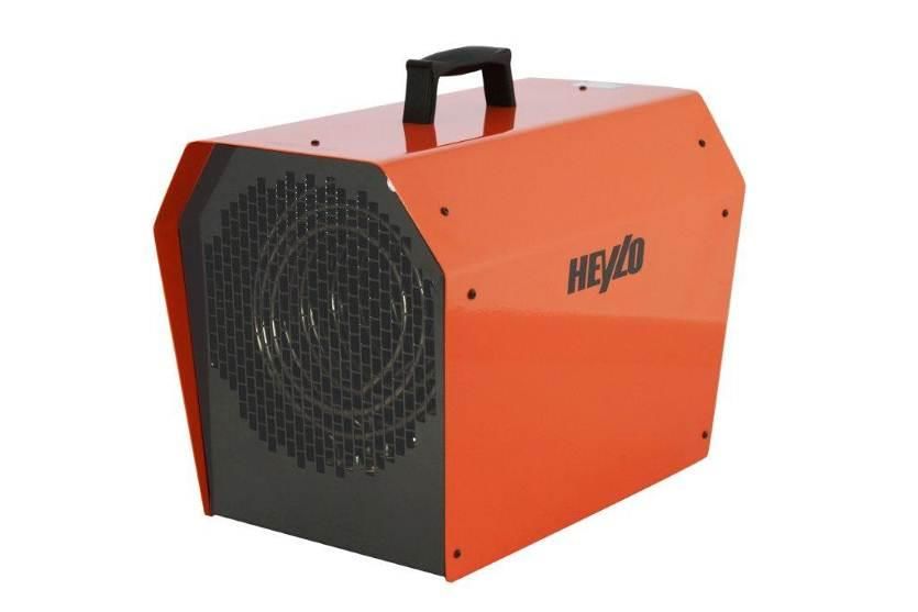
DE 9 XL ELEKTROHEIZER
BEDIENUNGSANLEITUNG
USER MANUAL / MANUEL D‘UTILISATION
DE Elektroheizer
EN Electric Heater
FR Appareils de chauffage électriquesEG-Konformitätserklärung IIA
Gemäß der EG-Richtlinie für Maschinen 2006/42/EG
Für Gerätebaureihe: Elektroheizgeräte
Typ: DE 9 XL
HEYLO GmbH, Im Finigen 9, 28832 Achim, erklärt, dass die genannten Maschinen, wenn sie gemäß
Bedienungsanleitung und nach den anerkannten Regeln der Technik installiert, gewartet und gebraucht werden,
den grundlegenden Sicherheits- und Gesundheitsanforderungen der Richtlinie „Maschinen“, sowie folgenden
Bestimmungen und Normen entsprechen.
Zutreffende EG-Richtlinien:
Maschinenrichtlinie 2006/42/EG
Niederspannungsrichtlinie 2014/35/EU
EMV – Richtlinie 2014/30/EU
Bei eigenmächtigen Veränderungen der Maschinen verliert die Erklärung ihre Gültigkeit.
Angewandte Normen:
DIN VDE 0700 Teil 1 und Teil 30
DIN EN 55014-1:2012-05
EN 60 335-1
EN 60 335-2-30
Achim, 18.07.2016 …………………….…….……………..
Dr. Thomas Wittleder
- Geschäftsführer -
----------------------------------------------------------------------------------------------------------------------------------------
Inhaltsverzeichnis
1. Allgemeines ............................................................................................................................. 3
2. Sicherheitshinweise ................................................................................................................. 3
3. Betrieb ..................................................................................................................................... 3
4. Aufstellrichtlinien ..................................................................................................................... 4
5. Technische Daten ................................................................................................................... 5
6. Fehlersuche und –behebung................................................................................................... 5
7. Schaltplan ................................................................................................................................ 6
8. Ersatzteilliste ........................................................................................................................... 7
2 DE1. Allgemeines
ACHTUNG: Vor Inbetriebnahme unbedingt lesen!
Bitte beachten Sie sorgfältig die Hinweise in der Bedienungsanleitung. Bei Nichtbeachtung erlischt der
Gewährleistungsanspruch. Für Schäden bzw. Folgeschäden die daraus entstehen, übernimmt der
Hersteller keine Haftung.
Die Elektroheizer der DE-Reihe sind leichte, gut transportable Warmlufterzeuger. Die Heizleistung des
DE 9 XL ist 2-stufig einstellbar, die Luftmenge nicht. Ein Anschluss von Luftleitungen bei dem Gerät ist
nicht zulässig. Das Gerät kann im Lüftungs- und Heizmodus betrieben werden.
Der Elektroheizer ist geeignet zur Punktbeheizung (z.B. von Maschinen oder von Arbeitsplätzen) und
zur Beheizung von geschlossenen Räumen. Er ist für den waagerechten Betrieb konstruiert.
Außerdem kann das Gerät zum Belüften von kleinen Bereichen eingesetzt werden
Das Gerät ist mit einem Thermostat ausgerüstet. (Schaltbereich + 5°C bis + 40°C)
Ein externes Raumthermostat kann nicht angeschlossen werden.
2. Sicherheitshinweise
▪ Um eine Überhitzung oder eine Brandgefahr zu vermeiden, decken Sie die Heizung niemals ab.
▪ Schließen Sie das Gerät nur an geerdete Steckdosen an, die der Spannung auf dem Typenschild
angegeben ist entspricht.
▪ Kinder sollten beaufsichtigt werden, um sicherzustellen, dass sie nicht mit dem Gerät spielen.
▪ Sollten Sie Beschädigungen am Gerät oder am Netzkabel feststellen, nehmen Sie das Heizgerät
sofort außer Betrieb.
▪ Verwenden Sie das Heizgerät nicht im Bereich einer Badewanne, Dusche oder in der Nähe eines
Schwimmbeckens.
3. Betrieb
Netzanschluss: 400 V / 50 Hz / 16 A CEE
Inbetriebnahme des Gerätes:
1. CEE-Stecker in die geeignete Steckdose stecken.(Nullleiter erforderlich)
2. Wahl der Funktion (Heizen oder Kalt-Lüften)
0 MIN
MAX
1 2
Schalter 1 (Heizen)
0 = Aus
1 = Kalt-Lüften
2 = 4500 W
3 = 9000 W
Wenn der Schalter 1 auf Betriebsart Heizen geschaltet ist, werden die Heizungen automatisch bei
Erreichen der eingestellten Temperatur (Schalter 2) abgeschaltet.
Der Ventilator läuft für eine bessere Luftzirkulation weiter.
3 DENach dem Abschalten läuft der Ventilator noch solange nach, bis keine Restwärme mehr vorhanden
ist (Nachkühlfunktion).
Wenn der Schalter 1 auf Lüften eingeschaltet ist, ist nur der Lüftermotor in Betrieb.
Schalter 2 (Temperatur-Thermostat)
In der Betriebsart Heizen ist eine Regelung der Raumtemperatur zwischen 5° und 40°C möglich.
Abschalten
Nach dem Ausschalten, muss solange gewartet werden, bis der Ventilator sich abschaltet. Erst dann
darf der Netzstecker gezogen werden.
ACHTUNG: Da die Heizelemente in der Fertigung mit einem Schutzölfilm versehen werden, entsteht
beim ersten Einschalten für eine kurze Zeit eine leichte Rauchentwicklung. Dieser Rauch ist normal
und nicht gesundheitsgefährdend.
4. Aufstellrichtlinien
1. Aufstellort
Die Geräte dürfen nicht an Orten betrieben werden, an denen zündfähige Gas-, Luft- oder Staub-
Luft-Gemische auftreten (z.B. Tankstellen, Lackierereien usw.) und auch nicht dort, wo sie
brennbare Kleinteile ansaugen, die an der Heizspirale entzündet und glühend ausgeblasen werden
können (z.B. Stroh, Papier, Sägespäne usw.).
Das Gerät darf nicht an Luftkanäle oder -schläuche angeschlossen werden.
Das Gerät sollte nicht starken Staubemissionen ausgesetzt werden. Staubablagerungen auf dem
PTC Heizelement können in Verbindung mit Feuchtigkeit einen Kurzschluss verursachen.
2. Aufstellung
Elektroheizer dürfen nicht in unmittelbarer Nähe von Badewannen, Duschen, Waschbecken oder
Schwimmbecken betrieben werden.
3. Sicherheitsabstände zu brennbaren Teilen:
Seitlich: 0,60 m Ausblasseite: 2,00 m
Ansaugseite: 0,20 m nach oben: 2,00 m
Die Elektroheizer dürfen nicht mit Textilien bedeckt werden!
Fußboden und Decke müssen feuerhemmend sein. Ansaug- und Ausblasstutzen dürfen nicht
verengt werden.
4. Bei Verwendung auf dem Bau müssen die Sicherheitsrichtlinien der Bau-Berufsgenossenschaften
eingehalten werden.
5. Bei Verwendung in der Landwirtschaft gelten die Vorschriften der landwirtschaftlichen
Berufsgenossenschaften und Sachversicherer.
6. Gesetzliche Vorschriften: folgende Vorschriften sind bei Aufstellung und Inbetriebnahme zu
beachten:
Arbeitsstättenverordnung §§ 5 und 14
Arbeitsstättenrichtlinie ASR 5
Unfallverhütungsvorschriften VBG 43
erhältlich bei: Deutsches Informationszentrum für technische Regeln (DITR) im DIN,
Burggrafenstraße 6, 10787 Berlin).
7. Das Gerät darf nicht unter Wandsteckdosen betrieben werden.
8. Das Gerät darf nicht ohne Aufsicht durch eine Programmschaltuhr betrieben werden.
4 DE5. Technische Daten
Modell DE 9 XL
Gesamtleistung W 9000
Heizleistung (Stufe 1 / 2) W 4500 / 9000
Motorleistung W 52
Regelungsmöglichkeit °C +0° bis + 40°
Spannung V 400
Strom ( Stufe 1 / Stufe 2) A 6,5 / 13
Luftmenge m³/h 550
IP Klasse 24
Länge / Breite / Höhe mm 466 / 322 / 420
Gewicht kg 14,5
6. Fehlersuche und –behebung
FEHLER URSACHE BESEITIGUNG
Gerät läuft nicht an 1. Hauptschalter ausgeschaltet Prüfen, bis zu welcher Stelle Strom
2. Sicherungen der Hausinstallation vorhanden ist. Defekt beseitigen.
ausgelöst.
3. Interne Sicherung (3A) hat
ausgelöst.
4. Stecker aus Hauptschaltertafel
oder Verlängerungskabel gezogen.
5. Zuleitung defekt.
6. Netzabschaltung Warten bis Strom wiederkommt.
Absicherung überprüfen.
7. Fehlerstrom-Schutz-Schalter der Heizspirale reinigen (evtl. mit
Hausinstallation hat ausgelöst. Pressluft), ansonsten zur
Reparatur.
Gerät könnte mit Feuchtigkeit in
Berührung gekommen sein. Falls
ja, vor Betrieb ausgiebig trocknen
lassen
8. Heizspirale defekt. Gerät zur Reparatur
Gerät heizt, Ventilator 9. Ventilator defekt Gerät zur Reparatur
läuft nicht
Ist das Gerät durch das Netzkabel mit Strom versorgt, dürfen die Arbeiten an der
elektrischen Anlage nur von elektrischem Fachpersonal bzw. einer elektrisch
unterwiesenen Person entsprechend VBG 4 ausgeführt werden.
Bitte lassen Sie Reparaturarbeiten der Elektro-Geräte nur von Servicepartnern der Firma HEYLO
durchführen.
Außerbetriebnahme und Entsorgung des Gerätes
Das Gerät ist für langjährigen Betrieb ausgelegt.
Wenn es entsorgt werden soll, hat dies gemäß der aktuellen einschlägigen gesetzlichen
Bestimmungen in umweltschonender Weise zu erfolgen.
5 DE7. Schaltplan
0 – 40°
140°
110°
6 DE8. Ersatzteilliste
Pos. HEYLO Art.-Nr. Bezeichnung
1 1760911 Sicherung
2 1760912 Lüftergitter Ausblasseite
3 1760913 Temperaturbegrenzer Ausblasseite
4 1760914 Halterung Temperaturbegrenzer
5 1760915 Heizelement
6 1760916 Isoliermantel
7 1760917 Griff
8 1760918 Gehäuse
9 1760919 Lüfterflügel
10 1760920 Lüftermotor
11 1760921 Lüftergitter Ansaugseite
12 1760922 Sensorhalterung
13 1760923 Einstellbares Thermostat
14 1760924 Knopf für Thermostat
15 1760925 Schraubeinsatz Netzkabel
16 1760926 Lüfterschalter
17 1760927 Mitnehmer Lüfterschalter
18 1760928 Adapterring Lüfterschalter
19 1760929 Netzkabel (ohne Stecker)
20 1760930 Netzstecker (5-polig)
21 1760931 Temperaturbegrenzer
22 1760932 Nachlauf Thermostat
23 1760935 Schütz
24 1760940 Isolierplatte
25 1760939 Hutschiene für Schütz
26 - -
27 1760933 Verbindungsleiste
28 1760934 Halterungsplatten
29 1760936 Bodenplatte
30 1760937 Gummifuß
31 1760938 Befestigungsschraube
7 DEEC Declaration of Conformity IIA
In conformity with EC Machine Directive 2006 / 42 / EC
For unit series: Electric heating appliances
Type: DE 9 XL
HEYLO GmbH of Im Finigen 9, D-28832 Achim, Germany, declares that, if they are fitted, maintained and used in
conformity with the operating instructions and the generally accepted engineering standards, the machines
mentioned are in keeping with the fundamental safety and health requirements of the “Machine Ordinance” as
well as with the regulations and standards mentioned hereinafter.
Applicable EC directives:
EC Machinery Directive 2006/42/EG
Low Voltage Directive 2014/35/EU
EMC Directive 2014/30/EU
In case of unauthorised changes of the machine, the directives shall forfeit their validity.
Applied standards:
DIN VDE 0700 Part 1 and Part 30
DIN EN 55014-1:2012-05
EN 60 335-1
EN 60 335-2-30
Achim, 18 July 2016 …………………….…….…………….
Dr. Thomas Wittleder
- Managing Director -
----------------------------------------------------------------------------------------------------------------------------- -
Table of contents
1. General information ................................................................................................................. 9
2. Safety instructions ................................................................................................................... 9
3. Operation ................................................................................................................................. 9
4. Installation guidelines ............................................................................................................ 10
5. Technical Data ...................................................................................................................... 11
6. Troubleshooting ..................................................................................................................... 11
7. Circuit diagram ...................................................................................................................... 12
8. Spare parts list....................................................................................................................... 13
8 EN1. General information
CAUTION: Read carefully before starting up!
Please observe the notes in the operating instructions carefully. In case of non-observation, the
warranty claims will become void. The manufacturer shall not be liable for any damage and/or
consequential damage resulting.
The DE series electric heaters are light, easily transportable producers of warm air. The heat output of
the DE 9 XL can be adjusted at 2 levels. The amount of air cannot be adjusted. Connecting air pipes
to the device is not permitted. The device can be used for ventilation and heating.
The electric heaters are suitable for spot heating (e.g. of machines or work places) and for heating
closed rooms. They have been designed to be used in a horizontal position.
The device may as well be applied for ventilation of small areas.
The appliance is fitted with a thermostat (Switching range + 5°C to + 40°C)
An external room thermostat cannot be connected to it.
2. Safety instructions
▪ To avoid overheating or a fire hazard, do not cover the heating from.
▪ Do not connect the appliance to the mains power socket if the voltage given on the rating plate
differs from the mains voltage.
▪ Children should be supervised to ensure that they do not play with the appliance. If the appliance
is damaged, do not use it any more.
▪ If you notice any damage to the unit or power cord, remove the heater off immediately.
▪ Do not use the heater in a bathtub, shower or near a swimming pool
3. Operation
Mains connection: 400 V / 50 Hz / 16 A CEE
Starting up:
1. CEE-plug into the suitable socket. (Neutral required)
2. function choice (heating or cold-ventilation)
1 2
Switch 1 (heating)
0 = off
1 = cold-ventilation
2 = 4500 W
3 = 9000 W
When the switch 1 is connected to a heating mode, the heater will automatically shut off when
reaching the set temperature (switch 2). The fan continues operating for better air circulation.
9 ENAfter shutting off, the fan will continue until no more residual heat is present (after-cooling function).
When the switch 1 is switched on ventilation is, only the fan motor.
Switch 2 (temperature thermostat)
In the heating mode to regulate the room temperature between 5°C and 40°C is possible
Switching off
After switching off, then have to wait until the fan turns off. Only then should the plug be pulled.
4. Installation guidelines
1. Place of installation
The appliances cannot be operated at place where there are ignitable gas, air or gas/air combinations
(e.g. petrol pumps, paint workshops, etc.) and also not where they can suck in small combustible
parts, that can be lighted up at the heating coil and blown out as glowing sparks (e.g. straw, paper,
sawdust and wood shavings, etc.)
The appliance cannot be connected to air conduits or hoses. The device should not be exposed to
heavy dust emissions. Dust deposits on the PTC heating element can cause a short circuit in
connection with humidity.
2. Installation
Electric heaters cannot be operated in the immediate proximity of bathtubs, wash basins or
swimming pools.
3. Safety distances to combustible parts:
On the side: 0.60 m Blow out side: 2.00 m
Suctioning side: 0.20 m Upwards: 2.00 m
Do not cover electric heaters with textiles!
Floors and ceilings must be fire resistant. Suctioning and blowing out pipes should not be
narrowed.
4. When using on a construction site, the safety guidelines of the professional construction
associations must be maintained.
5. When using in agriculture, the regulations of the agricultural professional associations and
property insurers apply.
6. Legislation: the following regulations must be observed when installing and starting up:
Work place ordinance §§ 5 und 14
Work place directive ASR 5
Accident prevention regulations VBG 43
available at: German Information Centre for Technical Regulations (DITR) at DIN,
Burggrafenstraße 6, 10787 Berlin).
7. The appliance cannot be operated under wall sockets.
8. The appliance cannot be operated by a programmable timer without supervision.
10 EN5. Technical Data
Type DE 9 XL
Total output W 9000
Heat output (level 1 / level 2) W 4500 / 9000
Motor output W 52
Control possibility °C 0° - 40°
Voltage V 400
Electricity (ventilate / level 1 / level 2) A 6,5 / 13
Air volume m³ / h 550
IP class 24
Length x width x height mm 466 / 322 / 420
Weight kg 14,5
6. Troubleshooting
ERROR CAUSE SOLUTION
Appliance does not start 1. Main switch switched off Check up to what point
up 2. Indoor fuses tripped. electricity is available.
3. Internal fuse (13A) has been Repair defect.
activated.
4. Plug has been pulled out of the
main switch panel or extension
cable.
5. Supply line defective.
6. Mains switched off Wait until electricity returns.
Check safeguards.
7. Safety temperature limiter tripped Appliance was overheated.
Repair source of error and
the appliance will switch
itself on again after waiting
for a while.
8. Indoor residual-current-circuit Clean heating coil (possibly
breaker trips. with compressed air)
otherwise send it to be
repaired.
Appliance could have come
into contact with moisture. If
yes, let it dry thoroughly
before operating it.
9. Heating coil defective. Send appliance to be
repaired
Appliance heats up, fan 10. Fan defective Send appliance to be
does not run repaired
If the appliance is supplied with electricity by the mains cable, work to the electrical
system can only be carried out by specialist electrical staff or a person trained in
electrical appliances in accordance with VBG 4.
Please only get repair work to the electrical appliance done by HEYLO service partners.
Discontinuing use and disposal of the appliance
The appliance has been designed for long term use.
If it has to be disposed of, please do so in accordance with the current relevant laws in an environment
friendly manner.
11 EN7. Circuit diagram
0 – 40°
140°
110°
12 EN8. Spare parts list
Pos. HEYLO - Art.-No. Bezeichnung
1 1760911 Fuse assemble
2 1760912 Front grill assemble
3 1760913 Protector 1
4 1760914 Fixed board for thermostat
5 1760915 Heating element
6 1760916 Air ventilator
7 1760917 Handle
8 1760918 Haousing
9 1760919 Fan blade
10 1760920 Motor
11 1760921 Back grill assemble
12 1760922 Sensor supporter
13 1760923 Adjustable thermostat
14 1760924 Knob assemble
15 1760925 Fixed head for cable
16 1760926 Switch
17 1760927 Fixed part für switch
18 1760928 Ring
19 1760929 Cable
20 1760930 Five pin plug
21 1760931 Protector 2
22 1760932 Time-delay thermostat
23 1760935 AC contactor
24 1760940 Insulation board
25 1760939 Rail
26
27 1760933 Connection terminal
28 1760934 Fixed board for relay
29 1760936 Bottom board
30 1760937 Rubber feet
31 1760938 Screw
13 ENDéclaration de conformité CE IIA
Selon la diréctive CE pour les machines 2006/42/CE
Pour la série d‘appareils : Appareils de chauffage électriques
Type: DE 9 XL
HEYLO GmbH, Im Finigen 9, 28832 Achim, déclare que les machines nommées répondent aux exigences
fondamentales de sécurité et de santé de la directive „machine“ ainsi qu’aux dispositions et normes suivantes
lorsqu’elles sont installées, entretenues et utilisées conformément au mode d’emploi et aux règles reconnues de
la technique.
Directives CE pertinentes:
Directive des machines 2006/42/EG
Directive de basse tension 2014/35/EU
Directive CEM 2014/30/EU
La déclaration perd sa validité en cas de modifications arbitraires des machines.
Normes appliquées :
DIN VDE 0700 partie 1 et partie 30
DIN EN 55014-1:2012-05
EN 60 335-1
EN 60 335-2-30
Achim, 18.07.2016 …………………….…….……………..
Dr. Thomas Wittleder
- Directeur –
----------------------------------------------------------------------------------------------------------------------------- --
Table des matières
1. Généralités ............................................................................................................................ 15
2. Sécurité.................................................................................................................................. 15
3. Fonctionnement ..................................................................................................................... 15
4. Directives de mise en place................................................................................................... 16
5. Données techniques .............................................................................................................. 17
6. Recherche et résolution des erreurs ..................................................................................... 17
7. Schéma de montage ............................................................................................................. 18
8. Liste des pièces de rechange ................................................................................................ 19
14 FR1. Généralités
ATTENTION:
À lire impérativement avant la mise en service !
Veuillez observer strictement les remarques mentionnées dans le manuel d’utilisation. La prétention à
la garantie est exclue en cas de non-observation de la notice d’utilisation. Le fabricant n’assume
aucune responsabilité pour les dommages ou les dommages consécutifs pouvant résulter de ce non-
respect.
Les chauffages électriques de la série DE sont des générateurs d’air chaud légers et transportables.
La puissance de chauffage du DE 9 XL est réglable à 2 niveaux, pas la quantité d‘air. Le
raccordement de conduite à air sur l‘appareil n’est pas autorisée. L’appareil peut être pratiqué au
mode de ventilation et chauffage.
Les chauffages électriques sont appropriés au chauffage ponctuel (par exemple de machines ou de
postes de travail) et pour le chauffage de pièces closes. Ils sont construits pour un fonctionnement
horizontal.
En outre, l’appareil peut être utilisé pour l’aération de petites zones.
L’appareil est muni d’un thermostat (domaine de commutation + 5°C à + 40°C).
Un thermostat de pièce externe ne peut pas être raccordé.
2. Sécurité
▪ Afin d'éviter une surchauffe ou un risque d'incendie, ne couvrez pas le radiateur.
▪ Brancher l'équipement dans une mise à la terre débouchés que la tension indiquée sur l'étiquette.
▪ Les enfants doivent être surveillés pour s'assurer qu'ils ne jouent pas avec l'appareil.
▪ Si vous constatez des dommages à l'appareil ni le câble d'alimentation, retirez le radiateur
immédiatement.
▪ Ne pas utiliser l'appareil dans une baignoire, une douche ou près d'une piscine.
3. Fonctionnement
Raccordement au réseau 400 V / 50 Hz / 16 A CEE
Mise en service:
1. Mettre la fiche dans la prise de courant appropriée.
2. Choix de fonction (chauffage ou ventilation d’air froid)
1 2
Commutateur 1 (chauffage)
0 = Arrêt
1 = ventilation d’air froid
2 = 4500 W
3 = 9000 W
15 FRLorsque le commutateur 1 est relié à un mode de chauffage, le chauffage s'arrête automatiquement
lorsqu'il atteint la température de consigne (bouton 2). Le ventilateur continue de tourner pour une
meilleure circulation d’air.
Après la mise à l’arrêt, le ventilateur continue de tourner jusqu'à ce qu'il n'y ait plus de chaleur
résiduelle présente (fonction d’après-refroidissement).
Lorsque le commutateur est une tension de ventilation est, seulement le moteur de ventilateur.
Commutateur 2 (température thermostat)
Dans le mode de chauffage pour réguler la température ambiante entre 5 ° et 40° C est possible.
Arrêt
Après la mise hors tension, puis à attendre jusqu'à ce que le ventilateur s'éteint. C'est seulement alors
que la fiche soit tiré.
4. Directives de mise en place
1. Lieu d‘installation
Les appareils ne peuvent pas être utilisés dans des lieux où des mélanges inflammables de gaz, d’air
ou d’air poussiéreux se produisent (par exemple des stations-services, vernisseries, etc.…) et aussi là
où ils aspirent des particules inflammables qui s’enflamment sur la spirale chauffante et peuvent être
soufflées rougeoyantes (par exemple paille, papier, sciure, etc.…).
L’appareil ne peut pas être raccordé à des canaux ou des tuyaux à air.
Le dispositif ne doit pas être exposé à des émissions de poussières lourdes. Les dépôts de poussière
sur l'élément chauffant PTC en combinaison avec l'humidité peuvent causer un court-circuit.
2. Mise en place
Les chauffages électriques ne doivent pas être utilisés à proximité immédiate de baignoires,
douches, lavabos ou bassins.
3. Distance de sécurité avec des pièces inflammables:
Latéral: 0,60 m Coté de soufflerie: 2,00 m
Coté d‘aspiration: 0,20 m Vers le haut: 2,00 m
Les chauffages électriques ne doivent pas être couverts par des textiles!
Les sols et couvertures doivent être résistant au feu. Les supports d’aspiration et de soufflerie ne
doivent pas être resserrés.
4. En cas d’utilisation sur un chantier, les directives de sécurité de l’association professionnelle du
bâtiment doivent être respectées.
5. En cas d’utilisation dans l’agriculture, les règlements de l’association professionnelle de
l’agriculture et des assureurs sont valables.
6. Règlements légaux: Les règlements suivants doivent être respectés lors de l‘installation et la mise
en service:
- Ordonnance des lieux de travail §§ 5 et 14
- Directive des lieux de travail ASR 5
- Règlement e prévention des accidents VBG 43
- Disponibles au: Centre allemand d’information pour les règles technique (AIRT) en DIN,
Burggrafenstraße 6, 10787 Berlin).
7. L’appareil ne doit pas être utilisé sous une prise murale.
8. L’appareil ne doit pas être utilisé sans la surveillance d’une horloge programmable.
16 FR5. Données techniques
Type DE 9 XL
Puissance totale W 9000
Puissance de chauffage (niveau 1 / 2) W 4500 / 9000
Puissance du moteur W 52
Possibilité de réglage °C 0° - 40°
Tension V 400
Courant (ventiler / niveau 1 / niveau 2) A 6,5 / 13
Quantité d‘air m³ / h 550
classe de protection IP 24
longueur x largeur x hauteur mm 466 / 322 / 420
Poids kg 14,5
6. Recherche et résolution des erreurs
ERREUR CAUSE RESOLUTION
L’appareil ne 1. L’interrupteur principal est éteint Vérifier jusqu’à quelle position le
marche pas 2. Le fusible de l‘installation est courant est disponible. Résoudre le
déclenché. défaut.
3. Fusible interne (13A) est libéré.
4. La prise est retirée du tableau de
l‘interrupteur principal ou de la
rallonge.
5. Ligne défectueuse.
6. Arrêt du réseau Attendre jusqu’à ce que le
courant revienne.
Vérifier la protection.
7. Le limiteur de température de L’appareil est en surchauffe. Eliminer la
sécurité est déclenché source de l’erreur et l’appareil
redémarre automatiquement après un
temps d’attente.
8. L’interrupteur de protection de Nettoyer la spirale chauffante
courant défectueux de l’installation (éventuellement avec de l’air
est déclenché. comprimé), sinon le faire réparer.
L'appareil peut se retrouver en contact
avec l‘humidité. Si c’est le cas, le faire
sécher longtemps avant utilisation
9. Spirale chauffante défectueuse Faire réparer l‘appareil
L’appareil chauffe, 10. Ventilateur défectueux Faire réparer l‘appareil
le ventilateur ne
marche pas
Si l’appareil est alimenté en courant par un cordon électrique, les travaux sur le dispositif
électrique ne peuvent être effectués que par des électriciens qualifiés ou une personne
formée à l’électricité selon VBG 4.
Ne laissez faire les travaux de réparation des connexions électriques l’appareil que par des
partenaires de la société HEYLO.
Mise hors service et collecte de l‘appareil
L’appareil est pensé pour un fonctionnement de nombreuses années.
Lorsqu’il doit être collecté, cela doit être effectué de manière respectable pour l’environnement selon
les dispositions spécialisées légales actuelles.
17 FR7. Schéma de montage
0 – 40°
140°
110°
18 FR8. Liste des pièces de rechange
Pos. N° d’art. HEYLO Désignation
1 1760911 fusible
2 1760912 Grille du ventilateur de sortie d'air
3 1760913 Limiteur de température
4 1760914 titulaire de limiteur de température
5 1760915 L'élément chauffant
6 1760916 isolant
7 1760917 manipuler
8 1760918 logement
9 1760919 pale de ventilateur
10 1760920 moteur
11 1760921 La grille du ventilateur d'aspiration
12 1760922 Capteur de montage
13 1760923 thermostat
14 1760924 Bouton pour thermostat
15 1760925 Vissez le câble pour utilisation
16 1760926 Commutateur de ventilateur
17 1760927 Commutateur de ventilateur Transporteur
18 1760928 anneau
19 1760929 câble
20 1760930 Le connecteur (5 broches)
21 1760931 Limiteur de température
22 1760932 thermostat de dépassement
23 1760935 Contacteur
24 1760940 Plaque isolante
25 1760939 Profilé-support pour connecteur
26
27 1760933 La barre de connexion
28 1760934 Les plaques de montage
29 1760936 plaque de base
30 1760937 pieds en caoutchouc
31 1760938 Vis
19 FRSIE HABEN FRAGEN? WIR HELFEN IHNEN GERN! Do you have any questions? We are happy to help you! HEYLO Kundendienst – Technischer Support und Service HEYLO Customer Service – Technical Support and Service Tel. +49 (0) 42 02 – 97 55 15 Fax +49 (0) 42 02 – 97 55 97 E-Mail: service@heylo.de Kaufmännische Beratung Commercial advice Tel. +49 (0) 42 02 – 97 55 - 0 Fax +49 (0) 42 02 – 97 55 97 E-Mail: info@heylo.de Mieten Sie HEYLO-Produkte Hire HEYLO products Für Ihre Baustelle, Produktion oder Event über das HEYLO-Miet-Netzwerk: For your construction site, production facility or event via the HEYLO rental network: www.heylo-mietservice.de HEYLO GmbH Im Finigen 9 28832 Achim info@heylo.de www.heylo.de
Sie können auch lesen