User manual - Element sauna - EN DE FR IT - sentiotec
←
→
Transkription von Seiteninhalten
Wenn Ihr Browser die Seite nicht korrekt rendert, bitte, lesen Sie den Inhalt der Seite unten
User manual

                                  EN

                                  DE

                                  FR

                                  IT

   Element sauna

Onni sauna (1-053-080)

                            1/8
                         11/2021”
Onni Sauna

EN: ATTENTION!

   O N LY t o u s e a s a u n a h e a t e r f o r F i n n i s h s a u n a o p e r a t i on
   ( = w i t h o u t e v a p o r a t o r, n o B i o o r C o m b i s a u n a h e a t e r )

DE: ACHTUNG!

   NUR zur Verwendung eines Saunaofens für finnischen Betrieb
   ( = o h n e Ve r d a m p f e r, k e i n B i o o d e r C o m b i - S a u n a o f e n )

FR: ATTENTION!

   UNIQUEMENT à utiliser avec poêle finlandais pour un sauna sec.
   (= sans évaporateur, pas de poêle de sauna bio ou combiné)

IT: ATTENZIONE!

    SOLO per l‘uso con una stufa finlandese per una sauna secca
    (= senza evaporatore, senza riscaldatore per sauna bio o combinato)

NL: AANDACHT!
   ALLEEN voor gebruik met een saunakachel voor Fins gebruik
   ( = z o n d e r v e r d a m p e r, g e e n b i o o f c o m b i s a u n a k a c h e l )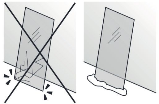
User manual

                                  EN

   Element sauna

Onni sauna (1-053-080)

                            1/8
                         11/2021”
Table of Contents
1. About this instruction manual            3

2. Product description                      4
  2.1.   Technical data                     4
  2.2.   Floor plan                         4
  2.3.   Scope of delivery                  5
  2.4.   Parts list                         6

3. Preparation for assembly                 7
  3.1. Tools required                       7
  3.2. Maintenance and cleaning             8
  3.3. Disposal                             8

4. Illustrations for assembling the cabin   9
Instructions for installation and use                                     p. 3/8

1. About this instruction manual
Read these installation and operating instructions carefully and keep them within
reach of the infrared cabin. This ensures that you can refer to information on
safety and operation at any time.

        These installation and operating instructions can also be found in
        the downloads section of our website: www.sentiotec.com/downloads.

Important note:
● Before you begin work, check the parts list to ensure that all the individual
  parts have been delivered. If you discover any missing parts, notify your
  dealer within 14 days of receiving the sauna cabin.
● The room that the sauna is installed in must be dry and ensure an appropriate
  amount of air circulation.
● The floor must be level and even, preferably a stone or tiled floor.
● A minimum room height of 230 cm is required for the cabin installation work.      EN
● A distance of at least 5 cm from the wall must be maintained.
● The inside of the wooden parts used must not be handled with any impreg-
  nating material.
● You need an assistant for the installation.
● Wood is a natural product that can swell, shrink or warp, despite good stor-
  age. For this reason, some force may be necessary during the installation.
All screw fittings must be pre-drilled.
Attention!
The electrical connection may only be performed by a qualified electrician
or similarly qualified person.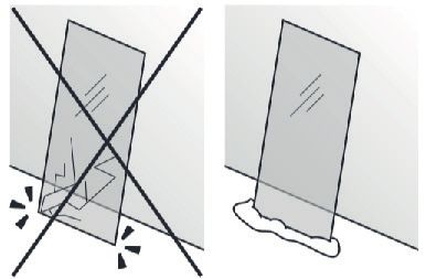
Instructions for installation and use                           p. 4/8

2. Product description
2.1. Technical data
Cabin material                          Abachi
Cabin dimensions (L x W (depth) x H)    1600 x 1600 x 2000 mm
Recommended heating output              7,5 – 9 kW

2.2. Floor plan
Instructions for installation and use   p. 5/8

2.3. Scope of delivery

                                                 EN
Instructions for installation and use p. 6/8
2.4. Parts list
No. NAME DIMENSIONS PIECES
1 Cover, roof element 1504 x 1504 x 5 mm 1
2 Roof element 1504 x 1504 x 63 mm 1
3 Rear wall 1507 x 2000 x 56 mm 1
4 Right side wall 1570 x 2000 x 46 mm 1
5 Left side wall 1570 x 2000 x 46 mm 1
6 Glass front 1600 x 2000 x 67 mm 1
7 Upper bench 1505 x 500 x 95 mm 2
8 Lower bench 1505 x 500 x 95 mm 1
9 Door handle 1960 x 80 x 32 mm 1
10 Floor grid 1505 x 650 x 60 mm 1
11 Heater protection grille 580 x 420 x 500 mm 1
12 Sauna lamp 1
13 Lamp protection grille 1
Installation material
Φ 4 x 35 Φ 4 x 45 Φ 4 x 35
12 pcs. 22 pcs. 6 pcs.Instructions for installation and use p. 7/8
3. Preparation for assembly
Before you begin work, check the parts list to ensure that all the individual parts
have been delivered. If you discover any missing parts, notify your dealer within
14 days of receiving the sauna cabin. Button
You need an assistant for assembly.
We also advise you to pre-drill the holes for the screws.
Check the right angle:
80 cm
60 cm
m
0c
10
EN
Handle glass with care: Special care must be taken with the edges of
the glass – hardened glass can shatter into small pieces in the event of
impact. Insert protective cushioning (e.g: cardboard box) under the edge
of the glass.
3.1. Tools required
Screwdriver Tape measure
Drill
Twist drill Utility knife
Spirit level Pencil Step ladderInstructions for installation and use p. 8/8
3.2. Maintenance and cleaning
● The sauna should be cleaned with a damp cloth. Only use warm water – no
cleaning products.
● We recommend heating the cabin once a month if the sauna is not used for
a long time.
3.3. Disposal
Dispose of packaging materials in accordance with the applicable
waste disposal regulations.
4. Illustrations for assembling the cabin
You will find the illustrations after the last languageBenutzerhandbuch
DE
Elementsauna
Onni Sauna (1-053-080)
1/8
11/2021Inhaltsverzeichnis 1. Zu dieser Anleitung 3 2. Produktbeschreibung 4 2.1. Technische Daten 4 2.2. Grundriss 4 2.3. Lieferumfang 5 2.4. Stückliste 6 3. Montagevorbereitung 7 3.1. Benötigtes Werkzeug 7 3.2. Wartung und Reinigung 8 3.3. Entsorgung 8 4. Montage Kabine Abbildungen 9
Montage- und Gebrauchsanweisung                                           S. 3/8

1. Zu dieser Anleitung
Lesen Sie diese Montage- und Gebrauchsanweisung gut durch und bewahren
Sie sie in der Nähe der Infrarotkabine auf. So können Sie jederzeit Informationen
zu Ihrer Sicherheit und zur Bedienung nachlesen.

       Sie finden diese Montage- und Gebrauchsanweisung auch im Download-
       bereich unserer Webseite auf www.sentiotec.com/downloads.
Wichtige Hinweise:
● Kontrollieren Sie, bevor Sie mit der Arbeit beginnen, anhand der Stückliste,
  ob alle Einzelteile auch tatsächlich mitgeliefert wurden. Sollten Einzelteile
  ausnahmsweise fehlen, benachrichtigen Sie spätestens 14 Tage nach Erhalt
  der Kabine Ihren Händler.
● Der Raum, in dem die Saunakabine montiert wird, muss trocken sein und             DE
  eine entsprechende Luftzirkulation gewährleisten.
● Der Fußboden muss waagrecht und eben sein, bevorzugt Stein- oder Flie-
  senboden.
● Für die Montagearbeiten der Kabine wird eine Mindestraumhöhe von 230 cm
  benötigt.
● Es muss ein Wandabstand von mindestens 5 cm eingehalten werden.
● Die Innen zu verwendenden Holzteile dürfen nicht mit Imprägniermittel be-
  handelt werden.
● Für die Montage benötigen Sie einen Helfer.
● Holz ist ein Naturprodukt, das trotz guter Lagerung aufquellen, schwinden
  oder sich verziehen kann. Aus diesem Grund kann es vorkommen, dass bei
  der Montage etwas Kraft aufgebracht werden muss.
Alle Verschraubungen müssen vorgebohrt werden.
Achtung!
Der Elektroanschluss darf nur durch eine Elektrofachkraft oder eine ver-
gleichsweise qualifizierte Person ausgeführt werden.
Montage- und Gebrauchsanweisung S. 4/8 2. Produktbeschreibung 2.1. Technische Daten Kabinenmaterial Abachi Kabinenmaße (L x B (Tiefe) x H) 1600 x 1600 x 2000 mm Empfohlene Ofenheizleistung 7,5 - 9 kW 2.2. Grundriss
Montage- und Gebrauchsanweisung   S. 5/8

2.3. Lieferumfang

                                           DE
Montage- und Gebrauchsanweisung S. 6/8
2.4. Stückliste
Nr. NAME ABMESSUNGEN STÜCK
1 Abdeckung Dachelement 1504 x 1504 x 5mm 1
2 Dachelement 1504 x 1504 x 63mm 1
3 Rückwand 1507 x 2000 x 56mm 1
4 Rechte Seitenwand 1570 x 2000 x 46mm 1
5 Linke Seitenwand 1570 x 2000 x 46mm 1
6 Glas Front 1600 x 2000 x 67mm 1
7 Obere Bank 1505 x 500 x 95mm 2
8 Untere Bank 1505 x 500 x 95mm 1
9 Türgriff 1960 x 80 x 32mm 1
10 Bodenrost 1505 x 650 x 60mm 1
11 Ofenschutzgitter 580 x 420 x 500mm 1
12 Saunaleuchte 1
13 Lampenschutzgitter 1
Montagematerial
Φ 4 x 35 Φ 4 x 45 Φ 4 x 35
12 Stk. 22 Stk. 6 Stk.Montage- und Gebrauchsanweisung S. 7/8
3. Montagevorbereitung
Kontrollieren Sie, bevor Sie mit der Arbeit beginnen, anhand der Stückliste, ob
alle Einzelteile auch tatsächlich mitgeliefert wurden. Sollten Einzelteile aus-
nahmsweise fehlen, benachrichtigen Sie spätestens 14 Tage nach Erhalt der
Kabine Ihren Händler. Taste
Für die Montage benötigen Sie einen Helfer!
Weiters empfehlen wir die Löcher für die Schrauben vorzubohren.
Überprüfung des rechten Winkel:
80 cm
60 cm
m
DE
0c
10
Vorsichtiger Umgang mit Glas: Besondere Vorsicht gilt den Glaskanten -
Gehärtetes Glas kann bei Stößen in kleine Scherben zerspringen. Legen
Sie ein Schutzpolster (z.Bsp.: Verpackungs-Karton) unter die Glaskante.
3.1. Benötigtes Werkzeug
Schraubendre-
Bandmaß
her (Kit) Bohrmaschine
Spiralbohrer
Cutter
(Kit)
Wasserwaage Bleistift StehleiterMontage- und Gebrauchsanweisung S. 8/8
3.2. Wartung und Reinigung
● Die Sauna sollte mit einem feuchten Tuch gereinigt werden. Verwenden Sie
nur warmes Wasser - keine Reinigungsmittel.
● Wird die Sauna längere Zeit nicht benutzt, empfehlen wir, die Kabine einmal
im Monat aufzuheizen.
3.3. Entsorgung
Entsorgen Sie die Verpackungsmaterialien nach den gültigen
Entsorgungsrichtlinien.
4. Montage Kabine Abbildungen
Die Abbildungen finden Sie nach der letzten Sprache.Manuel d’utilisateur
FR
Sauna à base d’éléments
Sauna Onni (1-053-080)
1/8
11/2021Table des matières 1. Concernant ces instructions 3 2. Description du produit 4 2.1. Caractéristiques techniques 4 2.2. Plan 4 2.3. Contenu de la livraison 5 2.4. Nomenclature 6 3. Préparation du montage 7 3.1. Outils requis 7 3.2. Entretien et nettoyage 8 3.3. Élimination 8 4. Illustrations de montage de la cabine 9
Instructions de montage et mode d’emploi                                  p. 3/8

1. Concernant ces instructions
Lisez attentivement ces instructions de montage et ce mode d’emploi et conser-
vez-les à proximité de la cabine infrarouge. Vous pouvez ainsi consulter à tout
moment des informations concernant son utilisation et relatives à votre sécurité.

       Ces instructions de montage et ce mode d’emploi sont également dis-
       ponibles dans la zone de téléchargement de notre site Internet
       www.sentiotec.com/downloads.

Remarques importantes :
● Avant de commencer les travaux, vérifiez au moyen de la nomenclature si
  toutes les pièces ont bien été livrées. S’il devait s’avérer que des pièces
  manquent, informez votre revendeur dans les 14 jours suivant la réception
  de la cabine.
● La pièce dans laquelle la cabine de sauna va être montée doit être sèche et
  disposer d’une circulation suffisante de l’air.
● Le sol doit être horizontal et lisse, de préférence en pierre ou carrelage.
                                                                                    FR
● Pour les travaux de montage de la cabine, la pièce doit faire au moins 230 cm
  de haut.
● Une distance d’au moins 5 cm avec le mur doit être respecté.
● Les pièces en bois prévues pour l’intérieur ne doivent pas être traitées avec
  un agent d’imprégnation.
● Une deuxième personne doit être disponible pour vous aider.
● Malgré un stockage correct, le bois est un produit naturel qui peut gonfler,
  se contracter ou se déformer. C’est pourquoi il peut arriver que vous ayez
  à appliquer de la force lors du montage.
Tous les raccords vissés doivent être préalésés.
Attention !
Seul un électricien spécialisé ou une personne ayant une qualification
similaire est habilité à procéder au raccordement électrique.
Instructions de montage et mode d’emploi p. 4/8 2. Description du produit 2.1. Caractéristiques techniques Matériau de la cabine Abachi Dimensions de la cabine (L x l (profondeur) x h) 1600 x 1600 x 2000 mm Puissance de chauffage recommandée 7,5 - 9 kW 2.2. Plan
Instructions de montage et mode d’emploi   p. 5/8

2.3. Contenu de la livraison

                                                    FR
Instructions de montage et mode d’emploi p. 6/8
2.4. Nomenclature
N° NOM DIMENSIONS PIÈCES
1 Cache d’élément de toit 1504 x 1504 x 5 mm 1
2 Élément de toit 1504 x 1504 x 63 mm 1
3 Paroi arrière 1507 x 2000 x 56 mm 1
4 Paroi latérale droite 1570 x 2000 x 46 mm 1
5 Paroi latérale gauche 1570 x 2000 x 46 mm 1
6 Façade vitrée 1600 x 2000 x 67 mm 1
7 Banc supérieur 1505 x 500 x 95 mm 2
8 Banc inférieur 1505 x 500 x 95 mm 1
9 Poignée de porte 1960 x 80 x 32 mm 1
10 Grille de plancher 1505 x 650 x 60 mm 1
11 Grilles de protection de poêle 580 x 420 x 500 mm 1
12 Éclairage de sauna 1
13 Grille de plancher
Matériel de montage
Φ 4 x 35 Φ 4 x 45 Φ 4 x 35
12 22 6Instructions de montage et mode d’emploi p. 7/8
3. Préparation du montage
Avant de commencer les travaux, vérifiez au moyen de la nomenclature si toutes
les pièces ont bien été livrées. S’il devait s’avérer que des pièces manquent, infor-
mez votre revendeur dans les 14 jours suivant la réception de la cabine. Touche
Une deuxième personne doit être disponible pour vous aider.
En outre, nous recommandons de prépercer les trous pour les vis.
Contrôle de l’angle droit :
80 cm
60 cm
m
0c
10
FR
Manipulez le verre avec soin : Faire particulièrement attention avec les
bords de la vitre ; en cas de choc, le verre trempé peut se briser en petits
morceaux. Placez un rembourrage de protection (par ex., un emballage
en carton) sous le bord de la vitre.
3.1. Outils requis
Tournevis Mètre ruban
Perceuse
Foret hélicoïdal Cutter
Niveau à bulle Crayon à papier EscabeauInstructions de montage et mode d’emploi p. 8/8
3.2. Entretien et nettoyage
● Le sauna doit être nettoyé au moyen d’un chiffon humide. N’utilisez que de
l’eau chaude, pas de détergent.
● Si le sauna n’est pas utilisé pendant une période prolongée, nous recom-
mandons de chauffer la cabine une fois par mois.
3.3. Élimination
Éliminez les matériaux d’emballage conformément aux directives en
vigueur relatives à l’élimination.
4. Illustrations de montage de la cabine
Les illustrations se trouvent après les dernières languesManuale d’uso
IT
Sauna a elementi
Onni Sauna (1-053-080)
1/8
11/2021Indice 1. Informazioni sul presente manuale 3 2. Descrizione del prodotto 4 2.1. Specifiche tecniche 4 2.2. Pianta 4 2.3. Dotazione 5 2.4. Elenco dei pezzi 6 3. Preparazione per il montaggio 7 3.1. Attrezzi necessari 7 3.2. Manutenzione e pulizia 8 3.3. Smaltimento 8 4. Figure di montaggio cabina 9
Istruzioni di montaggio e per l’uso                                               P. 3/8

1. Informazioni sul presente manuale
Leggere attentamente le presenti istruzioni di montaggio e d’uso e conservarle
vicino alla cabina a infrarossi. Così facendo è possibile controllare in ogni mo-
mento le informazioni sulla sicurezza e sull’utilizzo.

        Le presenti istruzioni di montaggio e d’uso si trovano anche
        nell’area di download della nostra pagina web all’indirizzo:
        www.sentiotec.com/downloads.

Indicazioni importanti:
● Prima di iniziare i lavori, controllare in base all’elenco dei pezzi se tutti i singoli
   componenti sono stati effettivamente forniti. Se eccezionalmente dovessero
   mancare dei singoli componenti, contattare il proprio fornitore entro 14 giorni
   dal ricevimento della cabina.
● L’ambiente in cui la cabina della sauna viene montata deve essere asciutto
   e garantire la circolazione dell’aria richiesta.
● Il pavimento deve essere orizzontale e uniforme, preferibilmente in pietra
   o piastrelle.
● Per i lavori di montaggio della cabina è necessaria un’altezza minima libera
   di 230 cm.
                                                                                            IT
● Mantenere una distanza minima dalle pareti di 5 cm.
● I componenti in legno da utilizzare all’interno non devono essere trattati con
   impregnante.
● Per il montaggio è richiesto l’aiuto di una seconda persona.
● Il legno è un prodotto naturale che può gonfiarsi, ritirarsi o deformarsi anche
   se immagazzinato correttamente. In fase di montaggio potrebbe quindi essere
   necessario applicare una certa forza.
Tutte le connessioni a vite devono essere preforate.
Attenzione!
Il collegamento elettrico deve essere eseguito da elettricisti specializzati
o da persone con una qualifica simile.
Istruzioni di montaggio e per l’uso P. 4/8 2. Descrizione del prodotto 2.1. Specifiche tecniche Materiale della cabina Obeche Dimensioni cabina (L x L (profondità) x A) 1600 x 1600 x 2000 mm Potenza di riscaldamento stufa consigliata 7,5 - 9 kW 2.2. Pianta
Istruzioni di montaggio e per l’uso   P. 5/8

2.3. Dotazione

                                               IT
Istruzioni di montaggio e per l’uso P. 6/8
2.4. Elenco dei pezzi
N. NOME DIMENSIONI PEZZI
1 Copertura elemento tetto 1504 x 1504 x 5 mm 1
2 Elemento tetto 1504 x 1504 x 63 mm 1
3 Pannello posteriore 1507 x 2000 x 56 mm 1
4 Pannello laterale destro 1570 x 2000 x 46 mm 1
5 Pannello laterale sinistro 1570 x 2000 x 46 mm 1
6 Vetro anteriore 1600 x 2000 x 67 mm 1
7 Panca superiore 1505 x 500 x 95 mm 2
8 Panca inferiore 1505 x 500 x 95 mm 1
9 Maniglia porta 1960 x 80 x 32 mm 1
10 Griglia di fondo 1505 x 650 x 60 mm 1
11 Griglia di protezione stufa 580 x 420 x 500 mm 1
12 Lampada 1
13 Griglia di fondo 1
Materiale di montaggio
Φ 4 x 35 Φ 4 x 45 Φ 4 x 35
12 pz. 22 pz. 6 pz.Istruzioni di montaggio e per l’uso P. 7/8
3. Preparazione per il montaggio
Prima di iniziare i lavori, controllare in base all’elenco dei pezzi se tutti i singoli
componenti sono stati effettivamente forniti. Se eccezionalmente dovessero
mancare dei singoli componenti, contattare il proprio fornitore entro 14 giorni
dal ricevimento della cabina. Tasto
Per il montaggio è richiesto l’aiuto di una seconda persona.
Raccomandiamo anche di preforare i fori per le viti.
Verifica dell’ortogonalità:
80 cm
60 cm
m
0c
10
Maneggiare il vetro con cura: particolare attenzione deve essere prestata IT
ai bordi del vetro - il vetro temprato può frantumarsi in piccoli pezzi in caso
di impatto. Inserire un cuscino di protezione (ad es: scatola di cartone)
sotto il bordo del vetro.
3.1. Attrezzi necessari
Cacciavite Metro a nastro
Trapano
Trapano a punta
Taglierina
elicoidale
Livella a bolla Matita Scala a libroIstruzioni di montaggio e per l’uso P. 8/8
3.2. Manutenzione e pulizia
● La sauna deve essere pulita con un panno umido. Utilizzare solo acqua calda
senza detergenti.
● Se la sauna non viene utilizzata per un tempo prolungato, si consiglia di
riscaldare la cabina una volta al mese.
3.3. Smaltimento
Smaltire i materiali dell’imballaggio conformemente alle normative
sullo smaltimento vigenti.
4. Figure di montaggio cabina
Le figure sono riportate dopo l’ultima linguaGebruikershandboek
NL
Elementsauna
Onni Sauna (1-053-080)
1/8
11/2021Inhoudsopgave 1. Over deze handleiding 3 2. Productbeschrijving 4 2.1. Technische gegevens 4 2.2. Plattegrond 4 2.3. Leveromvang 5 2.4. Stuklijst 6 3. Montagevoorbereiding 7 3.1. Vereist gereedschap 7 3.2. Onderhoud en reiniging 8 3.3. Afvoer 8 4. Montage cabine afbeeldingen 8
Montage- en gebruiksaanwijzing                                            Pag. 3/8

1. Over deze handleiding
Lees deze montage- en gebruiksaanwijzing goed door en bewaar deze in de
buurt van de infraroodcabine. Zo kunt u te allen tijde informatie over uw veiligheid
en de bediening nalezen.

        U vindt deze montage- en gebruiksaanwijzing ook op onze website:
        www.sentiotec.com/downloads.

Belangrijke aanwijzingen:
● Controleer alvorens met de montage te beginnen aan de hand van de stuklijst
  of alle afzonderlijke delen werden geleverd. Als er delen ontbreken, neem dan
   uiterlijk 14 dagen na ontvangst van de cabine contact op met uw handelaar.
● De ruimte waarin de saunacabine wordt gemonteerd, moet droog zijn en er
  moet een goede luchtcirculatie gegarandeerd zijn.
● De vloer moet waterpas en effen zijn, bij voorkeur een stenen vloer of tegelvloer.
● Voor de montagewerkzaamheden van de cabine is een minimale ruimtehoogte
  van 230 cm vereist.
● De afstand tot de wand moet minstens 5 cm bedragen.
● De houten onderdelen die binnenin worden gebruikt, mogen niet worden
  behandeld met impregneermiddel.
● De montage moet door twee personen worden uitgevoerd.
● Hout is een natuurlijk product dat ondanks correcte opslag kan uitzetten,
  krimpen of krom trekken. Daardoor kan het zijn dat bij de montage kracht             NL
  moet worden toegepast.
Alle schroefverbindingen moeten worden voorgeboord.
Let op!
De elektrische aansluiting mag alleen worden uitgevoerd door een elektri-
cien of een vergelijkbaar gekwalificeerd persoon.
Montage- en gebruiksaanwijzing Pag. 4/8 2. Productbeschrijving 2.1. Technische gegevens Cabinemateriaal Abachi Afmetingen cabine (l x b (diepte) x h) 1600 x 1600 x 2000 mm Aanbevolen kachelvermogen 7,5 - 9 kW 2.2. Plattegrond
Montage- en gebruiksaanwijzing   Pag. 5/8

2.3. Leveromvang

                                            NL
Montage- en gebruiksaanwijzing Pag. 6/8
2.4. Stuklijst
Nr. NAAM AFMETINGEN STUKS
1 Afdekking dakelement 1504 x 1504 x 5 mm 1
2 Dakelement 1504 x 1504 x 63 mm 1
3 Achterwand 1507 x 2000 x 56 mm 1
4 Rechter zijwand 1570 x 2000 x 46 mm 1
5 Linker zijwand 1570 x 2000 x 46 mm 1
6 Glazen front 1600 x 2000 x 67 mm 1
7 Bovenste bank 1505 x 500 x 95 mm 2
8 Onderste bank 1505 x 500 x 95 mm 1
9 Deurgreep 1960 x 80 x 32 mm 1
10 Vloerrooster 1505 x 650 x 60 mm 1
11 Kachelbeschermingsrooster 580 x 420 x 500 mm 1
12 Saunalicht 1
13 Lampbeschermingsmateriaal 1
Montagemateriaal
Φ 4 x 35 Φ 4 x 45 Φ 4 x 35
12 stk. 22 stk. 6 stk.Montage- en gebruiksaanwijzing Pag. 7/8
3. Montagevoorbereiding
Controleer alvorens met de montage te beginnen aan de hand van de stuklijst
of alle afzonderlijke delen werden geleverd. Als er delen ontbreken, neem dan
uiterlijk 14 dagen na ontvangst van de cabine contact op met uw handelaar.
Voor de montage heeft u een tweede persoon nodig!
Bovendien raden we aan om de gaten voor de schroeven voor te boren.
Controle van de rechte hoek:
Voorzichtige omgang met glas: met de glazen randen dient u bijzonder
voorzichtig om te gaan – gehard glas kan door stoten in kleine scherven
versplinteren. Leg een beschermende ondergrond (bijv.: verpakkingskar-
ton) onder de glazen rand. NL
3.1. Vereist gereedschap
Schroeven-
Bandmaat
draaier (kit) Boormachine
Spiraalboor
Cutter
(kit)
Waterpas Potlood Staande ladderMontage- en gebruiksaanwijzing Pag. 8/8
3.2. Onderhoud en reiniging
● De sauna moet met een vochtige doek worden gereinigd. Gebruik alleen
warm water, geen reinigingsmiddel.
● Als de sauna voor langere tijd niet wordt gebruikt, adviseren wij de cabine
een keer per maand te verwarmen.
3.3. Afvoer
Voer het verpakkingsmateriaal af volgens de geldende afvoerrichtlijnen.
4. Montage cabine afbeeldingen
De afbeeldingen vindt u na de laatste taal.Pictures p. 9/11
4.
1 2
3 4 8Pcs
4 x 45Pictures p. 10/11
5 6Pcs 6
4 x 35
7 9 6Pcs
4 x 45
8 6Pcs
4 x 45Pictures p. 11/11
a b
c 2Pcs
2Pcs d 4Pcs
4 x 45 4 x 35
4 x 35Onni Sauna 1. 2. Version 02/22 1-053-080
Onni Sauna
3.

4.

     9 Pcs

     4 x 70

        sentiotec GmbH | Division of Harvia Group | Wartenburger Straße 31, A-4840 Vöcklabruck
              T +43 (0) 7672/22 900-50 | F -80 | info@sentiotec.com | www.sentiotec.com
Sie können auch lesen