MONTAGEANLEITUNG INSTALLATION GUIDE - tempLED RayField V2
←
→
Transkription von Seiteninhalten
Wenn Ihr Browser die Seite nicht korrekt rendert, bitte, lesen Sie den Inhalt der Seite unten
MONTAGEANLEITUNG
INSTALLATION GUIDE

tempLED RayField V2

                     tempLED GmbH
                       V.01/2021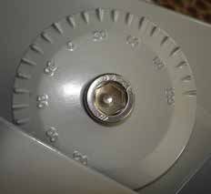
MONTAGEANLEITUNG                                                           INSTALLATION GUIDE

tempLED RayField V2 Serie                                                  tempLED RayField V2 series
Allgemeine Sicherheitshinweise                                             General safety notes
                                                             1
Vorsicht!                                                                  Caution!
Gefahr eines elektrischen Schlages!                                        Risk of electric shock!

Montage und Inbetriebnahme der Leuchte nur                                 Mounting and installation of the luminaire only
durch autorisierte Fachkräfte. Vor jeder Arbeit                            by authorized personnel. Disconnect the power
an der Leuchte die Stromzufuhr unterbrechen                                supply and protect it from restarting by mistake
und gegen versehentliches Wiedereinschalten                                before working on the luminaire. The lumin-
sichern. Die Leuchte darf nur mit vollständigem                            aire must only be operated with complete and
und unbeschädigtem Gehäuse in Betrieb genom-                               undamaged housing. Please secure the main
men werden. Die Stromzufuhr ist mit geeigneten                             power by means of suitable measures, for ex-
Maßnahmen (Fehlerstrom-Schutzschalter o.ä.)                                ample a residual current circuit breaker.
abzusichern.

                                                             2
Vorsicht!                                                                  Caution!
Absturzgefahr!                                                             Danger of falling!

Bei der Montage der Leuchte ist darauf zu                                  Please use suitable mounting material (screws,
achten, dass das gewählte Montagematerial                                  wall plugs) and dimensions for the drilling holes
(Schrauben, Dübel) sowie die Dimensionen von                               and screws. They must be suitable for the weight
Bohrlöchern und Schrauben für das Gewicht der                              of the luminaire as well as the composition and
Leuchte und die Beschaffenheit und Tragfähig-                              bearing capacity of the mounting location. No
keit der Montageoberfläche geeignet ist.                                   liability for damages resulting from improper
Keine Haftung für fehlerhaft ausgeführte Monta-                            installation, inexpert operation or modification of
ge, unsachgemäßen Betrieb oder Veränderun-                                 the luminaire!
gen an der Leuchte!

                                                             3
Lieferumfang:                                                                        Package contents:

- Leuchte der RayField V2-Serie mit                                                  - RayField V2 luminaire with
  vormontiertem Haltebügel und Stütz-                                                  pre-assembled holder and supporting
  streben                                                                              struts

                          © tempLED GmbH | Marmorwerkstraße 52 | 83088 Kiefersfelden | Deutschland
                              info@tempLED.de | www.tempLED.de | WEEE-Reg.-Nr.: DE 26163456

                                                         V.01/2021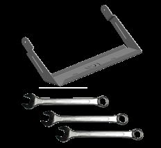
MONTAGEANLEITUNG                                                                                                         INSTALLATION GUIDE

tempLED RayField V2 Serie                                                                                                tempLED RayField V2 series
Wandmontage                                                                                                              Wall installation
                                                                          1
Schritt 1:                                                                                                               Step 1:
Wichtiger Hinweis!                                                                                                       Important Note!
                                                                         kg

Aufgrund des Produktgewichtes emp-                                                                                       Due to the weight of the luminaire start-
fehlen wir die Montage der Leuchte ab                                                                                    ing at RayField V2 800, we recommend
der Version RayField V2 800 mit zwei                                                                                     to conduct all works with two people.
Personen.

                                                                          2
Schritt 2:                                                                                                               Step 2:
Abnehmen des Montagebügels                                                                                               Removing the mounting bracket

Nehmen Sie den Montagebügel [1] und                                                                                      Remove the mounting bracket [1] and
die Stützstreben [2] von der Leuchte                                                                                     the support struts [2] from the lumin-
ab. Dazu benötigen Sie einen Inbus-            1                                                                         aire. You need an Allen key size 5 (sup-
schlüssel der Größe 5 (Stützstrebe)                                                                                      port struts) and 12 (mounting bracket)
und der Größe 12 (Montagebügel).                                                                                         or a hex wrench size 5 (support struts)
                                                                                                                         and 12 (mounting bracket).
                                                                                               2
Achten Sie darauf, dass Abstandshal-
ter, Beilagscheiben und Muttern nicht                                                                                    Be careful not to lose the spacers,
verloren gehen.                                                                                                          washers and nuts.

                                                                          3
Schritt 3:                                                                                                               Step 3:
Anzeichnen der Bohrlöcher 1                                                                                              Marking the drill holes 1

Zeichnen Sie die Bohrlöcher an der                                   140,00 mm
                                                                                                                         Mark the drill holes on the surface of
Oberfläche des Montageortes an.                                                                                          the mounting location. Please use the
                                                         70,00 mm                70,00 mm
                                                                                                              63,00 mm

Nehmen Sie dazu die nebenstehen-                                                                                         measurement drawing on the left for
                                                                                    15,00 mm
                                                         46,00 mm

de Masszeichnung zur Montage der                                                                                         mounting the RayField V2 400 and
RayField V2 400 und RayField V2 500           62,00 mm               15,00 mm                      62,00 mm              RayField V2 500 luminaire.
zur Hilfe.                                                           355,00 mm

                          © tempLED GmbH | Marmorwerkstraße 52 | 83088 Kiefersfelden | Deutschland
                              info@tempLED.de | www.tempLED.de | WEEE-Reg.-Nr.: DE 26163456

                                                                    V.01/2021
MONTAGEANLEITUNG INSTALLATION GUIDE
tempLED RayField V2 Serie tempLED RayField V2 series
Wandmontage Wall installation
4
Schritt 4: Step 4:
Anzeichnen der Bohrlöcher 2 Marking the drill holes 2
Zeichnen Sie die Bohrlöcher an der 300,00 mm
Mark the drill holes on the surface of
Oberfläche des Montageortes an. Neh- the mounting location. Please use the
150,00 mm 150,00 mm
men Sie dazu die nebenstehende Mas- measurement drawing on the left for
65,00 mm
15,00 mm
45,00 mm
szeichnung zur Montage der RayField mounting the RayField V2 800 and
V2 800 und RayField V2 1000 zur Hilfe. 85,00 mm 15,00 mm 85,00 mm RayField V2 1000 luminaire.
615,00 mm
5
Schritt 5: Step 5:
Anzeichnen der Bohrlöcher 3 Marking the drill holes 3
Zeichnen Sie die Bohrlöcher an der 400,00 mm
Mark the drill holes on the surface of
Oberfläche des Montageortes an. 200,00 mm 200,00 mm
the mounting location. Please use the
Nehmen Sie dazu die nebenstehende measurement drawing on the left for
68,00 mm
15,00 mm
42,00 mm
Masszeichnung zur Montage der Ray- mounting the RayField V2 1200 and
Field V2 1200 und RayField V2 1500 100,00 mm 15,00 mm 100,00 mm RayField V2 1500 luminaire.
zur Hilfe.
870,00 mm
6
Schritt 6: Step 6:
Bohrlöcher anfertigen Drilling the holes
Prüfen Sie ggf. die Stellen der Bohrlö- Please check the drilling spots with a
cher mit einem Leitungssuchgerät und line locator and drill the holes. Choose
fertigen Sie dann die Bohrlöcher an. a drill hole diameter suitable for the
Wählen Sie einen der Montageober- material of the mounting surface and
fläche und dem Gewicht der Leuchte the weight of the luminaire.
angepassten Bohrlochdurchmesser. (symbol illustration)
(Symbolabbildung) Leit
un
ON
F
/O
F
g
Lin ssuc
e lo hg
cat erät
or
Driller icon made by Freepik from www.flaticon.com
© tempLED GmbH | Marmorwerkstraße 52 | 83088 Kiefersfelden | Deutschland
info@tempLED.de | www.tempLED.de | WEEE-Reg.-Nr.: DE 26163456
V.01/2021MONTAGEANLEITUNG INSTALLATION GUIDE
tempLED RayField V2 Serie tempLED RayField V2 series
Wandmontage Wall installation
7
Schritt 7: Step 7:
Montieren des Bügels Mounting the mounting bracket
Montieren Sie den Haltebügel mit Screw the mounting bracket to the
geeignetem Schraubenmaterial für die surface. Use screw material suitable for
Montageoberfläche und dem Gewicht the mounting surface and the weight
der Leuchte. Wir empfehlen den Ein- of the luminaire. We recommend
satz von Edelstahlschrauben. high-grade steel screws and mounting
(Symbolabbildung) material.
(symbol illustration)
8
Schritt 8: Step 8:
Montieren der Leuchte 1 Mounting the luminaire 1
Montieren Sie die Leuchte mit dem Mount the luminaire on the mounting
Kabelauslass nach unten an den Mon- bracket with the cable output facing
tagebügel und ziehen die Halteschrau- down and tighten the holder screws
ben leicht mit einem Inbusschlüssel der lightly by using an Allen key size 12 or
Größe 12 an. a hex wrench size 12.
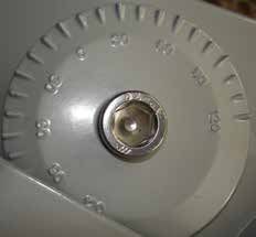
Richten Sie die Leuchte nach Ihren Adjust the luminaire according to your
Wünschen anhand der Rasterverstel- specific needs by using the incremental
lung aus und ziehen Sie die Halte- adjustment scale.
schrauben fest. Finally tight the holding screws.
9
Schritt 9: Step 9:
Montieren der Leuchte 2 Mounting the luminaire 2
Montieren Sie anschließen die beiden Mount the two support struts onto
Stützstreben an die Oberseite der the top of the luminaire as shown on
Leuchte wie auf der Abbildung rechts the picture to the left and tighten the
und ziehen die Schrauben mit einem screws by using an Allen key size 5 or
Inbusschlüssel der Größe 5 an. a hex wrench size 5.
Vergessen Sie die Abstandshalter, Do not forget the spacers, washers and
Beilagscheiben und Muttern nicht. nuts.
Wir empfehlen ein Drehmoment von We recommend a maximum torque of
maximal 7,5 Nm für alle Schrauben. 7.5 Nm for all screws.
© tempLED GmbH | Marmorwerkstraße 52 | 83088 Kiefersfelden | Deutschland
info@tempLED.de | www.tempLED.de | WEEE-Reg.-Nr.: DE 26163456
V.01/2021MONTAGEANLEITUNG INSTALLATION GUIDE
tempLED RayField V2 Serie tempLED RayField V2 series
Deckenmontage Ceiling installation
1
Schritt 1: Step 1:
Wichtiger Hinweis! Important Note!
kg
Aufgrund des Produktgewichtes emp- Due to the weight of the luminaire start-
fehlen wir die Montage der Leuchte ab ing at RayField V2 800, we recommend
der Version RayField V2 800 mit zwei to conduct all works with two people.
Personen.
2
Schritt 2: Step 2:
Abnehmen des Montagebügels Removing the mounting bracket
Nehmen Sie den Montagebügel [1] und Remove the mounting bracket [1] and
die Stützstreben [2] von der Leuchte the support struts [2] from the lumin-
ab. Dazu benötigen Sie einen Inbus- 1 aire. You need an Allen key size 5 (sup-
schlüssel der Größe 5 (Stützstrebe) port struts) and 12 (mounting bracket)
und der Größe 12 (Montagebügel). or a hex wrench size 5 (support struts)
and 12 (mounting bracket).
2
Die Stützstreben werden bei der
Deckenmontage nicht benötigt und You do not need the support struts any
können komplett abmontiert werden. longer so you can put them aside.
3
Schritt 3: Step 3:
Anzeichnen der Bohrlöcher 1 Marking the drill holes 1
Zeichnen Sie die Bohrlöcher an der 140,00 mm
Mark the drill holes on the surface of
Oberfläche des Montageortes an. the mounting location. Please use the
70,00 mm 70,00 mm
63,00 mm
Nehmen Sie dazu die nebenstehen- measurement drawing on the left for
15,00 mm
46,00 mm
de Masszeichnung zur Montage der mounting the RayField V2 400 and
RayField V2 400 und RayField V2 500 62,00 mm 15,00 mm 62,00 mm RayField V2 500 luminaire.
zur Hilfe. 355,00 mm
© tempLED GmbH | Marmorwerkstraße 52 | 83088 Kiefersfelden | Deutschland
info@tempLED.de | www.tempLED.de | WEEE-Reg.-Nr.: DE 26163456
V.01/2021MONTAGEANLEITUNG INSTALLATION GUIDE
tempLED RayField V2 Serie tempLED RayField V2 series
Deckenmontage Ceiling installation
4
Schritt 4: Step 4:
Anzeichnen der Bohrlöcher 2 Marking the drill holes 2
Zeichnen Sie die Bohrlöcher an der 300,00 mm
Mark the drill holes on the surface of
Oberfläche des Montageortes an. Neh- the mounting location. Please use the
150,00 mm 150,00 mm
men Sie dazu die nebenstehende Mas- measurement drawing on the left for
65,00 mm
15,00 mm
45,00 mm
szeichnung zur Montage der RayField mounting the RayField V2 800 and
V2 800 und RayField V2 1000 zur Hilfe. 85,00 mm 15,00 mm 85,00 mm RayField V2 1000 luminaire.
615,00 mm
5
Schritt 5: Step 5:
Anzeichnen der Bohrlöcher 3 Marking the drill holes 3
Zeichnen Sie die Bohrlöcher an der 400,00 mm
Mark the drill holes on the surface of
Oberfläche des Montageortes an. 200,00 mm 200,00 mm
the mounting location. Please use the
Nehmen Sie dazu die nebenstehende measurement drawing on the left for
68,00 mm
15,00 mm
42,00 mm
Masszeichnung zur Montage der Ray- mounting the RayField V2 1200 and
Field V2 1200 und RayField V2 1500 100,00 mm 15,00 mm 100,00 mm RayField V2 1500 luminaire.
zur Hilfe.
870,00 mm
6
Schritt 6: Step 6:
Bohrlöcher anfertigen Drilling the holes
Prüfen Sie ggf. die Stellen der Bohrlö- Please check the drilling spots with a
cher mit einem Leitungssuchgerät und line locator and drill the holes. Choose
fertigen Sie dann die Bohrlöcher an. a drill hole diameter suitable for the
Wählen Sie einen der Montageober- material of the mounting surface and
fläche und dem Gewicht der Leuchte the weight of the luminaire.
angepassten Bohrlochdurchmesser. (symbol illustration)
(Symbolabbildung) Leit
un
ON
F
/O
F
g
Lin ssuc
e lo hg
cat erät
or
Driller icon made by Freepik from www.flaticon.com
© tempLED GmbH | Marmorwerkstraße 52 | 83088 Kiefersfelden | Deutschland
info@tempLED.de | www.tempLED.de | WEEE-Reg.-Nr.: DE 26163456
V.01/2021MONTAGEANLEITUNG INSTALLATION GUIDE
tempLED RayField V2 Serie tempLED RayField V2 series
Deckenmontage Ceiling installation
7
Schritt 7: Step 7:
Montieren des Bügels Mounting the mounting bracket
Montieren Sie den Haltebügel mit Screw the mounting bracket to the
geeignetem Schraubenmaterial für die surface. Use screw material suitable for
Montageoberfläche und dem Gewicht the mounting surface and the weight
der Leuchte. Wir empfehlen den Ein- of the luminaire. We recommend
satz von Edelstahlschrauben. high-grade steel screws and mounting
(Symbolabbildung) material.
(symbol illustration)
8
Schritt 8: Step 8:
Montieren der Leuchte 1 Mounting the luminaire 1
Montieren Sie die Leuchte an den Mon- Mount the luminaire on the mounting
tagebügel und ziehen die Halteschrau- bracket and tighten the holder screws
ben leicht mit einem Inbusschlüssel der lightly by using an Allen key size 12 or
Größe 12 an. a hex wrench size 12.
Richten Sie die Leuchte waagrecht Adjust the luminaire horizontally by
anhand der Rasterverstellung aus und using the incremental adjustment scale.
ziehen Sie die Halteschrauben fest. Finally tight the holding screws.
9
Schritt 9: Step 9:
Montieren der Leuchte 2 Mounting the luminaire 2
Richten Sie die Leuchte waagrecht Adjust the luminaire horizontally by
anhand der Rasterverstellung aus und using the incremental adjustment scale.
ziehen Sie die Halteschrauben fest. Finally tight the holding screws.
Wir empfehlen ein Drehmoment von We recommend a maximum torque of
maximal 7,5 Nm für alle Schrauben. 7.5 Nm for all screws.
© tempLED GmbH | Marmorwerkstraße 52 | 83088 Kiefersfelden | Deutschland
info@tempLED.de | www.tempLED.de | WEEE-Reg.-Nr.: DE 26163456
V.01/2021MONTAGEANLEITUNG INSTALLATION GUIDE
tempLED RayField V2 Serie tempLED RayField V2 series
Traversenmontage Truss installation
1
Schritt 1: Step 1:
Wichtiger Hinweis! Important Note!
kg
Aufgrund des Produktgewichtes emp- Due to the weight of the luminaire start-
fehlen wir die Montage der Leuchte ab ing at RayField V2 800, we recommend
der Version RayField V2 800 mit zwei to conduct all works with two people.
Personen.
2
Schritt 2: Step 2:
Abnehmen des Montagebügels Removing the mounting bracket
Nehmen Sie den Montagebügel [1] und Remove the mounting bracket [1] and
die Stützstreben [2] von der Leuchte the support struts [2] from the lumin-
ab. Dazu benötigen Sie einen Inbus- 1 aire. You need an Allen key size 5 (sup-
schlüssel der Größe 5 (Stützstrebe) port struts) and 12 (mounting bracket)
und der Größe 12 (Montagebügel). or a hex wrench size 5 (support struts)
and 12 (mounting bracket).
2
Achten Sie darauf, dass Abstandshal-
ter, Beilagscheiben und Muttern nicht Be careful not to lose the spacers,
verloren gehen. washers and nuts.
3
Schritt 3: Step 3:
Montieren des Traversenbügels Mounting the truss bracket
Montieren Sie den Traversenbügel Screw the the truss bracket (accesso-
(Zubehör) mit geeignetem Schrauben- ry) to the surface. Use screw material
material für die Montageoberfläche suitable for the mounting surface and
und dem Gewicht der Leuchte. Wir the weight of the luminaire. We rec-
empfehlen den Einsatz von Edelstahl- ommend high-grade steel screws and
schrauben. mounting material.
(Symbolabbildung) (symbol illustration)
© tempLED GmbH | Marmorwerkstraße 52 | 83088 Kiefersfelden | Deutschland
info@tempLED.de | www.tempLED.de | WEEE-Reg.-Nr.: DE 26163456
V.01/2021MONTAGEANLEITUNG INSTALLATION GUIDE
tempLED RayField V2 Serie tempLED RayField V2 series
Traversenmontage Truss installation
4
Schritt 4: Step 4:
Detailabmessungen 1 Detail dimensions 1
Die Abbildung auf der rechten Seite The illustration on the left shows the
⌀
zeigt die seitlichen Detailabmessungen
⌀ detailed lateral dimensions of the truss
°
des Traversenbügels. bracket.
Diese Detailabmessungen gelten für These detailed dimensions apply to all
alle Traversenbügel. truss brackets.
⌀
⌀
°
∠ ↑ °
∠ ↑ ° ∠ ↑
∠ ↓ ° ∠
5 ∠↑
Schritt 5: Ø Step 5: ∠↓
Detailabmessungen 2 Detail dimensions 2
Ø
Die Abbildung auf der rechten Seite The illustration on the left shows the
Ø
zeigt die Detailabmessungen des Dreh- detailed
⌀ dimensions of the slewing ring
kranzes des Traversenbügels. of the truss bracket.
Diese Detailabmessungen gelten für ⌀
These detailed dimensions apply to all
alle Traversenbügel. truss brackets.
⌀
⌀
⌀
°
6
Schritt 6: Step 6: ∠ ↑ °
Anzeichnen der Bohrlöcher 1 Marking the drill holes 1
∠ ↓ °
Zeichnen Sie die Bohrlöcher an der Mark the drill holes on the surface of
Oberfläche des Montageortes an. the mounting location. Please use the
Nehmen Sie dazu die nebenstehen- ⌀ measurement drawing on the left for
de Masszeichnung zur Montage der mounting the RayField V2 400 and
⌀
RayField V2 400 und RayField V2 500 RayField V2 500 luminaire.
zur Hilfe. ⌀
© tempLED GmbH | Marmorwerkstraße 52 | 83088 Kiefersfelden | Deutschland
info@tempLED.de | www.tempLED.de | WEEE-Reg.-Nr.: DE 26163456
V.01/2021MONTAGEANLEITUNG INSTALLATION GUIDE
tempLED RayField V2 Serie ⌀
tempLED RayField V2 series
⌀
Traversenmontage Truss installation
°
7
Schritt 7: Step 7: ∠ ↑ °
∠ ↑ °
Anzeichnen der Bohrlöcher 2 Marking the drill
∠ ↓ holes
° 2 ∠ ↑ ° ∠ ↑
∠
Zeichnen Sie die Bohrlöcher an der Mark the drill holes on the surface of
Oberfläche des Montageortes an. Neh- the mounting location. Please use∠ the
↑ °
⌀
men Sie dazu die nebenstehende Mas- measurement drawing on the left for
⌀
szeichnung zur Montage der RayField mounting the RayField V2 800 and
⌀
V2 800 und RayField V2 1000 zur Hilfe. RayField V2 1000 luminaire.
⌀
⌀
°
°
8
Schritt 8: Step 8:
Anzeichnen der Bohrlöcher 3 Marking the drill holes 3 ∠ ↑ °
∠ ↑ ° ∠ ↑ ° ∠ ↑
∠ ↓ °
∠ ↑
Zeichnen Sie die Bohrlöcher an der Mark the drill holes on the surface of ∠
Oberfläche des Montageortes an. the mounting location. Please use the
Nehmen Sie dazu die nebenstehende ⌀ measurement drawing on the left for ∠ ↑ °
Masszeichnung zur Montage der Ray- ⌀
⌀
mounting the RayField V2 1200 and
Field V2 1200 und RayField V2 1500 RayField V2 1500 luminaire.
zur Hilfe.
°
9
Schritt 9: Step 9:
Montieren der Leuchte 1 Mounting the luminaire 1
Montieren Sie die Leuchte mit dem Ka- Mount the luminaire on the truss brack-
belauslass nach unten an den Traver- et with the cable output facing down
senbügel und ziehen die Halteschrau- and tighten the holder screws lightly
ben leicht mit einem Inbusschlüssel der by using an Allen key size 12 or a hex
Größe 12 an. wrench size 12.
Richten Sie die Leuchte nach Ihren Adjust the luminaire according to your
Wünschen anhand der Rasterverstel- specific needs by using the incremental
lung aus und ziehen Sie die Halte- adjustment scale.
schrauben fest. Finally tight the holding screws.
© tempLED GmbH | Marmorwerkstraße 52 | 83088 Kiefersfelden | Deutschland
info@tempLED.de | www.tempLED.de | WEEE-Reg.-Nr.: DE 26163456
V.01/2021MONTAGEANLEITUNG INSTALLATION GUIDE
tempLED RayField V2 Serie tempLED RayField V2 series
Traversenmontage Truss installation
10
Schritt 10: Step 10:
Montieren der Leuchte 2 Mounting the luminaire 2
Montieren Sie anschließen die beiden Mount the two support struts onto the
Stützstreben am Traversenbügel wie truss bracket of the luminaire as shown
auf der Abbildung rechts und ziehen die on the picture to the left and tighten the
Schrauben mit einem Inbusschlüssel screws by using an Allen key size 5 or
der Größe 5 an. Verwenden Sie dazu a hex wrench size 5.
die Schrauben, Abstandshalter, Beilag- Please use the screws, spacers, wash-
scheiben und Muttern aus Schritt 2. ers and nuts from step 2.
Wir empfehlen ein Drehmoment von We recommend a maximum torque of
maximal 7,5 Nm für alle Schrauben. 7.5 Nm for all screws.
© tempLED GmbH | Marmorwerkstraße 52 | 83088 Kiefersfelden | Deutschland
info@tempLED.de | www.tempLED.de | WEEE-Reg.-Nr.: DE 26163456
V.01/2021MONTAGEANLEITUNG INSTALLATION GUIDE
tempLED RayField V2 Serie tempLED RayField V2 series
Elektrische Anschlüsse Electrical power connections
1
Schritt 1: Vorsicht! Step 1: Caution!
Gefahr eines elektrischen Schlages! Risk of electric shock!
Montage und Inbetriebnahme der Leuchte nur Mounting and installation of the luminaire only
durch autorisierte Fachkräfte. Vor jeder Arbeit by authorized personnel. Disconnect the power
an der Leuchte die Stromzufuhr unterbrechen supply and protect it from restarting by mistake
und gegen versehentliches Wiedereinschalten before working on the luminaire.
sichern.
2
Schritt 2: Step 2:
Adernbelegung Standard-Modell Wiring standard product
Die Adernbelegung des Netzkabels The wiring of the power cable is as
lautet wie folgt: follows:
L
Phase [L] - braun Power conductor [L] - brown
Schutzleiter (Erdung) - gelb/grün
Neutralleiter [N] - blau
N Protective conductor - yellow/green
Neutral conductor [N] - blue
3
Schritt 3: Step 3:
Adernbelegung DALI-Modell Wiring DALI product
Die Adernbelegung des Kombikabels
L The wiring of the combi cable is as
lautet wie folgt: follows:
Phase [L] - braun N Power conductor [L] - brown
Schutzleiter (Erdung) - gelb/grün DALI Protective conductor - yellow/green
Neutralleiter [N] - blau
DALI Neutral conductor [N] - blue
DALI - grau DALI - grey
DALI - violett DALI - purple
© tempLED GmbH | Marmorwerkstraße 52 | 83088 Kiefersfelden | Deutschland
info@tempLED.de | www.tempLED.de | WEEE-Reg.-Nr.: DE 26163456
V.01/2021MONTAGEANLEITUNG INSTALLATION GUIDE
tempLED RayField V2 Serie tempLED RayField V2 series
Anhang Appendix
Technische Basisdaten: Basic technical data:
Spannungsversorgung AC 90 - 240 VAC / 50 - 60 Hz AC power input
Spannungsversorgung DC 127 - 250 VDC DC power input
Schutzart IP66 Protection class
Maximale Produktbreite 890 mm Maximum width of the luminaire
Maximale Produkttiefe 160 mm Maximum depth of the luminaire
Maximale Produkthöhe 536 mm Maximum height of the luminaire
Maximales Produktgewicht 37000 g Maximum weight of the luminaire
Montagezubehör: Mounting accessories:
Traversenbügel 45 Grad 400/500 932464 Truss bracket 45 degree 400/500
Traversenbügel 45 Grad 800/1000 932465 Truss bracket 45 degree 800/1000
Traversenbügel 45 Grad 1200/1500 935466 Truss bracket 45 degree 1200/1500
Technische Änderungen vorbehalten. Specifications are subject to change
without notice.
© tempLED GmbH | Marmorwerkstraße 52 | 83088 Kiefersfelden | Deutschland
info@tempLED.de | www.tempLED.de | WEEE-Reg.-Nr.: DE 26163456
V.01/2021Sie können auch lesen


