Montageanleitung Mounting instructions TGL - System E - NOT - AS LED Lighting
←
→
Transkription von Seiteninhalten
Wenn Ihr Browser die Seite nicht korrekt rendert, bitte, lesen Sie den Inhalt der Seite unten
Montageanleitung
                                         Mounting instructions
                                         TGL - System E - NOT

          Bewahren Sie diese Anleitung auf für zukünftige Wartungsarbeiten oder Demontagen. Wichtige Informationen zu AS Leuchten sowie
          zur Leuchtenwartung und –entsorgung finden Sie im Internet:
          www.as-led.de

          Keep these instructions for future maintenance work or dismantling.
          For important information of AS luminaires and on maintaining and disposing of luminaires, please visit our webpage at:
          www.as-led.de

AS LED Lighting GmbH
Seeshaupter Str. 2
82377 Penzberg
Tel. +49 (0) 8856 80006-0
Fax +49 (0) 8856 80006-99
info@as-led.de - www.as-led.de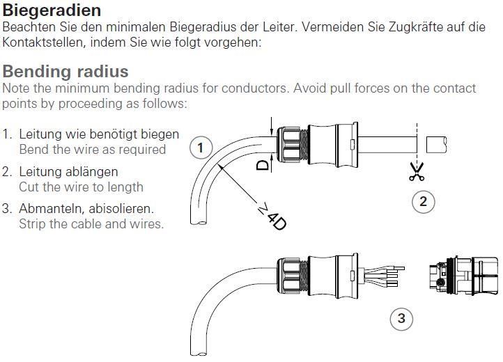
TGL-System E NOT Montageanleitung
Sicherheitshinweise
Diese Anleitung setzt Fachkenntnisse voraus, die einer abgeschlossenen
Berufsausbildung im Elektrohandwerk entsprechen!
Arbeiten Sie niemals bei anliegender Spannung an der Leuchte.
Vorsicht-Lebensgefahr!
Bei Störungen des LED-Moduls wenden Sie sich bitte an AS LED Lighting zum Austausch der Module.
Leitungen nicht auf die Leuchte legen.
Für die Installation und für den Betrieb der Leuchten sind die nationalen Sicherheitsvorschriften zu beachten.
Wichtige Hinweise zu elektronischen Betriebsgeräten (EVG)
Eine Neutralleiterunterbrechung im Drehstromkreis führt zu Überspannungsschäden in der Beleuchtungsanlage. Neutralleiter – Trennklemme
deshalb nur spannungsfrei öffnen und vor Wiedereinschalten schließen.
Die maximal zulässige Umgebungstemperatur ta der Leuchte darf nicht überschritten werden. Überschreitung reduziert die Lebensdauer, im
Extremfall droht Frühausfall.
Anschlussleitungen für Steuereingänge dimmbarer LED-Treiber (1-10V, Dali, etc.) 230V netzspannungsfest auslegen.
Safety notes
These instructions assume expert knowledge corresponding to a completed professional education as an electrician.
Never work when voltage is present on the luminaire.
Caution – Risk of fatal injury!
In case of malfunctions with the LED module, please contact us, changing the modules.
Do not place any cables on the luminaire.
Please note national safety instructions for installation and operation of this luminaire.
Important Information Regarding Electronic Control Gear (ECG)
Interference to the neutral conductor in a three-phase system may result in surge-related damage in the lighting installation. Only open neutral
conductor –disconnect terminal when disconnected from power supply and close prior to switching back on.
The maximum admissible ambient temperature ta of the luminaire may not be exceeded. Surpassing that temperature reduces the service life
and, in extreme cases, poses risk of early failure.
Use mains cables for control inputs of dimmable LED-Driver (1-10V, Dali, etc.) which are rated for 230V.
Bestimmungsgemäße Verwendung
Die Leuchte TGL ist für Aussenbereiche und Feuchträume mit der
Umgebungstemperatur von -25°C bis +50°C bestimmt.
Die Tragfähigkeit der Decke muss durch bauseitige Maßnahmen sichergestellt sein.
Technische Änderungen behält sich die AS LED Lighting GmbH vor.
Der Hersteller übernimmt keine Haftung für Schäden, die durch unsachgemäßen Einsatz entstehen.
Die Lichtquelle/Batterie dieser Leuchte darf nur vom Hersteller oder einem von ihm beauftragten Servicetechniker oder einer vergleichbaren
Fachkraft ersetzt werden.
Intended use
The TGL luminaire is intended for outdoor applications and wet rooms at an ambient temperature of -25°C to +50°C .
The ceiling carrying capacity must be secured by appropriate building measures.
Further modification for technical specification only by AS LED Lighting GmbH.
The manufacturer bears no liability for damage caused by inappropriate use or application.
The light source and battery of this luminaire may only be replaced by the manufacturer or by a service technician appointed by him or a
comparable specialist.
https://www.as-led.de/ Seite 1 von 14 Rev. 16.03.2021
TGL-System E NOT                                        Montageanleitung
 Leuchten Typen
 Luminaire types
                                                            L         L1      B1          H          A
                           Modellbezeichnung
                                                          (mm)      (mm)     (mm)       (mm)       (mm)
        TGL-060010-xxx-02-MLH/MLD-E                        689       645      102        93         650
        TGL-060010-xxx-02-MLH/MLD-E-opal                   689       645      102        93         650
        TGL-090010-xxx-03-MLH/MLD-(DALI)-E                 969       925      102        93         930
        TGL-090010-xxx-03-MLH/MLD-(DALI)-E-opal            969       925      102        93         930
        TGL-120010-xxx-04-MLH/MLD-(DALI)-E                1249      1205      102        93        1210
        TGL-120010-xxx-04-MLH/MLD-(DALI)-E-opal           1249      1205      102        93        1210
        TGL-150010-xxx-05-MLH/MLD-(DALI)-E                1529      1480      102        93        1490
        TGL-150010-xxx-05-MLH/MLD-(DALI)-E-opal           1529      1480      102        93        1490
                      xxx = 830/840/850/865

 Lieferumfang
 Scope of delivery
 https://www.as-led.de/

                                       Anbauflansch
                                      mounting flange
                                                                             1x
                  3x

                          6x

              Senkkopfschraube M5x14 Torx T20                              Wieland Anschlussbuchse
                  countersunk head screw                                       RST20i5, schwarz
                                                                           Wieland connection socket
                                                                                RST20i5, black

 Abmessungen und Vorbereitung
 Dimensions and Preparation

https://www.as-led.de/                             Seite 2 von 14                                      Rev. 16.03.2021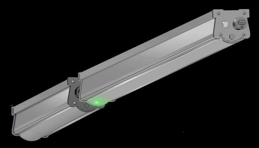
TGL-System E NOT                                       Montageanleitung

        Bohrungsmaße TGL
                   Abstand              Max. Bohrmaß        Min. Bohrmaß
       Typ                                                                    Länge [L1]          Länge [A1]            Länge [L]
                  Bohrung [A]                [D]                 [C]
  TGL-060010          655                    665                 640              645                  440                 689
  TGL-090010          935                    945                 920              925                  440                 969
  TGL-120010         1215                   1225                1200             1205                  440                1249
  TGL-150010         1495                   1505                1480             1485                  440                1529

 Montage Befestigungsflansch auf die Leuchte
 Attach the mounting flange on the luminaire

                                   2                Befestigungsflansch auf Leuchte schrauben.
                                                    Screw the mounting flange on the luminaire.

                1

                                                                                                             2

                                                                                                                 1

 Decke bohren                                               Montage Dübel
 Drill the ceiling                                          Mounting dowels

                                                                               A1
                                      1                                                            A

                            A1

                                             A
                                                                        2
                                                                                      2
                                                                                                                 2

                                                                        Dübel und/oder Schrauben für die Deckenmontage
                                                                                nicht im Lieferumfang enthalten.
       Abstand Bohrung A und A1 siehe Bild 4 auf Seite 3.                 Dowels and/or screws for ceiling mounting are
        Find dimension A and A1 in picture 4 on page 3.                            not included in the delivery.

https://www.as-led.de/                            Seite 3 von 14                                                     Rev. 16.03.2021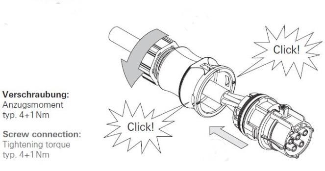
TGL-System E NOT                            Montageanleitung
 Leuchte Deckenmontage
 Mounting the luminaire on ceiling

             1                                          A
                                                        1

                                                                                   1

               2

                                                                                   2
                         Abstand Bohrung A siehe Bild 4 und 5 auf Seite 2 und 3.
                          Find dimension A in picture 4 and 5 on page 2 and 3.

 Befestigungsflansch auf Batterie montieren
 Attach mounting flange on battery

                                           2

                                               1

https://www.as-led.de/                 Seite 4 von 14                                  Rev. 16.03.2021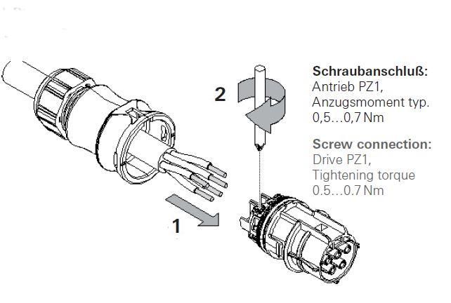
TGL-System E NOT                                       Montageanleitung
 Batteriepack mit Leuchte verbinden
 Connect battery pack with luminaire

                                                                   1

 Batterie an der Decke befestigen
 Fix battery to the ceiling

                                                            A1

                                                     2

             Abstand Bohrung A1 siehe Bild 4 auf Seite 3.
              Find dimension A1 in picture 4 on page 3.

https://www.as-led.de/                            Seite 5 von 14          Rev. 16.03.2021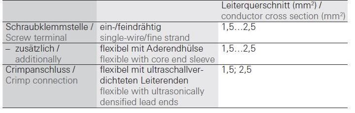
TGL-System E NOT Montageanleitung
Anschlußbelegung Buchse (5-polig) Abmantellängen und Abisolierlängen (mm)
Pin assignments of the socket (5-pole) Dismantling and Insulation strip lengths (mm)
Belegung 230V Bezeichnung Farbe
Netzanschlußseite Anschlußbuchse colour
Pin assignment 230V und Klemme
powerside
L ( unswitched line ) 2 schwarz (black)
Neutralleiter N blau ( blue )
Erdung GND PE grün–gelb ( green-
yellow )
S / L ( switched line) 1 braun ( brown )
Unbelegt ( not used ) 3
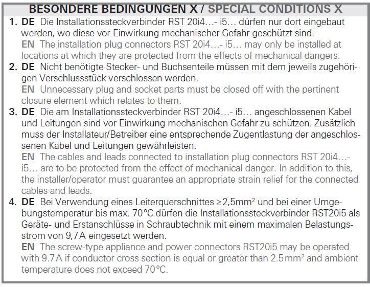
Schraub-Anschlüsse
Technische Spezifikationen Anschließbare Leiterarten
Technical specifications Type of conductors which can be connected
Anschließbare Querschnitte (mm²) Bemessungsstrom
Connectable cross sections (mm²) Rated current
https://www.as-led.de/ Seite 6 von 14 Rev. 16.03.2021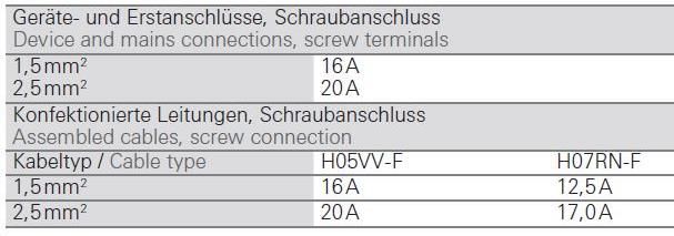
TGL-System E NOT                               Montageanleitung
 Biegeradien                                          Leitermontage - Buchse
 Bending radius                                       Wire connection - socket

                                                                          2

                                                                      1

                                                                       Wieland Anschlussbuchse
                                                                           RST20i5, schwarz
                                                                       Wieland connection socket
                                                                            RST20i5, black
                                                                          2
 Verschließen                                         Stecken und verriegeln
 Closing                                              Pluging and locking

                         2

                               1
               Wieland Anschlussbuchse
                   RST20i5, schwarz                                              1
               Wieland connection socket
                    RST20i5, black                                         Wieland Anschlussbuchse
                                                                               RST20i5, schwarz
                                                                           Wieland connection socket
                                                                                RST20i5, black

https://www.as-led.de/                     Seite 7 von 14                                    Rev. 16.03.2021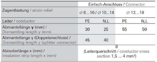
TGL-System E NOT                                Montageanleitung
 Entriegel und Trennen                                       Öffnen des Steckverbinders
 Unlocking and separating                                    Opening the connector

                                                                                                2
                                     1

                                                               1

                           2
 Überwachung Notlicht-Funktion
 Monitoring emergency light function

                                                                    Bei Leuchten in Standard-Ausführung zeigt die
                                                                    grüne Leuchtdiode ( LED ) die korrekte
                                                                    Batterieladung an. Bleibt die LED dunkel, ist die
                                                                    Ladung durch fehlende Netzspannung oder
                                                                    defekter Ladeeinheit nicht gewährleistet.

                                                                    In the case of lights in standard design, the green
                                                                    light-emitting diode ( LED ) indicates the correct
                                                                    battery charge. If the LED remains dark, charging
                                                                    is not guaranteed due to lack of mains voltage or
                                                                    defective charging unit.

                            Status-LED
                         Grün: System OK
                            Status LED
                         Green: System OK

https://www.as-led.de/                      Seite 8 von 14                                                 Rev. 16.03.2021
TGL-System E NOT Montageanleitung
Information zur Notlichtfunktion
Information on the emergency light function
Werkseinstellung für die Dauer des Notlichtes
Factory setting for the duration of the emergency light 3h
Erstladung des Akkus
Initial charging of the battery 20h
Schnellaufladung
Quick charge 15h
Erhaltungsladung Kontinuierlich
Trickle charge continuous
Prüftaster
Checks master
Ausführen eines Funktionstests solange der Taster gedrückt ist leuchtet die TGL im Notlichtbetrieb.
Performing a function test as long as the button is pressed, the TGL lights up in emergency lighting
mode.
Taster loslassen Leuchte schaltet in den Normalbetrieb um grüne LED leuchtet konstant.
Release button Luminaire switches to normal operation Green LED lights up constantly.
Hinweis:
Der Prüftaster in der leuchte kann je nach Baureihe entfallen!
Dieser ist dann nach EN 1838 durch einen eigenen zentralen Prüftaster
mit Öffner-Funktion zu montieren und darf nicht durch den Sicherungsautomaten oder den
Fehlerstrom-Schutzschalters des Stromkreises ersetzt werden.
Note:
The test button in the lamp may be omitted depending on the series!
In accordance with EN 1838, this must then be fitted with its own central test button
with normally closed function and must not be replaced by the circuit breaker or the residual
current circuit breaker of the circuit.
Inbetriebnahme
Start-up
Nach der Installation der Leuchte und dem ersten Anschluss der Netzversorgung und des Akkus an den EM Converter-LED wird das Gerät damit beginnen
den Akku 20 Stunden lang zu laden (Erstladung). Anschließend muss am Gerät einen Inbetriebnahmetest durchgeführt werden. Die 20 Stunden
Wiederaufladung passiert ebenso wenn ein neuer Akku angeschlossen wird, oder das Gerät den rest mode (Ruhebetrieb) verlässt. Der folgende
automatische Inbetriebnahmetest wird nur durchgeführt wenn ein Akku ersetzt und voll geladen wurde (nach 20 Std.) und die Intervallzeit nicht auf null
gesetzt ist.
After the installation of the lamp and the first connection of the mains supply and the battery to the EM Converter-LED, the device will start charging the
battery for 20 hours (initial charge). After that, a commissioning test must be performed on the device. The 20 hours recharge also happens when a new
battery is connected or the device leaves the rest mode (idle mode). The following automatic commissioning test is only performed if a battery has been
replaced and fully charged (after 20 hours) and the interval time is not set to zero.
https://www.as-led.de/ Seite 9 von 14 Rev. 16.03.2021TGL-System E NOT Montageanleitung
Sicherungsautomat C10 C13 C16 C20 B10 B13 B16 B20 Einschaltstrom
Installation Ø 1,5 mm² 1,5 mm² 2,5 mm² 2,5 mm² 1,5 mm² 1,5 mm² 2,5 mm² 2,5 mm² Imax Pulsdauer
Anzahl Leuchten:
TGL-090010-830-03-MLD-E-NOT 12 18 24 28 6 9 12 14 25,8 A 280 µs
TGL-090010-830-03-MLH-E-NOT 12 18 24 28 6 9 12 14 25,8 A 280 µs
TGL-090010-840-03-MLD-E-NOT 12 18 24 28 6 9 12 14 25,8 A 280 µs
TGL-090010-840-03-MLH-E-NOT 12 18 24 28 6 9 12 14 25,8 A 280 µs
TGL-090010-850-03-MLD-E-NOT 12 18 24 28 6 9 12 14 25,8 A 280 µs
TGL-090010-850-03-MLH-E-NOT 12 18 24 28 6 9 12 14 25,8 A 280 µs
TGL-090010-865-03-MLD-E-NOT 12 18 24 28 6 9 12 14 25,8 A 280 µs
TGL-090010-865-03-MLH-E-NOT 12 18 24 28 6 9 12 14 25,8 A 280 µs
TGL-120010-830-04-MLD-E-NOT 12 18 24 28 6 9 12 14 25,8 A 280 µs
TGL-120010-830-04-MLH-E-NOT 12 18 24 28 6 9 12 14 25,8 A 280 µs
TGL-120010-840-04-MLD-E-NOT 12 18 24 28 6 9 12 14 25,8 A 280 µs
TGL-120010-840-04-MLH-E-NOT 12 18 24 28 6 9 12 14 25,8 A 280 µs
TGL-120010-850-04-MLD-E-NOT 12 18 24 28 6 9 12 14 25,8 A 280 µs
TGL-120010-850-04-MLH-E-NOT 12 18 24 28 6 9 12 14 25,8 A 280 µs
TGL-120010-865-04-MLD-E-NOT 12 18 24 28 6 9 12 14 25,8 A 280 µs
TGL-120010-865-04-MLH-E-NOT 12 18 24 28 6 9 12 14 25,8 A 280 µs
TGL-150010-830-05-MLD-E-NOT 12 18 24 28 6 9 12 14 25,8 A 280 µs
TGL-150010-830-05-MLH-E-NOT 12 18 24 28 6 9 12 14 25,8 A 280 µs
TGL-150010-840-05-MLD-E-NOT 12 18 24 28 6 9 12 14 25,8 A 280 µs
TGL-150010-840-05-MLH-E-NOT 12 18 24 28 6 9 12 14 25,8 A 280 µs
TGL-150010-850-05-MLD-E-NOT 12 18 24 28 6 9 12 14 25,8 A 280 µs
TGL-150010-850-05-MLH-E-NOT 12 18 24 28 6 9 12 14 25,8 A 280 µs
TGL-150010-865-05-MLD-E-NOT 12 18 24 28 6 9 12 14 25,8 A 280 µs
TGL-150010-865-05-MLH-E-NOT 12 18 24 28 6 9 12 14 25,8 A 280 µs
Tabelle gilt für transparente und opale Ausführung.
The table applies to transparent and opal version
Wartung und Prüfung
Maintenance and testing
Es sind für Unterhalt und Kontrolle die Vorschriften und Normen für Sicherheitsleuchten am Montageort zu
beachten.
The regulations and standards for safety luminaires at the installation site must be observed for maintenance and
inspection.
Tägliche Prüfung
Sichtprüfung der Anzeigen bei Zentralen Stromversorgungsanlagen auf korrekte Funktion.
Daily check
Visual inspection of the indicators on central power supply systems for correct operation.
Monatliche Prüfung
Wird eine automatische Prüfeinrichtung eingesetzt, sind die Funktionstests Ergebnisse zu protokollieren
Die Monatliche Prüfung muss wie folgt durchgeführt werden:
- Durch Simulation eines hinreichenden langen Stromausfalls der allgemeinen Beleuchtung muss die Umschaltung jeder Leuchten von
Netzbetrieb auf Notbetrieb, und die Funktion derselben geprüft werden.
- In dieser Zeit müssen alle Leuchten und Zeichen auf Sauberkeit, Vorhandensein und richtige Funktion geprüft werden
- Nach Abschluss der Prüfung sollte die allgemeine Beleuchtung wieder hergestellt werden, und zusätzliche jede Meldelampe und jedes
Meldegerät geprüft werden, um Sicherzustellen, dass die allgemeine Energieversorgung wieder hergestellt ist.
https://www.as-led.de/ Seite 10 von 14 Rev. 16.03.2021TGL-System E NOT Montageanleitung Monthly test If automatic test equipment is used, the functional tests results must be recorded Monthly testing shall be performed as follows: - By simulating a sufficiently long power failure of the general lighting system, the changeover of each luminaire from mains operation to emergency operation, and the function of the same shall be tested. - During this time, all lights and signs must be checked for cleanliness, presence and proper function - Upon completion of the test, the general lighting should be restored, and additionally each annunciator lamp and sign should be tested to ensure that the general power supply has been restored. Jährliche Prüfung Wird eine automatische Prüfeinrichtung eingesetzt, sind die Bemessungsbetriebsdauertests Ergebnisse zu protokollieren. Alle anderen Systeme müssen die monatlichen Prüfungen sowie die nachfolgenden zusätzlichen Prüfungen und Tests durchgeführt werden: - Jede Leuchte und jedes hinterleuchtete Zeichen muss über seine volle, vom Hersteller angegebene Bemessungsbetriebsdauer geprüft werden - Nach Abschluss der Prüfung sollte die allgemeine Beleuchtung wieder hergestellt werden, und zusätzlich jede Meldelampe und jedes Meldegerät geprüft werden, um Sicherzustellen, dass die allgemeine Energieversorgung wieder hergestellt ist. - Datum der Prüfung und Ergebnisse müssen im Prüfbuch niedergeschrieben werden. Annual test If automatic test equipment is used, the design service life test results shall be recorded. All other systems shall have the monthly inspections and subsequent additional inspections and tests performed: - Each luminaire and backlit sign shall be tested for its full rated service life as specified by the manufacturer. - Upon completion of the test, general illumination should be restored, and in addition, each annunciator lamp and annunciator device should be tested to ASSURE that general power is restored. - The date of the test and the results must be recorded in the test book. Informationen über Wartung und Überprüfung der in der Leuchte verbauten Akkumulatoren entnehmen Sie dem folgenden link: https://www.tridonic.com/com/de/download/data_sheets/Accu_NiCd_4.5Ah_de.pdf For information on maintenance and inspection of the accumulators installed in the light Batteries can be found in the following link: https://www.tridonic.com/com/de/download/data_sheets/Accu_NiCd_4.5Ah_de.pdf https://www.as-led.de/ Seite 11 von 14 Rev. 16.03.2021
TGL-System E NOT                                                  Montageanleitung
 Prüfbuch
 Inspection book

 Für eine Sicherheitsbeleuchtungsanlage muss der Besitzer oder Eigentümer eine Person benennen, welche verantwortlich für die Anlage ein Prüfbuch führt,
 und dieses auf Verlangen entsprechender bevollmächtigter Personen zur Einsicht auflegt.

 In einen Prüfbuch müssen folgende Informationen enthalten sein:

 - Datum der Inbetriebnahme inkl. Bescheinigungen über Änderungen

 - Datum jeder wiederkehrenden Prüfungen und jedes Tests

 - Datum und kurzgefasste Informationen über jede Wartung, Prüfung und Test

 - Datum und kurzgefasste Informationen über jeden Fehler und die Fehlerbehebung

 - Datum und kurzgefasste Informationen über Änderungen an der Sicherheitsbeleuchtungsanlage

 - Sollte eine automatische Prüfeinrichtung vorhanden sein und verwendet werden, müssen Hauptmerkmale und Arbeitsweise dieses Gerätes beschrieben
 sein

 For a safety lighting system, the owner or proprietor shall designate a person who shall be responsible for maintaining an inspection book for the system
 and shall make it available for inspection upon request of appropriate authorized persons.

 An inspection book must contain the following information:

 - Date of commissioning incl. certificates of modifications

 - Date of each periodic inspection and test

 - Date and brief information about each maintenance, inspection and test

 - Date and brief information on each fault and fault rectification

 - Date and summary information of any changes made to the safety lighting system.

 - If an automatic test device is present and used, the main characteristics and operation of this device must be described

https://www.as-led.de/                                     Seite 12 von 14                                                              Rev. 16.03.2021
TGL-System E NOT                                                 Montageanleitung
 Installationshinweis
 Installation information
           Die Lichtquelle/die Module dieser Leuchte sind austauschbar. Wenn die Lichtquelle ihr Lebensdauerende erreicht hat, können die Module ersetzt
           werden. Die Lichtquelle dieser Leuchte darf nur vom Hersteller oder einem von ihm beauftragten Servicetechniker oder einer vergleichbaren
           Fachkraft ersetzt werden.

           The luminaire light source (s) are interchangeable. When the light source has reached its end of life, the modules can be replaced. The light source of
           this luminaire may only be replaced by the manufacturer or by a service technician appointed by him or a comparable specialist.

            “Vorsicht, Gefahr des elektrischen Schlags!”
             Achtung, gefährliche Spannung > 65Vdc!
             Arbeiten an der Leuchte dürfen nur im spannungslosen Zustand durchgeführt werden und
             setzen Fachkenntnisse voraus, die einer abgeschlossenen Berufsausbildung im Elektrohandwerk entsprechen!

           „Caution, risk of electric shock“
           Caution, dangerous voltage> 65Vdc!
           Work on the luminaire must only be carried out in a tension - free state.
           These instructions assume expert knowledge corresponding to a completed professional education as an electrician.

            Nicht zur Abdeckung mit Wärmedämm-Material geeignete Leuchte.

            Not suitable for covering with heat-insulating material.

           Das Symbol der durchgestrichenen Mülltonne auf Rädern bedeutet, dass das Produkt in der EG einer getrennten Müllsammlung zugeführt
           werden muss. Dies gilt für das Produkt und alle mit diesem Symbol gekennzeichneten Zubehörteile. Gekennzeichnete Produkte dürfen nicht
           über den normalen Hausmüll entsorgt werden, sondern müssen einer Annahmestelle für das Recycling von elektrischen und elektronischen
           Geräte entsorgt werden.

           The symbol of the crossed-out wheeled bin means that the product must be sent to a separate waste collection point in the EC. This applies to the
           product and all accessories marked with this symbol. Marked products may not be disposed of with normal household waste, but must be disposed of
           at a collection point for the recycling of electrical and electronic equipment.

 Für die Anwendung diverser Zubehöre sowie weitere Hinweise für die Installation in Aussenbereichen finden Sie weiter Hinweise auf der Homepage des
 Herstellers unter:
 For using diverse accessories and finding further information for outdoor installations go to the manufacturer homepage at:

 https://eshop.wieland-electric.com/wielandCategories

https://www.as-led.de/                                     Seite 13 von 14                                                                   Rev. 16.03.2021
TGL-System E NOT Montageanleitung
Kennzeichnung
Label
Unsere Einzelbatterie-Leuchten sind entsprechend den aktuellen gültigen Leuchtenbauvorschriften gekennzeichnet. Die Kennzeichnung ist wie
folgt:
Our single battery luminaires are marked according to the current valid luminaire construction regulations. The marking is as follows:
Feld 1: Bauart
Feld 2: Betriebsart
Feld 3: Einrichtungen wie Selbsttest u.s.w.
Feld 4: Betriebsdauer
Feld 5: Akku-Typ mit Spannungsangabe und Leistungsangabe
Field 1: Type
Field 2: Operating mode
Field 3: Equipment such as self-test, etc.
Field 4: Operating time
Field 5: Battery type with voltage and power information
https://www.as-led.de/ Seite 14 von 14 Rev. 16.03.2021Sie können auch lesen