Digitaler Druckregler Digital Pressure Regulator - mit Anzeige und Einstelltasten with display and controls - ASCO Numatics
←
→
Transkription von Seiteninhalten
Wenn Ihr Browser die Seite nicht korrekt rendert, bitte, lesen Sie den Inhalt der Seite unten
Digitaler Druckregler
SentronicLP IO-Link CLASS A - Baureihe 617
      mit Anzeige und Einstelltasten
      Digital Pressure Regulator
 SentronicLP IO-Link CLASS A - 617 Series
         with display and controls

                           Installationshandbuch
                             Installation manual

                                IM502079-009 / R02

                                    DE GB
DE
                                                                                                                                                  INSTALLATION

                                                                                 Inhalt
   1.      BESCHREIBUNG...................................................................................................................................................3
           1.1 Artikel-Nr......................................................................................................................................................3
           1.2 Bedienelemente...........................................................................................................................................4
           1.3 Betriebszustände.........................................................................................................................................4
   2.      ELEKTRISCHER ANSCHLUSS.............................................................................................................................4

   3.      SOLLWERT - AUSGANGSDRUCK........................................................................................................................5

   4.      PNEUMATISCHER ANSCHLUSS..........................................................................................................................5

   5.      ANGABEN ZUR WERKSEINSTELLUNG..............................................................................................................5

   6.      TECHNISCHE DATEN...........................................................................................................................................6
           6.1 Fluidtechnische Daten.................................................................................................................................6
           6.2 Kennwerte....................................................................................................................................................6
   7.      ZUBEHÖR..............................................................................................................................................................6

   8.      WARTUNG UND PFLEGE.....................................................................................................................................7

   9.      ABMESSUNGEN UND GEWICHTE......................................................................................................................8

  GB       ENGLISH VERSION.............................................................................................................................................11

                                                                                           Dieses Produkt enthält elektronische Bauteile, die gegenüber elektrostati-

                             A C H T U N G
                                                                                           schen Entladungen (ESD) empfindlich sind. Berührungen der elektrischen
                                                                                           Bauteile durch Personen oder Gegenstände können zu einer elektrostati-
                                                                                           schen Entladung führen, die das Produkt beschädigt oder zerstört.
                                VORSICHT BEI HANDHABUNG
                                                                                           Um das Risiko einer elektrostatischen Entladung zu vermieden, sind die
                                  VON ELEKTROSTATISCH                                      Handhabungshinweise und Empfehlungen nach EN 100015-1 zu beachten.
                                     GEFÄHRDETEN                                           Zum elektrischen Anschließen oder Trennen des Produkts ist die Versor-

ESD                                 BAUTEILEN (EGB)                                        gungsspannung abzuschalten.

              ACHTUNG! Wenn die Programmierschnittstelle am Ventil benutzt wird, können gefährliche Betriebszustände auftreten, da das Ventil

    !
              möglicherweise nicht mehr auf den angelegten Sollwert reagiert.
              Bei Inbetriebnahme und vor Änderungen der Ventileinstellungen sind Vorkehrungen gegen unkontrollierte Bewegung von Anlagenteilen
              zu treffen.

Hiermit erklären wir, dass das in diesem Installationshandbuch beschriebene Gerät in der von uns gelieferten Ausführung zum Einbau oder Zusam-
menbau mit anderen Maschinen bestimmt ist, und dass die Inbetriebnahme so lange untersagt ist, bis festgelegt wurde, dass die Maschine in die das
Gerät eingebaut werden soll, den Bestimmungen der Richtlinie 2006/42/EG entspricht.
Die Handhabung, Montage und Inbetriebnahme, sowie Einstell- und Justierarbeiten dürfen ausschließlich von autorisiertem Fachpersonal durchgeführt
werden.

                Dieses Produkt entspricht der Richtlinie 2014/30/EU und deren Ergänzungen über die Elektromagnetische Verträglichkeit. Es ist nach
                CE zugelassen. Eine Konformitätserklärung steht auf Anfrage zur Verfügung.
                Geben Sie bitte für die entsprechenden Produkte die Artikelnummer und Seriennummer an.

                                                                          ANMERKUNGEN
DIE IN DIESEM HANDBUCH ENTHALTENEN ANGABEN KÖNNEN OHNE VORHERIGE ANKÜNDIGUNG GEÄNDERT WERDEN.
ASCO NUMATICS übernimmt keinerlei Haftung für technische oder redaktionelle Fehler oder Ungenauigkeiten oder für versehentlich entstehende
Schäden oder Folgeschäden, die durch die Bereitstellung dieses Handbuchs oder aus der Anwendung desselben entstehen.
DAS VORLIEGENDE HANDBUCH ENTHÄLT URHEBERRECHTLICH GESCHÜTZTE ANGABEN. KEIN TEIL DIESES HANDBUCHS DARF OHNE
VORHERIGE SCHRIFTLICHE GENEHMIGUNG VON ASCO NUMATICS AUF IRGENDEINE ART UND WEISE VERVIELFÄLTIGT ODER ÜBERTRA-
GEN WERDEN.
                                     COPYRIGHT © 2018 - ASCO NUMATICS - Alle Rechte vorbehalten.

IM502079-009-2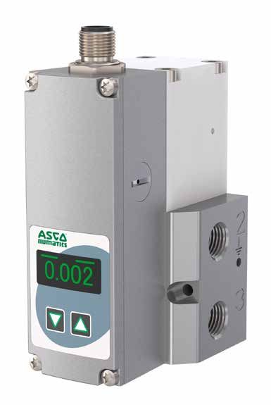
DE
INSTALLATION

1.   BESCHREIBUNG

     Das Sentronic LP-Ventil arbeitet mit getakteten Pilotventilen, die den Druck in einer Steuerkammer verändern.
     Ein nachgeschalteter Durchflussverstärker (Druckbooster) setzt den Steuerdruck in einen Ausgangsdruck um.
     Der Ausgangsdruck wird über einen Drucksensor gemessen und dem integrierten digitalen Regelkreis zugeführt.

     Sentronic LP eignet sich besonders für Druckregelungen, bei denen ein konstanter Druck bei unterschiedlichen
     Durchflüssen benötigt wird, wie Luftdosierung über Düsen, Turbinendrehzahlregelung.
     Mit Hilfe der verfügbaren DaS-Software (Data Acquisition Software) kann das Ventil bei Bedarf an die Applikation
     angepasst werden.

     •     Die Druck- und Entlüftungsanschlüsse sind in derselben Größe ausgeführt, was sowohl bei der Erhöhung als
           auch bei der Verringerung des Drucks zu kurzen Ansprechzeiten führt.
     •     Digitale Drucksteuerung im geschlossenen Kreis: Ein interner Drucksensor misst den Ausgangsdruck. Der
           Ausgangsdruck wird in Echtzeit eingeregelt.
     •     Regelparameter können mit IO-Link Master oder über die DaS-Software geändert werden. Diese Flexibilität
           ermöglicht es, das Ventil an die verschiedensten Anwendungen anzupassen und die Ansprechzeit, das Über-
           schwingen und die Präzision des Ventils zu optimieren.
     •     Nach der Bestimmung der optimalen Parameter können diese zum persönlichen Gebrauch in einer Projekt-
           Datei gespeichert werden, die auch für eine zukünftige Serien-Produktion an unsere Abteilung Product Support
           eingesandt werden kann.

1.1 ARTIKEL-NR.

                                            G     617   A    C   S   I   O    I   XXX PP
     Gewindeanschluss                                                                       Max. Eingangsdruck
     G = ISO 228                                                                            03 = 5 bar
     8 = NPT                                                                                06 = 8 bar
                                                                                            10 = 12 bar
     Baureihe
     617                                                                                    Optionen
                                                                                            A00 = Standard
     Revisionsbuchstabe                                                                     A07 = Sauerstoffrein1
     A = Erstfreigabe
                                                                                            Eingang / Display mit Tasten
     Ausführung (Anschluss)                                                                 0 = mit Display
     0 = Flansch + Druckhaltend (DN4)                                                       1 = ohne Display
     4 = 1/4 + Druckhaltend (DN4)
     6 = 3/8 + Druckhaltend (DN8)                                                           Ausgang
     8 = 1/2 + Druckhaltend (DN15)                                                          1 = Standard
     J = Flansch + Druckhaltend (DN4), externer Druckanschluss
     F = 1/4 + Druckhaltend (DN4), externer Druckanschluss
     G = 3/8 + Druckhaltend (DN8), externer Druckanschluss
     H = 1/2 + Druckhaltend (DN15), externer Druckanschluss

     Sollwert
     8 = IO-Link Class A

     Istwert
     6 = IO-Link Class A

     1)   nur bei Ausführung G1/4 (DN4) möglich

                                                                                                           IM502079-009-3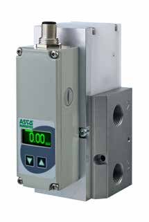
DE
INSTALLATION
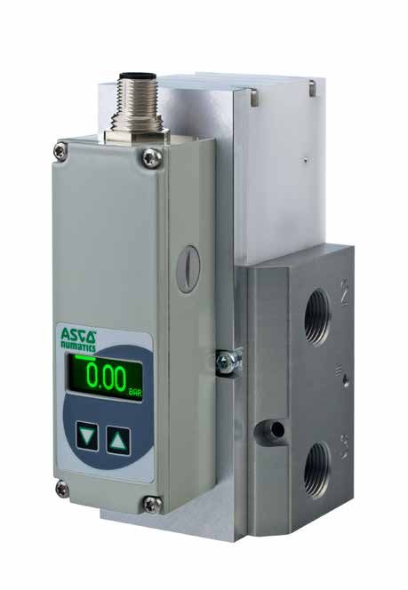
1.2 BEDIENELEMENTE
1 IO-Link Schnittstelle, M12-Stecker
1
2 Druckausgang
3 Schutzerde – Anschluss, M4
4 Entlüftung
5 Druckversorgung
6 LC-Display
7 Bedientasten
8 Befestigung
2
6 3 Das Ventilgehäuse ist mit Hilfe der Erdungsklem-
5 me Nr.3 (ØM4) zu erden.
7 8
4
1.3 BETRIEBSZUSTÄNDE
Shutoff:
Wird der Sollwert kleiner 0,5 %, so wird das Ventil entlüftet und nach 10s das Enlüftungsventil stromlos geschaltet.
Übertemperatur:
Erreicht die interne Regelelektronik eine Temperatur größer 100 °C, so wird die Regelung eingeschränkt, um eine
weitere Erhitzung zu vermeiden.
2. ELEKTRISCHER ANSCHLUSS
PINBELEGUNG IO - LINK SCHNITTSTELLE
1 4 Pin Beschreibung
1 24V-Spannungsversorgung
5 2 nicht belegt
3 Versorgung Masse
2 3 4 C/Q
5 nicht belegt
Gehäuse EMV-Abschirmung
IM502079-009-4DE
INSTALLATION
3. SOLLWERT - AUSGANGSDRUCK
Sollwert-Nullpunkt
Der Einstellbereich für den Nullpunkt ist maximal 0% bis +100%.
WARNUNG: Ausgangsdrücke größer als PMR (Pressure Maximum Range) werden vom Ventil nicht geregelt, d.h.
der max. Ausgangsdruck wird auf PMR begrenzt.
Um eine Beschädigung des Sensors zu vermeiden, sollte der Versorgungsdruck immer kleiner als der ma-
ximale Eingangsdruck (MAP) sein.
Sollwert-Spanne
Die Druck-Spanne des Sollwerts kann über die DaS-Software verändert werden. Hierzu im Abschnitt "Sollwert-
einstellung" auf "Kunde" umschalten. Der Einstellbereich für die Spanne ist 10 % bis 100%.
4. PNEUMATISCHER ANSCHLUSS
Die pneumatische Durchflussrichtung ist von Anschluss 1 nach 2.
1 Druckversorgung Anschluss 1
2 Druckausgang Anschluss 2
3 Entlüftung Anschluss 3
2
1
3
Es sind zöllige Verschraubungen (Rohrgewinde) zu verwenden.
Jede Verschraubung ist mit einem passenden Kunststoffdichtring zu unterlegen.
Teflondichtband und Hanf dürfen nicht verwendet werden, da sie in das Innere des Ventils gelangen können.
An der Entlüftung (3) ist ein passender Schalldämpfer zu verwenden. Je nach verwendetem Schalldämpfer kann
sich die Entlüftungszeit verlängern.
Der Querschnitt der Pneumatikleitungen ist der Nennweite des Ventils anzupassen. Die Ausgangsleitung (2) sollte
im Querschnitt größer oder gleich der Eingangsleitung (1) sein.
Der Versorgungsdruck muss immer geringer als der in der Tabelle (siehe Abschnitt 1.1) angegebene Wert sein,
jedoch immer größer als der gewünschte Ausgangsdruck.
5. ANGABEN ZUR WERKSEINSTELLUNG
- Ausgangsdruck 0 bar bei einem Sollwert von 0
- Spanne: 3 bar-Gerät = 3 bar
6 bar-Gerät = 6 bar
10 bar-Gerät = 10 bar
- Minimale Hysterese
- Die Regelparameter, der Nullpunkt und die Spanne sind werkseitig programmiert.
Parametersatz: Werk
Nullpunkt: 0 %
Spanne: 100 %
Sollwertrampe: keine
Shutoff: EIN; bei Sollwert kleiner 0,5 % entlüftet das Ventil
Reglerstruktur: PID
IM502079-009-5DE
INSTALLATION
6. TECHNISCHE DATEN
KONSTRUKTIONSMERKMALE
Gehäuse Aluminium
Innenteile POM (Polyacetal)
Dichtungen NBR (Nitril)
6.1 FLUIDTECHNISCHE DATEN
Medium Luft oder neutrales Gas, gefiltert, nach ISO 8573-1:2010 [7:4:4]
Maximaler Eingangsdruck Mind. 1 bar höher als max. Ausgangsdruck
Druckbereich 0-3 bar, 0-6 bar, 0-10 bar
Temperatur / Medium 0°C bis +60°C
Temperatur / Umgebung 0°C bis +50°C
Durchfluss (Qv bei 6 bar) 470 Nl/min - 5200 Nl/min
Sollwert Digitaler Sollwert in 1 mbar Schritten
0-10000 = 0-10 bar
Hysterese 1,5% vom Endwert
Linearität 1,5% vom Endwert
Reproduzierbarkeit 1,5% vom Endwert
Mindest-Sollwert 0,5% vom Endwert mit Shutoff-Funktion
Mindest-Ausgangsdruck 1% vom Endwert
Failsafe-Verhalten Druckhaltend bei Spannungsausfall, ohne Regelung
IO-Link
Protokollversion Spezifikation V1.1
Baudrate COM3 (230,4 kBaud)
Minimale Zykluszeit 0,5 ms
Prozessdaten 2 Byte IN, 2 Byte OUT
Porttyp Class A
6.2 KENNWERTE
ELEKTRISCHE DATEN
Spannung Leistungsaufnahme Stromaufnahme Isolations-
Nennweite DN (mm) Schutzart Kabelanschluss
(ausgeregelt) * (W) (mA) klasse
3,8 W 5-polige Leitungsdose M12
4, 8 und 15 24VDC 160 H IP 65 (separat zu bestellen)
(< 1W ausgeregelt)
* Restwelligkeit: 10 %
KENNDATEN
Ø Ø Durchfluss
Anschluss Nennweite DN (mm) KV-Wert (Nm3/h) bei 6 bar (Nl/min)
G/NPT 1/4 4 0,43 470
G/NPT 3/8 8 1,2 1300
G/NPT 1/2 15 4,8 5200
Prüfbedingungen gemäß ISO 8778: Temperatur: 20 °C, relativer Eingangsdruck: 6 bar, relativer Ausgangsdruck: 5 bar
7. ZUBEHÖR
Beschreibung Artikel-Nr.
Anschlussleitung 5m, Buchse gerade offenes Ende N15183710000000
Anschlussleitung 10m, Buchse gerade offenes Ende N15183840000000
Anschlussleitung 5m, Buchse gerade auf Stecker gerade N15184490000000
Anschlussleitung 10m, Buchse gerade auf Stecker gerade N15184520000000
Anreihgrundplatte für 617 DN4 mit G 3/8" Druckluftversorgung N50781800000000
IM502079-009-6DE
INSTALLATION
8. WARTUNG UND PFLEGE
MONTAGE- UND BEDIENUNGSHINWEISE
1. Vor der Inbetriebnahme sorgfältige Kontrolle der elektr. Anschlüsse und der Versorgungsspannung (24
VDC ±10%). Überspannung kann die Elektronik zerstören.
Empfohlene Vorsicherung min. T 0.5 A
2. Der elektrische Anschluss erfolgt über einen Rundstecker M12x1. Der verwendete Stecker muss die Anforde-
rungen nach DIN 60079-15 erfüllen.
Sicherheitshinweis:
Der Stecker darf nicht unter Spannung gezogen werden!
3. Für den elektr. Anschluss des Ventils sind abgeschirmte Kabel zu verwenden. Die Schirmanbindung, Stecker
und Schaltschrank sind EMV-gerecht zu erfolgen. Der Ventilkörper ist elektr. auf Masse (PE, Maschinenmas-
se) zu legen. Ansteuerleitungen nicht parallel zu Starkstromleitungen oder Ansteuerleitungen von Servomo-
toren etc. verlegen.
4. Der Leitungsquerschnitt der Versorgungsspannung sollte min. 0.25 mm2 betragen.
Bei langen Zuleitungen ggf. noch größeren Kabelquerschnitt wählen.
5. Sicherstellen, dass das Ventil mit Druck beaufschlagt ist, sobald ein Sollwertsignal dem Ventil vorgegeben
wird (Sollwertvorgabe, ohne dass das Ventil mit Druck beaufschlagt ist, führt zu einer starken Erwärmung
des Ventils).
6. Das Gerät ist werkseitig abgeglichen.
7. Das Gerät muss zur Reparatur ins Werk eingeschickt werden.
SICHERHEITSHINWEISE
Diese Produkte sind ausschließlich in industriellen Druckluftsystemen zu verwenden. Sie sind dort einzusetzen,
wo die unter "Spezifikationen" aufgeführten Druck- und Temperaturwerte nicht überschritten werden. Berück-
sichtigen Sie bitte die entsprechende Druckschriftenseite.
Vor dem Einsatz der Produkte mit Flüssigkeiten sowie bei nicht industriellen Anwendungen, in lebenserhalten-
den- oder anderen Systemen, die nicht in den veröffentlichten Anleitungsunterlagen enthalten sind, wenden Sie
sich bitte direkt an ASCO Numatics.
Durch Missbrauch, Verschleiß oder Störungen können in Hydrosystemen verwendete Komponenten auf ver-
schiedene Arten versagen.
Systemauslegern wird dringend empfohlen, die Störungsarten aller in Hydrosystemen verwendeten
Komponententeile zu berücksichtigen und ausreichende Sicherheitsvorkehrungen zu treffen, um Verlet-
zungen von Personen sowie Beschädigungen der Geräte im Falle einer solchen Störung zu verhindern.
Systemausleger sind verpflichtet, Sicherheitshinweise für den Endbenutzer im Betriebshandbuch zu vermerken,
wenn der Störungsschutz nicht ausreichend gewährleistet ist.
Systemauslegern und Endbenutzern wird dringend empfohlen, die den Produkten beiliegenden Sicherheitsvor-
schriften einzuhalten.
IM502079-009-7DE
INSTALLATION
9. ABMESSUNGEN UND GEWICHTE
Inline-Version
DN 4
Gewicht: 0,49 kg M6
(2x)
72,7
40
32
8
28
(52)
Programmier-
schnittstelle
115,05
M4 für
Erdungsschraube G1/4
Ø4,2 (3x)
65,5
(2x)
52,8
45
40
25
23
12
17,15 20 35,39 20
43
52
Aufflanschausführung
DN 4
Gewicht: 0,49 kg
72,75
M4
40
(2x)
34,8
78,5
(72,7)
M12 Stecker
Programmier-
schnittstelle
115,05
Ø 6mm
(3x)
M4
(2x)
65,5
40
29,8
25
24
10
6
25 17,15 35,4
M4
Erdungsschraube
IM502079-009-8DE
INSTALLATION
DN 4
Anreihgrundplatte
Gewicht: 0,3 kg
G1/4" 4
32,9
21
5
M6
25,8 (3x)
43 36,8
23 14,2 KM4/ DIN 74 T1 24
0,5 23
(2x)
15
18
28,8
6,3
35,8
40
43,8
44,8
G3/8
58,8
60,8
(4x)
79,1
90
M4 x 8/10
(2x)
Ø6
(3x)
Aufnahme Hutschiene: 10,5
EN 50022
35x7.5 25
25,8
M6
24
(2x)
DN 8
Gewicht: 0,93 kg
Programmier-
schnittstelle
M4 für
Erdungsschraube
129,5
Ø 4,2 (2x) G3/8 (3x)
65,5
77,8
60
58
40
30
14,8
17,15 24,25 46 24,25
57,5
66
56,5
48,5
89,25
IM502079-009-9DE
INSTALLATION
DN 15
Gewicht: 1,33 kg
Programmier-
schnittstelle
M4 für
143,7
Erdungsschraube
Ø 4,2 (2x)
65,5
G1/2 (3x)
92
58
50
32
30
15
17,15 30,5 46 30,5
57,5
66
61
69
101,75
ASCO Numatics GmbH
Otto-Hahn-Straße 7-11
75248 Ölbronn-Dürrn
Germany
Tel: +49 7237 996-0
Email: asconumatics-de@emerson.com
www.asco.com
IM502079-009-10Digital Pressure Regulator
SentronicLP IO-Link CLASS A - 617 Series
with display and controls
Installation manual
IM502079-009 / R02
GBEN INSTALLATION
Content
1. DESCRIPTION.....................................................................................................................................................13
1.1 Catalog number.........................................................................................................................................13
1.2 Operating Elements...................................................................................................................................14
1.3 Operating Modes.......................................................................................................................................14
2. ELECTRICAL CONNECTION..............................................................................................................................14
3. TARGET VALUE - OUTPUT PRESSURE............................................................................................................15
4. PNEUMATIC CONNECTION...............................................................................................................................15
5. INFORMATION ON THE FACTORY SETTINGS..................................................................................................15
6. TECHNICAL CHARACTERISTICS......................................................................................................................16
6.1 Fluid characteristics...................................................................................................................................16
6.2 Key values.................................................................................................................................................16
7. ACCESSORIES....................................................................................................................................................16
8. CARE AND MAINTENANCE................................................................................................................................17
9. DIMENSIONS AND WEIGHTS............................................................................................................................18
C OBSERVE
A U PRECAUTIONS
TION This product contains electronic components sensitive to electrostatic
discharge. An electrostatic discharge generated by a person or object
coming in contact with the electrical components can damage or destroy
FOR HANDLING the product.
To avoid the risk of electrostatic discharge, please observe the handling
ELECTROSTATIC SENSITIVE
precautions and recommendations contained in standard EN 100015‑1.
DEVICES
ESD Do not connect or disconnect the device while it is energised.
CAUTION! Dangerous operating conditions may occur when using the programming interface on the valve as the valve may possibly
not react to the setpoint any more.
! Provide for protection against uncontrolled movement of equipment when putting the valve into operation and before making any
modifications to the valve settings.
We herewith declare that the version of the product described in this installation manual is intended to be incorporated into or assembled with other
machinery and that it must not be put into service until the machinery into which it is to be incorporated has been declared in conformity with the
provisions of Council Directive 2006/42/EC.
Handling, assembly and putting into service and all settings and adjustments must be done by qualified, authorised personnel only.
This product complies with the essential requirements of the EMC Directive 2014/30/EU and its amendments. It is CE-approved.
A separate Declaration of Conformity is available on request.
Please provide ordering code and serial numbers of products concerned.
NOTICE
The information in this manual is subject to change without notice.
In no event shall ASCO NUMATICS be liable for technical or editorial errors or omissions. Neither is any liability assumed for accidental
or consequential damages arising out of or in connection with the supply or use of the information contained herein.
THIS MANUAL CONTAINS INFORMATION PROTECTED BY COPYRIGHT. NO PART OF THIS DOCUMENT MAY BE PHOTOCOPIED
OR REPRODUCED IN ANY FORM OR MANNER WHATSOEVER WITHOUT PRIOR WRITTEN PERMISSION FROM ASCO NUMATICS.
COPYRIGHT © 2018 - ASCO NUMATICS - All rights reserved.
IM502079-009-12INSTALLATION EN
1. DESCRIPTION
The Sentronic LP valve operates with pulsed pilot valves which change the pressure in a control chamber.
A downstream flow amplifier (pressure booster) converts the control pressure into an output pressure. The output
pressure is measured by a pressure sensor and fed to the integrated digital control circuit.
Sentronic LP is particularly suitable for pressure control procedures where a constant pressure is required with
different flow rates, such as air dosing via nozzles or turbine rotation speed control.
Using the available DaS software (Data Acquisition Software), the valve can be adapted to the application if
necessary.
• The pressure connections and the air vent connections are designed in the same size, which results in short
response times both for increasing the pressure and for reducing the pressure.
• Digital pressure control in a closed circuit: An internal pressure sensor measures the output pressure. The
output pressure is adjusted in real time.
• The control parameters can be changed with an IO - Link Master or DaS software. This flexibility makes it
possible to adapt the valve to a very wide range of applications and to optimize the response time and the
precision of the valve and prevent it from overshooting.
• After determining the optimum parameters, these can be saved for personal use in a project file, which can be
sent into our Product Support Department for future series production.
1.1 CATALOG NUMBER
G 617 A C S I O I XXX PP
Thread connection Max. inlet pressure
G = ISO 228 03 = 5 bar
8 = NPT 06 = 8 bar
10 = 12 bar
Product Series
617 Options
A00 = Standard
Revision letter A07 = Oxygen clean1)
A = Initial release
Input / Display with keys
Size 0 = with display
0 = Flange + pressure hold (DN4) 1 = without display
4 = 1/4 + pressure hold (DN4)
6 = 3/8 + pressure hold (DN8) Output
8 = 1/2 + pressure hold (DN15) 1 = Standard
J = Flange + pressure hold (DN4), external pressure
F = 1/4 + pressure hold (DN4), external pressure
G = 3/8 + pressure hold (DN8), external pressure
H = 1/2 + pressure hold (DN15), external pressure
Setpoint
8 = IO-Link Class A
Feedback Type
6 = IO-Link Class A
1) Only possible with size G1/4 (DN4)
IM502079-009-13EN INSTALLATION
1.2 OPERATING ELEMENTS
1 1 IO-Link interface, M12 plug
2 Pressure output
3 Protective ground - M4 connector
4 Exhaust
5 Pressure supply
6 LC display
7 Control keys
8 Mounting hole
2
6 The valve must be connected with earth by using
3 terminal no.3 (ØM4).
5
7 8
4
1.3 OPERATING MODES
Shutoff:
If the setpoint is set to less than 0.5%, the air will be released from the valve and the current supplied to the exhaust
valve will be switched off after 10 seconds.
Over temperature:
If the internal control electronics reach a temperature above 100°C, the control function will be restricted in order
to prevent any more overheating.
2. ELECTRICAL CONNECTION
PIN ASSIGNMENT IO-IINK INTERFACE
1 4 Pin Description
1 24V voltage supply
5 2 not connected
3 Supply ground
2 3 4 C/Q
5 not connected
Body EMC shield
IM502079-009-14INSTALLATION EN
3. TARGET VALUE - OUTPUT PRESSURE
Setpoint offset
The maximum adjustment range for the zero point is from 0% to +100%.
WARNING: Output pressures greater than the PMR (Pressure Maximum Range) will not be regulated by the valve,
i.e. the maximum output pressure is limited to the PMR.
In order to prevent damage to the sensor, the supply pressure should always be less than the maximum
input pressure (MAP).
Setpoint span
The pressure range of the target value can be changed using the DaS software. To do this, in the section “Setpoint
setting” switch to “Customer”. The adjustment range for the pressure is 10% to 100%.
4. PNEUMATIC CONNECTION
The air flow direction is from connection 1 to 2.
1 Pressure supply at connection 1
2 Pressure output at connection 2
3 Air released at connection 3
2
1
3
Inch screw connections (pipe threads) are to be used.
Each screw connection must be lined with a fitting plastic sealing ring.
Teflon sealing tape and hemp may not be used, because some of these materials may end up inside the valve.
A suitable silencer is to be used at port (3). Depending on the type of silencer used, the time required for the air
to be released may be extended.
The cross-section of the pneumatic lines must be adjusted to the nominal diameter of the valve. The output line
(2) should have a cross-section greater than or equal to the input line (1).
The supply pressure must always be less than the value specified in the table (see section 1.1), but it must always
be greater than the desired output pressure.
5. INFORMATION ON THE FACTORY SETTINGS
- Output pressure 0 bar with a setpoint of 0
- Pressure range: 3-bar device = 3 bar
6-bar device = 6 bar
10-bar device = 10 bar
- Minimal hysteresis
- The control parameters, the zero point and the pressure range are factory-set.
Set of parameters: factory settings
Zero point: 0%
Pressure range: 100%
Setpoint ramp: none
Shut-off point: ON; with a target value of less than 0.5%, the air will be released from the valve
Control system: PID
IM502079-009-15EN INSTALLATION
6. TECHNICAL CHARACTERISTICS
CONSTRUCTION
Body Aluminium
Internal parts POM (polyacetal)
Seals NBR (nitrile)
6.1 FLUID CHARACTERISTICS
Fluids Air or neutral gas filtered, according to ISO 8573-1:2010 [7:4:4]
Max. allowable pressure (MAP) At least 1 bar above the maximum outlet pressure
Pressure range 0-3 bar, 0-6 bar, 0-10 bar
Fluid temperature 0°C to +60°C
Ambient temperature 0°C to +50°C
Flow (Qv at 6 bar) 470 Nl/min - 5200 Nl/min
Setpoint Digital setpoint in steps of 1 mbar
0-10000 = 0-10 bar
Hysteresis 1,5% of span
Linearity 1,5% of span
Repeatability 1,5% of span
Minimum setpoint 0.5% of span with shutoff function
Minimum outlet pressure 1% of span
Failsafe behaviour Pressure hold on loss of power, without control
IO-Link
Protocol Version Specification V1.1
Baudrate COM3 (230,4 kBaud)
Minimum cycle time 0,5 ms
Process data 2 Byte IN, 2 Byte OUT
Port type Class A
6.2 KEY VALUES
ELECTRICAL CHARACTERISTICS
Nominal size DN Stabilised Max. power Max. current Insulation Degree of
Electrical connection
(mm) voltage * (W) (mA) class protection
3.8 W 5-pin M12 connector
4, 8, 15 24VDC 160 H IP 65
(< 1W compensated) (to be ordered separately)
* Max. ripple 10%
SPECIFICATIONS
Ø Ø Flow
Pipe size Orifice size DN (mm) Coefficient Kv (Nm3/h) at 6 bar (Nl/min)
G/NPT 1/4 4 0,43 470
G/NPT 3/8 8 1,2 1300
G/NPT 1/2 15 4,8 5200
Test conditions according to ISO 8778: temperature: 20 °C, relative inlet pressure: 6 bar, relative outlet pressure: 5 bar
7. ACCESSORIES
description catalogue number
Connection cable 5m, straight socket, open cable end N15183710000000
Connection cable 10m,straight socket, open cable end N15183840000000
Connection cable 5m, straight socket on straight connector N15184490000000
Connection cable 10m, straight socket on straight connector N15184520000000
Joinable subbases for 617 DN4 with pressure supply G 3/8" N50781800000000
IM502079-009-16INSTALLATION EN
8. CARE AND MAINTENANCE
INSTALLATION AND OPERATING INSTRUCTIONS
1. Before putting the pressure regulator into operation, carry out a careful inspection of the electrical connections and
the supply voltage (24 VDC ±10%). An overvoltage can damage the electronic systems.
Recommended fuse protection min. T 0.5 A
2. The electrical connection is made using a circular plug connector M12x1. The connector used must comply
with the requirements of German standard DIN 60079-15.
Safety notice:
The plug must not be pulled out when a voltage is running through it!
3. For the electrical connection of the valve, shielded cables must be used. The shielded connection, plug
and switch cabinet must comply with EMC requirements. The valve body must be electrically grounded
(protective earthing, machine grounding). Do not install control cables parallel to power cables or control
cables of servomotors etc.
4. The cable cross-section area of the supply voltage cable should be at least 0.25 mm2.
If long supply cables are used, it may be appropriate for them to have an even larger cable cross-section area.
5. Make sure that the valve is subjected to pressure as soon as a target value signal is sent to the valve (if
a target value setting is sent to the valve without the valve being under pressure, this will result in excessive
heating of the valve).
6. The device is calibrated with factory settings.
7. The device must be sent to the factory if repairs are needed.
SAFETY INSTRUCTIONS
These products must only be used in industrial compressed air systems. These products are to be used in
locations where the pressures and temperatures listed under “Specifications” are not exceeded. Please take
note of the relevant page in the instruction manual.
Before using these products with fluids other than those specified in the manual, or in non-industrial
applications, life-support systems, or in other systems which are not specified in the published instruction
manuals, please contact ASCO Numatics directly.
The components used in fluid power systems can fail in various ways due to misuse, wear or system
malfunctions.
System designers are warned to make it a priority to take into account the possible types of faults of all
component parts used in fluid power systems, and to provide adequate safeguards to prevent injuries
to staff or damage to equipment in the event of such faults.
System designers must provide safety instructions for the end users in the operating manual if protection
against faults cannot be sufficiently guaranteed.
System designers and end users are strongly advised to comply with the safety instructions provided
with these products.
IM502079-009-17EN INSTALLATION
9. DIMENSIONS AND WEIGHTS
Inline version
DN 4
Weight: 0.49 kg M6
72,7
(2x)
40
32
8
28
(52)
Programming
interface
115,05
M4 for
earth screw G1/4
Ø4,2 (3x)
65,5
(2x)
52,8
45
40
25
23
12
17,15 20 35,39 20
43
52
With flange subbase mounting
DN 4
Weight: 0.49 kg
72,75
M4
40
(2x)
34,8
78,5
(72,7)
M12 plug
Programming
interface
115,05
Ø 6mm
(3x)
M4
(2x)
65,5
40
29,8
25
24
10
6
25 17,15 35,4
M4
for earth screw
IM502079-009-18INSTALLATION EN
Mountingplate
DN 4
G1/4" 4
Weight: 0.3 kg
32,9
21
5
M6
25,8 (3x)
43 36,8
23 14,2 KM4/ DIN 74 T1 24
0,5 23
(2x)
15
18
28,8
6,3
35,8
43,8
44,8
40
G3/8
58,8
60,8
(4x)
79,1
90
M4x8/10
(2x)
Ø6
(3x)
Top hat rail holder 10,5
EN 50022
35x7.5 25
25,8
M6
24
(2x)
DN 8
Weight: 0.93 kg
Programming
Programmier-
interface
schnittstelle
M4 for
M4 für
earth screw
Erdungsschraube
129,5
Ø 4,2 (2x) G3/8 (3x)
65,5
77,8
60
58
40
30
14,8
17,15 24,25 46 24,25
57,5
66
56,5
48,5
89,25
IM502079-009-19EN INSTALLATION
DN 15
Weight: 1.33 kg
Programming
Programmier-
schnittstelle
interface
M4
M4 for
für
143,7
earth screw
Erdungsschraube
Ø 4,2 (2x)
65,5
G1/2 (3x)
92
58
50
32
30
15
17,15 30,5 46 30,5
57,5
66
61
69
101,75
ASCO Numatics GmbH
Otto-Hahn-Straße 7-11
75248 Ölbronn-Dürrn
Germany
Tel: +49 7237 996-0
Email: asconumatics-de@emerson.com
www.asco.com
IM502079-009-20Sie können auch lesen