Digital Audio Unit Installation Guide - Avire Global
←
→
Transkription von Seiteninhalten
Wenn Ihr Browser die Seite nicht korrekt rendert, bitte, lesen Sie den Inhalt der Seite unten
Digital Audio Unit
Installation Guide
Version 2

MC-DAB00-100-F-C8-000
MC-DAB00-100-F-08-000
MC-DAB00-100-F-48-000
MC-DAP01-100-F-00-000

            Digital Audio Unit   PIT Variant
The Digital Audio Unit connects with the Digital Communication Platform. to provide
a 2-way communication point in the lift car. The Unit is mounted behind the lift car
operating panel (COP), and is connected to the machine room mounted Digital
Communications Platform by a 4-wire digital CAN Bus. This connection provides stable
communication over trailing cables of up to 400m.
It is recommended that customers use shielded twisted pair cable to ensure minimal
disruption to the audio channel from ambient electrical noise in the travelling cable.
Fig 1
AUDIO EXPANSION
INDUCTION LOOP
POWER SUPPLY + (*)
POWER SUPPLY - (*)
POWER SUPPLY + (*)
POWER SUPPLY + (*) CABIN BUS CAN2 L
CAN1 L - DCP CABIN BUS CAN2 H
CAN1 H - DCP POWER SUPPLY - (*)
POWER SUPPLY - (*)
END OF ALARM BUTTON
LOCAL PROGRAMMING CONNECTION ALARM FILTER
MAINTENANCE ALARM BUTTON
CABIN ALARM BUTTON
RS485 CONNECTION
COMMON
EXTERNAL YELLOW LED
OPTIONS SELECTION
EXTERNAL GREEN LED
COMMON EXTERNAL LEDS
Fig 2
Power supply + Optional power supply Ind Loop 2-wire connection to
Power supply - input 8-28VDC 250mA MC-AAT00-100-0-08-000
max. CAN 2 CAN Bus connection only on:
CAN 1 4-wire connection from MC-DAB00-100-F-C8-000
DCP/CAN Splitter. Power End of alarm End of alarm signal input
not required if connected
Alarm filter Alarm filtering input
above. Recommend H
Maintenance alm Alarm push inputs - volt free
and L are twisted pair.
Cabin alarm only. If there is voltage on the
Local Only required for
alarm push then add relay.
Programming debugging.
Common Shared common
Connection (Contact Avire Technical
support) Pictogram 1: Yellow Connections for external
PIctogram 2: Green pictograms
Options See fig 3
Audio exp. Ethernet cable Shared Common
connection to external
modules; eg. triphony
unit. inductive loop etc.OPTIONS SELECTOR (SW1) Fig 3
SW1 FUNCTION DESCRIPTION
1 In a system with more than one lift car each Digital Audio Unit
CAN1 ID
2 needs a unique ID (CAN1 ID); see fig 4 for how to set the ID.
3 CAN 2 Ω Actives the CAN terminating resistor for the CAN 2 connector
4 CAN 1 Ω Actives the CAN terminating resistor for the CAN 1 connector
Used to turn the inbuilt microphone on/off; use when an external
5 Microphone
microphone is connected.
Used to turn the inbuilt speaker on/off; use when an external
6 Speaker
speaker is connected.
1 2 3 4
1 CAN1
2 ID
Fig 4
LED INDICATORS
There are two LED indicators on the D.A.U; green and yellow. The following table
describes their operation.
Fig 5
Green LED Yellow LED FUNCTION
OFF OFF Device on standby
Slow flashing OFF Starting call
Quick flashing OFF Incoming call
OFF ON Alarm started, waiting for call acceptance
ON OFF Remote communication established
OFF Slow flashing Alarm accepted, waiting for rescueCONFIGURATION COMMANDS The DAU is configured via the Digital Communication Platform (DCP). 1) THE AVIRE HUB All settings can be configured remotely via the AvireHub once a digital connection has been made. Please contact technical support if you require further information including a complete list of parameters and system commands. 2) SMS COMMANDS Most DCP parameters can be remotely configured via SMS. Each SMS message should begin with the word “PIN” followed by the configuration commands. You can modify or check several parameters in each SMS by separating them with commas ",". To retrieve a parameter, add a question mark “?”. Example SMS sent to the DCP to update Alarm numbers 1 and 2 for all connected CAN Bus Audio Modules to “09876543210”, and to check the current Alarm number 3 and the SIM card APN address: Sent: PIN1234, P031 09876543210, P032 09876543210, P033?, P060? Reply: P031=09876543210 P032=09876543210 P033=01234567890 P060=wap. vodafone.co.uk If the PIN is incorrect, the DCP will not send a response SMS. If the PIN is correct, the DCP will send a SMS indicating "ERROR" or "OK". 3) LOCAL PHONE CONFIGURATION To enter the configuration via local telephone mode (such as MM handset), you need to pick up the handset and, after hearing the dial tone, enter the access command for configuration using the phone keypad. For a device with PIN code 1234, this command would be: *#*1234*#* To retrieve a parameter value XX, use the keypad to enter *0XX* and the value will be read back to you. For example, to hear Alarm number 1 for all connected CAN Bus Audio Modules, type *031* and the number 09876543210 will be read back. To edit a parameter value XX, use the keypad to enter *0XX#N# where N is the new value. For example, to update Alarm number 2, type *032#01234567890# and the number will be updated to 01234567890. After you have entered the update, the device will respond: “Option 0XX is N”. To finish local phone configuration, just hang up the phone. Alternatively, when no activity is detected after 30 seconds, the configuration session will automatically end and you will hear the busy tone.
LANGUAGE OPTIONS
Units are shipped as standard with the default language set to ENGLISH. To change the
language settings follow these steps:
Touchtone telephone:
Enter configuration mode :
Update Language setting parameter: *085#X#
SMS: PIN1234,p085X
In the above commands, ‘X’ is the language setting chosen from the list below:
1 = Spanish
2 = Portuguese
3 = Italian
4 = English
5 = German
6 = French
PART NUMBERS
Audio output for induction
CAN Bus RS-485
loop
MC-DAB00-100-F-C8-000 ü û ü
MC-DAB00-100-F-08-000 û û ü
MC-DAB00-100-F-48-000 û ü ü
MC-DAP01-100-F-00-000 û û û Fig 6
MC-DAP01-100-F-00-000 = Variant which can be mounted in the pit of the lift shaft to
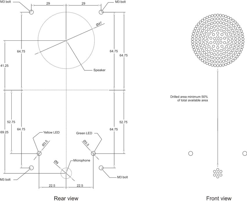
comply with Clause 5.2.1.6 of EN81-20:2014 and Clause 4.2.3 of EN81-28:2017.DRILLING PATTERN FOR COP
Fig 7
Speaker
LED LED
mic
DAU MM791 V02_EP_30/05/2018
Avire Ltd
Unit 1, The Switchback T: 01628 540100
Gardner Road
F: 01628 621 947
Maidenhead
Berkshire E: sales.uk@avire-global.com
Memco is a brand of Avire W: www.avire-global.com
SL6 7RJ, UKDigitales Audiomodul
Installationsanleitung
Version 2
MC-DAB00-100-F-C8-000
MC-DAB00-100-F-08-000
MC-DAB00-100-F-48-000
MC-DAP01-100-F-00-000
Digitales Audiomodul Variante für die SchachtgrubeDas digitale Audiomodul wird mit der digitalen Kommunikationsplattform verbunden und
bildet mit dieser einen 2-Wege-Kommunikationspunkt in der Fahrkabine. Das Gerät wird
hinter dem Bedienfeld montiert und über einen 4-adrigen digitalen CAN-Bus mit der
im Maschinenraum installierten digitalen Kommunikationsplattform verbunden. Diese
Verbindung bietet eine stabile Kommunikation über Schleppkabel bis zu 400m Länge.
Wir empfehlen unseren Kunden die Verwendung einer abgeschirmten, verdrillten
Zweidrahtleitung um. Störgeräusche im Sprachkanal, verursacht durch elektrisches
Rauschen in der Umgebung, vorzubeugen.
Abb 1
AUDIO-ERWEITERUNG
INDUKTIONSSCHLEIFE
STROMVERSORGUNG + (*)
STROMVERSORGUNG - (*)
STROMVERSORGUNG + (*)
STROMVERSORGUNG + (*) KABINEN-BUS CAN2 L
CAN1 L - DCP KABINEN-BUS CAN2 H
STROMVERSORGUNG - (*)
CAN1 H - DCP
STROMVERSORGUNG - (*)
KNOPF ALARMENDE
LOKALER PROGRAMMIER- ALARM-FILTER
ANSCHLUSS WARTUNGS-ALARMKNOPF
ALARMKNOPF KABINE
RS485-ANSCHLUSS COMMON
EXTERNE GELBE LED
OPTIONS-AUSWAHL EXTERNE GRÜNE LED
GEMEINSAME EXTERNE LEDs
Abb 2
Stromversorgung + Eingang optionale Induktionsschleife 2-adriger Anschluss für
Stromversorgung - Stromversorgung 8-28VDC MC-AAT00-100-0-08-000
250mA max. CAN 2 CAN-Bus-Anschluss nur für:
CAN 1 4-adriger Anschluss vom MC-DAB-00-F-28-000
DCP/CAN-Splitter. Strom- Alarmende Eingang für Alarmende-Signal
versorgung nicht nötig, wenn Alarmfilter Eingang für Alarmfilter
obige angeschlossen. H und L
Wartungsalarm Alarmknopf - ausschließlich frei
als Twisted Pair (empfohlen).
Kabinenalarm von Spannung. Sollte Spannun
Lokaler Nur für Debugging benötigt. aufdem Alarmknopf liegen, so ist
Programmier- (Kontaktieren Sie den ein Relais zu nutzen.
Anschluss technischen Support von
Common Gemeinsamer Common
Avire)
Piktogramm 1: Gelb Anschlüsse für externe
Optionen Siehe Abb. 3
Piktogramm 2: Grün Piktogramme
Audio-Erweiterung Ethernet-Kabelanschluss
Gemeinsamer
für externe Module; z.
Common
B. Triphony-Einheit,
Induktionsschleife usw.OPTIONSAUSWAHL (SW1)
Abb 3
OPTIONSAUSWAHL (SW1) FUNKTION BESCHREIBUNG
1 In einem System mit mehreren Fahrkabinen benötigt jedes
CAN1 ID digitale Audiomodul eine eindeutige ID (CAN1 ID); Abb. 4
2 zeigt, wie die ID eingestellt wird.
Aktiviert den CAN-Abschlusswiderstand für den CAN
3 CAN 2 Ω
2-Anschluss.
Aktiviert den CAN-Abschlusswiderstand für den CAN
4 CAN 1 Ω
1-Anschluss.
Hier kann das eingebaute Mikrofon ein- und ausgeschaltet
5 Mikrofon werden. Benötigt, wenn ein externes Mikrofons
angeschlossen ist.
Hier kann der eingebaute Lautsprecher ein- und
6 Lautsprecher ausgeschaltet werden. Benötigt, wenn ein externer
Lautsprecher angeschlossen ist.
1 2 3 4
1 CAN1
2 ID Abb 4
LED-ANZEIGEN
Das digitale Audiomodul hat zwei LEDs; grün und gelb. In der folgenden Tabelle sind
die Funktionen beschrieben:
Abb 5
Grüne LED Gelbe LED FUNKTION
AUS AUS Gerät auf Standby
Langsames Blinken AUS Anruf wird aufgebaut
Schnelles Blinken AUS Eingehender Anruf
AUS AN Alarm ausgelöst, Warten auf Rufannahme
AN AUS Fernkommunikation eingerichtet
AUS Langsames Blinken Alarm angenommen, Warten auf HilfeKONFIGURATIONSVERFAHREN
Das DAU wird über die Digitale Kommunikationsplattform (DCP) konfiguriert.
1) DER AVIRE HUB
Sobald ein digitaler Anschluss hergestellt worden ist, können alle Einstellungen extern
über den AvireHub konfiguriert werden. Bitte setzen Sie sich mit dem technischen
Support in Verbindung, wenn Sie weitere Informationen einschließlich einer
vollständigen Liste von Parametern und Systembefehlen benötigen.
2) SMS-BEFEHLE
Die meisten DCP-Parameter können per SMS extern konfiguriert werden. Jede SMS-
Nachricht muss mit dem Wort „PIN“ beginnen, dem die Konfigurationsbefehle folgen.
Sie können in jeder SMS verschiedene Parameter ändern oder überprüfen, indem
Sie diese mit Kommas „,“ trennen. Um einen Parameter abzurufen, fügen Sie ein
Fragezeichen „?“ hinzu.
An die DCP gesendete Beispiel-SMS, um die Alarmnummern 1 und 2 für alle
angeschlossenen CAN Bus-Audiomodule in „09876543210“ zu ändern und um die
aktuellen Alarmnummer 3 sowie die APN-Adresse der SIM-Karte zu prüfen:
Gesendet: PIN1234, P031 09876543210, P032 09876543210, P033?, P060?
Antwort: P031=09876543210 P032=09876543210 P033=01234567890 P060=wap.
vodafone.co.uk
Wenn die PIN falsch ist, sendet die DCP keine Antwort-SMS. Wenn die PIN korrekt ist,
sendet die DCP eine SMS mit der Meldung „ERROR“ oder „OK“.
3) LOKALE TELEFONKONFIGURATION
Um die Konfiguration über den lokalen Telefonmodus (wie zum
Beispiel Memco-Hörer) aufzurufen, müssen Sie den Hörer abnehmen
und, nachdem der Wählton zu hören ist, mit der Telefontastatur den
Zugangsbefehl für die Konfiguration eingeben. Für ein Gerät mit
PIN-Code 1234 wäre dieser Befehl:
*#*1234*#*
Um einen Parameterwert XX abzurufen, geben Sie mit der Tastatur *0XX* ein und der
Wert wird Ihnen vorgelesen. Um zum Beispiel Alarmnummer 1 für alle angeschlossenen
CAN Bus-Audiomodule zu hören, geben Sie *031* ein und die Nummer 09876543210
wird vorgelesen.
Um einen Parameterwert XX zu bearbeiten, geben Sie mit der Tastatur *0XX#N#,
wobei N der neue Wert ist. Um zum Beispiel Alarmnummer 2 zu aktualisieren, geben
Sie *032#01234567890# ein, und die Nummer wird in 01234567890 geändert. Nach
Eingabe der Aktualisierung antwortet das Gerät: „Option 0XX is N“.
Um die lokale Telefonkonfiguration abzuschließen, legen Sie den Hörer einfach
auf. Alternativ wird, wenn nach 30 Sekunden keine Aktivität festgestellt wird, die
Konfigurationssitzung automatisch beendet und Sie hören das Besetztzeichen.SPACHAUSWAHL
Bei Auslieferung des Moduls ist die voreingestellte Sprache im Standard Englisch. Bitte
befolgen Sie die nachfolgend aufgeführten Schritte, um die Spracheinstellung gemäß
Ihrem Wunsch anzupassen.
Tonwahltelefon:
Konfigurationsmodus:
Spracheinstellung aktualisieren: *085#X#
SMS: PIN1234,p085X
In den oben beschriebenen Befehlen steht ‘X’ für die jeweilige Sprache, die Sie in der
untenstehenden Liste finden können.
1 = Spanisch
2 = Portugiesisch
3 = Italienisch
4 = Englisch
5 = Deutsch
6 = Französisch
ARTIKELNUMMERN
Audioausgang für
CAN-Bus RS-485
Induktionsschleife
MC-DAB00-100-F-C8-000 ü û ü
MC-DAB00-100-F-08-000 û û ü
MC-DAB00-100-F-48-000 û ü ü
MC-DAP01-100-F-00-000 û û û Abb 6
MC-DAP01-100-F-00-000 = Variante, die in der Schachtgrube angebracht werden kann
und konform den Klauseln 5.2.1.6 der EN81-20:2014 sowie 4.2.3 der EN81-28:2017 ist.BOHRSCHABLONE FÜR BEDIENFELD
M3 Bolzen M3 Bolzen
Lautsprecher
Lautsprecher
die Bohrfläche muss mindestens
50% der kompletten Fläche
(47mm) sein.
gelbe LED grüne LED
LED LED
Mikrofon
mic
Rückansicht Frontansicht
Abb 7
DAU IG (DE) V02_EP_05/06/2018
T: +49 (0) 9721 38656-0
Avire Ltd T: +49 (0) 9721 38656-30
Am Zeughaus 9-13 F: +49 9721 38656-99
97421 Schweinfurt E: sales.de@avire-global.com
W: www.avire-global.com
Deutschland
Memco is a brand of AvireUnité Audio Numérique
Guide d’Installation
Version 2
MC-DAB00-100-F-C8-000
MC-DAB00-100-F-08-000
MC-DAB00-100-F-48-000
MC-DAP01-100-F-00-000
Unité Audio Numérique Variante Fond de fosseL’Unité Audio Numérique se connecte à la Plateforme de Communication Numérique
pour offrir un point de communication bidirectionnelle dans la cabine de l’ascenseur.
L’unité est montée derrière le panneau de commande de la cabine (COP) et se
connecte à la Plateforme de Communication Numérique de la salle des machines par
Bus CAN numérique à 4 fils. Cette connexion permet une communication stable jusqu’à
400m.
Entrée boutton d’alarme - libre de potentiel seulement. Si une tension est appliquée
sur le boutton, alors ajoutez un relai.
Fig 1
EXTENSION AUDIO
BOUCLE INDUCTIVE
ALIMENTATION + (*)
ALIMENTATION - (*)
ALIMENTATION + (*)
ALIMENTATION + (*) BUS CAN2 L DE LA CABINE
BUS CAN2 H DE LA CABINE
CAN1 L - DCP
ALIMENTATION - (*)
CAN1 H - DCP
ALIMENTATION - (*)
BOUTON FIN D’ALARME
CONNEXION LOCALE FILTRE ALARME
DE PROGRAMMATION BOUTON ALARME MAINTENANCE
BOUTON D’ALARME CABINE
CONNEXION RS485
TERRE
PICTOGRAMME JAUNE
SÉLECTION DES
OPTIONS PICTOGRAMME VERT
COMMUN
Fig 2
Alimentation + Entrée d’alimentation Connexion 2 fils vers
Boucle inductive
facultative 8-28VDC 250 mA MC-AAT00-100-0-08-000
Alimentation - max.
Connexion Bus CAN uniquement
Connexion 4 fils depuis CAN 2 sur :
Répartiteur DCP/CAN. MC-DAB-00-F-28-000
Alimentation non requise
Fin d’alarme Entrée du signal de fin d’alarme
CAN 1 si connecté au-dessus. Il
est recommandé que H et Filtre alarme Entrée du filtrage de l’alarme
L soit un câble simple paire
torsadée. Alm. maintenance Entrée boutton d’alarme - libre
de potentiel seulement. Si une
CONNEXION Uniquement requis pour
débogage. Alarme cabine tension est appliquée sur le
LOCALE DE
(Contactez le support boutton, alors ajoutez un relai.
PROGRAMMATION technique Avire)
Terre Terre
Options Voir fig. 3
Pictogramme 1 : Jaune
Connexion câble Ethernet Connexions pour pictogrammes
Pictogramme 2 : Vert
vers modules externes, par externes
Extension Audio
exemple unité triphonique, Commun partagé
boucle inductive, etc.SÉLECTEUR D’OPTIONS (SW1) Fig 3
SÉLECTEUR
D’OPTIONS FONCTION DESCRIPTION
(SW1)
1 Dans un système avec plus d’une cabine d’ascenseur, chaque Unité
CAN1 ID Audio Numérique a besoin d’une ID unique (CAN1 ID) ; voir la figure 4
2 pour régler l’ID.
3 CAN 2 Ω Active la résistance du terminal CAN pour le connecteur CAN 2
4 CAN 1 Ω Active la résistance du terminal CAN pour le connecteur CAN 1
Permet d’activer/désactiver le microphone intégré, à utiliser quand
5 Microphone
un microphone externe est connecté.
Permet d’activer/désactiver le haut-parleur intégré, à utiliser quand
6 Haut-parleur
un haut-parleur externe est connecté.
1 2 3 4
1 CAN1
2 ID Fig 4
INDICATEURS À LED
Il y a deux indicateurs à LED sur l’Unité : vert et jaune. Le tableau suivant décrit leur
fonctionnement.
Fig 5
LED verte LED jaune FONCTION
ETEINTE ETEINTE Dispositif en attente
Clignote lentement ETEINTE Début d’appel
Clignote rapidement ETEINTE Appel entrant
Alarme lancée, en attente de réponse à
ETEINTE ALLUMEE
l’appel
ALLUMEE OFF Communication à distance établie
ETEINTE Clignote lentement Alarme acceptée, en attente des secoursMÉTHODES DE CONFIGURATION
La DAU peut être configurée via la plateforme de communication numérique (DCP).
1) HUB AVIRE
Tous les paramètres peuvent être configurés à distance via le AvireHub une fois
la connexion numérique établie. Contactez l'assistance technique pour plus
d'informations ou pour obtenir la liste complète des paramètres et des commandes
du système.
2) COMMANDES SMS
La plupart des paramètres de la DCP peuvent être configurés à distance via SMS.
Chaque SMS doit comporter le mot « PIN » au début puis les commandes de
configuration. Vous pouvez modifier ou vérifier plusieurs paramètres dans un même
SMS en les séparant avec des virgules « , ». Pour consulter un paramètre, ajoutez un
point d'interrogation « ? ».
Exemple de SMS envoyé à la DCP pour mettre à jour les alarmes nº1 et 2 pour tous
les modules audio Bus CAN connectés au « 09876543210 », et pour vérifier le numéro
d’alarme no3 et l'adresse APN de la carte SIM :
Envoyé : PIN1234, P031 09876543210, P032 09876543210, P033?, P060?
Réponse : 031=09876543210 P032=09876543210 P033=01234567890 P060=wap.
P
vodafone.co.uk
Si le code PIN est incorrect, la DCP n'enverra pas de message de réponse. Si le code
PIN est correct, la DCP enverra un SMS indiquant « ERREUR » ou « OK ».
3) CONFIGURATION VIA TÉLÉPHONE LOCAL
Pour accéder à la configuration via téléphone local (tel que le
combiné MM), décrochez le combiné et, lorsque vous entendez
la tonalité, entrez la commande d'accès pour la configuration
à l'aide des touches du téléphone. Pour un appareil dont le code
PIN est 1234, cette commande est :
*#*1234*#*
Pour consulter une valeur du paramètre XX, utilisez les touches pour entrer *0XX* et la
valeur sera lue. Par exemple, pour entendre l'alarme nº1 pour tous les modules audio
Bus CAN connectés, tapez *031* et le numéro 09876543210 sera lu.
Pour modifier une valeur du paramètre XX, utilisez les touches pour entrer *0XX#N#,
N étant la nouvelle valeur. Par exemple, pour mettre à jour l'alarme nº2,
tapez *032#01234567890# et le nombre sera mis à jour au 01234567890. Une fois
que vous avez effectué la mise à jour, l'appareil répondra : « L'option 0XX est N ».
Pour terminer la configuration, raccrochez le téléphone. Sinon, si aucune activité
n'est détectée pendant 30 secondes, la session de configuration se terminera
automatiquement et le téléphone sonnera occupé.LANGUE
Les unités sont expédiées par défaut en anglais. Pour changer la langue, merci de
suivre ces étapes :
Téléphone à touche :
Entrer en mode configuration :
Mettre à jour le paramettrage de langue : *085#X#
SMS : PIN1234,p085X
Dans la commande ci-dessus, ‘X’ correspond au paramettre de langue de la liste ci-
dessous :
1 = Espagnol
2 = Portugais
3 = Italien
4 = Anglais
5 = Allemand
6 = Français
RÉFÉRENCES Fig 6
Sortie audio pour boucle
Bus CAN RS-485
inductive
MC-DAB00-100-F-C8-000 ü û ü
MC-DAB00-100-F-08-000 û û ü
MC-DAB00-100-F-48-000 û ü ü
MC-DAP01-100-F-00-000 û û û
MC-DAP01-100-F-00-000 = Variante pouvant être installée en fond de fosse afin d’être
conforme avec la clause 5.2.1.6 de la norme EN81-20:2014 et la clause 4.2.3 de la norme
EN81-28:2017PATRON DE PERÇAGE POUR LE COP Fig 7
Haut-parleur
Haut-parleur
Perforation représentant 50% minimum
de la surface du haut-parleur
LED Jaune LED Verte
LED LED
Microphone
Microphone
M3 Diamètre
M3 Diamètre
Vue arrière Vue de face
DAU IG (FR) V02_EP_04/06/2018
Avire Ltd
Tél. : (+33) 01 30 28 95 39
ZAC Des Portes de l’Oise Fax : (+33) 01 30 28 24 66
9 BIS Rue Léonard de Vinci E-mail : sales.fr@avire-global.com
60230 CHAMBLY Site : www.avire-global.com
France
Memco is a brand of AvireUnità Audio Digitale
Guida all’installazione
Version 2
MC-DAB00-100-F-C8-000
MC-DAB00-100-F-08-000
MC-DAB00-100-F-48-000
MC-DAP01-100-F-00-000
Unità Audio Digitale Variante per FOSSAL’Unità Audio Digitale si collega alla Piattaforma di comunicazione digitale per fornire un
punto di comunicazione a due vie nell’ascensore. L’Unità è montata dietro il pannello
di controllo cabina (COP) ed è collegata alla Piattaforma montata nella sala macchine
tramite bus CAN a quattro conduttori. Questo collegamento assicura comunicazioni
stabili su lunghezze dei cavi fino a 400 metri.
Si raccomanda ai clienti di utilizzare un cavo twisted pair schermato per garantire il
minimo disturbo al canale audio.
Fig 1
ESPANSIONE AUDIO
SISTEMA DI RILEVAMENTO/
ALIMENTAZIONE + (*) COMUNICAZIONE
ALIMENTAZIONE - (*)
ALIMENTAZIONE + (*)
ALIMENTAZIONE + (*) BUS CAN 2 L IN CABINA
CAN1 L - DCP BUS CAN 2 H IN CABINA
CAN1 H - DCP ALIMENTAZIONE - (*)
ALIMENTAZIONE - (*)
PULSANTE DI FINE ALLARME
COLLEGAMENTO LOCALE FILTRO ALLARME
PER PROGRAMMAZIONE PULSANTE ALLARME MANUTENZIONE
PULSANTE ALLARME CABINA
CONNESSIONE RS-485
COMUNE
LED ESTERNO GIALLO
SELEZIONE OPZIONI LED ESTERNO VERDE
LED ESTERNI COMUNI
Fig 2
Alimentazione + Ingresso alimentazione Collegamento a due conduttori
opzionale a 8 - 28 V CC, max. Anello ind. verso
Alimentazione - 250 mA MC-AAT00-100-0-08-000
Collegamento a quattro Collegamento bus CAN solo su:
CAN 2
conduttori da splitter DCP/ MC-DAB-00-F-28-000
CAN Se collegato, non
CAN 1 Fine dell’allarme Ingresso segnale fine allarme
necessita alimentazione Si
consiglia doppino ritorto per Filtro allarme Ingresso filtraggio allarme
H e L.
Allarme manutenzione Ingressi pulsante allarme - solo
Necessario soltanto per
Collegamento locale senza volt. Se c’è tensione sul
debugging.
per programmazione (Contatta l’assistenza tecnica Allarme cabina pulsante di allarme, aggiungere
Avire) il relè.
Opzioni Vedere Fig 3. Comune Comune condiviso
Collegamento cavo Ethernet Pittogramma 1: Giallo
Esp. audio verso moduli esterni; p.es. unità Collegamenti per pittogrammi
trifonia, anello induttivo ecc. Pittogramma 2: Verde
esterni
Comune condivisoSELETTORE OPZIONI (SW1)
Fig 3
SELETTORE
OPZIONI FUNZIONE DESCRIZIONE
(SW1)
1 In un impianto con più di un ascensore, è necessario un ID esclusivo
ID CAN 1 per ogni Unità Audio Digitale (ID CAN1); per impostare lo ID vedere
2 la figura 4.
3 CAN 2 Ω Attiva il resistore di terminazione CAN del connettore CAN 2
4 CAN 1 Ω Attiva il resistore di terminazione CAN del connettore CAN 1
Utilizzato per attivare/disattivare il microfono integrato; da utilizzare
5 Microfono
quando si collega un microfono esterno.
Utilizzato per attivare/disattivare l’altoparlante integrato; da utilizzare
6 Altoparlante
quando si collega un altoparlante esterno.
1 2 3 4
1 CAN1
2 ID
Fig 4
INDICATORI A LED
L’Unità Audio Digitale ha due indicatori a LED: Verde e Giallo, il cui funzionamento è
descritto nella tabella che segue.
Fig 5
LED Verde LED Giallo FUNZIONE
OFF OFF Dispositivo in stand-by
Lampeggio lento OFF Inizio chiamata
Lampeggio rapido OFF Chiamata entrante
OFF ON Attivato allarme, attesa accettazione chiamata
ON OFF Stabilita comunicazione remota
OFF Lampeggio lento Allarme accettato, attesa interventoMETODI DI CONFIGURAZIONE
La DAU sono configurate tramite la Piattaforma di Comunicazione Digitale (DCP)
1) AVIREHUB
Una volta stabilita una connessione digitale, tutte le impostazioni possono essere
configurate da remoto tramite AvireHub. Per ulteriori informazioni, incluso un elenco
completo di parametri e comandi di sistema, contattare il supporto tecnico.
2) COMANDI VIA SMS
La maggior parte dei parametri della DCP possono essere configurati da remoto
tramite SMS. Ciascun messaggio SMS deve iniziare con la parola “PIN” seguita dai
comandi di configurazione. È possibile modificare o controllare diversi parametri in
ogni SMS separandoli con virgole “,”. Per recuperare un parametro, aggiungere un punto
interrogativo “?”.
SMS d'esempio inviato alla DCP per aggiornare i numeri di allarme 1 e 2 per tutti
i moduli audio del bus CAN collegati a “09876543210” e per controllare il numero
di allarme 3 corrente e l'indirizzo APN della scheda SIM:
Inviato: PIN1234, P031 09876543210, P032 09876543210, P033?, P060?
Risposta: P
031=09876543210 P032=09876543210 P033=01234567890 P060=wap.
vodafone.co.uk
In caso di PIN errato, la DCP non invierà un SMS di risposta. In caso di PIN corretto,
la DCP invierà un SMS indicante “ERROR” o “OK”.
3) CONFIGURAZIONE DEL TELEFONO LOCALE
Per inserire una configurazione tramite la modalità telefono locale
(come un ricevitore MM), è necessario sollevare il ricevitore e, dopo
aver udito il segnale di linea, immettere il comando di configurazione
tramite il tastierino del telefono. Per un dispositivo con codice PIN
1234, questo comando è:
*#*1234*#*
Per recuperare un valore di parametro XX, utilizzare il tastierino per immettere *0XX*,
così da rileggere il valore. Ad esempio, per ascoltare il numero di allarme 1 per
tutti i moduli audio del bus CAN collegati, digitare *031* e verrà ripetuto il
numero 09876543210.
Per modificare un valore di parametro XX, utilizzare il tastierino per immettere
*0XX#N#, dove N è il nuovo valore. Ad esempio, per aggiornare il numero di allarme 2,
digitare *032#01234567890# e il numero verrà aggiornato a 01234567890. Dopo aver
immesso l'aggiornamento, il dispositivo risponderà: “L'opzione 0XX è N”.
Per completare la configurazione del telefono locale, è sufficiente agganciare
il ricevitore. In alternativa, in assenza di attività per 30 secondi, la sessione di
configurazione terminerà automaticamente e si udirà il segnale d'occupato.OPZIONI LINGUA
Units are shipped as standard with the default language set to ENGLISH. To change the
language settings follow these steps:
Telefono a toni:
Entrare nella modalita’ di configurazione:
Aggiornare le impostazioni di lingua con il parametro: *085#X#
SMS: PIN1234,p085X
Nei comandi precedenti, “X” è l’impostazione della lingua scelta dal seguente elenco:
1 = Spagnolo
2 = Portoghese
3 = Italiano
4 = Inglese
5 = Tedesco
6 = Francese
CODICI PRODOTTO
Uscita audio per sistema di
Bus CAN RS-485
rilevamento/comunicazione
MC-DAB00-100-F-C8-000 ü û ü
MC-DAB00-100-F-08-000 û û ü
MC-DAB00-100-F-48-000 û ü ü
MC-DAP01-100-F-00-000 û û û Fig 6
MC-DAP01-100-F-00-000 = variante che puo’ essere installata nella fossa in conformita’
ai punti 5.2.1.6 del EN81-20:2014 e 4.2.3 del EN81-28:2017.MASCHERA DI FORATURA SU COP
Speaker
LED LED
mic
Fig 7
DAU IG (IT) V02_EP_05/06/2018
Avire Ltd
Via G. B. Pergolesi 8, T: +39 0276014334
20124 Milano F: +39 3355994156
Italia E: sales.it@avire-global.com
W: www.avire-global.com
Memco is a brand of AvireSie können auch lesen