Flow-Measurement Technology Durchfluss-Messtechnik
←
→
Transkription von Seiteninhalten
Wenn Ihr Browser die Seite nicht korrekt rendert, bitte, lesen Sie den Inhalt der Seite unten
Flow-
                     Measurement
                          Technology   Durchfluss
                                       -Messtechnik

VS series                                  Serie VS
Flow measurement                           Messtechnik
Precision dosing                           Dosiertechnik
Hydraulic systems                          Hydraulik
Systems monitoring                         Überwachungstechnik
Open/closed                                Steuer- und
loop control                               Regeltechnik
Process control                            Verfahrenstechnik

                                                                 1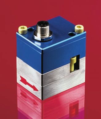
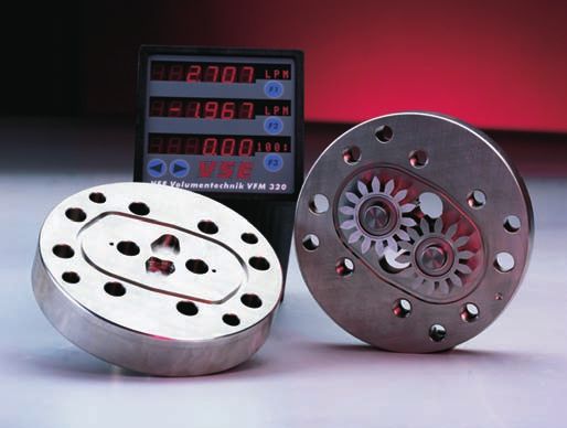
VS – Volumensensoren

        VS-Volumensensoren messen den             soren bestehen aus zwei Differential-        angeordnet. Für Medientemperaturen
    Volumenstrom      von    Flüssigkeiten        Feldplatten, die um eine viertel Zahn-       bis zu 210°C steht ein spezielles
    nach dem Zahnradprinzip. Ein im               teilung zueinander versetzt angeordnet       Aufnehmersystem zur Verfügung.
    Gehäuse sehr präzise eingepasstes             sind. Die Signale der beiden Aufneh-         Technische Daten auf Seite 13 und 14.
    Zahnradpaar bildet das Messwerk. Die          mersensoren werden mit zwei Signal-
    Messwerksdrehung wird zahnweise von           verstärkern digitalisiert und durch nach-        VS-Volumensensoren sind für Versor-
    einem Signalaufnehmer-System berüh-           geschaltete kurzschlussfeste Gegentakt-      gungsspannungen von 12V DC oder
    rungslos erfasst; jeder Zahn erzeugt          endstufen verstärkt. Die Rechteck-Aus-       24V DC lieferbar. Spezielle Ex-Schutz-
    einen Impuls.                                 gangssignale sind bidirektional und          Ausführungen ermöglichen den Einsatz
                                                  können von allen elektronischen Aus-         in explosionsgefährdeten Bereichen.
        Die Zahnlücken der Messwerksräder         wertegeräten, SPS-Steuerungen und            Diese Typen haben die EX-Zulassung
    bilden in den Bereichen, in denen sie         Computern problemlos verarbeitet wer-            II 1G EEx ia IIC T6 und werden mit
    von den Gehäusewänden vollständig             den. Aus den um 90° versetzten Sig-          Sicherheitsbarrieren in der Schutzart
    umschlossen sind, Messwerkskammern,           nalen ist durch entsprechende Auswer-        „Eigensicherheit“ betrieben (siehe auch
    die den Flüssigkeitsstrom in Abhängigkeit     tung die Durchflussrichtung zu erkennen      Seite 11, 12 und 18).
    ihrer Kammervolumen digitalisieren.           und eine Impulsauswertung mit Faktor
                                                  1, 2 und 4 möglich.                              Volumensensor-Auswahl
        Die innerhalb einer Messwerks-                                                         Für einen störungsfreien und sicheren
    drehung um eine Zahnteilung durch-                 Die Frequenz der Signale ist pro-       Betrieb der Volumensensoren ist die rich-
    gesetzte Flüssigkeitsmenge bildet das         portional zum momentanen Durchfluss          tige Auswahl (Auslegung) von Typ und
    Messvolumen pro Impuls (Vm) und ist           (Volumenstrom) und abhängig von der          Baugröße entscheidend. Aufgrund der
    in cm3/Imp. definiert. Es kennzeichnet        jeweiligen Volumensensor-Baugröße.           Vielzahl verschiedener Anwendungen
    zugleich die Baugröße eines Volumen-          Der Frequenzbereich erstreckt sich von       und     Volumensensor-Ausführungen
    sensors.                                      0 – 2000 Hz. Der Vorverstärker ist           sind die technischen Daten im VSE-
                                                  gegen Verpolung und falsches An-             Katalogmaterial allgemeiner Art.
        Erläuterungen zum Vorver-                 schließen geschützt. Er ist bei Medien-      Bestimmte Eigenschaften der Geräte
        stärker vom Signalaufnehmer-              temperaturen von –30 ... 100°C direkt        sind abhängig von Typ, Baugröße und
        System (Seite 3)                          am Deckel des Volumensensors mon-            Messbereich sowie von der zu messen-
                                                  tiert, bei Medientemperaturen von 100        den Flüssigkeit. Für eine exakte Aus-
        Die berührungslosen Aufnehmersen-         ... 150°C wird er von diesem getrennt        legung kontaktieren Sie bitte VSE.

VS Positive Displacement Flowmeters
        VS positive displacement flowme-             Explanations to preamplifier              cover whereas between temperatures
    ters are volume rate measuring sensors           of Signal pick-up System (page 3)         of 100°C and 150°C (212°F and 302°F)
    based on the meshing gear principle                                                        the preamplifier is positioned remotely.
    and are designed for use with liquids.             The non-contact pick-up sensors con-    For medium temperatures up to 210°C
    Two precisely matched gear wheels are         sist of two differential magneto resistors   (410°F) a special pick up system is avai-
    enclosed in a very accurately machined        which are circumferentially offset from      lable. Technical data on page 13 and 14.
    housing. Gear rotation is sensed by a         one another by 1/4 of a tooth pitch.
    non-contacting signal pick-up system.         The signals of both pick-up sensors are          VS positive displacement flowmeters
    Each tooth produces one impulse.              digitized with two signal amplifiers and     are available for supply voltages of
                                                  amplified via followed short-circuit proof   12V DC or 24V DC. Intrinsically safe
        The space between the gear teeth,         push-pull output stages. The square          models, with approval code         II 1G
    when fully enclosed on both sides by          wave output signals are bi-directional       EEx ia IIC T6, are supplied for applicati-
    the housing, constitute measuring cham-       and may be simply processed by any           ons in potentially hazardous areas. VSE
    bers. Fluid flow causes the gears to rotate   external electronics, plc control or com-    also supplies the required sets of safety
    and the incoming flow is separated into       puter. The processing of the 90° phase       barriers (see page 11,12 and 18).
    discrete volumes within these cham-           angle between signals enables recogni-
    bers i. e. the volume of liquid passing       tion of flow direction and impulse rate          Flowmeter Selection
    through the unit will cause rotation of       conversion with a factor of 1, 2 and 4.      For trouble-free and safe operation of
    the gears by exactly one tooth pitch.                                                      the flowmeters the correct selection of
                                                      The signal frequency is proportio-       type and size is decisive. Due to the
         This volume is known as the Volume/      nal to the momentary flow rate (volu-        great number of different applications
    Impulse (Vm) and is stated in cc/Imp. It      me rate) dependent on the particular         and flowmeter versions, the technical
    is used to define the size of a flowme-       flowmeter size. The frequency range          data in the VSE-catalogues are of
    ter.                                          extends from 0 – 2000 Hz. The pre-           general character. Certain characte-
                                                  amplifier is protected against reverse       ristics of the devices depend on type,
                                                  polarity and incorrect connection. For       size and measuring range as well as
                                                  medium temperatures between –30°C            on the medium to be measured. For
                                                  and 100°C (–22°F and 212°F) the unit         exact flowmeter choice please contact
                                                  is mounted directly on the flowmeter         VSE.

2
Block Diagram                                                                                                     Blockschaltbild
Preamplifier of Signal Pick-up System                                                 Vorverstärker vom Signalaufnehmer-System

                                                                                                                                     + VOLT
                                                                                                                                     Supply
          Sensor 1
                                                                                                                                     + Volts
          Sensor 1

                                                                                                                                      Kanal 1
                                                                                                                                      Channel 1

                                                                                                                                      0 Volt
                                                                                                                                      Supply
                                                                                                                                      0 Volts

                                                                                                                                     Kanal 2
                                                                                                                                     Channel 2

          Sensor 2                      Signalverstärker                       Gegentaktendstufen
          Sensor 2                      Signal Amplifiers                      Push-pull output stages

Output Signals of Preamplifier                                                                        Ausgangssignale am Vorverstärker

                                      Messwerksdrehung um eine Teilung                                           Spannungsbereiche
                                      Gear rotation of one tooth pitch
                                      1 Impuls
                                                                                                              Versorgungsspannunng:
                                      One impulse                                                             UV = 10 - 16V; 20 - 28V DC
                                      Messvolumen/Impuls (Vm) in cm3/Imp                                      Signalspannung:
                                      Volume/impulse
                                      Volume/impulse 1 Vm (cm3/Imp)                                           Uss = UV - 1V

   Kanal 1
   Channel 1
                                                                                Uss Upp
                                                                                                                  Voltage Ranges
                                Kanalversatz um eine       Channel offset by
                                                           1/4 of tooth pitch (90°)
                                                                                                               Supply voltage:
                                Viertel
                                    tel TTeilung
                                          eilung (90°)
                                                                                                               UV = 10 - 16V; 20 - 28V DC
   Kanal 2                                                                                                     Impulse voltage:
   Channel 2                                                                                                   Upp = UV - 1V
                                Tastverhältnis
                                  stverhältnis eines Impulses
                                                     Impulse       Impulse mark/space ratio
                                (am Vorververstärker
                                            verstärker justiert)
                                                       justie      (adjust. at preamplifier)
                         1:1
                   Durchflussrichtung 1             Durchflussrichtung 2
                   Flow in direction 1              Flow in opposite direction 2

Plug Connection Diagram                                                                                                     Stecker-Anschlussbild

     Ansicht A                                         Kanal 1 (weiß)                                 Speisung + Volt (braun)
     View A                                            Channel 1 (white)              2          1     Supply + Volt (brown)
                                                       Speisung 0 Volt (blau)              3 4       Kanal 2 (schwarz)
                                                       Supply 0 Volts (blue)                         Channel 2 (black)

     Verkabelung des Volumensensor auf die Auswert-Elektronik                                                    Änderung der Durchflussrichtungs-
     Cable connection flowmeter to pulse processor                                                               anzeige (+ nach -/- nach +) durch
                                                                                                                 Vertauschen der Kanäle
                                                                                                                 (Kanal 1        Kanal 2)
               1      + Volt (braun)           + Volts (brown)                        +
               2      Kanal 1 (weiß)           Channel 1 (white)                      K1
                                                                                            Elektronik-          To change the flow direction sign
                                                                                           Auswertung            (+ to -/- to +) interchange the
               3      0 Volt (blau)            0 Volts (blue)                         0V
               4      Kanal 2 (schwarz)        Channel 2 (black)                              Pulse-             channel connection
                                                                                      K2    Processor            (Channel 1            Channel 2)
                                                                                      0V

                                                                                                                                                     3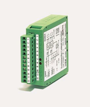
Applications                                                   Anwendungsgebiete

        All liquids that can be pumped and            Es können alle Füssigkeiten gemes-
    have known lubrication properties can        sen werden, die pumpfähig sind und eine
    be measured, for example: Petrol, para-      gewisse Schmierfähigkeit haben, wie
    fin, kerosene, diesel; Skydrol, mineral      z. B.: Petroleum, Benzine, Dieselöl (Ke-
    oils, hydraulic oils including fire resis-   rosin); Skydrol, Mineralöle, Hydraulik-
    tant fluids; inks, dyes and paints; grea-    öle (auch schwerentflammbare); Farben;
    ses; polyurethane, polyol and isocyana-      Fette; Polyurethan, Polyol, Isocyanat;
    tes; Araldite; glues, pastes and creams;     Araldite; Kleber; Pasten; Harze; Wachs
    resins; waxes … and many others.             u. a.

Ranges of Use Include                                            Einsatzgebiete z. B.

       Automobile industry                          Automobilindustrie
       Braking system test stands                   Bremsenprüfstände
       Fuel consumption measurement                 Verbrauchsmessungen von
                                                    Kraftstoffen
       Polyurethane foams for steering              Polyurethan-Schäume für Lenkräder,
       wheels, fascia, seats etc.                   Verblendungen, Sitze etc.
       Paint spraying systems                       Farbspritzanlagen
       Steering systems                             Lenksysteme
       Batching and filling of motor oils,          Dosieren und Abfüllen von Motor-
       brake fluids, anti-freeze, rust pre-         ölen, Bremsflüssigkeiten, Frostschutz-
       ventatives, waxes etc.                       mitteln, Konservierungsstoffen,
                                                    Wachsen etc.
       Adhesive coatings for windscreens,           Kleberauftrag auf Windschutzschei-
       headlights, engine housings etc.             ben, Scheinwerfern, Motorgehäusen
                                                    etc.

       Hydraulic                                    Hydraulik
       Volume and flow rate measurement             Volumen- und Durchflussmessung
       Leakage and rupture monitoring               Leck- und Bruchüberwachung
       Cylinder speed and position measu-           Zylinderweg- und Geschwindig-
       rement                                       keitsmessung
       Positioning and step control                 Positionierung und Schrittsteuerungen
       Measurement, control and regulation          Messen, Steuern, Regeln von Durch-
       of flow rates and volumes                    flüssen und Volumina
       Test beds for pumps, motors, valves,         Prüfstände für Pumpen, Motoren,
       proportionals and servo-valves               Ventile, Proportional- und
                                                    Servoventile
       Synchronised multi-cylinder                  Mehrfach-Zylinder Gleichlauf-
       monitoring                                   steuerungen
       Filling and additive blending                Abfüllen und Dosieren

       Dyes and paints                              Farben und Lacke
       Paint spraying systems                       Farbsprizanlagen
       Batching and filling                         Dosieren und Abfüllen
       Volume, flow rate and consumption            Mengen-, Durchfluss- und
       measurement                                  Verbrauchsmessungen
       Monitoring of mixing ratios                  Mischverhältnisse überwachen

4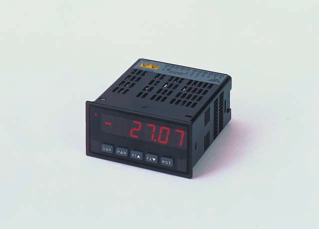
Ranges of Use Include                                                    Einsatzgebiete z. B.

      Plastics technology                                Kunststofftechnik allgemein
      Mixing, moulding and batching                      Misch-, Gieß- und Dosieranlagen
      systems for single and multicompo-                 von ein- bzw. mehrkomponentigen
      nent fluid plastics                                Flüssigkeitsstoffen
      Consumption measurement of                         Verbrauchsmessungen
      for example:                                       von z. B.:
      Epoxy adhesives and potting com-                   Exposit-Klebern und Vergussmassen
      pounds (resins and hardeners) for                  (Harz und Härter) für Transforma-
      transformers, coils, relays, conden-               toren, Spulen, Relais, Kondensa-
      sers, armatures, initiators, auto-elec-            toren, Motorankern, Initiatioren,
                                                         Automobilelektronik etc.
      tronics
                                                         Messen, Steuern und Regeln einzel-
      Measuring, control and regulation
                                                         ner Komponenten und Mischungs-
      of single components and mixing
                                                         verhältnisse
      ratios
                                                         Silikon-Vergussmassen
      Silicon potting compounds
                                                         Durchfluss- und Volumenmessungen
      Flow rate and volume measurement
                                                         Polyurethan-Schäume (Polyol und
      Polyurethane foams (polyol and iso-
                                                         Isocyanat) für Lenkräder,
      cyanate) for steering wheels, seals,               Dichtungen, Schuhe, Schuhsohlen,
      shoes, soles, surf boards, furniture,              Surfbretter, Möbel, PC-Gehäuse,
      computer casings, isolation etc.                   Isolierungen, etc.

      Chemical industry
                                                         Chemische Industrie
      Flow rate and volume measurement
                                                         Durchfluss- und Volumenmessung in
      in process plant and plant systems
                                                         Verfahrenstechnischen Anlagen und
                                                         Anlagensystemen
      Blending and filling chemical pro-
                                                         Dosieren und Abfüllen chemischer
      ducts such as liquid plastics adhesi-
                                                         Produkte wie flüssige Kunststoffe,
      ves, resins, hardeners, potting, com-              Kleber, Härter, Harze, Vergussmas-
      pounds, solvents, fuels, foames plas-              sen, Lösungsmittel, Treibmittel,
      ticisers, dyes and paints, oils and                Schäume, Weichmacher, Farben
      synthetic products etc.                            und Lacke, Öle und synthetische
                                                         Produkte etc.
      Application in laboratories and                    Einsatz im Labor sowie in den
      manufacturing plants (in normal                    Fertigungsanlagen (in normalen
      and hazardous areas)                               wie in explosionsgefährdeten
                                                         Bereichen)
      Control and regulation of single                   Steuern und Regeln der einzelnen
      components, mixing ratios and con-                 Komponenten, des Mischungsver-
      sumption of various components                     hältnisses mehrerer Komponenten
                                                         und des Verbrauchs
      Leakage measurement and leakage                    Leckagemessung und Leckageüber-
      monitoring on plant                                wachung an Anlagen
      Measurement, indication and log-                   Messen, Anzeigen und Registrieren
      ging of data for product quality                   der Messwerte zum Qualitätsnach-
      assurance                                          weis der hergestellten Produkte

      Customer specific                                  Sonder- und Spezial-
      designs on request                                 ausführungen auf Anfrage

   The issue of this catalogue invalidates all spe-   Mit der Herausgabe dieses Kataloges
   cifications in earlier publications. Changes and   erlöschen sämtliche Angaben aus früheren
   deviations are reserved by VSE. VSE will not       Publikationen. Änderungen und Abweichungen
   accept liability for printing errors.              bleiben VSE vorbehalten. Für mögliche Druck-
   Reproduction, including excerpts, is only per-     fehler übernimmt VSE keine Haftung.
   mitted with written permission by VSE.             Vervielfältigung, auch Auszüge, sind nur nach
   Revision: 11/ 2005                                 schriftlicher Genehmigung durch VSE gestattet.
                                                      Stand 11/2005

                                                                                                       5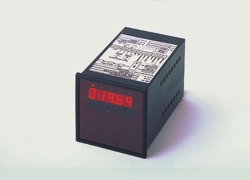
Technical Data – Overview                                                                                      Technische Daten – Übersicht

    Baugröße Messbereich*                      Flow Range*                  K-Faktor      K-Factor                  Umrechnungsfaktor
    Size           l/min                       GPM                          Imp./l        Imp./Gal.                Calculation Factor
    VS 0.02 0.002...........2                  0.0005............0.53        50 000 189 272                  1    litre      ^ 0.26417 U.S.Gallon
                                                                                                                             =
                                                                                                             1               ^ 3.78544 litre
                                                                                                                  U.S.Gallon =
    VS 0.04 0.004...........4                  0.0011............1.06        25 000       94 636
                                                                                                             1    bar        ^ 14.503684 psi
                                                                                                                             =
    VS 0.1       0.01...........10             0.0026............2.64        10 000       37 854.4
                                                                                                             1    psi        ^
                                                                                                                             = 0.068948 bar
    VS 0.2       0.02...........18             0.0053............4.76          5 000      18 927.2
    VS 0.4       0.03...........40             0.0079..........10.57           2 500        9 463.6          °C = 5 x (°F - 32)      psi   = pound-weight
                                                                                                                         9
                                                                                                                                             per square inch
    VS 1         0.05...........80             0.0132..........21.13           1 000        3 785.44
                                                                                                             °F =   9 x °C   +32
    VS 2         0.1...........150             0.0264..........39.63             500        1 892.72                  5
                                                                                                                                     GPM = U.S.Gallon
                                                                                                                                           per minute
    VS 4         1..............300            0.2642..........79.25             250          946.36
                   * bei 21 cSt                    * at 21 cSt

    Messgenauigkeit                          ± 0,3 % vom Messwert bei Viskosität > 20 cSt (< 20 cSt abnehmende Messgenauigkeit)
    Accuracy                                 ± 0.3 % of measured value at viscosity > 20 cSt (< 20 cSt reduced accuracy)
    Wiederholgenauigkeit                     ± 0,05 % unter gleichen Betriebsbedingungen
    Repeatability                            ± 0.05 % under same operating conditions
    Material                                 Gehäuse                        Messwerkslagerung                                          Dichtungen
                                             Grauguss GGG 40 oder           mediumbedingt als Kugellager                               FPM (Standard)
                                             Edelstahl 1.4305               oder Gleitlager (auch buntmetallfrei)                      NBR, PTFE, EPDM
    Materials                                Body                           Bearings                                                   Seals
                                             Cast Iron GGG 40 or            Ball / Plain / Plain (copper-free),                        FKM (Standard)
                                             Stainless Steel 1.4305         dependent on liquid                                        NBR, PTFE, EPDM
    Max. Betriebsdrücke                      Graugussgehäuse                315 bar/4568 psi Edelstahlgehäuse                     450 bar / 6 526 psi
    Max. Operating Pressures                 Cast Iron                      315 bar/4 568 psi Stainless Steel                     450 bar / 6 526 psi
    Mediumtemperatur                         -40°C...210°C mit HT Sensorsystem
    Medium Temperature                       -40 °C...210 °C (-40°F...410°F) with high temperature pick up system
    Viskositätsbereich                       1...100 000 cSt.
    Viscosity Range                          1...100 000 cSt.
    Einbaulage                               beliebig, über Anschlussplatte mit Anschluss seitlich oder von unten
    Mounting Positions                       unrestricted, on subplate with side or bottom connections
    Filtrierung                              VS 0.02/0.04/0.1             10 µm               Ausnahmen               Geräte mit speziell angepasster
    (für Kugellagerausführung)               VS 0.2/0.4                   20 µm                                       Messwerktoleranz
                                             VS 1/2                       50 µm                                       (auf Anfrage)
                                             VS 4                         50 µm
    Filtering                                VS 0.02/0.04/0.1             10 µm               Exceptions              flowmeter with special
    (for ball bearing type)                  VS 0.2/0.4                   20 µm                                       clearance (on request)
                                             VS 1/2                       50 µm
                                             VS 4                         50 µm
    Laufgeräusche                            max. 72 dB(A)
    Noise Level                              max. 72 dB(A)
    Vorverstärker                            kurzschlussfest und verpolungssicher
                                             Spannungs-            24 V DC/40 mA (20...28 V DC), zusätzlicher Strom am Signalausgang
                                             versorgung            max. 20 mA
                                                                   12 V DC/30 mA (10...16 V DC), zusätzlicher Strom am Signalausgang
                                                                   max. 10 mA
    Preamplifier                             short circuit proof and reverse polarity proof
                                             Power                 24 V DC/40 mA (20...28 V DC), additional current on signal output
                                             supply                max. 20 mA
                                                                   12 V DC/30 mA (10...16 V DC), additional current on signal output
                                                                   max. 10 mA
    Elektrischer Anschluss                   genormter Steckeranschluss mit 4-adrig abgeschirmter Leitung, Alternativ: 4-poliger Stecker
    Lieferbare VS                            Standard                      Stecker mit gelbem Kabel         2              5/10/15/20 m
    Anschlusskabel         1                 Für EX-Ausführung             Stecker mit blauem Kabel         2              5/10/15/20 m
    Electrical Connection                    standard 4-pin plug connection with 4-core shielded cable, Alternative: 4-pin plug
    Available VS                             Standard                      Plug with yellow cable           2              5/10/15/20 m
    connecting cable       1                 For Ex design                 Plug with blue cable             2              5/10/15/20 m

                              1 Die Anschlusskabel sind am zweiten Ende offen, können jedoch auf Wunsch mit einem zweiten Stecker geliefert werden.
                                The connecting cables are open at one end, but can be delivered with a second plug on request.
6                             2 Andere Kabellängen auf Anfrage. Other cable lenghts on request.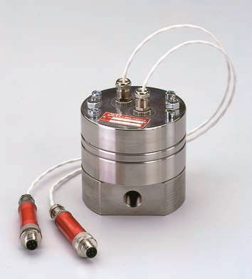
Durchflusswiderstand Δ p                         Durchflusswiderstand Δ p                           Durchflusswiderstand Δ p                           Durchflusswiderstand Δ p
                   Flow resistance Δ p                              Flow resistance Δ p                                Flow resistance Δ p                                Flow resistance Δ p

                                              VS 2
                                                                                               VS 0.4
                                                                                                                                                  VS 0.1
                                                                                                                                                                                                     VS 0.02

    Durchfluss Q
                                                     Durchfluss Q
                                                                                                        Durchfluss Q
                                                                                                                                                           Durchfluss Q
                                                                                                                                                                                                                Flow Response Curves

    Flow rate Q
                                                     Flow rate Q
                                                                                                        Flow rate Q
                                                                                                                                                           Flow rate Q

                   Durchflusswiderstand Δ p                         Durchflusswiderstand Δ p                           Durchflusswiderstand Δ p                           Durchflusswiderstand Δ p
                   Flow resistance Δ p                              Flow resistance Δ p                                Flow resistance Δ p                                Flow resistance Δ p

                                                                                               VS 1

                                              VS 4
                                                                                                                                                  VS 0.2
                                                                                                                                                                                                     VS 0.04

    Durchfluss Q
                                                     Durchfluss Q
                                                                                                        Durchfluss Q
                                                                                                                                                           Durchfluss Q

    Flow rate Q
                                                     Flow rate Q
                                                                                                        Flow rate Q
                                                                                                                                                           Flow rate Q
                                                                                                                                                                                                               VS-Durchflusskennlinien

7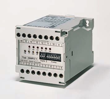
VS Flow Meter Dimensions                                                           Abmessungen Volumensensoren VS

         Graugussausführung                                                                O-Ring
         Gehäuse mit Fräskante
         Cast iron version
         Housing curve mill cutted

                                                                                                          M
                                                                                                     N
                                 Steckerposition für VS1/VS2,
                                 Steckerposition für andere
                                 VS-Typen: +90° im Uhrzeigersinn
                                                                                                          Graugussausführung
                                 Plug direction for VS1/VS2,                                              Anschlussbild
                                 Plug direction for the other                         L                   Ansicht X
    Zentrierbohrung              VS-types: +90° clockwise                                                 Cast iron version
      Centre bores                                                                                        Connection drawing
                                                                                                          View X
                        M 12x1
                                                                                                         Edelstahlausführung
                                                                                                         Anschlussbild
                                                                                                         Gehäuse ohne Fräskante

                                                                    H
    B

                                                                C                                        Ansicht X
                                                  øG
                                                           K

                                                                                                          Stainless steel version
                    A                                                                 A                   Connection drawing
                                                   D                                                      Housing not mill cutted
                                                           E

                                              X
                                                                                                          View X

                                                                                                                       Gewicht Weight

        Baugröße         A     B      C      D         E   ø G      H    K     L      M      N       O-Ring              GG      E
        Size                                                                                                             kg     kg
        VS 0.02         100    80    91    M 6     12.5 ø       9 114   58    70      40     20      11 x 2              2.8    3.4
        VS 0.04         100    80    92    M 6     11.5 ø       9 115   59    70      40     20      11 x 2              2.8    3.4
        VS 0.1          100    80    94    M 6         9   ø    9 117   61    70      40     20      11 x 2              2.8    3.4
        VS 0.2          100    80    94    M 6         9   ø    9 117   61    70      40     20      11 x 2              3.0    3.7
        VS 0.4          115    90    96.5 M 8      16.5 ø 16 120        63.5 80       38     34      18 x 2.62           4.0    5.0
        VS 1            130   100 101      M 8     12      ø 16 124     68    84      72     34      18 x 2.62           5.3    6.8
        VS 2            130   100 118      M 8     15      ø 16 141     85    84      72     34      18 x 2.62           6.7    8.4
        VS 4            180   140 145      M 12    20      ø 30 168     110   46      95     45      36.17 x 2.62      14.7 18.4

         GG = Grauguss GGG 40                       GG     = Cast iron GGG 40
         E    = Edelstahl 1.4305                    E      = Stainless Steel 1.4305
         Die Abmessungen sind in mm                 Dimensions are specified in mm
         angegeben.                                 1 mm = ^ 0.03937 inch
                                                           ^ 25.4 mm
                                                    1 inch =

    Volumensensor
    Flowmeter                                                                                            Volumensensor
                                                                                                         Flowmeter

    Anschlussplatte
    Subplate
                                                                                                         Anschlussplatte
                                                                                                         Subplate
    Anschlusslage seitlich
    Side ports                                                                                   Anschlusslage unten
                                                                                                 Bottom ports

8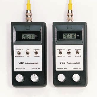
AP Subplate Dimensions                                                                           Abmessungen Anschlussplatten AP

   Anschlusslage seitlich               Side ports                          Anschlusslage unten          *         Bottom ports        *
   Grauguss         APG . S.../.        Edelstahl          APE . S.../.     Grauguss             APG . U.../.      Edelstahl               APE . U.../.
   Cast iron                            Stainless steel                     Cast iron                              Stainless steel

            A                                    A                                      A

                                                C                                       C                                      C
            C

                                                                                                     D
                                                                                                             B

                                                                                                                                                D
                                                                                                                                                    L
                                                               D
                         D
                             B

                                                                   L
                                                                                        E                                      E

                                                                                                       F

                                                                                                                                                 F
                           øH

                                                               G
                      G

                            F

                                                                    F
                                                                                     M                                 M
           M                                    M
                                                                                             G                                     G

   * Beide Anschlüsse (G) der Baugrößen APG 4 U und APE 4 U sind im Vergleich zu den abgebildeten Zeichnungen
    um 90° versetzt.
   * Both bottom ports (G) for size APG 4 U and APE 4 U have a displacement of 90° to the shown drawings.

   Zug. Baugröße     G-Rohrgewindezuordnung                         Baugröße          Baugröße                                         Tiefe    Gewicht
   Affilated Size    G pipe thread classification                   Size              Size                                             Depth    Weight
   VS                G             F             øH E      1        VS                AP             A       B    C     D      L   2   M        kg
   0.02 / 0.04 G 1/4”              35            ø 20 26            0.02 / 0.04 AP.02               80       90 40 70 100 M6/12 1.8
   0.1 / 0.2                                                        0.1 / 0.2
   0.02 / 0.04 G 3/8”              35            ø 23 30            0.4               AP.04         90       100 38 80 115 M8/15 2.7
   0.1 / 0.2
   0.02 / 0.04 G 1/2”              35            ø 28 38            1/2               AP.1          100 110 72 84 130 M8/15 3.6
   0.1 / 0.2
   0.4 / 1 / 2       G 1/2”        35            ø 28 46            4                 APG4          120 130 100 110 -                  M8/15 7.4
   0.4 / 1 / 2       G 3/4”        40            ø 33 52                              APG4 UG 120 140 100 120 -                        M8/15 7.4
   1/2               G 1”          55            ø 41 55                              APE.4         140 -        100 110 180 M8/15 12
   4                 G 1 1/4” 70                 ø 51 60           1 Nur für / only for                  2 Nur für / only for
                                                                     APG.U.../. ; APE.U.../.               APE.S.../. ; APE.U.../.
   4                 G 1 1/2” AP..U=70 ø 56 72
   4                 G 1 1/2” AP..S=80 ø 56 72
                                                                                                             Sonderausführungen
                                                                                                             auf Anfrage

                                                                                                             Special designs on request

                                                                                                                                                          9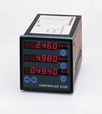
Type Codes Typenschlüssel
Messbereich 0.002.......2 l/min. Aufnehmersystem für hohe Temperaturen
Flow Meters VS
Baugröße 0.0005.....0.53 GPM = 0.02 Pick-up system for high temperature ranges
Volumensensor 0.004.......4 l/min. VS . . . . . . . - HT /.
Measuring 0.0011.....1.06 GPM = 0.04
range size 0.01.......10 l/min.
of flowmeter
VS . . . . . . . - . . . . . / .
0.0026.....2.64 GPM = 0.1
0.02.......18 l/min.
0.0053.....4.76 GPM = 0.2 Baureihe (werksseitig festgelegt) 1
Volumensensoren VS
0.03.......40 l/min. = Series (works-determined) 1 1
0.0079...10.57 GPM = 0.4
VSE-Normsteckeranschluss
0.05.......80 l/min. 1 = VSE-standard plug connection
0.0132...21.13 GPM = 1
kein Vorverstärker
0.1.......150 l/min.
0 = non pre-amplifier
0.0264...39.63 GPM = 2
integriert (Standardausführung)
1..........300 l/min.
1 = integrated (Standard design)
0.2642...79.25 GPM = 4
1 extern (für Mediumtemperatur 100˚C/212˚F)
Werkstoff Grauguss GGG 40 cast iron = G 2 = external (for medium temperature 100˚C/212˚F)
Material Edelstahl 1.4305 stainless steel = E
2 Betriebsspannung Standard-Ausführung
Anschlussart Anschlussplatte Subplate = P Supply voltage Standard-design
Type of connection Rohrleitung Piping = R A = 24 V DC
Hilfsanschluss Ohne Spülanschluss D = 12 V DC
Auxiliary port Without flushing port = 0 Betriebsspannung Ex-Ausführung EEx ia IIC T6
Supply voltage Ex-design EEx ia IIC T6
Messwerks- Kugellager
G = 24 V DC 1
lagerung Ball bearing = 1
Instrument K = 12 V DC
Spindellager
bearing 2 Spindle-bearing = 2 Anzahl der Aufnehmer No. of pick-ups
Bronze-Gleitlager 1 = 1 Aufnehmer 1 pick-up 1
Bronze-plain bearing = 3 1 = 2 Aufnehmer 2 pick-ups
Kohle-Gleitlager Feldplattenwiderstand Standardausführung=300Ω
Carbon-plain bearing = 4 1 = Differential magneto resistors standard design=300Ω
Stahl-Gleitlager Feldplattenwiderstand Ex-Ausführung = 1000 Ω
Steel-plain bearing = 5 2 = Differential magneto resistors Ex-design = 1000 Ω
Messwerks- Verkleinertes Spiel
toleranz Reduced tolerance = 1
Instrument Erläuterung zur Kurzbezeichnung
Normales Spiel
tolerance 2 der Dichtungsart
Normal tolerance = 2
Short term explanation of type of seals
Vergrößertes Spiel
Increased tolerance = 3 FPM ( FKM) = Fluor-Karbonkautschuk O-Ring
Spiel Stahl-Gleitlager Fluorocarbon Rubber O-Ring
Tolerance steel-plain bearing NBR = Acrylnitril-Butadien-Kautschuk O-Ring
= 4
Acryl-Nitrile Butadiene Rubber O-Ring
Dichtungsart FPM ( FKM) Standard = V PTFE = Polytetraflourethyleen O-Ring
Type of seal 2 NBR = P Polytetraflour Ethylene Rubber O-Ring
PTFE = T EPDM = Ethylen-Propylen-Dien-Kautschuk O-Ring
EPDM = E Ethylen-Propylene Dien Rubber O-Ring
Werkstoff Grauguss GGG 25 cast iron = G AP . . . . . . / . Baureihe (werksseitig festgelegt) 1
Subplates AP
Material Edelstahl 1.4305 stainless steel = E = Series (works-determined) 1
Zugehörige VS size AP size Sonderausführung
Volumensensor- VS 2.02 - VS 0.2 ––’ = 02 S = Special design
Baugröße VS 0.4 ––’ = 04 Standardausführung
Affilated VS N = Standard design
VS 1 - VS 2 ––’ = 1
flowmeter size
VS 4 ––’ = 4
Anschlussplatten AP
Ohne Spülanschluss
Anschlusslage seitlich side connection = S O = Without flushing connections
Connection
orientation unten bottom connection = U
Anschlussart G G G G G G G Andere Typennummern = Sonderausführung
G-Rohrgewinde- Other type nos. = special design
1 3 1 3
größen /4” /8” /2” /4” 1” 11/4” 11/2”
1 Sonderausführung auf Anfrage
Type of connection
A B C D E F G Special design upon request
G-pipe thread sizes
2 Wird werkseitig zur Anwendung festgelegt
NPT-Rohrge- 1
/4” 3
/8” 1
/2” 3
/4” 1” 11/4” 11/2” Works-determine to the application
windegrößen
NPT-pipe
3 NPT Rohrgewindegrößen und spezielle
NPT NPT NPT NPT NPT NPT NPT
thread sizes 3
Anschlussplatten mit SAE-Flansch auf Anfrage
J K L M N O P NPT pipe thread sizes and special subplates
with SAE-flanges on request
10Connection Example: 12 Volt Model with Anschlussbeispiel: 12 Volt Version mit
the accompanying Working Materials den dazugehörigen Betriebsmitteln
Channel 1
Channel 2
C
Zusammenstellung der sicherheitsrelevanten technischen Daten
List of safety relevant technical data
Volumensensor VSE-Anschlusskabel, blau Sicherheitsbarriere
Flowmeter PVC abgeschirmt; 4x0,38mm2 Safety barrier
Typ: VS .......-22K11/. VSE-connection cable, blue Typ: 9004/01-168-050-001
LCIE 02 ATEX 6146 X PVC shielded; 4x0,38mm2 PTB 02 ATEX 2008
II 1G EEx ia IIC T6 II (2) G [EEx ib] IIC
Ui = 20 Volt R = 0,055 Ω/m Uo = 16,8 V
Ii = 500 mA L = 0,72 µH/m (x) Io = 50 mA
Pi = 1,2 Watt CA-A = 110 pF/m (x) Po = 840 mW
Ri = 0 CA-S = 183 pF/m (x) Ui = 31,5 V
Li = 0 [(x) = gemessen bei 1000 Hz ] Ii = 40 mA
Ci = 2,4 nF [(x) = measured at 1000 Hz ]
IIC IIB
Zusammenfassung: Bedingt durch die technischen Daten der
elektronischen Sicherheitsbarrieren vom Typ 9004/01-168-050-001 Lo/mH 0,86 0,20 2,5 2,0 1,0
ist eine Anwendung des Volumensensors möglich für: Co/µF 0,16 0,23 1,2 1,3 1,6
Summary: As a result of the technical data of the electronic safety
Sicherheitsbarriere
barrier Type 9004/01-168-050-001, the flowmeter can be used for:
Safety barrier
Typ: 9001/01-168-050-101
Gerätegruppe Devices group II
PTB 01 ATEX 2088
Gerätekategorie Devices category 2G
II (1/2) G [EEx ia/ib] IIC/IIB
Gruppe Group II C
Uo = 16,8 V
Kategorie Category ib
Io = 50 mA
Temperaturklasse Temperature class T6
Po = 210 mW
IIC IIB
Lo/mH 15 56
Co/µF 0,39 2,29
11Connection Example: 24 Volt Model with Anschlussbeispiel: 24 Volt Version mit
the accompanying Working Materials den dazugehörigen Betriebsmitteln
C
C
C
Zusammenstellung der sicherheitsrelevanten technischen Daten
List of safety relevant technical data
Volumensensor VSE-Anschlusskabel, blau Sicherheitsbarriere
Flowmeter PVC abgeschirmt; 4x0,38mm2 Safety barrier
Typ: VS .......-22G11/. VSE-connection cable, blue Typ: 9004/51-206-050-001
LCIE 02 ATEX 6146 X PVC shielded; 4x0,38mm2 PTB 02 ATEX 2008
II 1G EEx ia IIC T6 II (2) G [EEx ib] II B
Ui = 28 Volt R = 0,055 Ω/m Uo = 20,6 V
Ii = 280 mA L = 0,72 µH/m (x) Io = 50 mA
Pi = 1,2 Watt CA-A = 110 pF/m (x) Po = 1030 mW
Ri = 0 CA-S = 183 pF/m (x) Ui = 31,5 V
Li = 0 [(x) = gemessen bei 1000 Hz ] Ii = 40 mA
Ci = 2,4 nF [(x) = measured at 1000 Hz ]
IIC IIB
Zusammenfassung: Bedingt durch die technischen Daten der Lo/mH ----------- ---------- 2,5 2,0 1,0
elektronischen Sicherheitsbarriere vom Typ 9004/51-206-050-001 Co/µF ----------- ---------- 0,58 0,58 0,62
ist eine Anwendung des Volumensensors möglich für:
Sicherheitsbarriere
Summary: As a result of the technical data of the electronic safety Safety barrier
barrier Type 9004/51-206-050-001, the flowmeter can be used for: Typ: 9001/01-280-020-101
PTB 01 ATEX 2088
Gerätegruppe Devices group II II (1/2) G [EEx ia/ib] IIC/IIB
Gerätekategorie Devices category 2G Uo = 28 V
Gruppe Group II B Io = 20 mA
Kategorie Category ib Po = 140 mW
Temperaturklasse Temperature class T6
IIC IIB
Lo/mH 50 50
12 Co/µF 0,083 0,65Pick-up System for High Temperature Ranges Aufnehmersystem für hohe Temperaturen
Option for stainless-steel Option für Edelstahl – Volu-
flowmeters VS 0,1 ..... VS 4 mensensoren VS 0,1 ….VS 4
The pick-up system consists of one or Das Aufnehmersystem besteht aus
two sensor units which are screwed into einer Sensoreneinheit, welche in den
the cover of the VS flowmeter and of Deckel des VS-Volumensensors einge-
a downstream switched amplifier. This schraubt ist, und einem nachgeschalte-
amplifier is connected with the flowme- ten Verstärker. Der Verstärker ist über ein
ter by means of a temperature resistant temperaturbeständiges Kabel mit dem
cable and has to be installed outside Volumensensor verbunden und muss
the high temperature area, where the außerhalb des Hochtemperaturbereichs
ambient temperature should not exceed installiert sein. Die Umgebungstempe-
50°C (122°F). ratur sollte hier 50° nicht übersteigen.
Plug Connections Diagram Stecker – Anschlussbild
1 : Supply +U = 10 ...30V 1 : Versorgung +U = 10 ...30 V
2 : Digital signal 2 : digitale Signale
3 : Supply -U = 0 V 3 : Versorgung -U = 0 V
4 : None 4 : frei
Depending on the amplifier version, Anschluss: Abhängig von der Ausführung des
the digital signals are output as PNP PNP-Signalausgabe Verstärkers werden die digitalen
or NPN switching signals. The fol- Connection: Signale als PNP- oder NPN- Signale
PNP-switching
lowing pictures show the respective ausgegeben. Die folgenden Bilder zei-
connection of the electrinic readout: gen den jeweiligen Anschluss der Aus-
werteelektronik:
For long cable lenghts and high Anschluss: Bei großen Leistungslängen und
input impedance it is recommended to NPN-Signalausgabe hoher Eingangsimpedanz der Auswer-
use shielded cables and pull down (PNP- Connection: teelektronik, empfiehlt es sich, abge-
NPN-switching
signal) or pull up (NPN-signal) resistor. schirmte Kabel zu verwenden und einen
Pull-Down (PNP-Signal) oder Pull-Up-
Widerstand (NPN-Signal) einzusetzen.
13Technical Data Technische Daten
Sensor unit Sensoreneinheit
Medium temperature –40°C … 210°C Medientemperatur –40°C … 210°C
–40°F … 410°F Aufnehmerzahl 1 oder 2 Sensoren
Number of pic – ups 1 or 2 pick ups Aufnehmer Magnetoresistiv
Pick – up Magnetoresistive Elektrischer Anschluss Fester Kabelanschluss mit PG-
Electrical Connection PG – cable fitting Verschraubung
Isolation – Protection IP 64 Isolations-Schutzart IP 64
Amplifier Verstärker
Supply voltage Ub = 10 ... 30V DC +/– 10% Versorgungsspannung Ub = 10 ... 30V DC +/– 10-%
Current consumption Ib = ca. 15mA (idle motion, without lead) Stromaufnahme Ib = ca. 15mA (Leerlauf, ohne Last)
Signal output PNP High Signal: Us=Ub-1V, Is=25mA max Signalausgabe PNP High Sign.:-Us=Ub-1V,Is=25mA max.
Signal output NPN Low Signal: Us=0V, Is=25mA max Signalausgabe NPN Low Sign.: Us=0V, Is=25mA max.
Electrical Connection 4 pole round plug M 12 Elektrischer Anschluss 4 pol. Rundstecker M 12
Max. ambient temp. 50°C (122°F) Max. Umgebungstemp. 50°C
Protection – class IP 64 Schutzart IP 64
Pull – Down resistor 4,7 …10 KΩ Pull – Down Widerstand 4,7 …10 KΩ
Pull – Up resistor 4,7 …10 KΩ Pull – Up Widerstand 4,7 …10 KΩ
Flowmeter Dimensions Abmessungen Volumensensor
Ansicht X
Vorverstärker HTS1 – NPN / PNP
View X
Amplifier HTS1 – NPN / PNP
89
M12 x 1
A
ø17
L
Zentrierbohrung Kabellänge 1m
Cable length 1m
Centre bores
P
M
N
VSE D-58809 Neuenrade
øG
K
O-Ring
E
X D
Baugröße Gewicht
Size A D E øG K L M N P O-Ring Weight kg
VS 0,1 100 M6 9 ø9 61 70 40 20 22 11 x 2 3.3
VS 0,2 100 M6 9 ø9 61 70 40 20 22 11 x 2 3.6
VS 0,4 115 M8 16.5 ø 16 63.5 80 38 34 22 18 x 2.62 4.9
VS 1 130 M8 12 ø 16 68 84 72 34 22 18 x 2.62 6.7
VS 2 130 M8 12 ø 16 85 84 72 34 22 18 x 2.62 8.3
VS 4 180 M 12 20 ø 30 110 46 95 45 12 36.17 x 2.62 18.3
14Customer Specific Solutions Kundenspezifische Sonderlösungen
Customer specific design for Sondergeräte für spezifische
special applications, Anwendung z. B.
for example
Offshore Offshore
Automobile industry Fahrzeugtechnik
Process control Prozessmesstechnik
Temperatures up to 210°C (410°F) Temperaturen bis 210°C
Pressures 700 bar Drücke bis 700 bar
Weight improvement up to Gewichtsoptimierung
< 400 g possible < 400 g möglich
15Electronic Displays Elektronische Auswertgeräte
with Analog Output mit Analogausgang
Flow Rate Measuring Instrument MF1 MF1 Durchfluss-Messgerät MF1
for 2- or 1-channel flowsensor für 2- oder 1-kanaligen Durchfluss-Sensor
Flow direction indicator with switching Durchflussrichtungsanzeige mit Schalt-
output (0 V / 5 V) ausgang (0 V / 5 V)
2 opto-coupler limit value outputs, limit 2 Optokoppler Grenzwertausgänge,
values are individually adjustable Grenzwerte frei einstellbar
Analog output with flow rate direction Analogausgang auch mit Durchflussrich-
dependent voltage-/current-polarity is tungsabhängiger Strom-/Spannungs-
availble Polarität lieferbar
0 … (±) 10 V 0 … (±) 10 V
0 … (±) 20 mA 0 … (±) 20 mA
4 … 20 mA
4 … 20 mA
A power supply for flowsensor is
Spannungsversorgung für Durchfluss-
integrated 24 V DC / 50 mA
Sensor integriert 24 V DC / 50 mA
Volume-Measuring Instrument INF 8-Q Volumen-Messgerät INF 8-Q
INF 8-Q für 2-kanaligen Durchfluss-Sensor
for 2-channel flowsensor 4 Grenzwertausgänge, jeweils Transistor-
4 limit value outputs, each as transistor ausgang mit 2 oder optional 4 Relaisaus-
output and 2 or 4 optional relay outputs; gängen; Grenzwerte frei programmierbar
limit values are individually programmable 12 Bit-Analogausgang mit Volumenrich-
12 Bit-analog output with volume- tungsabhängiger Spannungspolarität
direction dependent voltage polarity 0 … ± 10 V
0 … ± 10 V 0 … 20 mA
0 … 20 mA 4 … 20 mA
4 … 20 mA
Spannungsversorgung für Durchfluss-
A power supply for flowsensor is Sensor integriert 20-25 V DC / 40-mA,
integrated 20-25 V DC / 40 mA,
nicht stabilisiert
not stabilized
PC-Schnitstelle: optional RS 232
PC-Interface: option RS 232 or
oder RS 485
RS 485
Flow Rate and Volume PAXI Durchfluss- und Volumenmess-
Measuring Instrument PAXI gerät PAXI
for 2- or 1-channel flowsensor für 2- und 1-kanaligen Durchfluss-Sensor
Durchfluss- oder Volumenanzeige pro-
Flow rate- or volume-display programm- grammierbar, mit Linearisierungsfunktion
able, with linearizer function 12 Bit-Analogausgang
12 Bit-analog output 0 … 10 V
0 … 10 V 0 … 20 mA
0 … 20 mA 4 … 20 mA
4 … 20 mA 2 Grenzwert-Relaisausgänge
2 limit value-relay outputs PC-Schnittstelle
PC-Interface RS 232 or RS 485 Spannungsversorgung für den Durchfluss-
A power supply for flowsensor is integra- Sensor integriert 12 Volt/100mA
ted 12 Volt DC / 100 mA
16Flow Rate Measuring Instrument DPZ-F
Durchflussmessgerät DPZ-DF
DPZ-F
für 2- und 1-kanaligen Durchfluss-
for 2- or 1-channel flowsensor
Sensor
Flowmeter type selectable by menue
Volumensensortype wählbar per Menü
Flowmeter-direction indicator
Durchfluss Richtungsanzeige
16 Bit- analog output
16 Bit-Analogausgang
0 … ± 10 V
0 … ± 10 V
0 … ± 20 mA
0 … ± 20 mA
4 … 20 mA
4 … 20 mA
2 limit value outputs
2 Grenzwertausgänge
Solid-state relay
Halbleiterrelais
PC-Interface RS 232 or RS 485
PC-Schnittstelle RS 232 oder RS 485
A power supply for flowsensor is inte-
Spannungsversorgung für den Durchfluss-
grated 24 Volt DC / 100 mA
sensor integriert 24 Volt DC / 100mA
Universal Measuring Instrument VFM 320 Universal Messgerät VFM 320
VFM 320 for dynamic process measu- für dynamische Prozessmessungen
rements and closed loop controls und Regelungen
Flow rate volume and ratio measurements Durchfluss-, Volumen- und Verhältnissmessung
as well as measurement and control of sowie Messung und Steuerung von Schuss-
volume-shots or mass-shots in 2-compo-
volumen – oder Schussmassen-Vorgängen
nent mixing systems
für 2-Komponenten Mischungsanlagen
Signal processing of 2 flow sensors
Signalverarbeitung von 2 Durchfluss-Sen-
with 2-channel signal outputs
soren mit zweikanaliger Signalausgabe
2 independent dynamic analog outputs
with 16 Bit digital-analog converter 2 unabhängige dynamische Analog-
D/A-converter transformation time: ausgänge mit 16 Bit Digital/Analog-Instruments for Impulse Conditioning Geräte für die Impulsaufbereitung
Frequency-/analog converter DIGFU 1 Frequenz-/Analogwandler
DIGFU 1 DIGFU 1
for 1-channel or 2-channel flow rate- für 1-kanaligen oder 2-kanaligen
sensor whose output frequency has Durchfluss-Sensor, dessen Ausgabe-
to be converted into a linear analog frequenz in einen linearen analogen
voltage value Spannungswert umgewandelt wer-
Converter output signal for operation den muss
with 1-channel flowsensor Ausgangssignale für 1-kanaligen Durch-
0. . .10 V fluss-Sensor
0. . .20 mA 0. . .10 V
4. . .20 mA 0. . .20 mA
Converter output signal with flow 4. . .20 mA
direction polarity for operation with Ausgangssignale mit Durchflussrichtungs-
2-channel flowsensor Polarität für 2-kanaligen Durchfluss-Sensor
0. . . ± 10 V 0. . . ± 10 V
0. . . ± 20 mA 0. . . ± 20 mA
Evaluation of flow direction via digital Zusätzliches digitales Ausgangssignal für
output signal possible if a 2-channel flow die Auswertung der Durchflussrichtung bei
sensor is connected 2-kanaligen Durchfluss-Sensor
Proportional to flow frequency a digital out- Proportional zur Durchflussfrequenz ist
put frequency signal with multiplier factor eine digitale Ausgangsfrequenz mit
is adjustable
Multiplikator einstellbar
Signal converter PGW-1 PGW-1 Pegelwandler PGW-1
for 2- or 1-channel flowsensors to für 2- oder 1-kanalige Durchfluss-
convert flowsensor output signals Sensoren zur Umsetzung der Durch-
into other voltage leves fluss-Sensor-Ausgangssignale in andere
Spannungspegel
For example: chart recorder with z.B. für Messwertschreiber mit Impuls-
impulse input, Forward- / Reverse-counter, eingang Vor-Rückwartszähler, Computer,
Computer, PC- and PLC-controls PC und SPS-Steuerungen
Available output voltages: Verfügbare Ausgangsspannungen:
TTL 5 V, 8 V, 12 V, CMOS 15 V TTL 5 V, 8 V, 12 V, CMOS 15 V
Power supply / current consumption: Spannungsversorgung/Stromaufnahme:
10 . . . 30 V DC, 20 mA 10 . . . 30 V DC, 20 mA
without flowsensor ohne Durchfluss-Sensor
Inverted and non inverted output signal Invertiertes und nicht invertiertes Ausgangs-
for both channels integrated among signal für beide Kanäle vorhanden u. a.
other things for connection on differential zur Ansteuerung von differenziellen Zähl-
count inputs to achieve a distortion free sig- eingängen zwecks störungsfreier Signal-
nal transmission over long cable übertragung über große Leitungslängen
distances
Safety barriers 9001… and 9001 … and 9004 … Sicherheitsbarrieren 9001 … und
9004 … 9004 …
for VS flowmeters in Ex-design für VS Volumsensoren in Ex-Schutzaus-
EEx ia IIC T6 führung EEx ia IIC T6
Economical interfaces without galvanic iso- Preiswerte Trennstufen ohne galvanische
lation between intrinsically safe and non- Trennung zwischen eigensicheren und nicht
intrinsically safe circuits eigensicheren Stromkreisen
They must be installed in the safe area Sind außerhalb des explosionsgefährde-
ten Bereiches zu installieren
They are used to limit the electrical power
Begrenzen die in einem eigensicheren
into an intrinsically safe circuit in such a
Stromkreis eingespeiste Leistung so, dass
way that neither sparks nor thermal
weder durch Funken noch durch
effects (hot surfaces) can cause an ignition
thermische Effekte (heiße Oberflächen)
eine Zündung erfolgen kann
Connection diagram and exact
Anschlussbild und genaue
order nos. see pages 11
Typenbezeichnung siehe Seite 11
18Test Equipment Testeinrichtung
Testbox TB-1 TB-1 Testbox TB-1
for the simulation of 1-channel or 2- zur Simulation von 1-kanaligen oder 2-
channel flowsensor signals kanaligen Durchfluss-Sensor-Signalen
Testing and adjustment of electronic Test- und Einstellarbeiten an elektro-
processing equipment is possible without nischen Auswertegeräten sind hiermit
connecting a flowsensor ohne den Anschluss des Durchfluss-
Sensors möglich
5 digit LCD frequency display with one 5-stellige LCD-Frequenzanzeige mit
decimal point einer Kommastelle
Frequency range 0-2 kHz with separate Frequenzbereich 0-2 kHz mit getrennter
rough - and fine-adjustment via 10 turn- Grob- und Feineinstellung über 10-Gang
potentiometer Potentiometer
2 output channels with selectable ± 90° 2 Ausgangskanäle mit umschaltbarem
phase displacement for the alternating Phasenversatz ± 90° zur Simulation des
simulation of flow direction Durchflussrichtungswechsels
Electronic Displays Elektronische Auswertegeräte
without Analog Output ohne Analogausgang
Volume-presetcounter and GEL 103 Volumen-Vorwahlzähler und
batch-counter GEL 103 Chargenzähler GEL 103
for 2- or 1-channel flowsensor für 2- oder 1-kanaligen Durchfluss-
Sensor
Display-values for actual volume value Anzeigewert für Volumen-Istwert und
and 2 volume preset values will be Volumen-Vorwahlwerte werden gleichzei-
displayed simultaneously tig angezeigt
2 limit value-relay – and transistor outputs, 2 Grenzwert-Relais- und Transistoraus-
1 transistor output for batch preset control gänge, 1 Transistorausgang für Chargen-
vorwahl
Phase discriminator for 2-channel flow rate Phasendiskriminator für 2-kanaligen
sensor with single, double or quadruple Durchfluss-Sensor mit 1-facher, 2-facher
volume-impulse edge evaluation pro- oder 4-facher Volumen-Impulsflanken-
grammable auswertung programmierbar
A power supply for flowsensor is Spannungsversorgung für Durchfluss-
integrated 24 V DC ± 10 %, max. 60 mA Sensor integriert 24 V DC ± 10 %, max.
60 mA
Notes/Sketches Notizen/Skizzen
19Worldwide service Service Weltweit
Service Weltweit
Qualifizierte Beratung
durch langjährige
Kooperationspartner
_ persönlich
_ kompetent
_ leistungsstark
Worldwide service
Qualified advice
through longstanding
cooperation partners
_ personal
_ competent
_ efficient
Products Produkte
Precision gear type flowmeters Präzisions-Zahnrad-Volumensensoren
for general industrial applications für allgemeine industrielle Anwendungen
Stainless steel gear type flowmeters Edelstahl-Zahnrad-Volumensensoren
for special applications für besondere Anwendungen
Turbine flowmeters Turbinen-Durchfluss-Sensoren
Standardized and individual Standardisierte und individuelle
electronic readouts elektronische Auswertgeräte
Electronic devices for special solutions Elektronische Geräte für Sonderlösungen
in measurement-, control- and regula- in der Mess-, Steuer- und Regelungs-
tion technology technik
VSE Volumentechnik GmbH
Hönnestraße 47
58809 Neuenrade / Germany
Phone +49 (0) 23 94 / 6 16 30
Fax +49 (0) 23 94 / 6 16 33
11/05
info@vse-flow.com
www.vse-flow.com
www.plakart.de
distributed by:
20Sie können auch lesen