Novel 0- and 2-dimensional electron donor-acceptor systems for solar energy conversion Neuartige 0- und 2-dimensionale Elektronen Donor-Akzeptor ...
←
→
Transkription von Seiteninhalten
Wenn Ihr Browser die Seite nicht korrekt rendert, bitte, lesen Sie den Inhalt der Seite unten
Novel 0- and 2-dimensional electron donor-acceptor
        systems for solar energy conversion

Neuartige 0- und 2-dimensionale Elektronen Donor-
Akzeptor Systeme für die Solare Energieumwandlung

             Der Naturwissenschaftlichen Fakultät
    der Friedrich-Alexander-Universität Erlangen-Nürnberg
                             zur
           Erlangung des Doktorgrades Dr. rer. nat.

                        vorgelegt von
                        Tobias Scharl
                          aus Fürth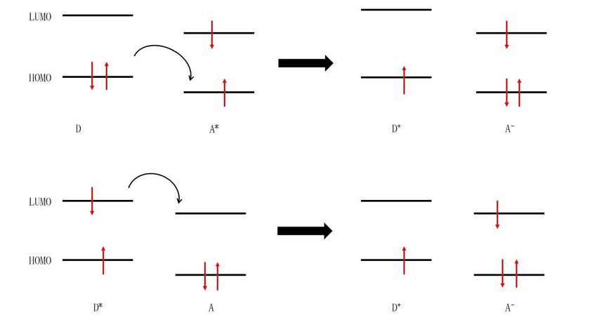
Als Dissertation genehmigt von der Naturwissenschaftlichen Fakultät der Friedrich-
                       Alexander-Universität Erlangen-Nürnberg

Tag der mündlichen Prüfung:              04.03.2022

Vorsitzender des Promotionsorgans:       Prof. Dr. Wolfgang Achtziger

Gutachter:                               Prof. Dr. Dirk M. Guldi

                                         Prof. Dr. Andreas Hirsch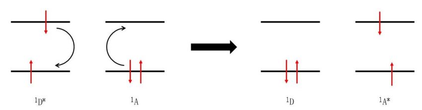
Die vorliegende Arbeit entstand im Zeitraum von September 2016 bis März 2022 im Department
Chemie und Pharmazie (Lehrstuhl für Physikalische Chemie I) der Friedrich-Alexander-Universität
Erlangen-Nürnberg im Arbeitskreis von Prof. Dr. Dirk M. Guldi.
Table of content

1. Abstract . . . . . . . . . . . . . . . . . . . . . . . . . . . . . . . . . . . . . . . . . . . . . . . .   1
2. Kurzzusammenfassung . . . . . . . . . . . . . . . . . . . . . . . . . . . . . . . . . . . . . . . .        3
3. Introduction . . . . . . . . . . . . . . . . . . . . . . . . . . . . . . . . . . . . . . . . . . . . . .   5
4. Theoretical background . . . . . . . . . . . . . . . . . . . . . . . . . . . . . . . . . . . . . . .       8
     4.1 Photophysical processes . . . . . . . . . . . . . . . . . . . . . . . . . . . . . . . . . . . 8
     4.2 Molecular building blocks . . . . . . . . . . . . . . . . . . . . . . . . . . . . . . . . . . . 12
           4.2.1    Carbon nanodots . . . . . . . . . . . . . . . . . . . . . . . . . . . . . . . . . . . 12
                    4.2.1.1 Synthesis . . . . . . . . . . . . . . . . . . . . . . . . . . . . . . . . . . 12
                    4.2.1.2 Structure . . . . . . . . . . . . . . . . . . . . . . . . . . . . . . . . . . 14
                    4.2.1.3 Photophysics . . . . . . . . . . . . . . . . . . . . . . . . . . . . . . . . 15
           4.2.2    Transition metal dichalcogenides . . . . . . . . . . . . . . . . . . . . . . . . . 17
           4.2.3    Porphyrin . . . . . . . . . . . . . . . . . . . . . . . . . . . . . . . . . . . . . . . 21
           4.2.4    Phthalocyanine . . . . . . . . . . . . . . . . . . . . . . . . . . . . . . . . . . . . 23
           4.2.5    Rylene diimides. . . . . . . . . . . . . . . . . . . . . . . . . . . . . . . . . . . . 25
           4.2.6    Extended tetrathiafulvalene . . . . . . . . . . . . . . . . . . . . . . . . . . . . 27
           4.2.7    Tetracyano-p-quinodimethane . . . . . . . . . . . . . . . . . . . . . . . . . . 29
5. Objective . . . . . . . . . . . . . . . . . . . . . . . . . . . . . . . . . . . . . . . . . . . . . . . 31
6. Projects . . . . . . . . . . . . . . . . . . . . . . . . . . . . . . . . . . . . . . . . . . . . . . . . 32
     6.1 Carbon nanodot containing systems . . . . . . . . . . . . . . . . . . . . . . . . . . . . 32
     6.2 Transition metal dichalcogenide containing systems . . . . . . . . . . . . . . . . . . . 50
7. Conclusion . . . . . . . . . . . . . . . . . . . . . . . . . . . . . . . . . . . . . . . . . . . . . . . 60
8. Zusammenfassung . . . . . . . . . . . . . . . . . . . . . . . . . . . . . . . . . . . . . . . . . . 62
9. Acknowledgements . . . . . . . . . . . . . . . . . . . . . . . . . . . . . . . . . . . . . . . . . . 65
10. Abbreviations . . . . . . . . . . . . . . . . . . . . . . . . . . . . . . . . . . . . . . . . . . . . . 66
11. References . . . . . . . . . . . . . . . . . . . . . . . . . . . . . . . . . . . . . . . . . . . . . . . 70
12. List of publications . . . . . . . . . . . . . . . . . . . . . . . . . . . . . . . . . . . . . . . . . . 80
    12.1 Publications used in this thesis . . . . . . . . . . . . . . . . . . . . . . . . . . . . . . . 80
    12.2 Other publications . . . . . . . . . . . . . . . . . . . . . . . . . . . . . . . . . . . . . . . 81
13. Appendix . . . . . . . . . . . . . . . . . . . . . . . . . . . . . . . . . . . . . . . . . . . . . . . . 82
1. Abstract
The consequences of man-made climate change are the most important and most challenging
problems that we have to solve in the 21st century. One of the many challenges is to provide energy
to an ever-growing world population, while at the same time, transition occurs from the use of fossil
fuels for energy generation to greenhouse gas free energy sources. Due to the abundance of solar
energy, solar cells will play a major role in the energy mix of our future. Hence, it is our interest to
improve the performance of solar cells and to reduce their costs. To do so, new materials are
developed and photophysically analysed.
The aim of this thesis is to investigate several new materials for the use in artificial photosynthesis.
The focus lies hereby on the ground - and excited state interactions of several electron donor-
acceptor systems and on the analysis of photoinduced charge transfer reactions. Understanding these
systems will help to tailor and improve new solar cells. To do so, a range of spectroscopic techniques
have been applied. Steady-state absorption and emission spectroscopy, as well as electrochemical
techniques like cyclic voltammetry and differential pulse voltammetry, have been used to study the
ground state interactions of these electron donor-acceptor systems. The excited state processes and
interactions, such as electron- or energy transfer events, have been studied with the help of femto-
and nanosecond resolved transient absorption spectroscopies.
This thesis consists of two parts. The first part deals with the use of quasi-0-dimensional carbon
nanodots in electron donor-acceptor systems. The ambivalent binding motives of the element carbon
results in a variety of different carbon-based materials, with each having unique and outstanding
physical properties. Carbon nanodots are one of these materials, with, among others, promising
applications in the field of artificial photosynthesis.
Pressure synthesized carbon nanodots have been analysed as electron acceptors as well as electron
donors in covalently linked electron donor-acceptor systems, by a functionalization with either
electron donating π-extended tetrathiafulvalene, or with electron accepting tetracyano-p-
quinodimethane. Also, non-covalent interactions in the form of amidinium–carboxylate salt bridges
between carbon nanodots and porphyrins have been studied. After this, the focus was placed on other
types of carbon nanodots. Graphene quantum dots have been photophysically investigated as electron
acceptors. After that, symmetry breaking interactions between phthalocyanines, that are attached to
nitrogen-doped carbon nanodots have been explored. Finally, the complex interactions between
1nitrogen-doped carbon nanodots and naphthalene diimides and/or perylene diimides were in the focus of this study. The second part of this thesis deals with the use of 2-dimensional transition metal dichalcogenides in electron donor-acceptor systems. The most common members of this class of materials are molybdenum disulfide and tungsten disulfide, which are both 2-dimensional semiconductors. Hence, the photophysics of these materials was in the focus of our attention. The covalent functionalization of molybdenum disulfide with a porphyrin was studied photophysically, while a non-covalent functionalization of tungsten disulfide with a perylene diimide was examined. 2
2. Kurzzusammenfassung

Die Folgen des vom Menschen verursachten Klimawandels sind die wichtigsten und schwierigsten

Probleme, die wir im 21. Jahrhundert zu lösen haben. Eine der vielen Herausforderungen besteht

darin, eine ständig wachsende Weltbevölkerung mit Energie zu versorgen und gleichzeitig von der

Verwendung fossiler Brennstoffe zur Energieerzeugung auf treibhausgasfreie Energiequellen

umzustellen. Da Solarenergie in Hülle und Fülle vorhanden ist, werden Solarzellen eine wichtige Rolle

im Energiemix der Zukunft spielen. Daher ist es in unserem Interesse, die Leistung von Solarzellen

zu verbessern und ihre Kosten zu senken. Zu diesem Zweck werden neue Materialien entwickelt und

photophysikalisch untersucht.

Das Ziel dieser Arbeit ist es, verschiedene neue Materialien für den Einsatz in der künstlichen

Photosynthese zu untersuchen. Der Schwerpunkt liegt dabei auf den Grund- und angeregten

Zustandswechselwirkungen verschiedener Elektronendonor-Akzeptor-Systeme und auf der Analyse

von photoinduzierten Ladungstransferreaktionen. Das Verständnis dieser Systeme wird dazu

beitragen, neue Solarzellen zu designen und zu verbessern. Zu diesem Zweck wurde eine Reihe von

spektroskopischen Techniken angewandt. Die stationäre Absorptions- und Emissionsspektroskopie

sowie elektrochemische Techniken, wie die zyklische Voltammetrie und die differenzielle

Pulsvoltammetrie,    wurden     eingesetzt,   um    die   Grundzustandswechselwirkungen       dieser

Elektronendonor- und -Akzeptorsysteme zu untersuchen. Die Prozesse und Wechselwirkungen im

angeregten Zustand, wie z. B. Elektronen- oder Energietransferereignisse, wurden mit Hilfe der

Femto- und Nanosekunden-aufgelösten transienten Absorptionsspektroskopie untersucht.

Diese Arbeit besteht aus zwei Teilen. Der erste Teil befasst sich mit der Verwendung von quasi-0-

dimensionalen Kohlenstoff-Nanopunkten in Elektronendonor-Akzeptor-Systemen. Die ambivalenten

Bindungsmotive des Elements Kohlenstoff führen zu einer Vielzahl verschiedener kohlenstoffbasierter

Materialien, von denen jedes einzigartige und herausragende physikalische Eigenschaften aufweist.

Kohlenstoff-Nanopunkte sind eines dieser Materialien, das unter anderem vielversprechende

Anwendungen im Bereich der künstlichen Photosynthese bietet.

Drucksynthetisierte Kohlenstoff-Nanopunkte wurden sowohl als Elektronenakzeptoren als auch als

Elektronendonoren in kovalent verknüpften Elektronendonor-Akzeptor-Systemen untersucht, indem

sie entweder mit dem elektronenspendenden π-vergrößerten Tetrathiafulvalen oder mit dem

                                                                                                   3
elektronenakzeptierenden Tetracyano-p-Chinodimethan funktionalisiert wurden. Auch nicht- kovalente Wechselwirkungen in Form von Amidinium-Carboxylat-Salzbrücken zwischen Kohlenstoff- Nanopunkten und Porphyrinen wurden untersucht. Danach wurde der Schwerpunkt auf andere Arten von Kohlenstoff-Nanopunkten gelegt. Graphen-Quantenpunkte wurden photophysikalisch als Elektronenakzeptoren untersucht. Danach wurden symmetriebrechende Wechselwirkungen zwischen Phthalocyaninen, die an stickstoffdotierte Kohlenstoff-Nanopunkte gebunden sind, erforscht. Schließlich standen die komplexen Wechselwirkungen zwischen stickstoffdotierten Kohlenstoffnanopunkten und Naphthalindiimiden und/oder Perylendiimiden im Mittelpunkt dieser Studie. Der zweite Teil dieser Arbeit befasst sich mit der Verwendung von 2-dimensionalen Übergangsmetall- Dichalcogeniden in Elektronendonor-Akzeptor-Systemen. Die häufigsten Vertreter dieser Materialklasse sind Molybdändisulfid und Wolframdisulfid, welche beide zweidimensionale Halbleiter sind. Daher stand die Photophysik dieser Materialien im Mittelpunkt unseres Interesses. Die kovalente Funktionalisierung von Molybdändisulfid mit einem Porphyrin wurde photophysikalisch analysiert, während eine nicht-kovalente Funktionalisierung von Wolframdisulfid mit einem Perylendiimid untersucht wurde. 4
3. Introduction

In the 2011 Paris climate agreement, all countries in the world obliged themselves to fight manmade

climate change. The goal was to keep the warming of the earth below 1.5 °C compared to

preindustrial temperatures. Exceeding 1.5 °C warming will lead to an increase in drastic weather

phenomena like droughts, heatwaves or floods, desertification, rising sea levels due to melting of

arctic ice, crop failure and subsequent famine, mass extinction, mass migration and war. 1 Even though

scientists are warning since decades about the negative impacts of a changing climate, the general
                                             2
and political acceptance was not granted.        With the Paris agreement, the world now has a clear

roadmap how the climate crisis should be tackled. The plan is to stepwise reduce the emission of

greenhouse gases, like carbon dioxide (CO2). However, it was left to all countries individually how to

implement these changes. Germany plans to reduce the CO2 emissions compared to emissions in

1990 by 65 % until 2030, by 88 % until 2040 and wants to become carbon neutral by 2045. 3 In this

instance, carbon neutral means zero emission of carbon-based greenhouse gases like CO2 or methane

(CH4). In addition to the replacement of CO2 by focusing on energy sources like oil, coal or gas, the

global energy demand keeps rising from a growing world population and the transition of some former
                                                                           4
developing countries to industrial nations, like China, Brazil or India.       Hence, the transition from

fossil fuels to renewable energies will be the most challenging problem of the 21’st century.

Renewable energy sources include wind, solar, biomass, geothermal, and hydroelectric. Every energy

source comes with its unique set of advantages and drawbacks and hence the energy mix of our future

will probably not consist of one primary energy source, but a mixture of several ones. However, since

the sun irradiates the earth annually with a power of 1.73 * 10 14 kW, which exceeds the global energy

demand more than 100 million times, solar energy conversion has the biggest potential to replace

fossil fuels. 4 In general, thinking of enhancing the energy output of photovoltaic cells, one can use

two strategies. Either the efficiency of a single solar cell is improved by developing new materials or

by optimizing the cell structure, in order to increase the amount of energy generated from a single

solar cell. Or the price of solar cells is reduced drastically, in order to boost the amount of deployed

solar cells and, hence, the overall energy generated by photovoltaics.

A conventional silicon solar cell is based on the interplay of two differently doped silicon materials.

On one side, doping silicon (Si) with an element with one additional valence electron, like phosphorus

(P), antimony (Sb) or arsenic (As) leads to the addition of a single occupied orbital with an energy

                                                                                                       5
just below the Si conduction band. This is referred to as n-doping. On the other hand, doping Si with
an element with one electron less, like boron (B), aluminium (Al) or gallium (Ga) is referred to as p-
doping. Here an empty orbital just above the Si valence band is introduced. The combination of both
types of materials leads to p-n junctions at the interface. An electron transfer from the energetically
high lying orbital on the n-doped side to the empty orbital on the p-doped side gives rise to a
diffusion current. Since this electron originates from the doped atom on the n-side, it leaves behind
a positive charge which is located on the latter and hence trapped in the Si crystal lattice. Similarly
on the p-side, the doped atom gets reduced and, hence, a voltage builds up across the p-n junction,
which is opposite from the diffusion current, until an equilibrium is reached. Photoexcitation of an
electron from the Si valence band into the conduction band produces a bound electron-hole pair, an
exciton, which is split into the respective charge carriers by the electric potential of the p-n junction.
Thus, a voltage and a current are generated. The most expensive step in the production of a Si solar
cell is the purification of the Si itself. The production of a single crystal of Si from molten Si at around
1400°C is energy intensive and, thus, expensive. 5 The efficiency of a single junction Si solar cell is
6
limited by the SHOCKLEY-QUEISSER limit to a maximum of 33%. However, this limit can be
overcome by the use of multi junction tandem architectures 7, hot carrier 8 or intermediate band solar
cells 9 or processes that result in the generation of multiple charge carriers 10 such as singlet fission 11.
Thinking of ‘cheaper’ solar cells, it is always a good idea to look at nature. In natural photosynthesis,
the light harvesting complex, consisting of chlorophyll a and b as well as carotenoids, in the
photosystem II (PS II) absorbs light and generates an exciton. The exciton is then transferred via a
series of energy transfers to a reaction centre, where a Mg-porphyrin P680 is excited. The excited
electron is subsequently separated from its hole and transferred via a series of electron transfer
reactions of plastoquinone and the cytochrome-b6f complex to the photosystem I (PSI). The hole in
P680+ is refilled by a manganese cluster, which catalyses the formation of oxygen. On the way from
PS II to PS I a proton gradient across the cell membrane builds up, which is used by the ATP-
synthase to produce adenosine triphosphate (ATP), a molecule that can store the harvested light
energy and transfer it to other parts in the cell. In the PS I, a second porphyrin P700, with its own
light harvesting complex is excited by light. The excited electron is transferred to the ferredoxin-
NADP+-reductase, which reduces NADP+ to NADPH. NADPH and ATP are subsequently used to
build sugars in the CALVIN cycle, while the hole in P700+ is refilled by the electron from PS II.
6So, in general, natural photosynthesis uses light to split water (H 2O) and to reduce CO2 and stores
12
that energy in the form of carbohydrates.
Dye sensitized solar cells (DSSC) mimic the natural photosynthesis artificially. Here, dye molecules
are physisorbed onto a sintered semiconductor like titanium dioxide (TiO2), which acts as
photoelectrode. The photoelectrode and the counter electrode are embedded in a liquid electrolyte.
Photoexcitation of the dye leads to a subsequent electron transfer from the excited dye to the
conduction band of the semiconductor. Then, the electron perambulates an external circuit and
reduces the electrolyte at the counter electrode, witch, in turn, reduces the oxidized dye. This setup
has the advantage that charge separation and charge transport are separated from each other, which
hinders loss processes like charge recombination. Therefore, the semiconducting material does not
have to be as pure as the Si in a Si solar cell and, hence, the DSSCs are much cheaper.
The focus of this thesis lies on the first steps of this mechanism, the light absorption, followed by
subsequent electron transfer. To gain deeper insights into these processes, several molecular
electron donor-acceptor systems have been investigated. A molecular electron donor-acceptor
system consists of two molecules, or a nanoparticle and a molecule, which are connected either
covalently, via a chemical bond, or non-covalently, for example, in the form of H-bonds or π-
interactions. One part acts as the electron donor, while the other one as the electron acceptor. Upon
photoexcitation, the energy of light is used to power the charge transfer reaction. More details can
be found in chapter 4.1. The resulting charge separated state can then be used to generate voltages
and currents in artificial photosynthetic solar cells.
74. Theoretical background
4.1 Photophysical processes
In order to mimic natural photosynthesis, artificial molecular electron donor-acceptor systems have
been designed. Gaining a deep understanding of the photophysics of these systems is going to lead
to cheaper and more efficient materials for solar energy conversion. Hence the following chapter
describes briefly the photophysical processes that can occur in these systems.
Figure 1: JABLONSKI diagram sketching electronic transitions in a molecule or molecular conjugate:
absorption (dark blue), vibrational relaxation VR (red), internal conversion IC (green), intersystem
crossing ISC (light green), fluorescence (orange), phosphorescence (purple), charge separation (cyan)
and charge recombination CR (yellow).
The JABLONSKI diagram, Figure 1, presents the possible deactivation mechanisms that can occur
in an organic molecule after the excitation with electromagnetic radiation. According to the
BOLTZMANN distribution, most molecules exist in the vibrational and electronic singlet ground
state, generally called S0, at room temperature. The absorption of light takes place in the range of
femtoseconds and excites the molecule into the first, S1, or second excited state, S2, while conserving
its spin. The probability of this transition is described by the FRANK-CONDON principle and
13
depends on the overlap of the corresponding vibrational wave functions. From there on, the
molecule loses its energy radiationless via vibrational relaxation (VR) and internal conversion (IC) to
8yield the vibrational ground state of the first singlet excited state S1. Deactivation of the S1 can
happen via several different pathways: Nonradiative internal conversion and vibrational relaxation to
the ground state S0, spin allowed emission of a photon (fluorescence), or spin forbidden intersystem
crossing (ISC) to the first triplet excited state T1. The latter can deactivate either radiationless to
the S0 or via the emission of a photon (phosphorescence). Due to the forbidden nature of the spin
flip from a paired singlet to an unpaired triplet, the formation of T 1 is weak and phosphorescence is
14
hence much slower (µs – s) compared to fluorescence (∼ns). The heavy atom effect can enhance
15
the probability of the triplet formation. Since IC and VR are the fastest processes in this cascade
(∼ps), ISC, fluorescence and phosphorescence always occur from the vibrational ground state of the
16
first excited state to the ground state. In the literature this is known as KASHAs rule. Hence,
fluorescence is shifted batochromically compared to the corresponding absorption. Interestingly,
since fluorescence can populate vibronically excited states of the ground state, the fluorescence
spectrum is a mirror image to the absorption spectrum of the S0 → S1 transition. 16 Phosphorescence
17
from the energetically lower lying triplet state is subsequently even further red-shifted.
In a molecular electron donor-acceptor system (D-A), deactivation via a charge separated state (CS)
is possible. In this case the electron donor is oxidized while the electron acceptor is reduced
(D+-A-). The subsequent charge recombination (CR) recovers the ground state S0. Depending on
which one is excited, there are two different mechanisms possible (see Figure 2). Excitation of the
electron donor leads to a transition of an electron from the HOMO to the LUMO, which can
subsequently deactivate into the lower lying LUMO of the electron acceptor. Excitation of the
electron acceptor, however, leads to a HOMO-LUMO transition of an electron of the electron
acceptor. The hole in the HOMO is then refilled by an electron transfer from the higher lying HOMO
of the electron donor. The former is referred to as oxidative electron transfer and the latter as
reductive electron transfer. In both cases, charge separation leads to the formation of an energetically
low-lying CS. 18 The MARCUS theory explains the rates of electron transfer reactions. According to
this theory, the rate constants depend strongly on the electron donor-acceptor distance in the
19
excited state, as well as the GIBBS energy of activation.
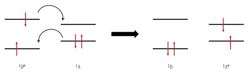
9Figure 2: Schematic representation of the oxidative electron transfer mechanism (top) and the reductive electron transfer mechanism (bottom). Next to an electron transfer, an energy transfer is also a possible deactivation mechanism. In this regard, two different mechanisms have to be considered: the FÖRSTER resonance energy transfer (FRET) (see Figure 3) and the DEXTER energy transfer (see Figure 4). In both cases the energy donor transfers its energy radiationless to the energy acceptor. The energy donor is relaxed to the ground state, while the energy acceptor is excited simultaneously. The FRET mechanism is based on the assumptions that, on one hand, the fluorescence spectrum of the energy donor overlaps with the absorption spectrum of the energy acceptor and, on the other hand, that energy donor and acceptor are coupled by electrostatic dipole-dipole interactions. Therefore, energy can be transferred over relatively large distances of up to 10 nm. 16 Triplet-triplet energy transfer is usually not observed via the FRET mechanism, since the oscillator strength of the absorption from singlet ground states to triplet excited states is too small. 10
Figure 3: Schematic representation of the FÖRSTER resonance energy transfer (FRET) mechanism.

On the other hand, the DEXTER mechanism operates only over short distances of a maximum of 1.5

nm. 16 This is due to an actual electron exchange between energy donor and acceptor, which demands

an orbital overlap. The excited electron of the energy donor is transferred simultaneously to the

LUMO of the energy acceptor, while an electron of the ground state of the energy acceptor is

transferred back to the ground state of the energy donor. FÖRSTER and DEXTER energy transfers

are competitive in terms of singlet-singlet transitions. Since the overall spin of the reacting pair in

the electron exchange is conserved, a triplet-triplet energy transfer is possible via the DEXTER

mechanism. 14,20

Figure 4: Schematic representation of the DEXTER electron exchange mechanism.

                                                                                                    11
4.2 Molecular building blocks
4.2.1 Carbon nanodots
Carbon nanodots (CNDs) are a relatively new class of material with extraordinary properties. They
were first found by Xu et al. in 2004 as a by-product in the production of single-walled carbon
nanotubes (SWCNT) upon arc discharge. 21 CNDs are small, quasi-0-demensional nanoparticles with
sizes typically below 10 nm. They compose mostly of carbon (50 – 80 %), oxygen, nitrogen, and
hydrogen. What draws the attention of researchers up until today is the unique combination of
properties of CNDs. CNDs exhibit a bright and tuneable fluorescence, are easy and cheap to
synthesize, are highly water soluble, are biocompatible and nontoxic, are sensitive to the environment
and excellent electron donors and acceptors. The origin of the fluorescence will be discussed later in
more detail. This combination of properties leads to a whole spectrum of possible applications. CNDs
22 23
can be used as biosensors or nano sensors for metal cations, as drug carriers 24, in the fields of
25
bioimaging or cancer therapy 26, as replacement for toxic metal-based quantum dot emitters 27
or
as photosensitisers in photocatalysis 28. The list goes on and more information can be found in the
literature. 21,27,29,30 However, in the context of this thesis, the most important applications are the use
of CNDs in optoelectronic devices like light emitting diodes (LED) 31, CND-based lasers 32,33
or dye
sensitized solar cells 34.
4.2.1.1 Synthesis
In general, there are two different methods to produce CNDs: the top-down and the bottom-up
approach. Top-down methods describe hereby the disruption of higher ordered carbon materials, like
graphite (bulk), graphene (2D), or carbon nanotubes (1D) to yield the quasi-0-dimensional CNDs.
There are several methods that use the top-down approach:
In the laser ablation method, a solid precursor surface (e.g. graphite) is hit with a pulsed laser beam,
which leads to the ejection of nanoparticles. By changing the laser parameters, the CND
characteristics can be controlled. So, for example Hu et al. found a correlation between pulse duration
and particle sizes due to changes in the conditions of the nucleation and growth processes. 30,35 Other
variable parameters are the laser wavelength, the surrounding medium and the carbon target.
Another possible synthesis route is a redox reaction in an electrochemical cell. Here an electric
current is applied between two electrodes, which are separated by an electrolyte. For example, multi-
1236
walled carbon nanotubes (MWCNT) can be used as working electrode in an acetonitrile solution.
Cycling the electrochemical potential leads to the formation of CNDs, starting at defect sites of the
21
MWCNTs. An important parameter thereby is the presence of an alkaline environment during the
37
synthesis. Other parameters used to control the CND properties are the use of different
21,30
electrolytes and solvents, duration times, or applied potentials. Other frequently used top-down
methods are the previously mentioned arc discharge, which produces a whole variety of CNDs in one
38
step, or acidic oxidation of bulk carbon.
Bottom-up methods describe the carbonization of different molecular precursors to yield CNDs. All
kind of carbon containing molecules can be used as precursor, which leads to a large variety of
different CNDs. Commonly used are glucose, sucrose, or organic acids. The addition of other
39 40
molecular precursors like urea or thiourea can lead to a doping of the CND and can introduce
different functional groups on the CND surface. The most used bottom-up techniques are thermal-
or microwave decomposition. Upon heating in an autoclave or by exposure to microwaves, the partial
carbonization of the molecular precursor in solution is achieved. These methods yield well defined
41
CNDs and are at the same time fast and cost efficient, since even raw materials like grass, fruit
juice 42 or biomass 43 etc. can be used. Another advantage of bottom-up approaches compared to top-
down methods is the lack of the need of further post-synthetic treatment or passivation. The CND
surface produced from most top-down methods usually must be chemically passivated by various
44
polar moieties after the synthesis, in order to get the highly fluorescent CNDs.
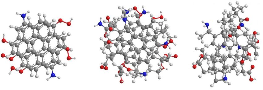
134.2.1.2 Structure
Figure 5: Schematic representation of graphene quantum dots (left), graphitic carbon nano dots
(middle) and amorphous carbon dots (right). Grey dots represent carbon atoms, red dots oxygen,
blue dots nitrogen and white dots hydrogen.
With so many different synthesis methods and parameters that can be tuned, it is possible to
synthesise many CNDs with different properties. In this context, CNDs should be understood as a
relatively wide family of nano systems with several structural sub-types, rather than just a particle
in different sizes. So far there is no classification for CNDs that is generally accepted in the literature.
However, there are three commonly reoccurring sub-types, that are also relevant for this thesis.
These are amorphous CNDs, graphitic CNDs, and graphene quantum dots, which are schematically
represented in Figure 5. In general, CNDs consist of an either graphitic or amorphous core,
surrounded by a surface structure that can host different polar or nonpolar functional groups or even
45
polymer chains. The most common functional groups are carboxyl, carboxylate, hydroxyl, amine,
and amide groups, which is why most CNDs are highly water soluble. The composition of these groups
determines the solubility and has also a huge influence on the emission properties of the CND. Even
though the degree of graphitisation of the CND core may vary, most CNDs in the literature are
30,46,47,48
described as graphitic. This type of CND has a spherical shape and consist of several layers
of sp2-hybridized carbon. The mono-crystalline nature of the core can be visualized by high-
resolution transmission electron microscopy (HRTEM). 47 Sizes range from the size of small molecules
around 1 nm to 50 nm. In general, elucidating the CND structure needs a combination of different
techniques: (HRTEM), 47 atomic force microscopy (AFM), 49 x-ray powder diffraction (XRD), 50 x-ray
photoelectron spectroscopy (XPS), 50 Fourier-transform infrared spectroscopy (FTIR), 50 13C-nuclear
magnetic resonance spectroscopy (13C-NMR), 50 Raman spectroscopy. 51 In contrast to the spherical
14graphitic CNDs, graphene quantum dots possess a disc shape, where 1-3 layers of graphene are
stacked on top of each other. The graphene edges can bear different functional groups. Amorphous
CNDs are spherical and consist of an unordered mixture of sp2- and sp3-hybridized carbons. It must
be mentioned that CNDs must not be entirely either amorphous or graphitic, but can consist of both
parts, e.g., sp2-hybridized carbon islands within an amorphous shell. The part that is dominating the
CND properties is used to classify the material. Another proposed core structure involves the
formation of small molecules during the synthesis, that stack together in the partially carbonized core
via van-der-Waals or π-π interactions. 30 Citrazinic acid, for example, is a molecule that could be
formed during microwave synthesis using the common precursor citric acid.
4.2.1.3 Photophysics
Most CNDs possess diverse absorption features ranging from the ultraviolet region up to 650 nm. In
this regard, the absorption features located in the UV-region are attributed to π-π* transitions of
sp2-hybridized carbons, while absorptions in the visible region are attributed to trap states on the
52
surface.
One of the key features of all CNDs is the bright and tuneable emission. In other words, the emission
maximum shifts with excitation wavelengths. But, despite the great scientific interest in CNDs over
more than 15 years, the mechanism and the origin of this behaviour is still not well understood.
Especially how the emission is linked to the CND structure (surface and core) is still under heavy
debate. Finding an answer to that question is the inevitable next step, in order to apply CNDs in a
broader market. A lot of theories have been proposed over the years. The following section tries to
give an overview about the current state of the art, based mostly on the 2018 review by Sciortino et
al. in the Journal of Carbon Research. 30 Concerning the origin of the emission, several theories exist
in the literature. Some authors link the emission to a quantum confinement effect, hence CNDs are
37,53,54,55
sometimes also called carbon quantum dot (CQD) or graphene quantum dot (GQD). The size
dependence of emission properties is generally a well-known concept observable in inorganic
semiconductor quantum dots. For crystal sizes below the exciton BOHR radius, the emission blue
37,53
shifts with decreasing particle size. This has also been observed for some CNDs and GQDs.
Theoretical simulations suggest that the emission peak depends on the amount of graphene like rings
or the size of sp2-domains. 30,53,54,55
This intrinsic emission, stemming from band-to-band transitions
could not only explain the size dependent emission of graphene flakes in GQDs, but it also links the
15emission of graphitic and amorphous CNDs to sp2-hybridized islands in the CND core. However,
there are some difficulties concerning this interpretation. Some authors found a red-shift of the
emission of some CNDs with decreasing particle sizes, which should not be the case if quantum
56
confinement is the origin of the emission. Additionally theory shows that quantum confinement
could only be responsible for the emission in either ultra-small CNDs or amorphous CNDs with small
sp2-hybridized islands, since the bandgap of π-domains with a diameter of 2 nm is already too small
57
to emit visible light. On top of that, it does not explain why the emission is so sensitive to the
external environment (e.g. metal cations quench CND emission) or why CNDs produced in top-down
methods need further surface passivation in order to become fluorescent. The latter two examples
already hint towards a huge influence of the surface structure on the emission mechanism. Therefore,
53
many authors attribute CND emission to surface defects, surface molecular like states or surface
58
charge traps. It must be mentioned that the CND emission does not exclusively stem from either
the surface or the core. Both parts contribute to the emission and the complex interplay between
both is one of the reasons why the mechanism is still not fully resolved. Wang et al. proposed a
fluorescence mechanism that accommodates the core-surface interplay. The core could act as an
optical antenna, which can be photoexcited. In the next step, the exciton is transferred to the surface
and electron and hole are trapped in surface traps. The emission then stems from the radiative
59
recombination of the trapped charges. Besides that there are still contrasting models. CND
60
emission could also stem from an optical charge transfer transition, from molecular fluorophores
61
like cytrazinic acid attached to the dot, or from the stacking of molecular chromophores in H-
62
aggregates. All these mechanisms are possible, although the unique interplay between different
30
electronic states is structure-dependent and uniquely determined for each sub-type of CND.
Considering the tunability of the emission, most authors hold the structural inhomogeneity of CNDs
responsible. The origin could be the chemical variability of CNDs surface structure or charge from
63 64
dot to dot, the broad distribution of size and shape irregularities, the variability of the density
65
of emitting states on different dots, or the presence of different types of CND aggregates in
66,30
solution However it is still debated whether the tunability is purely an ensemble property or if it
stems from the individual dots. Linking the optical properties of CNDs reliably to the microscopic
structure is still an active body of research.
164.2.2 Transition metal dichalcogenides
Since the first manufacture of graphene by Geim and Novoselov in 2004 67, two dimensional, layered
materials have drawn huge attention in the scientific community as well as in the media. The unique
set of properties of graphene, like extraordinary tensile strength, high thermal conductivity, or the
zero-band gap structure, which renders graphene a semi-metal, have opened many different fields in
which 2-D materials can be applied. But especially in the case of solar energy conversion,
semiconductors with a defined bandgap are more useful than metals. Therefore, there was a need to
develop materials that combine the advantages of 2-D materials, like a large surface area or high in
plane mechanical stability and conductivity with semiconductors. One class of materials that suit
these criteria are transition metal dichalcogenides (TMDs). TMDs in general have the formula MX 2,
where M stands for a transition metal (like Mo, W, Tc, Ti, Ta) and X for a chalcogen atom (S, Se,
68
Te). The metal atom is sandwiched by two chalcogen atoms, leading to a three-atom thick
monolayer. Several monolayers are stacked upon each other by weak VAN-DER-WAALS forces or
π-stacking interactions to yield the bulk material. The most common TMD is molybdenum disulfide
69
(MoS2) due to its natural occurrence in molybdenite ore. In MoS2, the d-orbitals of molybdenum
70
are bound to the p-orbitals of sulphur. MoS2 exists in three different forms: 1T, 2H, and 3R. In
this notation, the number indicates the number of layers and the letter the crystallographic structure
71
(trigonal, hexagonal and rhombohedral).
17Figure 6: Schematic representation of the different MoS2 phases. The brown dots represent the Mo atoms, while yellow dots represent S atoms. The three forms differ in their respective stacking sequences. 1T has a (AbC AbC) stacking sequence, 2H a (AbA BaB) sequence, and 3R a (AbA CaC BcB) sequence, where upper-case letters indicate chalcogen atoms and lower-case letters metal atoms. 72 This difference in the stacking sequence also leads to different properties of the MoS2 forms. So, for example the 2H phase is the thermodynamically most stable one and it possesses semiconducting properties, while the 1T phase is meta stable and metallic. All phases can be transformed into each other, even though the 2H phase is the only stable one at room temperature. Hence the properties of the 2H phase will be discussed in the following pages. 18
Figure 7: Schematic representation of the band structure of bulk MoS2 (left) and single layer MoS2
(right).

One interesting phenomenon in 2-D layered materials is the change of material properties going from

the bulk material to the monolayer. In the case of MoS2, the bulk material possesses an indirect band

gap of 1.2 eV, transitioning from the maximum of the valence band at the Γ point of the BRILLOUIN

zone to the minimum of the conduction band (see Figure 7). Decreasing the number of layers until

the monolayer, results in an increase of the band gap to 1.8 eV. This can be rationalized by the

transition to a direct band gap material, where a direct excitation at the K and K’ points is possible.

The indirect band gap transition is increased due to a quantum confinement effect in the out-of-
                                                                     69
plane direction, when the material is reduced to a few layers.             The direct transition is not affected

by that and hence becomes the minimum energetic band-to-band transition. 73 The reason for this is

that at the K and K’ points, the corresponding valence and conduction band states are only related
                                                                                         74
to the transition metal and, therefore, not affected by interlayer interactions.
                                                     OD a.u.
OD a.u.

          300   400    500      600     700    800             300   400         500      600      700      800

                      Wavelength / nm                                          Wavelength / nm

Figure 8: Absorption spectra of few layer MoS2 (left) and WS2 (right).

                                                                                                             19
The absorption spectrum of MoS2 can be seen in Figure 8. Single layer MoS2 is known for its strong
light matter interaction, which results in an absorption coefficient as high as 106/cm. Hence up to
10 % of irradiated light can be absorbed by a single layer of MoS2. 69 The absorption spectrum consists
of the excitonic transitions of single-layer MoS2 at 670 nm (A-exciton), 610 nm (B-exciton), and
75
around 430 nm (C-exciton). The splitting of the minimum transition at the K and K’ points, is
rationalized by strong spin orbit coupling, which breaks the degeneracy of the valence band. Hence
76
also the optical transition is split into two (A- and B-exciton). Increasing the number of layers
results in a red-shift of the A- and B-excitons as well as a decrease of the energy difference of the
77
peaks, since the splitting of the valence band is reduced. Bulk MoS2 does not show any
photoluminescence due to the indirect transition between conduction and valence band. Single layer
77
MoS2 however, with its direct band gap transition, shows photoluminescence at 627 and 677 nm.
Both, bottom-up and top-down methods exist to yield monolayer MoS2. The most common top-down
78 79
methods are micromechanical cleavage of bulk MoS2 and liquid phase exfoliation. Among the
bottom-up methods, chemical vapor deposition (CVD), 80 plasma enhanced CVD, 81 and atomic layer
81
deposition (ALD) are frequently used.
Tungsten disulfide (WS2) is another TMD that has been used in this thesis (see Figure 8). The
mechanical, electrical, and optical properties are similar to MoS2. Single layer WS2 also possesses a
direct bandgap of 2.1 eV, while the bulk material has an indirect bandgap of 1.3 eV. 82 A strong spin
orbit coupling also gives rise to degenerated valence and conduction bands at the K and K’ points.
However, in WS2, the transition between the uppermost valence sub band and the lowermost
conduction sub band is optically inactive, resulting in one excitonic transition in the absorption
spectrum (A-exciton). 83 In general, TMDs can be applied to many different fields, like gas sensing, 84
85 70
photocatalytic hydrogen production, optoelectric devices, batteries ,86 or photodetectors. 87
204.2.3 Porphyrin
The porphyrin molecule consists of four pyrole rings, which are connected among themselves via
methine bridges as depicted in Figure 9. In general, porphyrins can be divided into two groups, the
free base porphyrins, in which two hydrogen atoms are bound to two opposite nitrogen atoms in the
ring, and the metalloporphyrins, in which the hydrogen atoms are replaced by a central metal cation.
Basically, all kinds of metals can be used to yield a metalloporphyrin with Zn being the most common
one.
Figure 9: Molecular structures of a free base porphyrin (left) and a metalloporphyrin (right). β- and
meso positions are indicated in blue and brown, respectively.
Porphyrins, and especially metalloporphyrins, are one of the most important biomolecules in nature.
The two most important processes where porphyrins are used are probably photosynthesis and
oxygen transport. In photosynthesis, chlorophyll, a Mg-porphyrin, is used as a light harvesting
complex in both the photosystem I (PSI) and the photosystem II (PSII). The energy of light is collected
by several porphyrins and then used in further steps to split water and CO2 and to build
carbohydrates. On the other hand, in haemoglobin and myoglobin in red blood cells, an Fe-porphyrin
is used as reaction centre to bind oxygen and therefore enables the haem proteins to transport
oxygen through the body. 88
There are different ways to synthesize porphyrins. In mammal cells, porphyrins are produced in a
side reaction of the citrate cycle from succinyl-CoA and glycin. The porphyrin is built in a multistep
88
reaction via a linear tetrapyrrole. Synthetically, the ROTHEMUND-reaction, a cyclization of four
89,90
pyrroles and four formaldehydes is a common synthesis route.
21Fluorescence a.u.
Fluorescence a.u.
OD a.u.
OD a.u.
300 400 500 600 700 800 300 400 500 600 700 800
Wavelength / nm Wavelength / nm
Figure 10: Absorption (black) and fluorescence (red) spectra of a free base porphyrin (left) and a Zn-
porphyrin (right).
In Figure 10 the absorption and fluorescence spectra of a free base and a Zn-porphyrin are shown.
The absorption spectrum shows the main absorption at 420 nm, the Soret- or B-band, as well as
bands of significantly lower intensity between 500 and 700 nm, the Q-bands. 91 A porphyrin possesses
22 π-electrons, 18 of which are delocalized in the conjugated macrocycle. Therefore, porphyrin
follows the HÜCKEL-rule (4n+2) and is, hence, aromatic. This is also the reason for the intense
absorption in the visible range of the spectrum. The shape of the spectrum, however, can be
understood by the help of the GOUTERMAN four-orbital-model. The Soret-band corresponds to
symmetry allowed π-π* (S0-S2) transitions and is, hence, more intense than the symmetry forbidden
or quasi-allowed π-π* (S0-S1) transitions of the Q-bands. This model presumes two almost
degenerated HOMO`s and two degenerated LUMO`s, giving rise to two Q-bands (Qx and Qy) in
metalloporphyrins of point group D4h. Free base porphyrins show, however, four Q-bands due to a
92,93
symmetry lowering of the molecule to D2h. The emission also depends strongly on the
configuration of the porphyrin core. A free-base porphyrin possesses a fluorescence that resembles
the mirror image of the lowest energy absorption. The fluorescence quantum yield as well as the
fluorescence lifetime is decreased in metalloporphyrins, since a heavy metal atom supports ISC to
94,95
the triplet excited state and, therefore, facilitates phosphorescence. Another possibility to alter
the spectroscopic properties of porphyrins is via substitution. Substitution is possible at the β- and
the meso-position, even though the effect is typically stronger at the meso-position, since the orbital
density of all four HOMOs and LUMOs is located here. 96 Additionally porphyrins can be substituted
via coordination to the metal centre.
224.2.4 Phthalocyanine
Phthalocyanines are closely related to porphyrins and, hence, exhibit similar properties. They consist
of four aza-bridged isoindole units, as it can be seen in Figure 11. Just like porphyrins,
phthalocyanines are planar and exhibit 18 π-electrons, implying HÜCKEL-aromaticity. A possible
synthesis for metalated phthalocyanines is the condensation of phtalonitril in a basic medium like
97-101
DMAE during the presence of a metal salt.
Figure 11: Molecular structures of a free base phthalocyanine (left) and a metallophthalocyanine
(right).
The electronic spectra of phthalocyanines can also be explained by the four-orbital model of
102
GOUTERMAN (see Figure 12). The addition of benzene rings and aza-nitrogens breaks the
degeneracy of the two HOMOs that was present in porphyrins. This leads to the fact that the Q-
band transitions (S0-S1) between 600 and 700 nm are strongly enhanced, with extinction coefficients
of up to 3x10⁵ M-1 cm-1, compared to the Soret-band (S0-S2) at around 350 nm. While metalated
phthalocyanines show one Q-band, free-base phthalocyanines show a split in the Q-band absorption
due to their lower symmetry. In a free base derivative, two opposing isoindole nitrogens are carrying
hydrogen atoms, whereas the other two are involved in iminic type functions, hence, giving two
103
components of the split band polarized in the x- and y-directions. The position and shape of the
Q-bands are also strongly affected by the solvent, the pH-value, substitution or the central
104,105,106
metal.
23Fluorescence a.u.
OD a.u.
300 400 500 600 700 800
Wavelength / nm
Figure 12: Absorption (black) and fluorescence (red) spectra of Zn-phthalocyanine.
Similarly, to porphyrins, the addition of a central metal with a high atomic number shortens the
fluorescence lifetime and decreases the fluorescence quantum yield. The reason for this is again the
107
intensified ISC due to the heavy atom effect, which yields the excited triplet state. Overall the
fluorescence quantum yields of phthalocyanines are even higher than their porphyrin analogues, which
103
makes phthalocyanines ideal light-harvesting chromophores. Phthalocyanines tend to aggregate
quite strongly and, hence, either suitable substitutions or low concentrations are needed to yield
monomers. Both, H- and J-type aggregates have been reported, with a blue-shifted absorption for
108,109
H-type aggregates and a red-shifted absorption for J-type aggregates.
244.2.5 Rylene diimides
Another important class of chromophores are rylene-dyes, among which naphthalene diimides (NDI)
and perylene diimides (PDI) are the most common ones. Rylene-dyes consist of linearly connected
naphthalene units. In this manner, NDIs are the shortest member of the rylene family, with only one
naphthalene unit, while PDIs possess two, as depicted in Figure 13. Also, higher order rylene-dyes
110
can be synthesized by further increasing the naphthalene chain.
Figure 13: Molecular structures of NDI (left) and PDI (right). The colours indicate the imide- (green),
ortho- (brown) and bay positions (blue).
NDIs and PDIs are planar molecules with a rigid π-conjugated scaffold, hence the absorption maxima
shift barthochromically with increasing chain length. Absorption- and fluorescence spectra of NDI
110
and PDI are shown in Figure 14.
Fluorescence a.u.
Fluorescence a.u.
OD a.u.
OD a.u.
300 400 500 600 700 800 300 400 500 600 700 800
Wavelength / nm Wavelength / nm
Figure 14: Absorption (black) and fluorescence (red) spectra of NDI (left) and PDI (right).
The main absorptions of NDIs are located below 400 nm and attributed to absorptions into different
111
vibronic levels of the first excited state. Monomeric PDIs, typically show an intense absorption
25with a well-defined vibronic fine structure between 400 and 650 nm, with the highest intensity at the
112
lower wavelength region.
Due to the planarity of the molecules PDIs tend to aggregate strongly or even self-assemble into
supra-molecular architectures, which breaks the fine structure.
PDIs possess a fluorescence quantum yield of close to unity, which can be explained, on one hand,
by the planarity and rigidity of the carbon skeleton, which prevents a radiation less deactivation to
the ground state, and on the other hand, by the energetically low-lying triplet level, which renders
the ISC a slow and unlikely process. The quantum yield decreases, however, with increasing
naphthalene chain length due to the increasing probability of radiationless energy relaxation via
113
vibration induced torsion of the naphthalene units.
NDIs on the other side, usually show only a weak fluorescence with quantum yields of < 1 %. This can
114,115
be explained by a fast ISC to the triplet state, which depopulates the S1.
The strong, supramolecular π-stacking interactions of the naphthalene units, lead to a poor
solubility in water and organic solvents, especially for higher order rylenes. This problem can be
overcome by an appropriate functionalization. Rylenes can be functionalized either at the imide-, at
the ortho- or at the bay position, as indicated in Figure 13. Any substituent at the imide nitrogen
atom is electronically disconnected from the perylene diimide core due to nodes in HOMO and LUMO
and hence does not affect the physical properties. 113,116 Hence, a substitution at the imide position
is mainly used to increase the solubility and to prevent aggregation. Substitution at the bay position
has, however, a huge influence on the electronic and optical properties, due to the localization of the
HOMO and LUMO at these positions. Bay substitution can also lead to a twisting of the naphthalene
113,117,118,119
units and hence increase solubility by several orders of magnitude.
NDIs and PDIs are also well known for their highly reversible reductions (-1.0 and -1.2 V vs Fc/Fc+
in dichloromethane) and the high stability of the resulting radical anions and dianions, which makes
them interesting candidates as electron acceptors in electron donor-acceptor systems. 113,120 Besides
that, NDIs and PDIs are highly chemical, thermal, and photochemical stable. The reason for that is,
on the one hand, the electron poorness of the π-conjugated scaffold, which makes it resistive to
oxidative degradation and, on the other hand, the very inefficient triplet formation, since reactions
113,116
from short lived photoexcited singlet states are less likely.
264.2.6 Extended tetrathiafulvalene
P-quinonoid π-extended tetrathiafulvalene (exTTF), as depicted in Figure 15 is a tetrathiafulvalene
(TTF) derivative.
Figure 15: Molecular structure of exTTF.
The addition of an anthracene unit to the two 1,3-dithiole rings, shifts the absorption maximum from
121
around 300 nm for TTF into the visible region up to 450 nm for exTTF. The spectrum consists of
several bands, corresponding to transitions into different singlet excited states, with the main
122
absorption at around 435 nm (see Figure 16).
Fluorescence a.u.
OD a.u.
300 400 500 600 700 800
Wavelength / nm
Figure 16: Absorption (black) and fluorescence (red) spectra of exTTF.
123
exTTF has an out of plane butterfly shape, which prevents aggregation. Probably the most
important property of exTTF is the low-lying oxidation potential of 0.44 V vs SCE in
dichloromethane, which renders exTTF a suitable candidate as an electron donor in electron donor-
27124
acceptor systems for solar energy conversion. Interestingly, exTTF undergoes a two-electron
oxidation to form the dication species, which is extraordinary stable. This long lifetime of a usually
short lived dication can be explained by a geometrical change from the butterfly shape to a planar
structure and from an increase in aromaticity, upon oxidation. Hence, long charge separated state
125
lifetimes in electron donor-acceptor systems can be achieved using exTTF as an electron donor.
The spectroscopic fingerprints of the exTTF dication can be found at 365 and 470 nm, while the less
126
stable monocation is characterized by a maximum at 660 nm.
exTTF fluorescence is located at around 480 nm and rather weak, which can be rationalized by the
short lifetime of the excited state, which, in turn, can be explained by a strong second-order vibronic
127
spin-orbit coupling of the sulphur atoms.
284.2.7 TCAQ
Tetracyano-p-quinodimethane (TCAQ), as depicted in Figure 17, is a well-known electron acceptor
with structural and electrochemical similarities to exTTF. TCAQ can easily be reduced due to its
low reduction potential. Similarly, to exTTF, the butterfly shaped TCAQ gains planarity and
aromaticity upon reduction. The reversible reduction is a two-electron process, resulting in the
radical dianion. The dianion can then undergo a coproportionation reaction with a neutral TCAQ
128
molecule, which leads to two monoanions. However, since aromaticity and planarity are far more
pronounced in the dianion than in the monoanion, the dianion is more stable. Hence, the dianion can
be visualized as an anthracene molecule substituted by two negatively charged dicyanomethyl groups.
129
Even a third and fourth reduction at the anthracene core at lower reduction potentials are possible.
Figure 17: Molecular structure of TCAQ.
29TCAQ does not show absorptions in the visible region, as shown in Figure 18. Instead of that several
bands appear in the UV region below 400 nm, corresponding to the large HOMO-LUMO band gap
130
of 3.6 eV. Fluorescence of TCAQ is typically weak with a large Stokes shift of around 80 nm due
130
to structural rearrangement upon excitation.
Fluorescence a.u.
OD a.u.
300 400 500 600 700 800
Wavelength / nm
Figure 18: Absorption (black) and fluorescence (red) spectra of TCAQ.
305. Objective
In the following, the photophysical analysis of several novel electron donor-acceptor systems is
presented. In the first part, several different carbon nanodots were at the centre of attention, namely
pressure-synthesized carbon nanodots, graphene quantum dots, and nitrogen-doped carbon
nanodots. The use of carbon nanodots as electron acceptors, as well as electron donors is
investigated and different carbon nanodots were compared. Also, non-covalent interactions in the
form of H-bonds were utilized, in order to couple nanodots and chromophores. In addition, the
interactions of chromophores on the surface of a carbon nanodot were explored. Furthermore, the
ratio of interactions between nanodot and chromophore and between chromophore and chromophore
were addressed. In the second part, a photophysical study of two transition metal dichalcogenides,
namely molybdenum disulfide and tungsten disulfide, was conducted. Energy transfer reactions as
well as electron transfer reactions were explored.
31Sie können auch lesen