Typ 2030 Betriebsanleitung Manuel d'utilisation - Operating Instructions - Schubert & Salzer Control Systems
←
→
Transkription von Seiteninhalten
Wenn Ihr Browser die Seite nicht korrekt rendert, bitte, lesen Sie den Inhalt der Seite unten
Betriebsanleitung

                    Operating Instructions

                    Manuel d'utilisation

                      Typ 2030

Version: 05/2020
                        Bunsenstrasse             D-85053 Ingolstadt
M2030-def.doc           Tel: (0841) 9654-0        Fax: (0841) 9654-590
Art.-Nr: 111 2030       www.schubert-salzer.com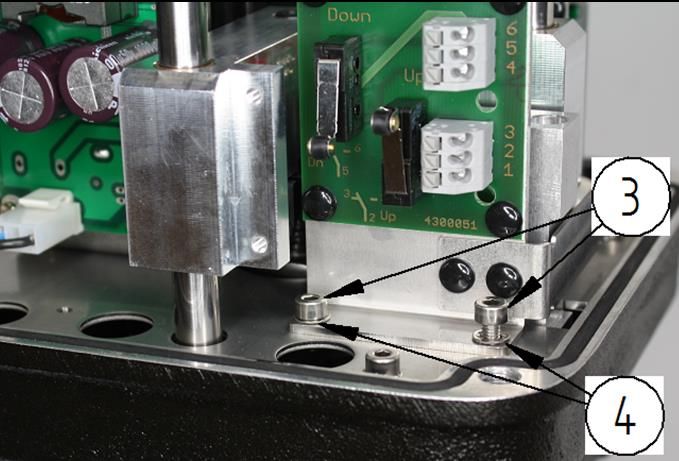
Inhalt/Content/Sommaire

1          Betriebsanleitung (deutsch) ...................................................... 3
    1.1   Technische Daten                                                                  3
    1.2   Einbau                                                                            4
    1.3   Elektrischer Anschluss                                                            5
    1.4   Adaption des Antriebs                                                             12
    1.5   Hand-Betrieb                                                                      13
    1.6   Störmeldeausgang                                                                  15
    1.7   Nachrüsten der Endlagenschalter                                                   17
    1.8   Einstellen der Endlagenschalter                                                   20
    1.9   Kommunikationssoftware                                                            21
2                 Operating Instructions (English) ..................................... 22
    2.1   Technical data                                                                    22
    2.2   Installation                                                                      23
    2.3   Electrical connection                                                             24
    2.4   Adaptation of the actuator                                                        31
    2.5   Manual operation                                                                  32
    2.6   Fault alarm output                                                                34
    2.7   Setting the limit switches                                                        36
    2.8   Communications software                                                           40
3           Instructions de service (français) ........................................... 41
    3.1   Caractéristiques techniques                                                       41
    3.2   pose                                                                              42
    3.3   Raccordement électrique                                                           43
    3.4   Adaptation de l’actionneur                                                        50
    3.5   Mode manuel                                                                       51
    3.6   Sortie de signal d’erreur                                                         53
    3.7   Réglage des interrupteurs de fin de course                                        58
    3.8   Logiciel de communication                                                         59

                                                  -2–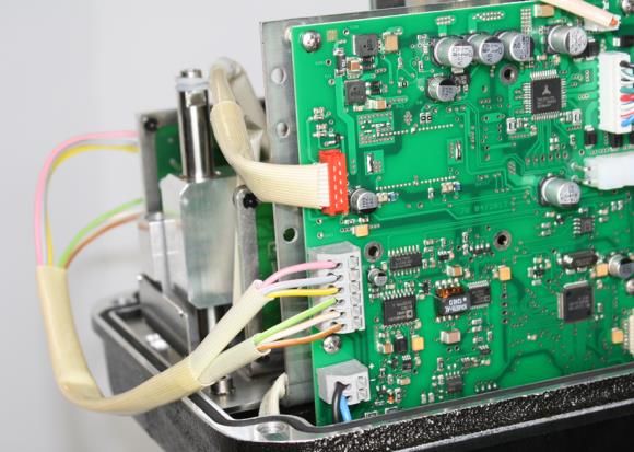
1        Betriebsanleitung (deutsch)

    Technische Daten

Technische Daten des Antriebs mit Positionsregelung

Weitere technische Daten entnehmen Sie bitte den Datenblättern.

                                         -3–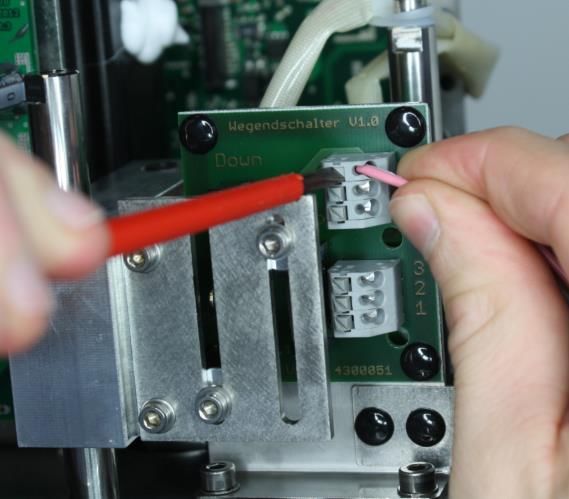
Einbau
Von dem Antrieb sind alle Verpackungsmaterialien zu entfernen.

Die Einbaulage des Motors ist beliebig, mit Ausnahme der Stellung „Haube nach unten“

Die Funktion des kompletten eingebauten Motors ist vor der Inbetriebnahme der Anlage zu
überprüfen.

                                            -4–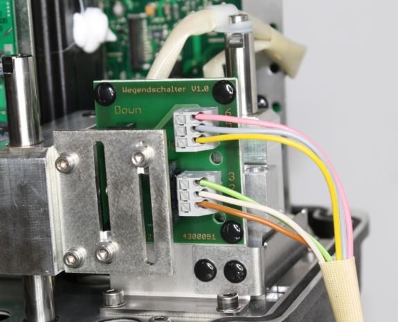
Elektrischer Anschluss
Der elektrische Anschluss erfolgt am integrierten Klemmkasten des Antriebs.

Hier finden Sie auch alle Taster für die Vor-Ort Bedienung und ein LCD Display.

Die Antriebshaube muss nicht abmontiert werden !

                 Der elektrische Anschluss darf nur durch qualifiziertes Personal erfolgen.
                 Beachten Sie unbedingt bei Montage, Inbetriebnahme und Betrieb der
                 Geräte die entsprechenden nationalen Sicherheitsvorschriften (z. B. VDE
                 0100).
                 Alle Arbeiten dürfen nur im spannungslosen Zustand erfolgen.
                 Bei Nichtbeachten der entsprechenden Vorschriften können schwere
                 Körperverletzungen und/oder Sachschäden auftreten.

                                             -5–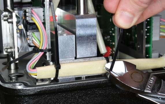
1.3.1 Klemmenbelegung für Antriebe mit Positionselektronik

Die Belegung der Klemmen ist auf einem Schaltplan auf der Rückseite des Deckels für den
Klemmenkasten angegeben. Die Anschlussklemmen sowie die Erdungsklemme sind
entsprechend gekennzeichnet.

       Klemme    Kurzbezeichnung   Funktion
           1     U in              Stellsignaleingang 0(2)-10 V
           2     I in              Stellsignaleingang 0(4)-20mA
           3     0                 Stellsignal (-)
           4     0                 Stellungsrückmeldung (-)
           5     I out             Stellungsrückmeldung 0(4)-20mA
           6     U out             Stellungsrückmeldung 0(2)-10 V
           7     Alarm 1           Alarmausgang 1
           8     Alarm 2           Alarmausgang 2
           9     0                 Alarmausgang COM
          10     Bin in            Binäreingang (+)
          11     Bin 0             Binäreingang (-)
          12     L+                Spannungsversorgung L bei AC, (+) bei DC
          13     N-                Spannungsversorgung N bei AC, (-) bei DC
          14     SW1 NC            Endschalter 1 Öffner
          15     SW1 0             Endschalterb 1 COM
          16     SW1 NO            Endschalter 1 Schließer
          17     SW2 NC            Endschalter 2 Öffner
          18     SW2 0             Endschalterb 2 COM
          19     SW2 NO            Endschalter 2 Schließer
          20     CL                Binäransteuerung Schließrichtung (+)
          21     0                 Binäransteuerung (-)
          22     OP                Binäransteuerung Öffnungsrichtung (+)

                                          -6–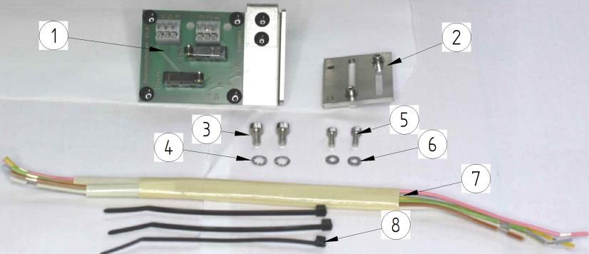
1.3.2 Versorgungsspannung

Die Spannungswerte für die Versorgungsspannung sind dem Typenschild des Antriebs zu
entnehmen.

                Anschluss DC                                     Anschluss AC

                      12 13                                              12 13

             DC (+)            DC (-)                        AC (L)              AC (N)

1.3.3 Stellsignal (Sollwert)

Der Antrieb kann sowohl mit einem Stellsignal als Stromsignal (0/4-20mA) als auch mit einem
Spannungssignal (0/2-10V) betrieben werden.

            Stellsignal (0/4-20mA)                           Stellsignal (0/2-10V)

                 1    2   3                                          1    2   3

                              Signal (-)
                                                            Signal                Signal (-)
                  Signal
                                                           0/2-10V
                0/4-20mA

           Standardsignal: 4-20mA                          Stamndardsignal: 2-10V
      min. Eingangswiderstand 100 Ohm                 min. Eingangswiderstand 60 kOhm

                 Der Signalbereich kann mit der Kommunikationssoftware „DeviceConfig“
                 verändert werden.

                                            -7–
1.3.4 Stellungsrückmeldung (Istwert)

Der Antrieb kann die aktuelle Position des Antriebs sowohl mit einem Stromsignal (0/4-20mA)
als auch mit einem Spannungssignal (0/2-10V) zurückmelden.

      Stellungsrückmeldung (0/4-20mA)                   Stellungsrückmeldung (0/2-10V)

                          4   5   6
                                                                        4   5   6

             Signal (-)
                                                           Signal (-)                Signal
                        Signal                                                      0/2-10V
                      0/4-20mA

          Standardsignal: 4-20mA                             Standardsignal: 2-10V
        max. Lastwiderstand 500Ohm                        min. Lastwiderstand: 5kOhm
              (max. Bürde 10V)

                  Der Signalbereich kann mit der Kommunikationssoftware „DeviceConfig“
                  verändert werden.

1.3.5 Binäreingang

                  Der Binäreingang ist für Sonderfunktionen vorbehalten und in der
                  Standardausführung ohne Funktion.

                                                                  Signal: 24V DC

                                                        (max. Signalbereich 12-30V DC)

                                             -8–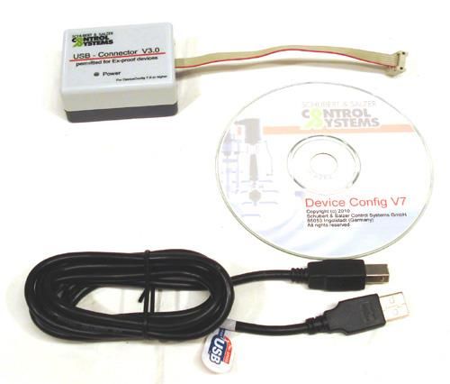
1.3.6 Binäre Ansteuerung (3-Punkt Schritt Regelung)

Der Antrieb kann so konfiguriert werden, dass er mit einem binären Signal (24V DC)
angesteuert werden kann.
Der Antrieb verhält sich dann wie ein Stellantrieb ohne Positionselektronik.

Die zusätzlichen Funktionen der Positionselektronik wie Stellungsrückmeldung, Alarmausgang,
Wartungsdaten, Selbstabgleich usw. können aber auch bei dieser Ansteuerung genutzt werden.

      Ventilspindel fährt aus Antrieb aus:                       Ventil HALT

                                                                 STOP

                 20 21 22                                        20 21 22

    BIN (+)                        BIN (+)           BIN (+)                     BIN (+)

                   BIN (-)                                         BIN (-)

     Ventilspindel fährt in den Antrieb ein:

                                                               Signal: 24V DC
                  20 21 22                              (max. Signalbereich 12-30V DC)

     BIN (+)                       BIN (+)

                    BIN (-)

                 Die Umstellung von analoger Ansteuerung auf Binäre Ansteuerung kann nur
                 mit der Konfigurationssoftware durchgeführt werden.

                                               -9–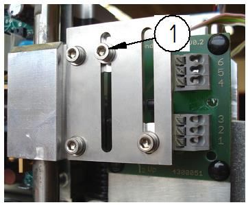
1.3.7 Endlagenschalter (Optional)

Der Antrieb kann mit zwei wegabhängigen Endlagenschaltern ausgerüstet werden.

Beide Endlagenschalter sind als Wechsler ausgeführt.

Die Anschlussklemmen für die Endlagenschalter sind in den Klemmenraum geführt.

Die Klemmen 14-16 sind mit dem unteren Endlagenschalter verbunden, die Klemmen 17-19 mit
dem oberen Endlagenschalter.

                                       Anschluss DC

                                   14 15 16 17 18 19

                                max. 250V AC/DC, max.1A

                Hier angeschlossene Fremdspannungen sind zu kennzeichnen, da diese
                auch bei abgeschalteter Versorgungsspannung anliegen können.

                                           - 10 –
1.3.8 Externes Stromversorgungsmodul (3-Phasen-Wechselstrom)
Für den Betrieb des Motorantriebes mit 3-Phasen-Wechselstrom (2x/3x 400…500V AC)
empfehlen wir die Verwendung eines Stromversorgungsmoduls.
Z.B. Typ TRIO-PS/3AC/24DC/5 von PHOENIX CONTACT.
Das Stromversorgungsmodul wird auf eine Hutschiene im Schaltschrank montiert. Die
Versorgung des el. Antriebes erfolgt dann mit 24V DC. Die Motorspannung ist
dementsprechend zu wählen.
Anschlussschema:
Schaltschrank
Stromversorgungs-
modul
400...500 V AC 24 V DC
L1 24 V DC
L2 +
-
(L3)
- 11 –Adaption des Antriebs
Alle Antriebe sind werkseitig auf die dazugehörige Armatur eingestellt und
geprüft.
Eine Adaption oder Justage ist nicht erforderlich.
Nach Reparatur oder bei Austausch des Antriebs muss jedoch die
Einstellung des Antriebs überprüft und ggf. eine neue Adaption
vorgenommen werden.
Bei der automatischen Adaption wird der eingestellte Hub der Armatur durchfahren.
Dabei werden die ventilspezifischen Parameter gemessen und dauerhaft im Antrieb
gespeichert.
Am Ende der Adaption erfolgt eine Normierung der Soll- und Istwert-Signale auf den
Hubbereich der Armatur
S1 S2
Die beiden Tasten S1 und S2 gleichzeitig für ca. 3
Auto
03 4 %
Sekunden drücken.
S3
LCD
S1 S2 Das Antrieb wechselt vom Automatikbetrieb in den
Adaptionsbetrieb.
ADA
S3
Dies wird im Display angezeigt.
LCD
Der Antrieb durchfährt 1-mal den gesamten Hubbereich
des Ventils.
S1 S2 Nach Ende der Adaption.
Der Antrieb wechselt selbst wieder in den
Automatikbetrieb.
Auto
03 4 %
Der Ventilhub in % wird angezeigt.
S3
LCD
- 12 –Hand-Betrieb
1.5.1 Verfahren mit Handrad
Der Antrieb kann mit dem seitlichen Sterngriff von Hand verstellt werden.
Antriebe mit Positionselektronik können nur mit dem Handrad verfahren
werden, wenn sie nicht unter Spannung stehen und keine Notstellfunktion
integriert ist.
Die Positionselektronik würde den Antrieb immer wieder in seine
Ausgangsstellung zurückfahren.
Ein Verfahren ist dann nur im „MAUELL“-Modus möglich!
Durch Drehen der Handbetätigung im
Urzeigersinn fährt die Spindel in den
Antrieb ein.
Durch Drehen der Handbetätigung gegen
den Urzeigersinn fährt die Spindel aus
dem Antrieb aus.
- 13 –1.5.2 Verfahren im „MANUELL“-Modus
S1 S2
Entweder die Taste S1 oder die Tasten S2 für
ca. 3 Sekunden drücken.
Auto
03 4 %
S3
LCD
Der Antrieb wechselt in den „MANUELL“-Modus
Anzeige mit Symbol im Display
Bei Drücken der Taste S1 fährt die Spindel in
den Antrieb ein.
Die aktuelle Antriebsposition wird angezeigt.
Bei Drücken der Taste S1 fährt die Spindel aus
dem Antrieb aus.
Die aktuelle Antriebsposition wird angezeigt.
S1 S2
Durch gleichzeitiges Drücken beider Taster
wechselt der Antrieb wider in den Automatik-
Auto
03 4 %
Betrieb.
S3
LCD
- 14 –Störmeldeausgang
Bei Auftreten von Störungen werden diese mit einem Code (E01, E02 usw.) auf dem Display
angezeigt und werden an den Sammelstörmeldeausgängen ausgegeben.
Die Störmeldeausgänge schalten eine
angeschlossene Spannung (max. 24V
AC/DC).
Die Polarität ist beliebig.
7 8 9 Er ist mit max. 70 mA belastbar.
(so dass auch z.B. Relais direkt
betrieben werden können)
Alarm 1 Alarm COM Bei induktiven Lasten ist eine
Freilaufdiode vorzusehen.
Alarm 2
Die Bedeutung der Fehlercodes kann der nachfolgenden Tabelle entnommen werden.
Anzeige Fehler Ursache/Behebung
E01 Antrieb ist nicht abgeglichen Abgleich durchführen
Es liegt entweder kein
Stellsignal an, oder das
E02 Sollwertfehler
Stellsignal liegt außerhalb des
gültigen Bereiches
Der Antrieb erreicht nicht
E03 Regelfehler
seine Sollposition
E06 EEPROM Motorantrieb neu starten
Die Versorgungsspannung an
E20 Netzausfall den Klemmen 12, 13 ist
ausgefallen
- 15 –Fail Safe - Funktionsfehler Die Fail Safe Funktion steht
E21 nicht zur Verfügung.
Ursachen:
Serviceschalter ist in
„OFF“ Stellung
Selbsttest der
Elektronik wurde nicht
bestanden
Lebensende der
Kondensatoren ist
erreicht
Fail Safe - Ladevorgang Es ist noch nicht genügend
E22 Energie im Kondensatorpaket
gespeichert um den Antrieb
sicher in die
Sicherheitsstellung zu fahren.
Das Kondensatorpaket wird
aufgeladen.
Anzeige Fehler Ursache/Behebung
E01 Antrieb ist nicht abgeglichen Abgleich durchführen
Es liegt entweder kein
Stellsignal an, oder das
E02 Sollwertfehler
Stellsignal liegt außerhalb des
gültigen Bereiches
Der Antrieb erreicht nicht
E03 Regelfehler
seine Sollposition
In der Grundversion V01.00 werden alle Fehler am Alarmausgang 1
ausgegeben!
- 16 –Nachrüsten der Endlagenschalter
Nachrüstsatz (4 099 014):
(1) 1 x Platine mit Endschaltern
(2) 1 x Blech mit Schaltnocken
(3) 2 x Zylinderschraube M4x8
(4) 2 x Zahnscheibe
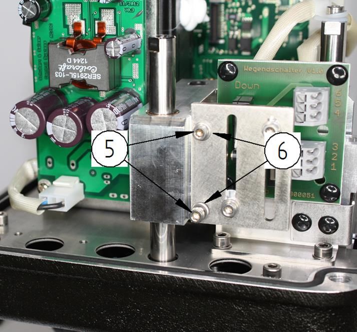
(5) 2 x Zylinderschraube M3x8
(6) 2 x Scheibe
(7) 1 x Kabelbaum
(8) 3 x Kabelbinder
Platine mit Endschaltern (1)
mit 2 x Zylinderschraube (3)
und 2 x Zahnscheiben (4) auf
Grundplatte des Antriebes
schrauben.
Blech mit Schaltnocken (2) mit
2 x Zylinderschraube (5) und
2 x Scheibe (6) auf
Verdrehsicherungsstrebe
schrauben.
- 17 – Kabelbaum (7) an Platine mit
Endschalter anschließen
Öffnen der Klemmen durch
einpressen des Schalters mit
Schraubendreher
Kabelbaum (7) an
Hauptplatine anschließen
rosa
6
Endschalter
grau 6
(down)
5
gelb 5
4
Hauptplatine
Klemmleiste
4
grün 3
3
Endschalter
braun 2
2
(up)
weiß 1
1
- 18 – Sichern des Kabelbaums (7)
mit 3 x Kabelbinder (8)
Einfädeln durch:
2x Nut in Lasche der Platine
mit Endschaltern (1)
1x durch unteres Loch in
Platine mit Endschaltern (1)
Abtrennen der losen
Kabelbinderenden
- 19 –Einstellen der Endlagenschalter
Die Endlagenschalter sind Zubehör und daher in der „Standardausführung“
nicht enthalten!
Einstellen des unteren Endschalters
Ventil in die untere Endlage fahren.
Schraube der Schaltnocke(1) für den
unteren Endschalter lösen
(Innensechskant 3mm).
Schaltnocke von oben kommend so weit
nach unten schieben bis der Endschalter
betätigt wird.
Schaltpunkt an den Klemmen 14-16
kontrollieren.
Schraube der Schaltnocke festziehen.
Einstellen des oberen Endschalters
Ventil in die obere Endlage fahren.
Schraube der Schaltnocke(2) für den
oberen Endschalter lösen
(Innensechskant 3mm).
Schaltnocke von unten kommend so weit
nach oben schieben bis der Endschalter
betätigt wird.
Schaltpunkt an den Klemmen 17-19
kontrollieren.
Schraube der Schaltnocke festziehen.
- 20 –Entsorgung
Das Gerät und die Verpackung müssen entsprechend den einschlägigen Gesetzen und
Vorschriften im jeweiligen Land entsorgt werden.
Kommunikationssoftware
(Optional nur für Antriebe mit Positionselektronik)
Die Einstellung der Funktionsparameter des Antriebs kann über eine PC-Schnittstelle und die
entsprechende Konfigurierungssoftware „DeviceConfig“ ab Version 7.03.00 erfolgen.
Sie wird benötigt, wenn die werksseitigen Einstellungen des Antriebs verändert werden sollen
(z.B. Einrichtung von Split-Range-Betrieb, Signalbereich, Realisierung spezieller Kennlinien).
Für die Inbetriebnahme sowie den Betrieb des Antriebs und auch dessen Justierung nach
einem evtl. Austausch wird sie nicht benötigt, wenn nicht spezielle lokale Einstellungen
gespeichert waren.
LED1 LED2
1 2 3 4 5 6 7 8 9 10 11 S1 S2
DISPLAY
12 13 S3
LCD
PC-COM
14 15 16 17 18 19 20 21 22 LED3
Der Anschluss an einen PC erfolgt über einem speziellen Adapter am Anschluss „PC-COM“ im
Klemmraum des Antriebs.
Software und Adapter können bei Schubert & Salzer Control Systems GmbH bezogen werden.
Die neueste Version von „DeviceConfig“ kann kostenlos auf der Internetseite von Schubert &
Salzer heruntergeladen werden.
Das Standard-Anwenderpasswort ist: „0000“
- 21 –2 Operating Instructions (English)
Technical data
Technical data for the actuator with position control
Further technical data can be found in the data sheets.
- 22 –Installation
Remove all packaging materials from the valve.
Before installation, check the pipework for contamination and impurities and clean if necessary.
The control valve has to be installed in the pipeline in accordance with its direction of flow. The
flow direction is indicated by an arrow on the body.
For sealing, use flange seals complying with DIN EN 1514-1 or ANSI B16.21 for the appropriate
nominal pressure level.
We recommend flange seals made from pure graphite with stainless steel backup.
The mounting position of the valve is optional except for the position where the motor would
hang downwards.
Before starting up the plant, check the operation of the complete installed valve.
- 23 –Electrical connection
The electrical connection is made at the terminal box integral with the actuator.
In it, you will find all buttons needed for local operation as well as an LCD display.
The actuator cap must not be removed !
The electrical installation must only be carried out by qualified personnel.
Please note the applicable national safety regulations for installation,
start-up and operation of the device.
All work has to be carried out isolated from the power supply. Disregarding
the relevant regulations may cause serious physical injuries and/or property
damage.
- 24 –2.3.1 Terminal layout for actuators with position electronics
The layout of the terminals is provided on a circuit diagram on the reverse side of the cover for
the terminal box. The connection terminals and ground terminal are marked accordingly.
Terminal Abbreviation Function
1 U in Set point signal input 0(2)-10 V
2 I in Set point signal input 0(4)-20mA
3 0 Set point signal (-)
4 0 Position feedback (-)
5 I out Position feedback 0(4)-20mA
6 U out Position feedback 0(2)-10 V
7 Alarm 1 Alarm output 1
8 Alarm 2 Alarm output 2
9 0 Alarm output COM
10 Bin in Binary input (+)
11 Bin 0 Binary input (-)
12 L+ Power supply L with AC, (+) with DC
13 N- Power supply N with AC, (-) with DC
14 SW1 NC Limit switch 1 opener
15 SW1 0 Limit switch b 1 COM
16 SW1 NO Limit switch 1 closer
17 SW2 NC Limit switch 2 opener
18 SW2 0 Limit switch b 2 COM
19 SW2 NO Limit switch 2 closer
20 CL Binary actuation of closing direction (+)
21 0 Binary actuation (-)
22 OP Binary actuation of opening direction (+)
- 25 –2.3.2 Supply voltage
The voltage values for the supply voltage can be read off the type plate of the actuator.
DC connection AC connection
12 13 12 13
DC (+) DC (-) AC (L) AC (N)
2.3.3 Control signal (set point)
The actuator can be operated by a set point represented both by a current signal (0/4-20mA) as
well as by a voltage signal (0/2-10V).
Set point (0/4-20mA) Set point (0/2-10V)
1 2 3 1 2 3
Signal (-) Signal (-)
Signal
Signal
0/2-10V
0/4-20mA
Standard signal: 4-20mA Standard signal: 2-10V
min. input resistance 100 Ohm min. input resistance 60 kOhm
The signal range can be changed with the communications software
“DeviceConfig”.
- 26 –2.3.4 Position feedback (actual value)
The actuator can feed back its actual position both by a current signal (0/4-20mA) as well as by
a voltage signal (0/2-10V).
Position feedback (0/4-20mA) Position feedback (0/2-10V)
4 5 6
4 5 6
Signal (-)
Signal (-) Signal
Signal 0/2-10V
0/4-20mA
Standard signal: 4-20mA Standard signal: 2-10V
max. load resistance: 500Ohm min. load resistance: 5kOhm
(max. load 10V)
The signal range can be changed with the communications software
“DeviceConfig”.
2.3.5 Binary input
Binary input is reserved for special functions and does not operate in the
standard version.
Signal: 24V DC
(max. signal range 12-30V DC)
- 27 –2.3.6 Binary activation (3-point step adjustment)
The actuator can be configured such that it can be activated with a binary signal (24V DC).
The actuator then behaves like an actuator without position electronics.
The additional functions of the position electronics such as position feedback, alarm output,
maintenance data, self-alignment, etc., can still be used, however, with this activation.
Valve stem extends out from actuator: Valve STOPS
STOP
20 21 22 20 21 22
BIN (+) BIN (+) BIN (+) BIN (+)
BIN (-) BIN (-)
Valve stem retracts into actuator:
Signal: 24V DC
20 21 22
(max. signal range 12-30V DC)
BIN (+) BIN (+)
BIN (-)
The changeover from analogue to binary activation can only be performed
using the configuration software.
- 28 –2.3.7 Limit switch (optional)
The actuator can be fitted with two stroke-dependent limit switches.
Both limit switches are designed as two-way contacts.
The connection terminals for the limit switches are routed into the terminal compartment.
Terminals 14-16 are connected to the lower limit switch and terminals 17-19 to the upper limit
switch.
DC connection
14 15 16 17 18 19
max. 250V AC/DC, max.1A
Extraneous voltages connected here must be identified since they may be
present even though the mains voltage may be switched off.
- 29 –2.3.8 External power supply module (3-phase alternating current)
We recommend the use of an external power supply module for operating the actuator with 3-
phase alternating current (2x/3x 400…500V AC).
E.G. type TRIO-PS/3AC/24DC/5 of PHOENIX CONTACT.
The power supply module is installed on a top-hat rail inside a cabinet. The output voltage of the
power supply module is 24 V DC. The motor voltage is to be selected accordingly.
Connection scheme:
cabinet
power supply
module
400...500 V AC 24 V DC
L1 24 V DC
L2 +
-
(L3)
- 30 –Adaptation of the actuator
All actuators are set and checked in the factory on the valve to which they
belong.
Adaptation or adjustment is unnecessary.
However, after repair or exchange of the actuator, the setting of the
actuator needs to be checked and a new adaptation undertaken if
necessary.
Automatic adaptation runs through the set stroke of the valve.
In doing so, the parameters specific to the valve are measured and stored permanently in the
actuator.
At the conclusion of the adaptation, the set point and actual value signals are scaled to the
stroke range of the valve
S1 S2
Press both button S1 and S2 simultaneously for approx.
Auto
03 4 %
3 seconds.
S3
LCD
S1 S2 The actuator changes from automatic operation to the
adaptation operation.
ADA
S3 This is shown on the display.
LCD
The valve goes through the complete stroke range of the
valve once.
S1 S2 After completion of the adaptation.
The actuator changes itself back to automatic operation
Auto
03 4 %
again.
The valve stroke is displayed as a %.
S3
LCD
- 31 –Manual operation
2.5.1 Operating the motor using the handwheel
The actuator can be moved by hand using the fluted knob on the side.
Actuator with position electronics can be moved by means of the
handwheel only if it is not under power and has no safety reset
incorporated.
The position electronics would always return the actuator to its starting
position.
Therefore, operating is only possible in the “MANUAL” mode!
By turning the knob in the clockwise
direction, the stem retracts into the
actuator.
By turning the knob in the anticlockwise
direction, the stem extends out of the
actuator.
- 32 –2.5.2 Operation in the “MANUAL” mode
S1 S2
Press either button S1 or button S2 for approx.
3 seconds.
Auto
03 4 %
S3
LCD
The actuator changes to the “MANUAL” mode
Shown with symbol in the display
When button S1 is pressed, the stem retracts
into the actuator.
The present position of the actuator is
displayed.
When button S2 is pressed, the stem extends
out from the actuator.
The present position of the actuator is
displayed.
S1 S2
By pressing both buttons simultaneously, the
actuator changes back to automatic operation.
Auto
03 4 %
S3
LCD
- 33 –Fault alarm output
When faults occur, they are shown on the display with a code (E01, E02, etc.) and are issued
at the combined fault alarm outputs.
The fault alarm outputs switch on a
connected voltage (max. 24V AC/DC).
The polarity is optional.
Max. 70 mA are applied
7 8 9
(so that relays, for example, can be
operated directly)
In the case of inductive loads, a free-
Alarm 1 Alarm COM wheeling diode needs to be provided.
Alarm 2
The meaning of the fault codes can be seen in the following table.
Display Fault Cause/solution
E01 Actuator is not aligned Perform alignment
There is either no set point
E02 Set point fault signal, or the set point is
outside the valid range
The actuator is not reaching
E03 Control fault
its set point position
E06 EEPROM Restart motorised actuation
Electrical supply to terminals
E20 Power failure
12, 13 has failed
Fail safe function not available
Causes:
Service switch is in
“OFF” position
E21 Fail safe function fault Self test of electronics
not passed
Capacitors have
reached end of service
life
- 34 –Insufficient energy stored in
capacitor pack to run the
E22 Fail safe charging process actuation safely to the safety
position.
Capacitor pack is recharging.
Display Fault Cause/solution
E01 Actuator is not aligned Perform alignment
There is either no set point
E02 Set point fault signal, or the set point is
outside the valid range
The actuator is not reaching
E03 Control fault
its set point position
In the basic version V01.00, all faults are issued at alarm output 1!
- 35 –retrofitting of limit switches
retrofit kit (4 099 014):
(1) 1 x board with limit switches
(2) 1 x sheet with switching cams
(3) 2 x cheese head screw M4x8
(4) 2 x lock washer
(5) 2 x cheese head screw M3x8
(6) 2 x washer
(7) 1 x wire harness
(8) 3 x cable tie
screw board with limit switches
(1)with 2x cheese head screw
(3) and 2x lock washer (4) on
base plate of actuator
screw sheet with switching
cams (2) with 2x cheese head
screw (5) and 2x (washer (6)
on anti twist bar
- 36 – connect wire harness (7) to
bard with limit switches
open clips by pressing the
switch with a screwdriver
connect wire harness (7) to
main board
pink
6
limitswitch
grey 6
(down)
5
yellow 5
terminal strip
4
main board
4
3 green 3
limitswitch
2 brown 2
(up)
1 white 1
- 37 – secure wire harness (7) with
3x cable tie (8)
thread through:
2x notch in strap of the board
with limit switches (1)
1x through hole in board with
limit swiches (1)
cut off the loose ends of the
cable ties (8)
- 38 –Setting the limit switches
The limit switches are accessories and are not included, therefore, in the
“standard version”!
Setting the lower limit switch
Run valve to the lower end position.
Loosen the screw holding the switching
cam(1) for the lower limit switch (3mm
hexagon socket).
Push switching cam downwards until it
operates the limit switch.
Check the switching point at terminals
14-16.
Tighten the screw holding the switching
cam.
Setting the upper limit switch
Run valve to the upper end position.
Loosen the screw holding the switching
cam(2) for the upper limit switch (3mm
hexagon socket).
Push switching cam upwards until it
operates the limit switch.
Check the switching point at terminals
17-19.
Tighten the screw holding the switching
cam.
- 39 –Communications software
(Optional only for actuators with position electronics)
Setting the function parameters of the actuator can be performed via a PC interface using the
corresponding “DeviceConfig” configuration software from Version 7.03.00 onwards.
It is needed if the factory settings of the actuator have to be changed (e.g. setting up split range
operation, signal range, achieving special characteristics).
It is not needed for starting up or operation of the actuator or even after adjusting it after it may
have been exchanged, if no special local setting had been stored.
LED1 LED2
1 2 3 4 5 6 7 8 9 10 11 S1 S2
DISPLAY
12 13 S3
LCD
PC-COM
14 15 16 17 18 19 20 21 22 LED3
The connection to a PC is made by using a special adaptor at the “PC-COM” connection in the
terminal compartment of the actuator.
The software and adaptor can be obtained from Schubert & Salzer Control Systems GmbH. The
latest version of “DeviceConfig“ can be downloaded without charge on Schubert & Salzer’s
Website.
The standard user password is: “0000”
- 40 –3 Instructions de service (français)
Caractéristiques techniques
Caractéristiques techniques de l’actionneur à régulation
Pour les autres caractéristiques techniques, veuiller vous reporter aux fiches
signalétiques.
- 41 –pose
Déballer entièrement la vanne.
Avant la pose, vérifier que la canalisation est propre et ne contient pas de corps étrangers, et la
nettoyer si nécessaire.
Poser la vanne de régulation dans la canalisation conformément au sens d’écoulement. Celui-ci
est indiqué par une flèche sur le corps.
Pour les garnitures d’étanchéité de bride, utiliser des joints DIN EN 1514-1 ou ANSI B16.21
dans le palier de pression nominale correspondant.
Nous recommandons des garnitures d’étanchéité de bride en graphite pur et acier spécial.
La vanne peut être montée dans n’importe quelle position, sauf « tête en bas ».
Vérifier le fonctionnement de la vanne avant de mettre l’installation en service.
- 42 –Raccordement électrique
Procéder au raccordement électrique au boîtier de connexions intégré à l’actionneur.
Vous y trouverez également toutes les touches permettant la commande sur place et un écran
LCD.
Le capot de l’actionneur ne doit pas être démonté !
Le raccordement électrique doit impérativement être confié à un
personnel qualifié.
Les prescriptions de sécurité nationales (par ex. VDE 0100) doivent
également être respectées pour le montage, la mise en service et
l’exploitation des appareils.
Tous les travaux doivent être effectués hors tension.
Le non-respect des prescriptions peut entraîner de graves blessures et/ou
dommages matériels.
- 43 –3.3.1 Occupation des bornes des actionneurs à régulation électronique
L’occupation des bornes est indiquée sur un plan de connexions sur l’envers du couvercle de la
boîte de bornes. Les bornes de raccordement et la borne de mise à la terre sont marquées en
conséquence.
Borne Désignation Fonction
1 U in Signal d'entrée 0(2)-10 V
2 I in Signal d'entrée 0(4)-20mA
3 0 Signal d'entrée (-)
4 0 Signal de recopie (-)
5 I out Signal de recopie 0(4)-20mA
6 U out Signal de recopie 0(2)-10 V
7 Alarm 1 Sortie d'alarme 1
8 Alarm 2 Sortie d'alarme 2
9 0 Sortie d'alarme COM
10 Bin in Entrée binaire (+)
11 Bin 0 Entrée binaire (-)
12 L+ Alimentation L pour CA, (+) pour CC
13 N- Alimentation N pour CA, (-) pour CC
14 SW1 NC Interrupteur de fin de course 1 à ouverture
15 SW1 0 Interrupteur de fin de course 1 COM
16 SW1 NO Interrupteur de fin de course 1 à fermeture
17 SW2 NC Interrupteur de fin de course 2 à ouverture
18 SW2 0 Interrupteur de fin de course 2 COM
19 SW2 NO Interrupteur de fin de course 2 à fermeture
20 CL Commande binaire sens de fermeture (+)
21 0 Commande binaire (-)
22 OP Commande binaire sens d'ouverture (+)
- 44 –3.3.2 Tension d’alimentation
Les valeurs de tension pour l’alimentation sont indiquées sur la plaque signalétique de
l’actionneur.
Raccordement CC Raccordement CA
12 13 12 13
DC (+) DC (-) AC (L) AC (N)
3.3.3 Signal de pilotage (valeur de consigne)
L’actionneur peut être utilisé avec un signal de pilotage comme signal de courant (0/4-20mA) ou
avec un signal de tension (0/2-10V).
Signal de pilotage (0/4-20mA) Signal de pilotage (0/2-10V)
1 2 3 1 2 3
Signal (-)
Signal Signal (-)
Signal 0/2-10V
0/4-20mA
Signal standard : 4-20mA Signal standard : 2-10V
Résistance d’entrée mini. 100 Ω Résistance d’entrée mini. 60 kΩ
La plage du signal peut être modifiée à l’aide du logiciel de communication
« DeviceConfig ».
- 45 –3.3.4 Signal de recopie de position (valeur réelle)
L’actionneur peut confirmer sa position actuelle avec un signal de courant (0/4-20mA) et un
signal de tension (0/2-10V).
Recopie de position (0/4-20mA) Recopie de position (0/2-10V)
4 5 6
4 5 6
Signal (-)
Signal (-) Signal
Signal 0/2-10V
0/4-20mA
Signal standard : 4-20mA Signal standard : 2-10V
Résistance de charge maxi. 500 Ω Résistance de charge mini : 5 kΩ
(charge maxi. 10 V)
La plage du signal peut être modifiée à l’aide du logiciel de communication
« DeviceConfig ».
3.3.5 Entrée binaire
L’entrée binaire est réservée aux fonctions spéciales et ne possède aucune
fonction dans la version standard.
Signal : 24V CC
(Plage de signal maxi. 12-30V CC)
- 46 –3.3.6 Commande binaire (régulation par paliers à 3 positions)
L’actionneur peut être configuré de manière à pouvoir être commandé par un signal binaire
(24V CC).
Il se comporte alors comme un servomoteur sans régulation électronique.
Les fonctions supplémentaires du système de positionnement électronique, comme le recopie
de position, la sortie d’alarme, les données de maintenance, l’équilibrage automatique etc. sont
également disponibles avec cette commande.
La tige de manœuvre sort de l'actionneur : Vanne ARRÊT
STOP
20 21 22 20 21 22
BIN (+) BIN (+) BIN (+) BIN (+)
BIN (-) BIN (-)
La tige de manœuvre rentre dans l’actionneur :
Signal : 24V CC
20 21 22 (Plage de signal maxi. 12-30V CC)
BIN (+) BIN (+)
BIN (-)
La commutation de la commande analogique à la commande binaire peut
uniquement être effectuée à l’aide du logiciel de configuration.
- 47 –3.3.7 Interrupteurs de fin de course (option)
L’actionneur peut être équipé de deux interrupteurs de fin de course asservis à la course.
Les deux interrupteurs de fin de course sont des inverseurs.
Les bornes de raccordement des interrupteurs de fin de course sont logées dans le
compartiment des bornes.
Les bornes 14-16 sont reliées à l’interrupteur de fin de course inférieur, les bornes 17-19 à
l’interrupteur de fin de course supérieur.
Raccordement CC
14 15 16 17 18 19
maxi. 250V CA/CC, maxi.1A
Les tensions d’origine extérieure raccordées ici doivent être signalisées,
car elles peuvent rester actives même lorsque la tension d’alimentation
est coupée.
- 48 –3.3.8 Module d´alimentation électrique (courant alternatif triphasé)
Nous vous recommandons l´utilisation d´un module d´alimentation électrique (comme par
exemple le type TRIO-PS/3AC/24DC/5 de PHOENIX CONTACT) pour l´opération d´un moteur
électrique triphasé (2x/3x 400…500V AC).
Ce module d´alimentation électrique sera monté sur un profilé chapeau dans un armoire de
distribution. L´alimentation de l´actionneur électrique est effectué avec une tension de 24V DC.
La tension du moteur doit être sélectionnée par conséquent.
Schéma électrique:
armoire de distriararmoire de distribution
module
d'alimentation
électrique
400...500 V AC 24 V DC
L1 24 V DC
L2 +
-
(L3)
- 49 –Adaptation de l’actionneur
Tous les actionneurs sont réglés et testés en usine pour la robinetterie
correspondante.
Toute adaptation ou réglage est inutile.
Le réglage de l’actionneur doit être vérifié et, au besoin, ajusté après une
réparation ou un échange de l’actionneur.
L’adaptation automatique consiste à parcourir la course réglée.
Les paramètres spécifiques à la vanne sont alors mesurés et enregistrés dans l’actionneur.
Après l’adaptation, les signaux des valeurs de consigne et réelles sont normés sur la course de
la vanne.
S1 S2
Appuyer simultanément sur les deux touches S1 et S2
pendant env. 3 secondes.
Auto
03 4 %
S3
LCD
S1 S2 L’actionneur passe du mode automatique au mode
adaptation.
ADA Un message correspondant s’affiche sur l’écran.
S3
LCD
L’actionneur parcourt une fois l’intégralité de la course
de la vanne.
S1 S2
Après la fin de l’adaptation :
L’actionneur repasse en mode automatique.
Auto
03 4 %
La course de la vanne s’affiche en %.
S3
LCD
- 50 –Mode manuel
Commande manuelle
L’actionneur peut être actionné manuellement à l’aide de la poignée latérale.
Les actionneurs avec positionnement électronique ne peuvent être
actionnés qu’avec le volant quand ils ne sont pas sous tension et
qu’aucune fonction de positionnement d’urgence n’est intégrée.
Sinon, le système de positionnement électronique ramènerait en
permanence l’actionneur dans sa position d’origine.
L’actionnement n’est alors possible qu’en mode « MANUEL » !
Tourner la poignée dans le sens des
aiguilles d’une montre pour faire entrer la
tige dans l’actionneur.
Tourner la poignée dans le sens inverse
des aiguilles d’une montre pour faire sortir
la tige de l’actionneur.
- 51 –3.5.1 Actionnement en mode « MANUEL »
S1 S2
Appuyer pendant env. 3 secondes sur la touche
S1 ou les touches S2.
Auto
03 4 %
S3
LCD
L’actionneur passe en mode « MANUEL ».
Affichage sur l’écran avec symbole
Lorsque l’on appuie sur la touche S1, la tige
rentre dans l’actionneur.
La position actuelle de l'actionneur s'affiche.
Lorsque l’on appuie sur la touche S2, la tige
ressort de l’actionneur.
La position actuelle de l'actionneur s'affiche.
S1 S2
Lorsque l’on appuie simultanément sur les deux
touches, l’actionneur repasse en mode
Auto
03 4 %
automatique.
S3
LCD
- 52 –Sortie de signal d’erreur
En cas d’apparition de perturbations, celles-ci sont signalisées sur l’écran par le biais d’un code
(E01, E02 etc.) et transmises aux sorties de signalement d’anomalies cumulées.
Les sorties de signalement d'anomalies
commutent une tension raccordée
(maxi. 24V CA/CC).
La polarité peut être choisie
indifféremment.
7 8 9 Le système peut être chargé avec maxi.
70 mA.
(de manière, par exemple, à pouvoir
Alarm 1 Alarm COM faire fonctionner des relais)
Alarm 2 Pour les charges inductives, prévoir une
diode de marche à vide.
La signification des codes d’erreur est indiquée dans le tableau ci-dessous.
Affichage Erreur Cause/Élimination
E01 L’actionneur n’a pas été réglé Procéder à l'équilibrage
Aucun signal de réglage, ou
E02 Erreur de valeur de consigne signal de réglage en-dehors
de la plage admissible
L’actionneur n’atteint pas sa
E03 Erreur de régulation
position de consigne.
Redémarrer l’actionneur
E06 EEPROM
motorisé
Panne de tension
E20 Panne de courant d’alimentation aux bornes 12
et 13
La fonction Fail Safe n’est pas
disponible.
Causes :
Le commutateur de
Fail Safe – Erreur service est sur « OFF »
E21 fonctionnelle Le test automatique de
l’électronique a échoué
Les condensateurs
sont arrivés en fin de
vie
- 53 –La quantité d’énergie dans le
paquet de condensateurs est
encore insuffisante pour
garantir le déplacement de
E22 Fail Safe – Chargement l'actionneur en position de
sécurité.
Le paquet de condensateurs
est en cours de
rechargement.
Affichage Erreur Cause/Élimination
E01 L’actionneur n’a pas été réglé Procéder à l'équilibrage
Aucun signal de réglage, ou
E02 Erreur de valeur de consigne signal de réglage en-dehors
de la plage admissible
L’actionneur n’atteint pas sa
E03 Erreur de régulation
position de consigne.
Dans la version de base V01.00, tous les défauts sont transmis à la sortie
d’alarme 1 !
- 54 –compléter avec fins de courses
kit de modification (4 099 014):
(1) 1 x platine avec fins de courses
(2) 1 x tôle avec cames de contact
(3) 2 x vis cylindrique M4x8
(4) 2 x disque denté
(5) 2 x vis cylindrique M3x8
(6) 2 x rondelle
(7) 1 x faisceau électrique
(8) 3 x attache-câbles
visser la platine avec les fins
de course (1) sur le plateau de
base de l´actionneur avec 2x
vis cylindrique (3) et 2x
rondelles (4).
visser le tôle avec les cames
de contact (2) sur le doigt anti-
inversion avec 2x vis
cylindrique (5) et 2x rondelles
(6).
- 55 – connecter le faisceau
électrique (7) à la platine avec
les fins de course
ouvrir les bornes en pressant
l´interrupteur avec un tournevis
connecter le faisceau
électrique (7) à la platine
principale
rose
6
auxiliaires
6
contact
gris
borne de raccordement
(down)
5
jaune 5
4
carte mère
4
vert 3
3
auxiliaires
2
contact
marron
2
(up)
blanc 1
1
- 56 – fixer le faisceau électrique
avec 3x attaches-câbles
enfiler par:
2x rainure dans la patte de la
platine avec les fins de
course (1)
1x au travers le trou inférieur
de la platine avec les fins de
course (1)
couper les bouts des attaches-
câbles restants
- 57 –Réglage des interrupteurs de fin de course
Les interrupteurs de fin de course font partie des accessoires et ne sont
donc pas inclus dans la « version standard ».
Réglage de l’interrupteur de fin de course
inférieur
Positionner la vanne en position finale
inférieure.
Desserrer la vis de la came de
commutation (1) de l’interrupteur de fin
de course inférieur (vise à six pans
creux de 3 mm).
En partant du haut, pousser la came de
commutation vers le bas jusqu’à ce que
l’interrupteur de fin de course soit
actionné.
Contrôler le point de commutation sur
les bornes 14-16.
Serrer la vis de la came de
commutation.
Réglage de l’interrupteur de fin de course
supérieur
Positionner la vanne en position finale
supérieure.
Desserrer la vis de la came de
commutation (2) de l’interrupteur de fin
de course supérieur (vise à six pans
creux de 3 mm).
En partant du bas, pousser la came de
commutation vers le haut jusqu’à ce que
l’interrupteur de fin de course soit
actionné.
Contrôler le point de commutation sur
les bornes 17-19.
Serrer la vis de la came de
commutation.
- 58 –Logiciel de communication
(en option uniquement pour les actionneurs à régulation électronique)
Les paramètres fonctionnels de l'actionneur peuvent être réglés à l’aide d’une interface PC et
du logiciel de configuration spécifique « DeviceConfig » à partir de la version 7.03.00.
Ce réglage est nécessaire pour toute modification des réglages usine de l’actionneur (par ex.
réglage d’un mode split-range, réalisation de courbes caractéristiques spéciales).
Il n’est pas nécessaire pour la mise en service et l’exploitation de l’actionneur et son réglage
après un éventuel remplacement, sauf si des réglages locaux avaient été enregistrés.
LED1 LED2
1 2 3 4 5 6 7 8 9 10 11 S1 S2
DISPLAY
12 13 S3
LCD
PC-COM
14 15 16 17 18 19 20 21 22 LED3
Le raccordement à un PC s’effectue par le biais d’un adaptateur spécial sur la prise « PC-
COM » dans le compartiment des bornes de l’actionneur.
Le logiciel et l’adaptateur peuvent être commandés auprès de Schubert & Salzer Control
Systems GmbH. La dernière version de « DeviceConfig » peut être téléchargée gratuitement
sur le site internet de Schubert & Salzer.
Le mot de passe standard est : « 0000 »
- 59 –Original Schubert & Salzer Produkte werden ausgeliefert über:
- 60 –Sie können auch lesen