Typ 4037 Betriebsanleitung Manuel d'utilisation - Operating Instructions - Schubert & Salzer
←
→
Transkription von Seiteninhalten
Wenn Ihr Browser die Seite nicht korrekt rendert, bitte, lesen Sie den Inhalt der Seite unten
Betriebsanleitung

                    Operating Instructions

                    Manuel d'utilisation

                      Typ 4037

Version: 02/2021
                        Bunsenstrasse             D-85053 Ingolstadt
M4037-def.doc           Tel: (0841) 9654-0        Fax: (0841) 9654-590
Art.-Nr: 110 4037       www.schubert-salzer.com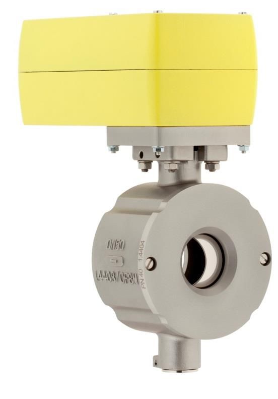
Inhalt/Content/Sommaire

1           Betriebsanleitung (deutsch) ...................................................... 4
    1.1    Ersatzteilliste                                                                   4
    1.2    Technische Daten                                                                  5
    1.3    Allgemeine Beschreibung                                                           6
    1.4    Einbau                                                                            7
    1.5    Technische Daten Antrieb                                                          8
    1.6    Antriebsversionen                                                                 8
    1.7    Hand-Notbetätigung                                                                8
    1.8    El. Anschlussplan                                                                 8
    1.9    Adaption                                                                          13
    1.10   Endschalterbox                                                                    15
    1.11   Klemmkasten                                                                       17
    1.12   Explosionsschutz nach ATEX 2014/34/EU                                             18
    1.13   Auswechseln der Sitzdichtung                                                      19
    1.14   Demontage des kompletten Ventils                                                  21
    1.15   Entsorgung                                                                        26
    1.16   Montage des Ventils                                                               26
    1.17   Montagewerkzeuge                                                                  32
    1.18   Schmier- und Klebeplan                                                            33
2                  Operating Instructions (English) ..................................... 34
    2.1    Spare parts list                                                                  34
    2.2    Technical data                                                                    35
    2.3    General description                                                               36
    2.4    Installation                                                                      37
    2.5    Technical Data of the Actuator                                                    38
    2.6    Actuator versions                                                                 39
    2.7    Manual Override                                                                   39
    2.8    El. Connection                                                                    40
    2.9    Self adjustment                                                                   44
    2.10   Switch box                                                                        46
    2.11   Connection box                                                                    48
    2.12   Explosion protection according to ATEX 2014/34/EU                                 49
    2.13   Exchanging the seat seal                                                          50
    2.14   Dismantling the complete valve                                                    52
    2.15   Assembling the valve                                                              57
    2.16   Assembly tools                                                                    63
    2.17   Lubrication and bonding plan                                                      64
3            Instructions de service (français) ........................................... 65
    3.1    Liste des pièces de rechange                                                      65
    3.2    Caractéristiques techniques                                                       66
    3.3    Description générale                                                              67
    3.4    Pose                                                                              68
    3.5    Informations techniques de l’actionnement                                         68
    3.6    Versions des actionneurs                                                          68
    3.7    Actionnement d’urgence à la main                                                  69
    3.8    Raccordement électrique                                                           69
    3.9    Self adaption                                                                     74
    3.10   Switch box                                                                        76
                                                -2-
3.11   Connection box                                     78
3.12   Protection antidéflagrante selon ATEX 2014/34/UE   79
3.13   Remplacement du joint de siège                     80
3.14   Démontage de la vanne complète                     82
3.15   Montage de la vanne                                87
3.16   Outils de montage                                  93
3.17   Plan de graissage et de collage                    94

                                         -3-
1        Betriebsanleitung (deutsch)
1.1      Ersatzteilliste

      (Nur Original Ersatzteile von Schubert & Salzer Control Systems verwenden!)

                                            -4-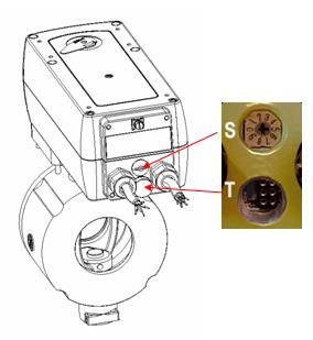
1.2          Technische Daten

Bauform                                         Zwischenflansch-Ausführung
Nennweiten                                      DN 25 bis DN 100
Gehäusewerkstoff           Gussteile            1.4408 (CF8M)
                           Drehteile            1.4404 (316L)
Lagerwerkstoff                                  Hochtemperatur Gleitlager (Iglidur Z)

Nenndruck                  DN 25 - DN 50        PN40 (für Flansche PN 10 - PN 40), ANSI300, ANSI150

                           DN 80 – DN 100       PN25 (für Flansche PN 10 - PN 25), ANSI150
Medientemperatur                                -60°C bis + 220°C            je nach Dichtungsausführung
Umgebungstemperatur                             -40°C bis + 50°C
Kennlinie                                       Annähernd gleichprozentige Ventilkennlinie
Stellverhältnis                                 100:1

    DN            Kvs    Bohrung   Drehwinkel        max.         max.
                           mm       nominal        Druckstufe   Druckstufe
                                                      DIN         ANSI
 25-50%           12,5     15            65°         PN40       ANSI 300
    25            21       19            90°         PN40       ANSI 300
 40-50%           34       25            60°         PN40       ANSI 300
    40            64       32            90°         PN40       ANSI 300
    50            94       40            90°         PN40       ANSI 300
    80            255      64            90°         PN25       ANSI 150
   100            390      80            90°         PN25       ANSI 150

  Sitzring    Kugelsektor                           Leckrate                                 min. Temp [°C]*
                                                         -7
   PTFE       Edelstahl poliert                     5x10 vom max. Kvs                        -60 bis +170°C
   PEEK       Edelstahl poliert                     5x10⁻⁷ vom max. Kvs                      -60 bis +220°C

   PTFE       Edelstahl, hartverchromt              5x10⁻⁷ vom max. Kvs                       -60 bis +170°C
   PEEK       Edelstahl, hartverchromt              5x10⁻⁷ vom max. Kvs                       -60 bis +220°C

                                                    Class IV-S1 nach EN 1349 (IEC 534-4)
   Stellit    Edelstahl, hartverchromt + geläppt                                              -60 bis +220°C
                                                    5x10⁻⁶ vom max. Kvs
   PTFE       Edelstahl, hartverchromt + geläppt    Class VI nach EN 1349 (IEC 534-4)         -60 bis +170°C

* Einschränkungen durch O-Ring Werkstoff beachten !

Weiter technische Daten entnehmen Sie bitten den Datenblättern.

                                                        -5-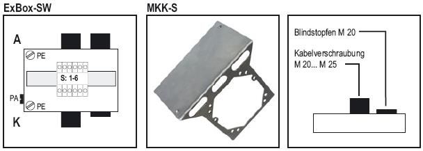
1.3 Allgemeine Beschreibung
Das Kugelsektorventil Typ 4037 besteht aus einer Kugelhalbschale, dem "Kugelsektor", der mit
zwei Lagerzapfen im Ventilgehäuse gelagert ist. Ein Teil des Kugelsektors dient zum
dichtenden Abschluss, der andere Teil hat eine kreisrunde Öffnung, die normalerweise ca. 80%
der Ventilnennweite entspricht.
Der Antrieb des Ventils ist ohne zusätzliche elektronische Hilfsmittel vor Ort einstellbar. Das
Universal selbstadaptive Netzteil erlaubt Versorgungsspannungen von 24 bis 230 V AC/DC. Die
Anbindung des Antriebs auf das Ventilunterteil erfolgt durch eine Adapterplatte. Die
Kraftübertragung erfolgt über einen formschlüssigen Vierkantanschluss. Der Antrieb ist 100%
Blockierfest und Sebsthemmend. Das Gehäuse besteht aus einem robusten Aluminium
Druckguss (optional aus Edelstahl oder mit Amercoatlackierung). Die ATEX Versionen variieren
nach TYP A oder B (Kapitel 1.6). Für nicht explosionsgefährdete Bereiche steht ein Antrieb Typ
C zur Verfügung. Die Federrückstellung erfolgt bei Unterbrechung der Versorgungsspannung.
Die Antriebe sind wartungsfrei. Die druckfeste Kapselung ist durch das Umgehäuse des
Antriebs vor mechanischer Stoßenergie gemäß EN 50014 (Abschnitt 23.4.3.1) geschützt. Es
sind alle nationalen und internationalen Normen und Vorschriften für Ex-Bereiche zu beachten.
Als Zubehör steht eine Endschalterbox mit zwei EEx-d Endschaltern sowie ein EEx-e
Klemmkasten zur Auswahl.
Der mögliche mechanische Drehwinkel ist bei allen Ventilen 90°. Dieser Winkel darf nicht
überfahren werden, da sonst ein Schaden der Sitzdichtung nicht ausgeschlossen werden kann.
Das Kugelsektorventil Typ 4037 ist vorwiegend für eine stufenlose Regelung geeignet, kann
jedoch auch für eine Zweipunkt- (AUF/ZU-) Regelung und auch als Absperrventil eingesetzt
werden.
Die in dieser Betriebsanleitung enthaltenen Daten zum Antrieb sind lediglich ein Auszug aus der
technischen Anleitung des Antriebsherstellers. Weitere Informationen können den
Herstellerdatenblättern entnommen werden.
Antriebshersteller: Schischek GmbH Explosionsschutz
Mühlsteig 45, Gewerbegebiet Süd 5
90579 Langenzenn
Deutschland
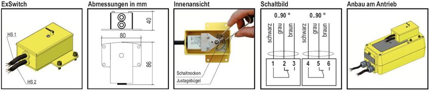
Kennzeichnung
Ventilnennweite, Druckstufe und Gehäusewerkstoff können an Hand der Kennzeichnung am
Gehäuse(1) bzw. am Haltering(2) gemäß nachstehendem Beispiel identifiziert werden:
PN 25 = Nenndruck PN
→ = normale Durchflussrichtung
DN 80 = Nennweite DN
1.4408/CF8M = Gehäusewerkstoff
Zusätzlich befinden sich auf dem Gehäuse und dem Haltering noch die Chargennummer und
die Herstellerkennzeichnung.
-6-
Grenzen für Druck und Temperatur

Die Materialkombination (Sitz und Abdichtung) des Ventils muss für den Anwendungsfall
geeignet sein.

Der zugelassene Druck- und Temperaturbereich ist in den Datenblättern beschrieben. Die
maximalen Betriebs- und Steuerdrücke dürfen nicht überschritten werden.
Für Temperaturen >120°C ist die Druck/Temperaturabhängigkeit in Abhängigkeit vom
Gehäusewerkstoff zu berücksichtigen.

Alle Kugelsektorventile Typ 4037 entsprechen den Anforderungen gemäß Druckgeräte-
Richtlinie 97/23 EG
Angewendete Konformitätsbewertungsverfahren: Anhang II der Druckgeräte-Richtlinie 97/23
EG, Kategorie II, Modul A1
Name der benannten Stelle: TÜV Süddeutschland
Kenn-Nr. der benannten Stelle: 0036

1.4       Einbau
Von der Armatur sind alle Verpackungsmaterialien zu entfernen.

Vor dem Einbau ist die Rohrleitung auf Verunreinigung und Fremdkörper zu untersuchen und
ggf. zu reinigen.

Das Stellventil ist entsprechend der Durchflussrichtung in die Rohrleitung einzubauen. Die
Durchflussrichtung ist am Gehäuse durch einen Pfeil angegeben.

Als Flanschdichtungen sind Dichtungen nach DIN EN 1514-1 bzw. ANSI B16.21 in der
jeweiligen Nenndruckstufe zu verwenden.

Wir empfehlen Flanschdichtungen aus Reingraphit mit Edelstahleinlage.

Die Funktion der kompletten eingebauten Armatur ist vor der Inbetriebnahme der Anlage zu
überprüfen.

                 Wird das Ventil außerhalb der Rohrleitung betätigt, so sind die Einlass- und
                 die Auslassöffnung durch geeignete Schutzvorrichtungen abzudecken.
                 Achtung: Extreme Verletzungsgefahr !!!

Bei einer Verwendung im Freien ist ein Wetterschutzdach (optionales Zubehör) zu verwenden.
Des Weiteren sind die Klemmen 1 und 2 der Versorgungsleitung anzuschließen um eine
Funktion der integrierten Heizung zu gewährleisten.

                                              -7-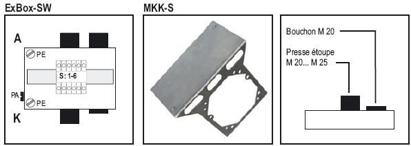
1.5           Technische Daten Antrieb

Versorgungsspannung                      24 … 230 V AC/DC
Schutzart                                IP 66
Stellsignal                              4-20 mA or 0-10 V
Rückmeldesignal                          4-20 mA or 0-10 V
Ex-Schutz (Gas) Typ A                    II 2G Ex d [ia] IIC T6, T5
Ex-Schutz (Staub) Typ A                  II 2D Ex tD [iaD] A21 IP66 T80, T95

Umgebungstemperatur                      T5: -40°C bis 40°C
                                         T6: -40°C bis 50°C
Motor                                    bürstenloser DC Motor
Wartung                                  wartungsarmer Motor
Kabeldurchmesser                         ~Ø7,1 mm und ~Ø7,4mm - 1m Kabel
Umkehrfunktion                           Brücke zwischen Klemme 3 und 4
Halteleistung                            20 W (~16 W im Heizbetrieb)
Stromaufnahme bei
                                         2A
Initialisierung

1.6           Antriebsversionen

        Ex-Schutz (Gas)                          II 2G Ex d [ia] IIC T6, T5                     Zone 1 und 2
Typ A                                                                                           Zone 21 und
        Ex-Schutz (Staub)                        II 2D Ex tD [iaD] A21 IP66 T80, T95°C
                                                                                                22
        Ex-Schutz (Gas)                          II3G Ex nC II T6 / II3(1)G Ex nC [ia] IIC T6   Zone 2
Typ B
      Ex-Schutz (Staub)                          II3D Ex tD A22 IP66 T80°C                      Zone 22
      Industrielle Anwendungen ohne Ex
Typ C                                                                         keine
      Zulassung

1.7           Hand-Notbetätigung
Zur Handnotbetätigung ist ein Sechskantschlüssel beigestellt. Achtung langsam drehen, die
Betätigung kann schwergängig sein.

                    Bei Antrieben mit Federrücklauf besteht Verletzungsgefahr beim loslassen
                    oder lösen des Sechskantschlüssels.

1.8           El. Anschlussplan
Die Antriebe verfügen über eine automatische Erkennung der Spannungsversorgung und
müssen nicht eingestellt werden.
Der Antrieb verfügt über zwei Kabel Ø7,1 (bzw. Ø7,4) und Ø7,4 mm mit je 1 m Länge.
Ein Kabel A (4/5 adrig) dient zur Versorgung, ein weiteres Kabel B bei Regelantrieben (6 adrig)
zur Ansteuerung und Rückmeldung (optional bei Auf/Zu Antrieben für integrierte Hilfsschalter).
Ex Geräte dürfen nur vom Hersteller geöffnet werden.
                                              -8-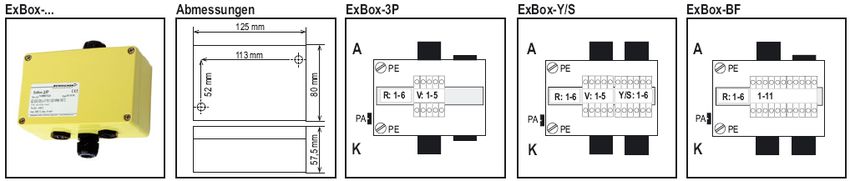
Zusätzlich zum el. Anschluss ist die äußere PA-Anschlussklemme zum Potentialausgleich
anzuschließen.
Die Anschlussleitungen sind fest und so zu verlegen, dass sie vor mechanischer und
thermischer Beschädigung geschützt sind.

                Bei der Inbetrieb- und Ausserbetriebnahme sind die Ex-Schutzvorschriften
                zu beachten. Vor Öffnen des Ex-Klemmkastens ist die
                Versorgungsspannung abzuschalten.

                Antrieb mit Federrücklauf dürfen nicht ohne externe Last betrieben werden.

                Der el. Anschluss ist nur von qualifizierten Fachkräften auszuführen. Beim
                Anschluss im Ex-Bereich ist ein zugelassener EEX-e Klemmkasten
                erforderlich (optionales Zubehör)!

Die Klemme 5 der Versorgungsleitung zum Umschalten der Federrücklaufzeit ist nur bei
Antrieben der Nennweite DN25 vorhanden.

1.8.1    Regelantriebe

Schaltbild 1: DN25 bis DN100 ohne Federrücklauf

                                            -9-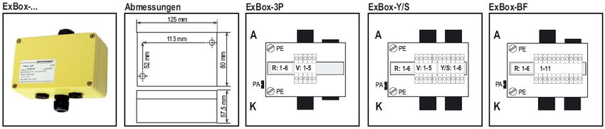
Schaltbild 2: DN25 bis DN80 mit Federrücklauf

Weitere Anschlussmöglichkeiten bei jedem Regelantrieb:

Brücke I:             Umkehrung der Regelung und Rücksendesignal (Invertierung)
Brücke 2 nach 5:      Federrückstellzeit 3 Sek (10 Sek. Standard, nur bei DN25)
Spannung an A:        Antrieb schließt (Zwangssteuerung)
Spannung an B:        Antrieb öffnet (Zwangssteuerung)

                   Beim Anschluss einer Brücke von Klemme 2 nach 5 ist ein Selbstabgleich
                   durchzuführen und die Einschaltdauer von 10% ED einzuhalten! Die
                   Antriebe dürfen nicht ohne externe Last betrieben werden.

1.8.2    Auf/Zu Antrieb mit 3 Punkt Ansteuerung
Zum Schutz von Antriebskomponenten gestattet die Elektronik Impulse > 0,1 Sek mit einer
Pulslänge von 0,5 Sek. Bei einem Richtungswechsel ist eine Pause von 1 Sek einzuhalten.

                                             - 10 -
Schaltbild 3: DN25 bis DN100 ohne Federrücklauf
Schaltbild 4: DN25 bis DN80 mit Federrücklauf
Brücke 2 nach 5: Federrückstellzeit 3 Sek (10 Sek. Standard, nur bei DN25)
Beim Anschluss einer Brücke von Klemme 2 nach 5 ist ein Selbstabgleich
durchzuführen und die Einschaltdauer von 10% ED einzuhalten! Die
Antriebe dürfen nicht ohne externe Last betrieben werden. Der Antrieb im 3
Sek Modus darf nur mit einer Auf/Zu Funktion pro Min betrieben werden, da
sonst die Elektronik überhitzt.
- 11 -Schaltbild 5: DN25 bis DN80 mit/ohne Federrücklauf mit integrierten Hilfsschalter
(Option) und DN100 ohne Federrücklauf
Schaltbild 6: DN25 bis DN80 mit Federrücklauf und 2-Punkt Ansteuerung
Bei einer 2-Punkt Ansteuerung ist die Heizung bei Unterbrechung inaktiv.
Weitere Schaltbilder können dem Herstellerdatenblatt entnommen werden.
- 12 -1.9 Adaption
1.9.1 Stellzeit und Nennstrom
Die Einstellung der Stellzeit und des Drehmoments erfolg am 10-stufigen Drehschalter S auf
der Antriebsrückseite. Eine Einstellung des Schalters (S) ist bei nicht angelegter
Spannungsversorgung oder im Stillstand durchzuführen. Schalter (S) und Taster (T) befinden
sich unter einem Blindstopfen. Diese müssen vor der Adaptierung entfernt werden. Durch
entfernen dieser Blindstopfen verliert der Antrieb nicht den Ex-Schutz. Die Blindstopfen müssen
allerdings nach der Adaption wieder montiert werden um den IP Schutz gewährleisten zu
können. Der Schalter ist mit einem kleinen Schraubenzieher zu stellen. Zu starkes Drücken
oder Drehen kann die Elektronik irreversibel schädigen.
Einstellung des Drehschalters S:
DN25-DN50 DN25 (mit Federrücklauf)
Drehschalter Motordreh- Nennstrom Motordreh- Nennstrom
Rotationszeit Rotationszeit
einstellung moment 24V 230V moment 24V 230V
4,7
0 3/7,5 Sek/90° 4,7 A 0,5 A 3/7,5 Sek/90° 0,5 A
A
1,45
1 15 Sek/90° 1,45 A 0,3 A 15 Sek/90° 0,3 A
A
0,52 0,15
2 30 Sek/90° 15 Nm 0,52 A 0,15 A 30 Sek/90°
A A
0,4
3 60 Sek/90° 0,4 A 0,1 A 60 Sek/90° 0,1 A
A
0,4
4 120 Sek/90° 0,4 A 0,1 A 120 Sek/90° 0,1 A
A
15 Nm
4,7
5 7,5 Sek/90° 4,7 A 0,5 A 7,5 Sek/90° 0,5 A
A
1,45
15 Sek/90° 1,45 A 0,3 A 15 Sek/90° 0,3 A
6 A
0,52 0,15
30 Sek/90° 30 Nm 0,52 A 0,15 A 30 Sek/90°
7 A A
0,4
60 Sek/90° 0,4 A 0,1 A 60 Sek/90° 0,1 A
8 A
0,4
9 120 Sek/90° 0,4 A 0,1 A 120 Sek/90° 0,1 A
A
Federrücklauf ca. 3 oder 10 Sek/90°
- 13 -DN40/50/80 (mit Federrücklauf) DN80 - DN100
Nennstrom Nennstrom
Drehschalter Motordreh- Motordreh-
Rotationszeit Rotationszeit 24
einstellung moment 24V 230V moment 230V
V
1,0
0 40 Sek/90° 2,0 A 0,4 A 40 Sek/90° 0,3 A
A
0,7
1 60 Sek/90° 1,8 A 0,3 A 60 Sek/90° 0,2 A
A
0,5
2 90 Sek/90° 1,4 A 0,15 A 90 Sek/90° 50 Nm 0,15 A
A
0,4
3 120 Sek/90° 1,4 A 0,1 A 120 Sek/90° 0,1 A
A
0,4
4 150 Sek/90° 30 Nm 1,4 A 0,1 A 150 Sek/90° 0,1 A
A
(50Nm
1,0
5 40 Sek/90° DN80) 2,0 A 0,4 A 40 Sek/90° 0,3 A
A
0,7
60 Sek/90° 1,8 A 0,3 A 60 Sek/90° 0,2 A
6 A
0,5
90 Sek/90° 1,4 A 0,15 A 90 Sek/90° 75 Nm 0,15 A
7 A
0,4
120 Sek/90° 1,4 A 0,1 A 120 Sek/90° 0,1 A
8 A
0,4
9 150 Sek/90° 1,4 A 0,1 A 150 Sek/90° 0,1 A
A
Federrücklauf ca. 20 Sek/90°
Die Federrücklaufzeit kann bei der Nennweite DN25 durch Anlegen einer Brücke von Klemme 2
zu Klemme 5 (Schaltbild 2) auf 3 Sek. reduziert werden.
Obenstehende Werte sind cirka Werte, da es innerhalb der Elektronik Bauteilstreuungen gibt.
1.9.2 Selbstadaption
Der Antrieb ist werksseitig auf das Ventil adaptiert.
Vorgehensweise zur Selbstadaption:
• Schalter (S) in Stellung 2 oder 7 stellen
• Taster T für 3 Sek. gedrückt halten
• Antrieb fährt vollen Hub ab selbstständig, dabei blinkt die LED grün
• Nach 60 Sek. ist die Adaption abgeschlossen, die LED leuchtet grün
• Schalter (S) in gewünschte Stellung drehen
1.9.3 Umstellung von stetiger Ansteuerung auf 3-Punkt Ansteuerung
Alle Regelantriebe können von einer stetigen Ansteuerung auf eine 3-Punkt Ansteuerung
umgestellt werden. Dabei bleibt die Rückmeldung von 4-20mA und 0-10V erhalten.
Vorgehensweise:
• Taster (T) 3x kurz drücken (min. 0,2 Sek drücken; Alle 3 Drückvorgänge innerhalb 5 Sek
abarbeiten)
• Die LED schaltet von Dauer Grün auf Dauer Gelb
Zum umstellen von einer 3-Punkt Ansteuerung auf eine steige Ansteuerung ist die
Vorgehensweise zu wiederholen. Die LED schaltet von Dauer Gelb auf Dauer Grün.
Der Antrieb darf nur mit einer Auf/Zu Funktion pro Minute betrieben werden.
Anschluss nach Schaltbild 3 oder 4.
- 14 -1.9.4 LED Signale
Dauer Grün: Antrieb arbeitet ordnungsgemäß
Dauer Gelb: Ein Regelantrieb mit stetiger Ansteuerung wird in der 3-Punkt Ansteuerung
betrieben.
Dauer Rot: Umgebungstemperatur zu hoch
Grün blinkend: Selbstadaption läuft.
Rot blinkend: Antrieb wurden bei einer Temperatur unter -20°C angeschlossen. LED
blinkt rot bis der Antrieb auf -20°C aufgeheizt ist.
1.9.5 Lagerung des Ventils
Das Ventil ist trocken (Feuchte nach EN60335-1) in einem Temperaturbereich von -40 bis
+70°C zu lagern.
1.10 Endschalterbox
1.10.1 Beschreibung
Die Endschalterbox umfasst zwei potenzialfreie Endschalter in einem Gehäuse, die unabhängig
voneinander eingestellt werden können. Eine Einstellung ist während des Betriebs möglich. Die
Schalter sind mit einem 1m langen Kabel ausgeliefert und müssen an einem EEx-e
Klemmkasten angeschlossen werden.
1.10.2 Einstellung
• Das 4-Kant Verbindungsstück in die Antriebsachse des Antriebs legen
• Endschalterbox aufstecken und mit dem beiliegenden 4 Schrauben mit dem Antrieb
verbinden
• Die beiden Hilfsschalter (HS) el. anschließen (EEx-e Klemmkasten erforderlich)
• Antrieb auf Anschlag fahren
• Deckel öffnen und mit dem beigestellten Einstellbügel jeden Schalter separat auf den
gewünschten Schaltpunkt justieren. Hierzu Feststellschraube lockern und mit dem Bügel
die Schaltnocken verstellen, anschließend die Schraube wieder festziehen.
• Testlauf
• Deckel schließen.
- 15 -Montage auf Seite L
0°-5° HS2 auf 85°-90° HS1 auf
Montage auf Seite R
0°-5° HS1 auf 85°-90° HS2 auf
1.10.3 Explosionsschutz
Einsatz in Zone 1 und 2: II2G Ex d IIC T6
Einsatz in Zone 21 und 22: II2D IP66 T80°C
Schutzart: IP66
1.10.4 Technische Daten
Schaltleistung 24V AC/DC, 3A 240V AC, 0,5A
Mech. Lebensdauer 2 Mio Schaltspiele
Umgebungstemperatur -40 bis +40°C
Gehäuse Stahl lackiert (optional Marinelackierung
„Amercoat“)
Gehäuse Schalter Kunststoff
- 16 -1.11 Klemmkasten
1.11.1 Beschreibung
K: Anschluss kundenseitig
A: Anschluss antriebsseitig
V: Klemmen für Versorgung / Auf-Zu / 3-Punkt Ansteuerung
Y: Klemmen für Stellsignal und Rückmeldung
S: Klemmen zum Anschluss von internen Hilfsschaltern
R: Klemmen zum Anschluss der Endschalterbox
Der Klemmkasten ist speziell für Antriebe und Zubehör vom Typ 4037 ausgelegt. Die
Stellantriebe und die Endschalter werden mit einem 1m langen Kabel ausgeliefert. Sofern der
Anschluss im explosionsgefährdeten Bereich erfolgt, ist die Versorgungsspannung und der
Strom vor Öffnen des Klemmkastens abgeschaltet werden.
1.11.2 Explosionsschutz
Einsatz in Zone 1, 2, 21, 22: II2G/2D EEx e II T6
Schutzart: IP66
Potentialausgleich: über äußere PA-Anschlussklemme
- 17 -1.12 Explosionsschutz nach ATEX 2014/34/EU
WARNUNG
Die in diesem Kapitel aufgeführten Hinweise zum Betrieb der Armatur in
explosionsgefährdeten Bereichen sind zwingend zu beachten!
Das Ventil Typ 4037 wurde nach der ATEX-Richtlinie einer Zündgefahrenbewertung für
nichtelektrische Geräte unterzogen. Daraus ergibt sich die folgende Kennzeichnung
II 2G Ex h IIC T6…T2 X Gb
II 2D Ex h IIIC 85°C…220°C X Db
Aus dieser Kennzeichnung ergeben sich Unterschiede in den einzelnen Varianten, die für einen
sicheren Betrieb in einer explosionsgefährdeten Atmosphäre zu beachten sind.
Grenzen des Betriebsbereichs
• Die zu erwartende Oberflächentemperatur des Ventils ist von der Medientemperatur
abhängig und kann maximal die Medientemperatur erreichen.
• Die maximal erlaubte Medientemperatur ist von der der Ventilausführung abhängig und
ist dem Datenblatt zu entnehmen.
• Bei Schaltfrequenzen von mehr als 0,5 Hz ist eine zusätzliche Erwärmung des Antriebs
um 10K über die Medientemperatur zu berücksichtigen. Schaltfrequenzen von über 2 Hz
sind in explosionsgefährdeten Bereichen nicht zulässig.
Die Zuordnung der Temperaturklassen zur maximalen Oberflächentemperatur erfolgt nach DIN
EN ISO 80079-36 6,2,5 Tabelle 2:
Temperaturklasse Maximale Oberflächentemperatur
T1 ≤ 450°C
T2 ≤ 300°C
T3 ≤ 200°C
T4 ≤ 135°C
T5 ≤ 100°C
T6 ≤ 85°C
Die Kennzeichnung gilt für alle Ventile der aufgeführten Baureihe inklusive Antrieb jedoch nur in
den Standard-Ausführungen, die in den Datenblättern aufgeführt sind. Sonderausführungen und
andere Antriebe müssen einer eigenen Konformitätsbewertung nach ATEX unterzogen werden.
Alle elektrischen und mechanischen Zubehörteile (z.B. Stellungsregler,
Grenzsignalgeber, Magnetventile usw.) müssen einer eigenen Konformitätsbewertung
nach ATEX unterzogen werden.
Im Zweifel wird angeraten, der Hersteller zu kontaktieren.
- 18 -1.13 Auswechseln der Sitzdichtung
11
✓ Zylinderschrauben (11) am Haltering
ausschrauben.
10
15 2
✓ Haltering (2) entfernen.
✓ Sitzring (10) und O-Ring (15)
ausbauen.
7 ✓ Stützring (7) entfernen.
16 (Stützring nur bei DN50- DN250)
✓ O-Ring (16) entfernen.
Anmerkung: Der O-Ring (16) ist ab
Nennweite DN150 im Haltering (2)
eingebaut.
✓ Ventil und Haltering (2) reinigen und auf
Beschädigungen untersuchen.
Nur Original Ersatzteile von Schubert &
Salzer Control Systems verwenden!
- 19 -7
✓ Stützring (7) in das Gehäuse einlegen.
(Stützring nur bei DN50- DN100)
Anmerkung:
Der Kugelsektor muss einen
gleichmäßigen Abstand zum Haltering
haben. Bei Bedarf den Kugelsektor
ausrichten.
16 10
15 2
✓ O-Ring (16) montieren.
✓ O-Ring (15) und Sitzring (10) in den
Haltering (2) einlegen.
✓ Kompletten Haltering auf das Gehäuse
aufsetzen.
11
✓ Haltering (2) mit den Schrauben (11)
befestigen.
- 20 -1.14 Demontage des kompletten Ventils
✓ Vor der Demontage des Ventils alle
elektrischen Verbindungen trennen.
✓ Demontage nicht im
explosionsgefährdeten Bereich
durchführen
✓ Bei federbelasteten Antrieben
sicherstellen, dass sich der Antrieb in
der Sicherheitsstellung befindet.
Verletzungsgefahr !
✓ Elektrische Verbindungen zum Antrieb
entfernen.
✓ Schrauben M4x100 (bzw. M8x140)
lösen (bei einer Wetterschutzhabe sind
die Muttern M4 bzw. M8 zu lösen und
die Haue zu entfernen)
✓ Antrieb abnehmen
- 21 -Komponenten 45 und 46 entfallen
bei DN25 und DN40/50 ohne
Federrückstellung.
✓ Schrauben (41), Scheiben (42) und
Muttern (44) lösen und entfernen
✓ Adapterplatte (43), Anschlag (45) mit
Kerbstift (46) entfernen
✓ Ggf. Vierkanthülse(n) (47) entfernen
10
15 2
✓ Haltering (2) entfernen.
✓ Sitzring (10) und O-Ring (15)
ausbauen.
7
16
✓ Stützring (7) entfernen.
(Stützring nur bei DN50- DN100)
✓ O-Ring (16) entfernen.
- 22 -21
✓ Vor Entfernen der Lager müssen
unbedingt die Gewindestifte (21) am
3 Kugelsektor (3) gelöst werden.
Anmerkung: Es ist ausreichend, wenn
die Gewindestifte um ca. 3
Umdrehungen ausgedreht werden.
21
12
✓ Die Spiralstifte (12) mit einem
Durchschlagstift aus dem Gehäuse
herausdrücken.
Anmerkung:
Durchmesser der Spiralstifte:
DN25-DN50: ø4 mm
12 DN80-DN100: ø5 mm
- 23 -T4 ✓ Stift-Auszieher (Tool-T4) in den obern
Lagerzapfen (40) eindrehen.
✓ Durch Schläge mit der Schwungmasse
den Lagerzapfen und die Lagerbuchse
aus dem Ventil herausziehen.
40
6
Achtung:
Bitte Achten Sie darauf, dass der
Kugelsektor nicht die Innenseite des
Gehäuses berührt.
-> Gefahr der Beschädigung !!!
T4
✓ Lagerzapfen (40) und Lagerbuchse (4)
entnehmen.
640
✓ Passfeder (8) entfernen.
4
8
✓ Werkzeug (Tool-T4) entfernen und den
gleichen Demontagevorgang mit der
zweiten Lagerseite durchführen.
- 24 -✓ Lagerzapfen (5) und Lagerbuchse (4)
entnehmen.
8 5
✓ Passfeder (8) entfernen.
4
1
3
✓ Kugelsektor (3) vorsichtig aus dem
Gehäuse (1) nehmen.
13
13 14 14
✓ O-Ringe (13) und (14) vom
Lagerzapfen (5 und 40) und der
Lagerbuchse (4) entfernen.
5
4
640
T3 4 9
PRESS ✓ Beide Gleitlager (9) aus der
Lagerbuchse (4) mit dem Auspressdorn
(Tool-T3) herausdrücken.
- 25 -1.15 Entsorgung
Das Gerät und die Verpackung müssen entsprechend den einschlägigen Gesetzen und
Vorschriften im jeweiligen Land entsorgt werden.
1.16 Montage des Ventils
Wichtig!
Der Kugelsektor der Ventile Typ 4037 ist selbstzentrierend und soll nicht axial im Gehäuse
verschoben werden.
Bei der Montage des Antriebs ist deshalb unbedingt darauf zu achten, dass auf den
Lagerzapfen (40) keine axialen Kräfte wirken, da sonst der Sitzring (10) oder andere Teile
beschädigt werden. Unzulässig ist, mit Hammerschlägen den Lagerzapfen mit der Kupplung
und/oder mit der Bohrung des Antriebes zu verbinden.
Für die Stellung von AUF bis ZU darf der Kugelsektor keinesfalls über den zulässigen
Drehwinkel von 90° gefahren werden. Der Kugelsektor hat ohne Antrieb keine
Drehwinkelbegrenzung.
Die optimale Dichtheit bei Stellung ZU wird nur erreicht, wenn der Sitzring (10) gegenüber der
Kugelsektoroberfläche zentriert ist.
Bei Stellung AUF muss die Kugelsektoröffnung und der Durchgang im Haltering (2)
deckungsgleich sein.
Die Montage sollte nicht im explosionsgefährdeten Bereich durchgeführt werden.
Schmier- und Klebeplan beachten!
Nur Original Ersatzteile von Schubert & Salzer Control Systems verwenden!
✓ Alle Teile Reinigen und nach
Beschädigungen untersuchen
✓ Beschädigte Teile austauschen.
- 26 -4
9 2x ✓ Mit Hilfe des Montagedorns (Tool-T1)
nacheinander beide Gleitlager (9) in
T1 die Lagerbuchse (4) einpressen.
PRESS Anmerkung:
Montagedorn (T1) immer bis zum
Anschlag einpressen.
4
T1
14 ✓ Montagedorn (Tool-T1) in die
Lagerbuchse (4) einschieben.
✓ O-Ringe (14) einfetten.
✓ O-Ringe (14) nacheinander über den
Montagedorn in die Nuten der
Lagerbuchsen schieben.
✓ O-Ringe 13 einfetten.
✓ Montagehülse (Tool- T2) auf die eine
5 Seite des Lagerzapfens (5 und 40)
T2 aufstecken.
640
13 ✓ O-Ring (13) auf die erste Nut des
Lagerzapfens (5 und 40) montieren.
✓ Lagerzapfen um 180° drehen.
✓ Montagehülse auf der Gegenseite
aufstecken und den zweiten O-Ring
montieren.
- 27 -1
✓ Kugelsektor (3) vorsichtig in das
Gehäuse (1) einführen.
3
Achtung:
Durch harten Kontakt mit dem
Gehäuse kann die sehr fein
bearbeitete Kugeloberfläche
beschädigt werden.
40
6
8
1 ✓ Passfedern (8) in die Lagerzapfen
einbauen.
3
✓ Enden der Lagerzapfen fetten
✓ Beide Lagerzapfen vorsichtig bis zum
Anschlag in den Kugelsektor (3)
einschieben.
8
5
- 28 -1
✓ Die Lagerzapfen durch die
21 Gewindestifte (21) sichern.
D
✓ Gewindestifte durch Verstemmen der
freien Gewindegänge sichern.
21
T2
4
✓ Außenseite der Lagerbuchsen (4)
(vor allem im Bereich der O-Ringe)
1 fetten.
✓ Lagerbuchse (4) an der Innenseite
fetten. Die Gleitlager müssen nicht
gefettet werden.
✓ Lagerbuchsen in das Gehäuse
einschieben.
Anmerkung: Als Montagehilfe kann
4 die Montagehülse (Tool-T2)
verwendet werden.
A B
✓ Lagerbuchsen (4) so ausrichten, dass
sich die flache Seite (A) parallel zur
Bohrung (B) für die Spiralstifte
befindet.
- 29 -22
✓ Spiralstifte (22) fetten und in das
Gehäuse (1) einschlagen.
Anmerkung: Die Spiralstifte müssen
sich mittig im Gehäuse befinden.
Durchmesser der Spiralstifte:
DN25-DN50: ø4 mm
22 DN80-DN100: ø5 mm
7
✓ Stützring (7) in das Gehäuse
einlegen. (Stützring nur bei DN50-
DN100)
Anmerkung:
Der Kugelsektor muss einen
gleichmäßigen Abstand zum
Haltering haben. Bei Bedarf den
Kugelsektor ausrichten.
16 10
15 2
✓ O-Ring (16) montieren.
✓ O-Ring (15) und Sitzring (10) in den
Haltering (2) einlegen.
✓ Kompletten Haltering auf das
Gehäuse aufsetzen.
- 30 -11
✓ Haltering (2) mit den Schrauben (11)
befestigen.
Komponenten 45 und 46 entfallen
bei DN25 und DN40/50 ohne
Federrückstellung.
✓ Adapterplatte (43), Anschlag (45) mit
Kerbstift (46) zusammensetzen.
Dabei Achten, dass der Kerbstift in
das Langloch der Adapterplatte
richtig montiert wird.
✓ Schrauben (41) mit Scheiben (42)
und Muttern (44) festziehen.
✓ Ggf. Vierkanthülse(n) (47) auf
Lagerzapfen (40) montieren.
- 31 -✓ Antrieb nach Schaltplan anschließen
Der el. Anschluss darf nur von
elektrotechnisch ausgebildeten
Fachkräften durchgeführt werden!
✓ Funktionstest durchführen.
Achtung !!!
Wird das Ventil außerhalb der
Rohrleitung betätigt, so sind die
Einlass- und die Auslassöffnung
durch geeignete Schutzvorrichtungen
abzudecken.
Extreme Verletzungsgefahr !!!
1.17 Montagewerkzeuge
Alle Montagearbeiten können auch ohne spezielle Montagewerkzeuge durchgeführt werden. Es
sind jedoch spezielle Montagewerkzeuge erhältlich, durch welche sich die Montage erheblich
vereinfacht und die Gefahr der Beschädigung der Dichtungen vermieden wird.
Die Montagewerkzeuge können unter folgenden Artikelnummern bestellt werden:
Tool-T1 Tool-T2 Tool-T3 Tool-T4
Montagehülse für Montagehülse für
Auspressdorn Stift-Auszieher
Lagerbuchse Lagerzapfen
DN25 – DN50 1200108 1200101 1200109
1200161
DN80-DN100 1200107 1200102 1200110
- 32 -1.18 Schmier- und Klebeplan
Der Schmier- und Klebeplan gilt für alle Standardausführungen dieses
Ventiltyps.
Informieren Sie sich beim Hersteller über die geeigneten Schmierstoffe.
Bei Sonderausführungen (z. B. silikonfrei, für Sauerstoffanwendungen oder
für Lebensmittelanwendungen) sind gegebenenfalls andere Fettsorten zu
verwenden.
- 33 -2 Operating Instructions (English)
2.1 Spare parts list
(Use original spare parts only from Schubert & Salzer Control Systems!)
- 34 -2.2 Technical data
Design flangeless wafertype
Nominal sizes DN 25 up to DN 100
Body material cast parts 1.4408 (CF8M)
turned parts 1.4404 (316L)
Bearing material high temperature plain bearing (Iglidur Z)
DN 25 - DN 50 PN40 (for flanges PN 10 - PN 40), ANSI300, ANSI150
Nominal pressure
DN 80 – DN 100 PN25 (for flanges PN 10 - PN 25), ANSI150
Fluid Temperature -60°C up to +220°C according to the sealings
Ambient Temperature -40°C up to 50°C
Characteristic almost equal percentage
Rangeability 100:1
USA
Nominal sizes 1" up to 4"
Body material cast parts 316L (CF8M)
turned parts 316 L (1.4404)
1" - 2" ANSI300, ANSI150, 580 psi (for flanges 145 psi - 580 psi)
Nominal pressure
3“ – 4“ PN25 (for flanges PN 10 - PN 25), ANSI150
Fluid Temperature -76°F up to +428°F according to the sealings
Ambient temperature -40°F up to +122°F according to the acuator
DN Kvs hole rotation angle max. max.
mm nominal press. nomial press. nomial
DIN ANSI
25-50% 12,5 15 65° PN40 ANSI 300
25 21 19 90° PN40 ANSI 300
40-50% 34 25 60° PN40 ANSI 300
40 64 32 90° PN40 ANSI 300
50 94 40 90° PN40 ANSI 300
80 255 64 90° PN25 ANSI 150
100 390 80 90° PN25 ANSI 150
- 35 -USA
Nominal Cv hole rotation angle max. max.
press.
size inch nominal press. nomial
nomial
ANSI
1"-50% 15 381 65° 580 psi ANSI 300
1" 24 483 90° 580 psi ANSI 300
1 1/2 -
39 635 60° 580 psi ANSI 300
50%
1 1/2 " 74 813 90° 580 psi ANSI 300
2" 109 1016 90° 580 psi ANSI 300
3" 296 1626 90° 365 psi ANSI 150
100 452 2032 90° 365 psi ANSI 150
Seat ring Ball sector Leakage rate max. temp [°C]* max. temp [°F]*
PTFE Polished stainless steel 5x10⁻⁷ at max. Kvs (Cvs) -60 to +170°C -76 to +338°F
PEEK Polished stainless steel 5x10⁻⁷ at max. Kvs (Cvs) -60 to +220°C -76 to +428°F
PTFE Stainless steel, hard chrome plated 5x10⁻⁷ at max. Kvs (Cvs) -60 to +170°C -76 to +338°F
PEEK Stainless steel, hard chrome plated 5x10⁻⁷ at max. Kvs (Cvs) -60 to +220°C -76 to +428°F
Stainless steel, hard chrome plated Class IV-S1 to EN 1349 (IEC 534-4)
Stellit -60 to +220°C -76 to +428°F
and lapped 5x10⁻⁶ at max. Kvs (Cvs)
PTFE Stainless steel, hard chrome plated and lapped Class VI to EN 1349 (IEC 534-4) -60 to +170°C -76 to +338°F
* Observe restrictions associated with O-Ring material!
Further technical details can be found in the technical data sheets.
2.3 General description
The type 4037 ball sector valve consists of a hemispherical sector, or “ball sector”, supported by
two bearing shafts in the valve body. One part of the ball sector provides a leak-tight seal, while
the other part has a circular opening which normally corresponds to about 80% of the nominal
size of the valve.
It is possible to adjust the actuator without any electrical devices. The universal self adaptive
power pack allows a power supply of 24 to 230 V AC/DC. The actuator is connected to the
valve body by an adapter board. The power transmission from the actuator to the valve
happens by an square connector. The actuator is 100% blocking fixed and self-locking. The
actuator body is made from a robust aluminium cast (optional made from SST or painted with a
special Amercoat paint. The ATEX versions are different and depend on the actuator type A or
B. There is also a type C actuator for a non ex area. The spring return function reacts by
disconnecting the power supply. The actuators are maintenance free. Because of the actuator
body the pressure capsule is protected against mechanical impact energy acc EN 50014 (part
23.4.3.1). It is necessary to follow all national and international Standards for Ex areas.
The type 4037 ball sector valve is predominantly suited for continuously variable control, but
can also be adjusted to operate in two point (ON/OFF) as well to act as a stop valve.
All Data in this manual are only a part of the whole actuator description of the producer. Further
informations are described in the producer’s manual.
- 36 -Producer of the actuator: Schischek GmbH Explosionsschutz
Mühlsteig 45, Gewerbegebiet Süd 5
90579 Langenzenn
Deutschland
Identification
The nominal valve size, pressure rating and material used for the valve body are shown on the
body (1) or on the retaining ring (2) as illustrated in the following example:
PN16 or ANSI 150 = nominal pressure
→ = normal direction of flow
DN 80 = nominal size DN
1.4408/CF8M = body material
In addition, the batch number and manufacturer’s identification are located on the body and the
retaining ring.
Sizes
Size in DN Size in Inch
DN25 1”
DN40 1 ½”
DN50 2”
DN80 3”
DN100 4”
Pressure and temperature limits
The material combination (seat and seal) of the valve must be suitable for the particular
application.
The permitted pressure and temperature ranges are described in the technical data sheets.
The maximum operating and pilot pressures must not be exceeded.
For temperatures > 120°C, the pressure/temperature relationship must take into account the
material used for the body.
All type 4040 ball sector valves comply with the requirements of the Pressure Equipment
Directive 97/23 EC.
Conformity assessment procedure used: Attachment II of the Pressure Equipment Directive
97/23 EC, Category II, Module A1
Name of designated organisation: TÜV Southern Germany
ID no. of designated organisation: 0036
2.4 Installation
Remove all packing materials from the valve.
Before installation it is necessary to remove all contaminants and all fouling from the pipe. On
demand please clean the pipe.
- 37 -Install the control valve into the pipeline in the correct direction of flow. The flow direction is
shown by an arrow on the body.
Seals used on the flange must meet DIN EN 1514-1 or, respectively, ANSI B16.21 and be
suitable for the relevant nominal pressure number.
We recommended pure graphite flange seals with a stainless steel insert.
The operation of the completely installed valve must be checked before starting up in the plant.
By checking the valve outside of the pipe it is necessary to close the inlet
and outlet opening of the valve body with a proper protection device.
Cautious: extreme risk of injury !!!
In case of a installation in environment it is recommended to use a enclosure hood (optional
accessories). In addition the clamp 1 and 2 of the power supply cable should be connected to
keep the heating system running.
2.5 Technical Data of the Actuator
Voltage supply 24 … 230 V AC/DC
Protection class IP 66
Input signal 4-20 mA or 0-10 V
Feedback signal 4-20 mA or 0-10 V
EX-Protection (gas) Type A II 2G Ex d [ia] IIC T6, T5
EX-Protection (dust) Type A II 2D Ex tD [iaD] A21 IP66 T80, T95
Ambient Temperature T5: -40°C up to 40°C
T6: -40°C up to 50°C
Motor Brushless DC Motor
Maitenance Maintenance free actuator
Diameter of cable ~Ø7,1 mm and ~Ø7,4mm - 1m cable (for On/Off different)
Reverse function Bridge between clamp 3 and 4
Withstand Power 20 W (~16 W in heat mode)
Power consumption in
2A
initialization
USA
Ambient Temperature T5: -40°F up to 104°C
T6: -40°F up to 122°C
Diameter of cable ~Ø 0,28 inch and ~Ø 0,29 inch - 39,37 inch cable
- 38 -2.6 Actuator versions
EX-Protection (gas) II 2G Ex d [ia] IIC T6, T5 Zone 1 and 2
Type
A Zone 21 and
EX-Protection (dust) II 2D Ex tD [iaD] A21 IP66 T80, T95°C
22
Type EX-Protection (gas) II3G Ex nC II T6 / II3(1)G Ex nC [ia] IIC T6 Zone 2
B EX-Protection (dust) II3D Ex tD A22 IP66 T80°C Zone 22
Type Industrial applications without Ex
none
C certification
2.7 Manual Override
For the manual override there is a hexagon key supplied by. Caution, turn the override slow, it
can be hard-steering.
Caution by actuators with spring return function. By releasing the key exits a
risk of injury.
- 39 -2.8 El. Connection
The actuator has a universal self adaptive power pack and set the power supply on it self. There
is no need for a power supply setting.
All actuators has two cables Ø7,1 (or Ø7,4) und Ø7,4 mm with 1m length in spite of on/off
actuators with only one supply cable.
One cable A is for the (4/5 wired) power supply, the other one B for (6 wired) control and
feedback signal. Optionally for on/off actuators a second cable for the integrated limit switches.
It is only by the inventor allowed to open the Ex device!
In addition to the electrical supply the PA-Clamp has to be connected (needed for the potential
equalization). All connection cable has to be fixed to avoid mechanical and thermal damage.
When starting up or for decommissioning, explosion prevention regulations
must be observed. Isolate the power supply before opening the flameproof
terminal box.
Actuators with spring return must only be operated with an external load.
The electrical connection must be connected using qualified trained
personnel only. When making connections in a potentially explosive area, an
approved EEX-e flameproof terminal box must be used (optional
equipment)!
Terminal 5 of the power supply line for switching over the spring return time is only a option for
actuators of nominal size DN25.
- 40 -2.8.1 Control actuators
Circuit diagram 1: DN25 to DN100 without spring return
Circuit diagram 2: DN25 to DN80 with spring return
- 41 -Other connection options for each control actuator:
Bridge 1: Reversal of control and feedback signal (inversion)
Bridge 2 to 5: Spring restoration time 3 sec (10 sec standard, only for DN25)
Voltage at A: Actuator closes (positive control)
Voltage at B: Actuator opens (positive control)
When connecting a bridge from terminal 2 to 5, automatic balancing needs
to be carried out and the switch-on period of 10% of ED maintained!
Actuators must not be operated without an external load.
2.8.2 On/off actuation with 3-position control
To protect actuator components, the electronics must allow for an impulse of greater than 0.1
sec with a pulse length of 0.5 sec. When the direction is reversed, a pause of 1 sec must be
maintained.
Circuit diagram 3: DN25 to DN100 without spring return
- 42 -Circuit diagram 4: DN25 to DN80 with spring return
Bridge 2 to 5: Spring restoration time 3 sec (10 sec standard, only for DN25)
When connecting a bridge from terminal 2 to 5, automatic balancing needs
to be carried out and the switch-on period of 10% of ED maintained!
Actuators must not be operated without an external load. The actuator in the
3 sec mode may only be operated with one on/off operation per minute,
otherwise the electronics will overheat.
Circuit diagram 5: DN25 to DN80 with/without spring return with integrated auxiliary
switch (option) and DN100 without spring return
- 43 -Circuit diagram 6: DN25 to DN80 with spring return and 2-position control
In 2-position control, heating does not occur when interruption occurs.
Other circuit diagrams can be found in the manufacturer’s data sheet.
2.9 Self adjustment
2.9.1 Positioning time and nominal current
Setting the positioning time and the torque is done by means of the 10-stage rotary switch S on
the rear side of the actuator. The setting operation using switch S must not be carried out
unless the power supply is isolated and the system is completely at rest. Switch (S) and button
- 44 -(T) are located under dummy plugs. They must be removed before adjustment. Removal of
these dummy plugs does not deprive the actuator of its flameproofing. However, once
adjustment has been completed, the dummy plugs must be replaced to ensure that IP
protection is guaranteed. The switch is adjusted using a small screwdriver. If the pressure or
torque applied is too strong, the electronics may be irreversibly damaged.
Adjustment of rotary switch S::
DN25-DN50 DN25 (with spring return)
rotary switch rotation actuator rated current rotation actuator rated current
setting time torque 24V 230V time torque 24V 230V
3/7,5 3/7,5
0 4,7 A 0,5 A 4,7 A 0,5 A
sec/90° sec/90°
1,45 1,45
1 15 sec/90° 0,3 A 15 sec/90° 0,3 A
A A
15 Nm 0,52 0,15 0,52 0,15
2 30 sec/90° 30 sec/90°
A A A A
3 60 sec/90° 0,4 A 0,1 A 60 sec/90° 0,4 A 0,1 A
4 120 sec/90° 0,4 A 0,1 A 120 sec/90° 0,4 A 0,1 A
15 Nm
5 7,5 sec/90° 4,7 A 0,5 A 7,5 sec/90° 4,7 A 0,5 A
1,45 1,45
15 sec/90° 0,3 A 15 sec/90° 0,3 A
6 A A
30 Nm 0,52 0,15 0,52 0,15
30 sec/90° 30 sec/90°
7 A A A A
8 60 sec/90° 0,4 A 0,1 A 60 sec/90° 0,4 A 0,1 A
9 120 sec/90° 0,4 A 0,1 A 120 sec/90° 0,4 A 0,1 A
spring
about 3 or 10 sec./90°
return
DN40/50/80 (with spring return) DN80 – DN100
rotary switch rotation actuator rated current rotation actuator rated current
setting time torque 24V 230V time torque 24V 230V
0 40 sec/90° 2,0 A 0,4 A 40 sec/90° 1,0 A 0,3 A
1 60 sec/90° 1,8 A 0,3 A 60 sec/90° 0,7 A 0,2 A
0,15 0,15
2 90 sec/90° 1,4 A 90 sec/90° 50 Nm 0,5 A
A A
3 120 sec/90° 1,4 A 0,1 A 120 sec/90° 0,4 A 0,1 A
4 150 sec/90° 30 Nm 1,4 A 0,1 A 150 sec/90° 0,4 A 0,1 A
(50Nm
5 40 sec/90° DN80) 2,0 A 0,4 A 40 sec/90° 1,0 A 0,3 A
6 60 sec/90° 1,8 A 0,3 A 60 sec/90° 0,7 A 0,2 A
0,15 0,15
90 sec/90° 1,4 A 90 sec/90° 75 Nm 0,5 A
7 A A
8 120 sec/90° 1,4 A 0,1 A 120 sec/90° 0,4 A 0,1 A
9 150 sec/90° 1,4 A 0,1 A 150 sec/90° 0,4 A 0,1 A
spring return about 20 sec./90°
The spring return time for the nominal size DN25 can be reduced to 3 sec by installing a bridge
from terminal 2 to terminal 5 (circuit diagram 2).
The above values are approximate since there are variations in components in the electronics.
- 45 -2.9.2 Self adjustment
The actuator is adjusted to the valve at the factory.
Self adjustment is carried out as follows:
• Place switch (S) to position 2 or 7
• Depress button T for 3 sec
• The actuator will travel a complete stroke by itself while the LED flashes green
• After 60 sec, adjustment is complete and the LED becomes a steady green
• Turn switch (S) to the desired position.
2.9.3 Conversion of continuous control to 3-position control
All control actuators can be converted from continuous control to 3-position control. In doing so,
the 4-20mA and 0-10V feedback are maintained.
Procedure:
• Press button (T) 3 short times (press for at least 0.2 sec; carry out all 3 presses within 5
sec)
• The LED will change from steady green to steady yellow.
To convert from a 3-position control to a rising control, the procedure is reversed. The LED will
change from steady yellow to steady green.
The actuator may be operated in the open/close operation once per minute only.
Connections are shown in circuit diagrams 3 or 4 respectively.
2.9.4 LED signals
Steady green: Actuator is working properly
Steady yellow: Control actuation with continuous control is operating in 3-position control
mode.
Steady red: Ambient temperature too high
Green flashing: Self adjustment is running.
Red flashing: Actuation was triggered at a temperature below -20°C. The LED will flash
red until the actuator heats up to -20°C.
2.9.5 Storage of valve
The valve must be stored in a dry atmosphere (humidity to comply with EN60335-1) in a
temperature range from -40 to +70°C.
2.10 Switch box
2.10.1 Description
- 46 -The limit switch box consists of two potential-free limit switches in a housing which can be
adjusted independently of each other. Adjustment is possible during operation. The switches
are supplied with a 1m long cable and must be connected to an EEx-e terminal box.
2.10.2 Setting
• Place the four-sided box in line with the axis of the actuator
• Fit the limit switch box and fasten to the actuator using the 4 screws provided
• Connect the two auxiliary switches electrically (EEx-e switchboxes required)
• Run the actuator up to the stop
• Open cover and, using the setting tweezers provided, adjust each switch separately to
the desired switching position. Loosen the locking screw in these positions and set the
switch cams with the tweezers, then retighten the screw.
• Test run
• Close cover.
Assembly on side L
0°-5° HS2 on 85°-90° HS1 on
Assembly on side R
0°-5° HS1 on 85°-90° HS2 on
2.10.3 Explosion protection
Use in Zones 1 and 2: II2G Ex d IIC T6
Use in Zones 21 and 22: II2D IP66 T80°C
Type of protection: IP66
- 47 -2.10.4 Technical data
Switching capacity 24V AC/DC, 3A 240V AC, 0.5A
Mechanical service life 2 million switch operations
Ambient temperature -40 to +40°C
Body Painted steel (optional “Amercoat” marine
paint)
Switch body Plastic
2.11 Connection box
2.11.1 Description
K: Customer connection
A: Connection at actuator
V: Terminals for power supply / open-close / 3-position control
Y: Terminals for set point signal and feedback
S: Terminals to connect internal auxiliary switches
R: Terminals to connect limit switchbox
The switchbox is designed especially for Type 4037 actuators and accessories. The positioning
actuators and the limit switches are supplied with a 1m cable. If the connection is to be carried
out in a potentially explosive area, the power supply and current must be isolated before
opening the terminal box.
2.11.2 Explosion protection
Use in Zones 1, 2, 21, 22: II2G/2D EEx e II T6
Type of protection: IP66
Potential equalisation: by external PA connection terminal
- 48 -2.12 Explosion protection according to ATEX 2014/34/EU
WARNING
The instructions for operating the valve in potentially explosive atmospheres,
as detailed in this chapter, must be observed without fail!
The valve type 4037 has been subjected to an ignition hazard assessment for non-electrical
devices in accordance with the ATEX directive. This results in the following marking
II 2G Ex h IIC T6…T2 X Gb
II 2D Ex h IIIC 85°C…220°C X Db
This marking indicates differences in the individual variants, which must be observed for safe
operation in a potentially explosive atmosphere.
Limitations of the operating range
• The expected surface temperature of the valve depends on the media temperature and
can reach the media temperature at the most.
• The maximum permitted media temperature depends on the valve version and can be
taken from the data sheet.
• In the case of switching frequencies of more than 0.5 Hz, an additional heating of the
actuator by 10K above the media temperature must be taken into account. Switching
frequencies higher than 2 Hz are not permitted in potentially explosive atmospheres.
The temperature classes are assigned to the maximum surface temperature in accordance with
EN ISO 80079-36 6,2,5 Table 2:
Temperature class Maximum surface temperature
T1 ≤ 450°C / 842°F
T2 ≤ 300°C / 572°F
T3 ≤ 200°C / 392°F
T4 ≤ 135°C / 275°F
T5 ≤ 100°C / 212°F
T6 ≤ 85°C / 185°F
The marking applies to all valves from the listed series including actuator, but only in the
standard versions, which are listed in the data sheets. Special versions and other actuators
must be subjected to a separate conformity assessment according to ATEX.
All electrical and mechanical accessories (e.g. positioners, limit signal transmitters,
solenoid valves, etc.) must be subjected to their own conformity assessment according
to ATEX.
- 49 -2.13 Exchanging the seat seal
11
✓ Unscrew the cheese head screws (11)
out of the retaining ring.
10
15 2
✓ Remove retaining ring (2).
✓ Take out seat ring (10) and O-ring (15).
7
16 ✓ Remove supporting ring (7)
(supporting ring only for DN50-DN100).
✓ Remove O-ring (16).
✓ Clean valve and retaining ring (2) and
look for damage.
Use original parts only from
Schubert & Salzer Control Systems!
- 50 -7
✓ Place the supporting ring (7) into the
body (supporting ring only for DN50-
DN80).
Note:
The ball sector must be a uniform
distance from the retaining ring. If
necessary, align the ball sector.
16 10
15 2
✓ Install O-ring (16).
✓ Place O-ring (15) and seat ring (10) in
the retaining ring (2).
✓ Place retaining ring assembly on the
body.
11
✓ Secure retaining ring (2) with screws
(11).
- 51 -2.14 Dismantling the complete valve
✓ Before dismantling the valve, isolate all
electrical and pneumatic connections.
✓ Don’t dismantle the valve in a ex area.
✓ In the case of spring-loaded actuators,
ensure that the actuator is in the safe
position.
Risk of injury!
✓ Remove all electrical connections from
the actuator
✓ Loose the screws M4x100 (or M8x140).
To remove the hood (option) loose the
M4 or M8 nuts.
✓ Remove the actuator
- 52 -Parts 45 and 46 are not necessary
for valves in size DN25 and DN40/50
without spring return function.
✓ Loose and remove screws (41),
washers (42) and nuts (44)
✓ Remove adapting plate (43),
Arrester(45) with cotter pin (46)
✓ If necessary remove the hexagon bush
(47)
10
15 2
✓ Remove retaining ring (2).
✓ Take out seat ring (10) and O-ring (15).
7
16
✓ Remove supporting ring (7)
(supporting ring only for DN50-DN100).
✓ Remove O-ring (16).
- 53 -21
✓ Before removing the bearing, it is
important to loosen the threaded pin
3
(21) on the ball sector (3).
Note: Unscrewing the threaded pin
about 3 turns is sufficient.
21
12
✓ Press the spiral dowel pin (12) out of the
body with a drift pin.
Note:
Diameters of the spiral dowel pin:
DN25-DN50: ø4 mm
12 DN80-DN100: ø5 mm
- 54 -T4 ✓ Screw pin extractor (Tool T4) into the
upper bearing shaft (40).
✓ Extract the bearing shaft and the bearing
bush out of the valve by striking with the
impact weight.
40
6
Caution:
Please take care to ensure that the ball
sector does not touch the inner side of
the body.
-> can cause damage !!!
T4
✓ Remove bearing shaft (40) and bearing
bush (4).
640
✓ Remove feather key (8).
4
8
✓ Remove tool (Tool T4) and carry out the
same dismantling process on the other
side of the bearing.
- 55 -✓ Remove bearing shaft (5) and bearing
bush (4).
8 5
✓ Remove feather key (8).
4
1
3
✓ Carefully take the ball sector (3) out of
the body (1).
13
13 14 14
✓ Remove O-rings (13) and (14) from
bearing shafts (5 and 40) and the
bearing bush (4).
5
4
640
T3 4 9
PRESS ✓ Press both plain bearings (9) out of the
bearing bush (4) with the extraction
mandrel (Tool T3).
- 56 -2.15 Assembling the valve
Important!
The ball sector in the Type 4037 valve is self-centring and should not be displaced axially in the
body.
Therefore, when assembling the actuator, it is important to ensure that the bearing shaft (40) is
not subject to any axial forces, otherwise the seat ring (10) and/or other parts will be damaged.
A hammer must not be used to connect the bearing shaft to the coupling and/or to the bore of
the actuator.
Under no circumstances must the ball sector be allowed to travel beyond the permitted rotation
angle of 90° for the setting of OPEN to CLOSE. Without the actuator, there is no restriction on
the rotational angle of the ball sector.
The optimal seal in the CLOSE position is only achieved if the seat ring (10) is centred against
the surface of the ball sector.
In the OPEN position, the aperture in the ball sector must coincide with the aperture in the
retaining ring (2).
Assembly should not be carried out in a potentially explosive area.
Note lubrication and bonding plan
Use original Schubert & Salzer Control Systems spare parts only!
✓ Clean all parts and check for damage
✓ Replace damaged parts.
4
✓ Using the bearing bush assembly
9 2x sleeve (Tool T1), press both plain
T1 bearings (9) into the bearing bush (4)
one after the other.
PRESS Note:
Always press assembly sleeve (T1) in
right up to the stop.
- 57 -4
T1
14 ✓ Push assembly sleeve (Tool T1) into
the bearing bush (4).
✓ Grease O-rings (14).
✓ Push O-rings (14) one after the other
over the assembly sleeve into the
grooves on the bearing bush.
✓ Grease O-rings (13).
✓ Place the bearing shaft assembly
5 sleeve (Tool T2) on the one side of
T2 the bearing shaft (5 and 40).
6
40
13 ✓ Fit O-ring (13) in the first groove of the
bearing shaft (5 and 40).
✓ Turn bearing shaft through 180°.
✓ Place assembly sleeve on the
opposite side and fit the second O-
ring.
1
✓ Guide ball sector (3) carefully into the
3 body (1).
Caution:
Any hard contact with the body will
damage the very finely machined
surface of the ball sector.
- 58 -40
6
8
1
✓ Fit feather keys (8) into the bearing
3 shafts.
✓ Grease ends of bearing shafts
✓ Push both bearing shafts carefully
into the ball sector (3) up to the stop.
8
5
1
✓ Secure the bearing shafts with the
21 threaded pins (21).
D
✓ Secure the threaded pins by peening
the exposed threads.
21
- 59 -T2
4
✓ Grease outer side of the bearing
bushes (4) (particularly in the area of
1 the O-rings).
✓ Grease inside of bearing bush (4).
Grease must not be applied to the
plain bearing.
✓ Push bearing bushes into the body.
Note: The shaft assembly sleeve
(Tool T2) can be used to facilitate
4 assembly.
A B
✓ Align bearing bushes (4) so that the
flat side (A) is parallel to the hole (B)
for the spiral dowel pin.
22
✓ Grease spiral dowel pin (22) and drive
into the body (1).
Note: The spiral dowel pin must be
located centrally in the body
Diameter of spiral dowel pin:
✓ DN25-DN50: ø4 mm
22 DN80-DN100: ø5 mm
- 60 -Sie können auch lesen