VISION CONTROL CENTER - KURZBETRIEBSANLEITUNG VISION CONTROL CENTER SHORT USER MANUAL VISION CONTROL CENTER MODE D'EMPLOI ABRÉGÉ VISION CONTROL ...
←
→
Transkription von Seiteninhalten
Wenn Ihr Browser die Seite nicht korrekt rendert, bitte, lesen Sie den Inhalt der Seite unten

VISION CONTROL CENTER
   KURZBETRIEBSANLEITUNG VISION CONTROL CENTER
   SHORT USER MANUAL VISION CONTROL CENTER
   MODE D’EMPLOI ABRÉGÉ VISION CONTROL CENTER

www.ten-haaft.com

KURZBETRIEBSANLEITUNG VISION CONTROL CENTER KURZBETRIEBSANLEITUNG VISION CONTROL CENTER
Inhaltsverzeichnis 1. Allgemeines
1. Allgemeines 1.1 Sicherheitshinweise
1.1 Sicherheitshinweise 3 Lesen Sie diese Bedienungs- und Montageanleitung aufmerksam durch, bevor Sie mit der Montage und dem Betrieb beginnen.
Eine fehlerfreie und betriebssichere Funktion kann nur gewährleistet werden, wenn Sie sowohl für die Montage als auch für
2. Montage
den Betrieb diese Anleitung beachten.
2.1 Spannungsversorgung 3
2.2 Anschlussplan 4 2. MONTAGE
2.1 Spannungsversorgung
3. Bedienelemente
1. Sorgen Sie für eine ausreichende Spannungsversorgung des Systems
3.1 Bedienteil (falls im Lieferumfang enthalten) 6
a) Die Anlage benötigt den Anschluss an 12 V / 24 V Bordspannung.
3.2 Vision Control Center (Vorderseite) (Rückseite) 6
3.3 Warnton Vision Control Center 7 b) Es ist vorgeschrieben, die schwarze Leitung des 3-poligen Spannungsversorgungskabels an die Klemme 15 (geschaltetes
Zündungsplus) des Fahrzeuges anzuschließen. Alternativ können Sie anstelle Klemme 15 auch die Leitung D+ (Genera-
4. Menüführung Bedienteil
torplus, liegt nur an bei laufendem Motor) verwenden, wenn Ihre Fahrzeugelektrik dies zulässt. In beiden Fällen ist die
4.1 Menüführung Bedienteil 8 zuverlässige Funktion der Sicherheitsschaltung besonders zu überprüfen und sicher zu stellen! Bitte beachten Sie, dass
die Leitung D+ bei manchen Fahrzeugen nicht durch externe Geräte belastet werden darf! Beachten Sie weiterhin, dass
5. Anhang bei manchen Fahrzeugen die Spannung an D+ von der Bordelektrik unter Umständen zeitweise während des
Fahrbetriebes abgeschaltet werden kann. Dies würde die korrekte Funktion der Sicherheitsschaltung verhindern! Prüfen
5.1 Hinweise zum Umweltschutz 14
Sie deshalb besonders, dass im gegebenen Fahrzeug die Spannung an D+ bei laufendem Motor ständig und permanent
5.2 Konformitätserklärung CE 15
stabil anliegt. Verwenden Sie im Zweifelsfall die Leitung K15 (geschaltetes Zündungsplus) zum Anschluss an die
6. Bedienung der Anlage Sicherheitsschaltung.
6.1 ten Haaft® App 20
7. Platzhalter für Vision Control Center
7. Platzhalter für die Vision Control Center 24
2 3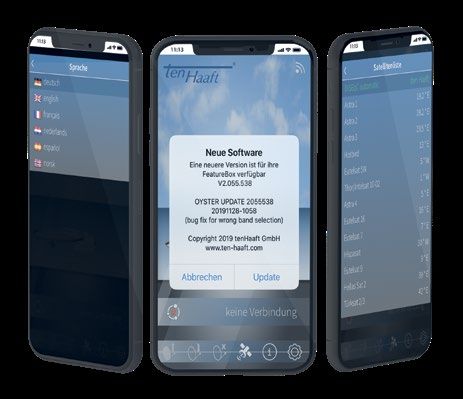
KURZBETRIEBSANLEITUNG VISION CONTROL CENTER                                                            KURZBETRIEBSANLEITUNG VISION CONTROL CENTER
2. MONTAGE                                                                                             2. MONTAGE
2.2 Anschlussplan                                                                                      ANSCHLUSSKENNZEICHNUNG AN DEM VISION CONTROL CENTER

                                                                                                                                                                              {
                                                                                                        Nummer   Erklärung
                                                            Fahrtrichtung
                                                                                                           1     Außeneinheit
        3                                                                                                  2     Montageplatte
                                                                                1                                                                                                     Vorhandene
                                                                                                           3     Winkelverschraubung / Dachdurchführung                             Antennenanlage
                                                                                                           4     Zuleitung von Außeneinheit (schwarzer Schlauch)
                                                                            2                              5     Vision Control Center
             4                                                                                             6     Bedienteil (falls im Lieferumfang enthalten)
                                                                                    6                      7     Koaxialkabel zum Empfangsgerät
                                                                                                           8     Receiver / TV mit integriertem Receiver
                                                                                                                 Schließen Sie hier den Antennenstecker (F-Stecker) des mitgelieferten Steuerkabels zur Auße-
                                                                                                           9     neinheit an. (Steuerkabel und Koaxkabel zur Außeneinheit befinden sich gemeinsam in einer
                                                                                                                 schwarzen Ummantelung)
                                                                                                          10     Sicherung 10A (FKS Mini, rot)
                                                                                                                 Schließen Sie hier das mitgelieferte Stromversorgungskabel an.
                                                                                8
                                                                                                                 ACHTUNG!
                                                                 7
                                                                                                                 Stellen Sie vorher sicher, dass das Stromversorgungskabel am anderen Ende korrekt an das
                                                                                                                 Stromnetz des Fahrzeuges angeschlossen ist, bei Falschpolung kann das Vision Control Center
                                                                                                          11     zerstört werden!

                                                                                                                 Bordnetzklemme 15: Zündung / ggf. D+ (siehe 2.1) (schwarz)
                       5
                                                   9                                                             Bordnetzklemme 30: Bordspannung 12V / 24 V DC (rot)
                               10                                                                                Bordnetzklemme 31: Fahrzeugmasse / Chassis (Braun)

                                                                                12           13           12     Anschlusskabel (braun - Minuspol)
                                                                                                  15
                                                                                                          13     Anschlusskabel (rot - Pluspol)
                                    Battery   11
                                                                                                          14     Aufbau-Batterie
                           Antenna Control
                                                                                        14        16
                                                                                                          15     Anschlusskabel (schwarz - Sicherheitsschaltung)
                                                                                                          16     Zündung Klemme 15 von Fahrzeug
                                                                                                          17     Optionales TWIN Kabel
                                                                                                          18     2. Fernsehgerät nur bei TWIN-LNB
     17                                                18
    nur bei TWIN
    Anlage (optinal)

4                                                                                                                                                                                                               5
KURZBETRIEBSANLEITUNG VISION CONTROL CENTER KURZBETRIEBSANLEITUNG VISION CONTROL CENTER
3. BEDIENELEMENTE
3.1 Bedienteil (falls im Lieferumfang enthalten)
Bedientasten
Achtung: Falls Bedienteil nicht im Lieferumfang enthalten: 1. USB USB-Schnittstelle (für Updates via USB-Stick)
nur das Bedienteil V5 ist kompatibel zum Vision Control Center! 2. Powertaste Hier kann das komplette Antennensystem ein- und ausgeschaltet werden.
Wird diese Taste während der Antennenbewegung gedrückt, erfolgt ein
sofortiger Stop (Not-Stop).
Ein / Aus Bei offener, gestoppter Antenne erfolgt durch Drücken dieser Taste das
Einfahren (Parken) und Abschalten (Standby) der Anlage.
3. „Stern“ Taste Reserviert
Menübedienung „zurück“
4. „i“ Taste Diese Taste hat je nach Farbe der LED‘s verschiedene Funktionen.
Menübedienung „vorwärts“
Menübedienung „OK“
Antenna
Control1 SAT
Ant. TV
Dieses Bedienteil können Sie an einem beliebigen Ort im Fahrzeuginneren anbringen, berücksichtigen Sie aber 10 A CI
Bus
bitte, dass es nicht wasserdicht ist. Eventuell müssen Sie noch die Schutzfolie von der Anzeige abziehen. 31 30 15
Battery
Im Anzeigefeld des Bedienteiles erhalten Sie diverse Informationen über den aktuellen Betriebszustand Ihrer
Anlage. Um diese Informationen ablesen zu können, empfiehlt es sich, das Bedienteil an einem zugänglichen Anschlüsse
Ort zu platzieren.
1. Antennensteuerung 14-poliges Steuerkabel Außeneinheit
Da die Anzeige beleuchtet ist, kann sie auch bei Montage an einem sehr dunklen Ort problemlos abgelesen 2. Spannungsversorgung Zündung/ Klemme 15/ D+ sowie 12 V/ 24V Bordspannungsversorgung
werden.
3. Sicherung 10 A (FSK Mini, rot)
Bitte stecken Sie aus Gründen der Betriebssicherheit das Bedienteil nur aus, während Ihre Außeneinheit im 4. Ant SAT In von der Außeneinheit (Antenne)
Ruhezustand ist. Dies erkennen Sie daran, dass keinerlei Text in der Anzeige eingeblendet ist. 5. TV SAT Out zum Receiver/ TV
Ohne ein Bedienteil wird die Anlage vom angeschlossenen Oyster® TV gesteuert. Darüber hinaus ist die Bedie- 6. Mode Drehschalter SAT-Auswahl (Grundstellung 0 = Automatikmodus)
nung über die kostenlos verfügbare ten Haaft® App über Smartphone / Tablet möglich. 7. CI-Bus Optionaler Steuerungseingang
8. CTRL Anschluss Bedienteil (falls im Lieferumfang enthalten)
3.2 Vision Control Center (Vorderseite) (Rückseite) 9. WLAN WLAN-Antenne
Das Vision Control Center steuert entweder über ein verkabeltes Bedienteil, über die App oder über den Oyster®
3.3 Warnton Vision Control Center
TV die Funktion der Außeneinheit.
Das Vision Control Center erzeugt einen Warnton, wenn der Fahrzeugmotor gestartet wird und die Antenne sich
nicht in ihrer endgültigen Parkposition befindet.
Wird der Fahrzeugmotor bei offener Antennenanlage gestartet, beginnt die Antenne umgehend mit dem Ein
fahren. Dies kann bis zu 40 Sekunden dauern. Ein kurzer Signalton ertönt und weist darauf hin, dass die Antenne
noch vollständig einfahren muss, bevor das Fahrzeug bewegt werden darf.
Wenn das Einfahren der Antenne aufgrund einer Störung nicht vollständig möglich ist ertönt ein perma-
nenter Warnton. Dieser Warnton verstummt erst, wenn die Anlage vollständig eingefahren ist oder die
Das Vision Control Center
Zündung des Fahrzeugs (Klemme 15) abgeschaltet wird.
6 7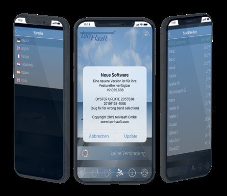
KURZBETRIEBSANLEITUNG VISION CONTROL CENTER KURZBETRIEBSANLEITUNG VISION CONTROL CENTER
4. MENÜFÜHRUNG BEDIENTEIL
Menu-System Vision Control Center für Caro
Einstellungen
Satelliteneinstellungen
→ Manuelle Suche
Azimuth Links/Rechts
Links/Rechts ändert den Azimuth (inändert den Azimuth (in 1° Steps)
1° Steps)
Elevation Links/Rechts ändert dieLinks/Rechts
Elevation (inändert die Elevation (in 1° Steps)
1° Steps)
Skew Links/Rechts
Links/Rechts ändert den Skew (in 1°ändert
Steps)den Skew (in 1° Steps)
Speichern Speichert die Werte und aktiviertdieden
Speichert Modus
Werte und aktiviert den Modus
→ Manueller Transponder
→ Frequenz Frequenz
Frequenz in MHz (10500 in MHz (10500 - 12900)
- 12900)
→ Polarisation High/Low High/Low
→ Symbolrate Symbolrate (12000 - 45000)
Symbolrate (12000 - 45000)
→ FEC-Rate Auswahl aus Liste mit Auswahl
möglichen
ausFEC-Raten
Liste mit möglichen FEC-Raten
→ Modulationsart „QPSK“,
"QPSK", "QPSK-S2" oder "8PSK"„QPSK-S2“ oder „8PSK“
→ ONID Network ID Network ID
→ Aktiv "Ja" oder "Nein". Wenn„Ja“
einoder „Nein“.Transponder
manueller Wenn ein manueller
aktiv ist, Transponder aktiv"Manual
wird im Display ist, wirdMode"
im Display „Manual Mode“ angezeigt.
angezeigt.
→ Receiver Control
→ Modus „Aus“,
"Aus", "Automatik" oder „Automatik“
"OpenSleep" oder „OpenSleep“
(LNB-Off (LNB-Off
schaltet in den schaltet
SleepMode mit in den SleepMode
offener Antenne). mit offener Antenne).
→ Switch-On Delay Verzögerungszeit
Verzögerungszeit bis zum bis der
erneuten Prüfen zumLNB-Spannung
erneuten Prüfen
fürder
dasLNB-Spannung für das Einschalten (3-90s)
Einschalten (3-90s)
→ Switch-Off Delay Verzögerungszeit
Verzögerungszeit bis zum bis der
erneuten Prüfen zumLNB-Spannung
erneuten Prüfen
fürder
dasLNB-Spannung für das Ausschalten (1-30s)
Ausschalten (1-30s)
→ DiSEqC-Zuordnung
→ Modus
→ Modus Auswahl unter vier Presets:
Auswahl"tenunter
Haaft"
vier(®Presets:
Default),„ten
"manuell", "NL Canal „manuell“,
Haaft“ (•Default), Digitaal" und
„NL"NL Joyne"
Canal Digitaal“ und „NL Joyne“
→ Sat 1 (manuell)
→ DiSEqC-Position "Aus" oder 0-255 (Positionsnummer des (Positionsnummer
„Aus“ oder 0-255 Satelliten) des Satelliten)
→ Satellit Name
Name des Satelliten, der für des
dieseSatelliten, der für diese
Position angezeigt Position
werden soll angezeigt werden soll
→ Sat 2 (manuell)
→ … … wie bei "Sat 1" … wie bei „Sat 1“
8 9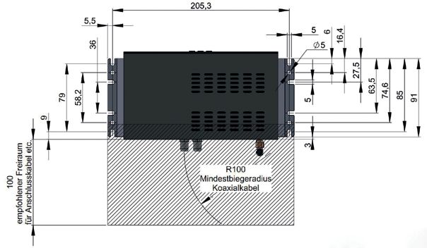
KURZBETRIEBSANLEITUNG VISION CONTROL CENTER                                                                KURZBETRIEBSANLEITUNG VISION CONTROL CENTER

Menu-System Vision Control Center für Caro

                                             → Sat 3 (manuell)
                                                                     → …   … wie bei "Sat 1"               … wie bei „Sat 1“

                                             → Sat 4 (manuell)
                                                                     → …   … wie bei "Sat 1"               … wie bei „Sat 1“

                                             → DiSEqC-Status                                                Anzeige
                                                                           Anzeige der DiSEqC-Version, der Sat-ID,   der der
                                                                                                                   sowie DiSEqC-Version, der Sat-ID, sowie der Bandinformation
                                                                                                                             Bandinformation

                      → Aktueller Standort

                                             → Liste der Standorte

Allgemeine Einstellungen
                      → Sprache                                                                             Links/Rechts
                                                                           Links/Rechts ändert die Sprache sofort         ändert die Sprache sofort (Sprachliste)
                                                                                                                  (Sprachliste)

                      → Bedienteil
                                             → Helligkeit                  Helligkeit von 20-100%          Helligkeit von 20-100%
                                             → Farbe                       Farbwert von 0-100              Farbwert von 0-100
                                             → Ausblendzeit                Ausblendzeit von 2-60s          Ausblendzeit von 2-60s

                      → Wifi
                                             → Aktiv                       "Ja" oder "Nein"                „Ja“ oder „Nein“
                                             → Sendestärke                 3 Stufen (Low/Mid/High)         3 Stufen (Low/Mid/High)
                                             → Kanal                       Kanalnummer                     Kanalnummer
                                             → SSID versteckt              Wlan unsichtbar machen          Wlan unsichtbar machen

Info (Bedienteil)
                      → Antennentyp                                                                       Anzeige der entsprechenden Daten
                                                                           Anzeige der entsprechenden Daten
                      → CI-Bus                                                                               „Ja“, „Nein“,
                                                                           "Ja", "Nein", "Aktiv" oder "Ja (Debug)"         „Aktiv“
                                                                                                                   --> "Aktiv" wirdoder „Ja (Debug)“
                                                                                                                                    angezeigt,       -->Verbindung
                                                                                                                                               wenn eine „Aktiv“ wird
                                                                                                                                                                   zumangezeigt, wenn einewurde
                                                                                                                                                                        Master hergestellt Verbindung zum Master herge-
                                                                                                           stellt wurde
                      → UF Version
                      → DiSEqC-Status                                                                       Anzeige
                                                                           Anzeige der DiSEqC-Version, der Sat-ID,   der der
                                                                                                                   sowie DiSEqC-Version, der Sat-ID, sowie der Bandinformation
                                                                                                                             Bandinformation

10                                                                                                                                                                                                                    11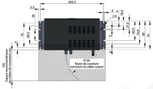
KURZBETRIEBSANLEITUNG VISION CONTROL CENTER KURZBETRIEBSANLEITUNG VISION CONTROL CENTER
Menu-System Vision Control Center für Caro
Bei "Info" "OK" lang gedrückt ("Update" bei der App lang gedrückt)
→ System
→ Test Limits
→ Start Test… Startet den Testlauf mit denden
Startet Maximalpositionen
Testlauf mit den Maximalpositionen
Minimale Elevation Einschränkung der Minimalelevation
Einschränkung derum spezielle Einbausituationen
Minimalelevation zu erlauben
um spezielle Einbausituationen zu erlauben
Maximale Elevation Einschränkung der Maximalelevation
Einschränkung derum spezielle Einbausituationen
Maximalelevation zu erlauben
um spezielle Einbausituationen zu erlauben
→ Demo Mode "Off, ""Demo1" bis "Demo9"
„Off, „“Demo1“ bis „Demo9“
Elevationsposition des Demo-Mode Satelliten (10-50°)
Azimutposition des Demo-Mode Satelliten (10-350°)
→ Armjustage
→ Start… Mit der OK- Taste wird
Mitdie
derausgefahrene
OK- Taste wirdAntenne bis zum Endschalter
die ausgefahrene Antenne bis eingefahren
zum Endschalter eingefahren
→ LNB Erkennung "on" (Default) oder "off"
„on“ --> Möglichkeit,
(Default) die-->
oder „off“ LNB-Erkennung fürLNB-Erkennung
Möglichkeit, die schwierige Fälle
fürauszuschalten
schwierige Fälle auszuschalten
→ Signalanpassung "Optimal", "Stufe 0",„Optimal“, „Stufe 2"
Stufe 1", "Stufe 0“, oder
Stufe"Stufe
1“, „Stufe
3" 2“ oder „Stufe 3“
→ Modell-Auswahl Möglichkeit zur Auswahl der angeschlossenen
Möglichkeit zur Auswahl derAußeneinheit
angeschlossenen Außeneinheit
→ Oyster 4 (4pol)
→ Cytrac/Caro+ (4pol)
→ Caro (14pol)
→ Oyster (14pol)
12 13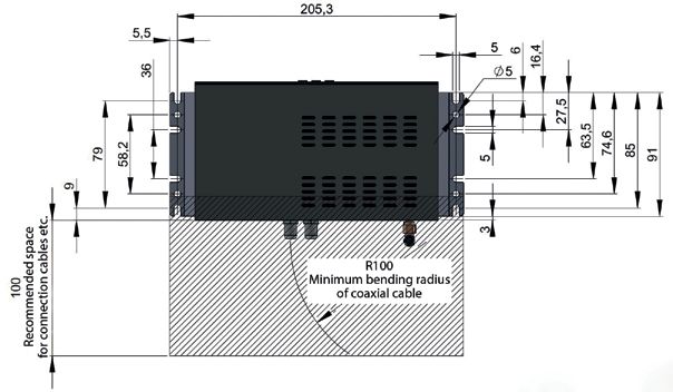
KURZBETRIEBSANLEITUNG VISION CONTROL CENTER                                                                               KURZBETRIEBSANLEITUNG VISION CONTROL CENTER
5. ANHANG
5.1 Hinweis zum Umweltschutz                                                                                              5.2 Konformitätserklärung CE

Altfahrzeugverordnung - ELV
Das Antennen-System ist als Zubehör zur Verwendung auf Kraftfahrzeugen zertifiziert und vorgesehen. Die Entsorgung kann
demgemäß im Rahmen der Altfahrzeug-Verordnung (Europäische Altfahrzeugrichtlinie ELV, 2000/53/EG; für Deutschland:
AltfahrzeugV) zusammen mit dem Kraftfahrzeug erfolgen. Das Antennen-System enthält keine der gemäß Richtlinie als
umweltschädlich eingestuften Stoffe.

Wir wünschen Ihnen viel Freude mit Ihrer SAT-Anlage

Ihr ten Haaft Team

ten Haaft GmbH

Neureutstraße 9
75210 Keltern
Deutschland

Tel.:           +49 (0) 7231 / 58588-0
Fax:            +49 (0) 7231 / 58588-119
E-Mail:         service@ten-haaft.com
Homepage:       www.ten-haaft.com

14                                                                                                                                                                  15
KURZBETRIEBSANLEITUNG VISION CONTROL CENTER                                                                  KURZBETRIEBSANLEITUNG VISION CONTROL CENTER
6. BEDIENUNG DER ANLAGE

6.1 ten Haaft® App - Download, Installation und erstes Software - Update                                     Besuchen Sie den Apple App Store oder den Google Play Store und suchen sie nach den Begriff „ten Haaft“.
                                                                                                             Laden sie die App kostenlos herunter und öffnen sie dann.
Ganz besonders nutzerfreundlich lassen sich alle mobilen Satellitenanlagen von ten Haaft mit der dazuge-
hörigen App bedienen. Nicht nur Grundfunktionen der Anlage lassen sich bedienen, wie etwa das Aus- und
Einfahren der Antenne, sondern auch sehr detaillierte System-Einstellungen oder Informationen über den
aktuellen Betriebszustand der Anlage lassen sich bequem über den Bildschirm Ihres Smartphones bedienen
und abrufen.

Ein wesentlicher Vorteil der ten Haaft® App ist die intuitiv zu bedienende Software-Updatefunktion für die
Satellitenanlage. Regelmäßige Software-Updates sind essenziell für den reibungslosen Betrieb der Satel-
litenanlage, da hierbei funktionell wichtige Datenbanken auf den neuesten Stand gebracht werden. Beim
Start der ten Haaft App werden Sie automatisch auf verfügbare Updates hingewiesen. Der Download und
die Installation der Software erfolgen dann weitgehend automatisiert und benötigen nur wenige Finger-
tipps des Benutzers auf dem Bildschirm.

                                                                                                                                   iPhone                                                     Android

                                                                                                             Die App fragt bei der Installation den Zugriff auf die Standortfreigabe ab. Dieser muss zumindest während
                                                                                                             der Verwendung der App gestattet sein. Die App kann die Standort-Daten auch dazu nutzen, um Ihrer Sa-
                                                                                                             tellitenanlage automatisch den momentanen Standort mitzuteilen, damit der Satellit schneller gefunden
                                                                                                             werden kann. Ganz ohne Standortfreigabe ist die Verwendung bei manchen Smartphone-Betriebssystemen
                                                                                                             gegebenenfalls gar nicht möglich.

                                                                                                                                  iPhone                                                      Android

16                                                                                                                                                                                                                 17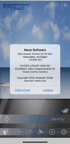
KURZBETRIEBSANLEITUNG VISION CONTROL CENTER                                                                      KURZBETRIEBSANLEITUNG VISION CONTROL CENTER

Die App fragt im weiteren Installationsverlauf einige Dinge ab, zum Beispiel ob Sie den QR-Code der
FeatureBox parat haben. Bitte beachten Sie, dass Ihre FeatureBox mit drei gleichen Aufklebern versandt wird.
Auf diesem Aufklebe befindet sich der WLAN-Name/SSID sowie das WLAN-Passwort für Ihre FeatureBox. Jede
FeatureBox hat einen eigenen Namen und ein eigenes Passwort!

Einer der Aufkleber befindet sich bereits werksseitig auf der FeatureBox, ein weiterer Aufkleber befindet sich
ebenfalls bereits werksseitig auf dieser Beschreibung. Den dritten Aufkleber können Sie nach Bedarf an einem
Ort Ihrer Wahl anbringen.

Priorität für die Bedienung Ihrer Anlage hat immer der Aufkleber auf Ihrer FeatureBox!

Als Nächstes braucht die App Zugang zur Kamera
Ihres Gerätes, da ansonsten der QR-Code nicht ge-
scannt werden kann.

                                                                            iPhone

                                               Richten Sie die Kamera dann auf den QR-Code Ihres Gerä-
                                               tes. Sobald der Code erkannt wurde, wird der nächste Schritt
                                                                                                                 Der rote bzw. grüne Punkt in der linken, unteren Ecke symbolisiert den Verbindungsstatus zwischen der ten
                                               eingeleitet:
                                                                                                                 Haaft App und der FeatureBox: Ein rotes „X“ zeigt eine fehlende Verbindung an, ein grüner Punkt zeigt eine
                                               Bitte bestätigen Sie die Verbindungsaufnahme mit dem WLAN         aktive Verbindung an. Im Normalfall sollte der Zustand nach einigen Sekunden vom roten „X“ auf den grü-
                                               wie auf dem Bildschirm dargestellt.                               nen Punkt wechseln. Falls dies nicht geschieht, so kann man den Verbindungsaufbau nochmals anstoßen,
                                                                                                                 indem man auf das rote „X“ klickt.

                 Android

18                                                                                                                                                                                                                      19
KURZBETRIEBSANLEITUNG VISION CONTROL CENTER KURZBETRIEBSANLEITUNG VISION CONTROL CENTER
Wichtiger Zwischenschritt: Bei manchen Smartphone-Betriebs- Die Software wird vom Smartphone über dessen LTE-Verbin-
systemen ist es ratsam die App nun noch einmal komplett zu dung heruntergeladen. Die Größe des Downloads liegt bei nur
beenden. Das bedeutet, dass die App nicht nur in den Hinter- etwa 3 - 4 Megabyte. Bitte stellen Sie sicher, dass Ihr Smart-
grund verschoben wird, sondern tatsächlich beendet. phone eine funktionierende Internetverbindung besitzt.
Erst beim nächsten Start der App wird dann automatisch Nach Abschluss des Downloads überprüft die App automa-
überprüft, ob auf dem ten Haaft-Server eine neuere Software tisch, ob sich auf Ihrer Anlage bereits die aktuellste Software
für Ihre Anlage vorhanden ist. Manche Smartphone-Betriebs- befindet. Wenn nicht, dann wird automatisch vorgeschlagen
systeme machen dies auch automatisch. ein Update durchzuführen.
Bitte klicken Sie dann auf „Update“.
Klicken Sie hierfür auf „Start Update“.
20 21KURZBETRIEBSANLEITUNG VISION CONTROL CENTER KURZBETRIEBSANLEITUNG VISION CONTROL CENTER
Während der Installation des Software-Updates sehen Sie einen grünen Balken durchlaufen. Im Normalfall
sollte das Ende der Installation mit dem Bild oben rechts angezeigt werden. Bei manchen Smartpho-
ne-Betriebssystemen bleibt der Balken jedoch manchmal auch etwa bei der Mitte stehen und bewegt sich
danach nicht mehr weiter. In diesem Fall warten Sie bitte etwa drei weitere Minuten und beenden die App
anschließend und starten sie danach wieder neu.
Wenn Sie weitere Fragen haben, stehen wir Ihnen gerne zur Verfügung! Bitte rufen Sie uns an unter +49 (0)
7231 / 58 588 0. Weitere Informationen und Erläuterungen zur ten Haaft App finden Sie auch auf unserem
YouTube Channel unter Firma ten Haaft GmbH oder Scannen Sie den QR Code ab.
Sie können die erfolgreiche Installation des Software Update anschließend leicht selbst kontrollieren:
Tippen Sie unten rechts auf das „i“ Symbol und vergleichen dann die beiden Zahlenreihen, die bei „UF Ver-
sion FB“ und bei „UF Version App“ stehen. Sind beide Zahlen gleich, dann ist die Software in der FeatureBox
bereits erfolgreich aktualisiert worden.
22 23KURZBETRIEBSANLEITUNG VISION CONTROL CENTER KURZBETRIEBSANLEITUNG VISION CONTROL CENTER 7. PLATZBEDARFSSKIZZE FÜR DAS VISION CONTROL CENTER 7. PLATZBEDARFSSKIZZE FÜR DAS VISION CONTROL CENTER 24 25
SHORT USER MANUAL VISION CONTROL CENTER                             SHORT USER MANUAL VISION CONTROL CENTER
Contents                                                            1. GENERAL INFORMATION
1. General information                                              1.1 Safety precautions

1.1 Safety precautions                                         27   Read the operating manual and installation instructions carefully before installing the system. Correct and safe operation of
                                                                    the system can only be ensured if both the installation instructions and the operating instructions are observed.
2. Montage

2.1 Power supply                                               27   2. MONTAGE
2.2 Connections                                                28   2.1 Power supply

3. Control elements                                                 1. Ensure that the system is supplied with sufficient power
                                                                    a) The system must be connected to the 12/24-V onboard electric system.
3.1 Control panel (if included in supply)                      30
3.2 Vision Control Center (front face) (rear face)             31   b)   Be sure to connect the black cable of the 3-line power supply harness to terminal 15 (switched ignition supply) of the
3.3 Warning Tone Vision Control Center                         31         vehicle. Alternatively, you can also connect the black cable to line D+ (generator positive terminal, only live when
                                                                          engine is running) instead of terminal 15, your vehicle’s electric system permitting. In both cases, be sure to make a
4. Menu guidance at control panel
                                                                          function check! In both cases, both you must double-check that the safety circuit functions reliably! Keep in mind that

4.1 Menu guidance at control panel                             32         in some vehicles it is not permissible to connect additional power consumers to the D+ line! Note that in some vehicles,
                                                                          the voltage on the D+ line may be switched off temporarily by the vehicle’s electric system while driving. This would
5. Appendix                                                               prevent the safety circuit from functioning properly! When deciding for this type of connection, make sure that the
                                                                          voltage on the D+ line is present at all times and stable while the engine is running. When in doubt, connect the safety
5.1 Notes on the protection of the environment                 38
                                                                          circuit to a line supplied via terminal 15 (via the ignition lock).
5.2 Declaration of conformity CE                               38

6. Operating the system

6.1 ten Haaft App                                              40

7. Installation space required for the Vision Control Center

7. Installation space required for the Vision Control Center   48

26                                                                                                                                                                                                    27
SHORT USER MANUAL VISION CONTROL CENTER SHORT USER MANUAL VISION CONTROL CENTER
2. MONTAGE 2. MONTAGE
2.2 Connections CONNECTIONS AT THE VISION CONTROL CENTER
{
Number Explanation
Direction of travel
1 Antenna unit
3 2 Mounting plate
1 Present
3 Elbow fitting / roof feed-through antenna system
4 Satellite harness from exterior unit (black hose)
2 5 Vision Control Center
4 6 Control panel (if included in supply)
6 7 Coaxial cable to receiver
8 Receiver / TV mit integriertem Receiver
Connect here the antenna plug (F plug) of the provided control cable to the external unit.
9
(Control cable and coax cable to the external unit are together in a black sheath.)
10 Fuse
Connect the power-supply cable provided here.
Separate
CAUTION!
8 power
supply Ensure that the other end of the power-supply cable is correctly connected to the onboard
7 11 electric system. If polarity is reversed, the Vision Control Center may be destroyed!
Onboard system terminal 15: Ignition / D+ (optional, see 2.1) (black)
Onboard system terminal 30: Onboard system voltage 12/24V DC (red)
Onboard system terminal 31: Vehicle ground / chassis (brown)
5
9 12 Connecting cable (brown – battery negative)
10 13 Connecting cable (red – battery positive)
12 13
15 14 Body battery Coaxial cable to receiver
Battery 11 15 Connecting cable (black – safety circuit)
Antenna Control
14 16 16 Ignition-switched terminal 15 of vehicle
17 Optional TWIN cable
18 2. TV set only with TWIN-LNB
Separate
17 18 power
supply
only with TWIN
(optional)
28 29SHORT USER MANUAL VISION CONTROL CENTER SHORT USER MANUAL VISION CONTROL CENTER
3. CONTROL ELEMENTS
3.1 Control panel (if included in supply)
Control panel
Attention: If the control panel is not included in the scope of delivery: 1. USB USB port (for updates via USB stick)
only the V5 control panel is compatible with the Vision Control Center! 2. Power button This button switches the entire antenna system on and off. If you press
this button while the antenna is in motion, it will stop immediately
(emergency stop).
On / Off When the antenna is open and stopped, pressing this key will cause the
system to retract (park) and shut down (standby).
3. „Star“ button reserved
Menu command "forward"
4. „i“ button This button has various functions that are indicated by the colour of the
LED.
Menu command "back"
Menu command "OK"
Antenna
Control1 SAT
Ant. TV
You may choose any location you like to install the control panel, but please bear in mind that it is not water-
10 A CI
proof. You may still need to remove the protective film from the display. Bus
31 30 15
Battery
The display of the control panel will show the various operating modes of the system. We recommend you to
install the control panel in a location where the display is clearly visible.
Inputs/outputs
The display is illuminated, so it is not a problem if it is installed in a very dark location.
1. Antenna control 14-pin plug contracable external unit
To ensure safe and reliable operation of the system, please make sure the external unit is in rest mode before 2. Powersuply Ignition/ terminal 15/ D+ and 12V/ 24V powersupply
disconnecting the control panel. Check that no text is shown in the display – this is an indication that the system 3. Fuse 10 A (FKS-Mini, red)
is in rest mode.
4. Ant SAT IN from external unit (Antenna)
Without control panel, the system is controlled by the Oyster® TV connected to it. You can also control the 5. TV set SAT OUT to Receiver/ TV
system using your mobile device or tablet with the free ten Haaft® app. 6. Mode Rotary switch for SAT mode (default setting 0 = automatic mode)
7. CI-Bus Optional control input
3.2 Vision Control Center (front face) (rear face)
8. CTRL Control panel (if included in supply)
The Vision Control Center controls either the functions of the external unit via a hard-wired control panel, via 9. WLAN WLAN antenna
the app or via the Oyster® TV.
3.3 Warning Tone Vision Control Center
The Vision Control Center will sound a warning tone if the vehicle engine is started before the antenna is fully
retracted and in its ‘Park’ position.
If the vehicle engine is started whilst the antenna is still open, the antenna will automatically retract. This can
take up to 40 seconds. A short signal tone will indicate that the antenna must retract fully before the vehicle
can be moved.
If the antenna, for whatever reason, cannot be fully retracted, a constant warning tone will be heard. This
warning tone will only stop once the antenna is either fully retracted or the vehicles ignition (Terminal
Das Vision Control Center
15) is turned off.
30 31SHORT USER MANUAL VISION CONTROL CENTER SHORT USER MANUAL VISION CONTROL CENTER
4. MENU GUIDANCE AT CONTROL PANEL
Menu-System Vision Control Center für Caro
Settings
Satellite settings
→ Manual search
Azimuth Left / right changes the
Leftazimuth (in increments
/ right changes of 1°) (in increments of 1°)
the azimuth
Elevation Leftelevation
Left / right changes the / right changes the elevation
(in increments of 1°)(in increments of 1°)
Skew Leftskew
Left / right changes the / right changes
angle the skew angle
(in increments of 1°)(in increments of 1°)
Save Saves the values and Saves
activates
the the mode
values and activates the mode
→ Manual transponder
→ Frequency Frequency in MHz (10500 - 12900)
Frequency in MHz (10500 - 12900)
→ Polarisation High/Low High/Low
→ Symbol rate Symbol rate (12000 - Symbol
45000) rate (12000 - 45000)
→ FEC rate Selection from a list ofSelection
applicable FEC
from rates
a list of applicable FEC rates
→ Modulation rate "QPSK", "QPSK-S2" or„QPSK“,
"8PSK" „QPSK-S2“ or „8PSK“
→ ONID Network ID Network ID
→ Active "Yes" or "No". The display
„Yes“ shows
or „No“."Manual mode"
The display when
shows a manual
„Manual transponder
mode“ is active.
when a manual transponder is active.
→ Receiver Control
→ Modus "Off", "Automatic" or„Off“,
"OpenSleep" (LNBorOff
„Automatic“ switches the
„OpenSleep“ system
(LNB into sleep
Off switches themode with
system the
into antenna
sleep moderemaining unfolded)
with the antenna remaining
unfolded)
→ Switch-On Delay Delay until the next check
Delayofuntil
the the
LNBnext
voltage
checkforofpower-up (3–90 sec.)
the LNB voltage for power-up (3–90 sec.)
→ Switch-Off Delay Delay until the next check
Delayofuntil
the the
LNBnext
voltage
checkforofpower-down (1–30
the LNB voltage forsec.)
power-down (1–30 sec.)
→ DiSEqC allocation
→ Mode
→ Mode Four presets can be selected: "tencan
Four presets Haaft" (default),„ten
be selected: "manual", "NL Canal
Haaft“ (default), Digitaal"„NL
„manual“, andCanal
"NL Joyne"
Digitaal“ and „NL Joyne“
→ Sat 1 (manual)
→ DiSEqC-Position "Off" or 0 – 255 (position
„Off“number of satellite)
or 0 – 255 (position number of satellite)
→ Satellite Name of satellite to be shown
Name for this position
of satellite to be shown for this position
→ Sat 2 (manual)
→ … ... as with "Sat 1" ... as with „Sat 1“
32 33SHORT USER MANUAL VISION CONTROL CENTER SHORT USER MANUAL VISION CONTROL CENTER
Menu-System Vision Control Center für Caro
→ Sat 3 (manual)
→ … ... as with "Sat 1" ... as with „Sat 1“
→ Sat 4 (manual)
→ … ... as with "Sat 1" ... as with „Sat 1“
→ DiSEqC-status Display of the DiSEqC version, theDisplay of the
Sat ID and theDiSEqC version, the Sat ID and the band information
band information
→ Curretn location
→ List of locations Anzeige der DiSEqC-Version, der Sat-ID, sowie der Bandinformation
General settings
→ Language Links/Rechts ändert die Sprache sofort
Left / (Sprachliste)
Right changes the language immediately (language list)
→ Display
→ Brightness Brightness 20% – 100% Brightness 20% – 100%
→ Colour Colour 0% – 100% Colour 0% – 100%
→ Fade-out Fade-out time 2–60 sec. Fade-out time 2–60 sec.
→ Wifi
→ Active "Yes" or "No" „Yes“ or „No“
→ Transmit power 3 Steps (Low/Mid/High) 3 Steps (Low/Mid/High)
→ Channel Channel number Channel number
→ SSID hidden Make WiFi invisible Make WiFi invisible
Info (Display)
→ Antenna type Display of corresponding data Display of corresponding data
→ CI-Bus „Yes“,->„No“,
"Yes", "No", "Active" or "Yes (Debug)" „Active“
"Active" or „Yeswhen
is displayed (Debug)“ -> „Active“
a connection is displayed
to the master haswhen
beenaestablished
connection to the master has been
established
→ UF Version
→ DiSEqC Status Display of the DiSEqC version, theDisplay of the
Sat ID and theDiSEqC version, the Sat ID and the band information
band information
34 35SHORT USER MANUAL VISION CONTROL CENTER SHORT USER MANUAL VISION CONTROL CENTER
Menu-System Vision Control Center für Caro
Press and hold "OK" on "Info" (press and hold "Update" on the app)
→ System
→ Test Limits
→ Start Test… Starts the test run with
Startsthe
themaximum positions
test run with the maximum positions
Minimal Ealevation Restriction of the minimum elevation
Restriction to allowelevation
of the minimum special installation situations
to allow special installation situations
Maximal Elevation Restriction of the maximum
Restrictionelevation to allowelevation
of the maximum special installation situations
to allow special installation situations
→ Demo Mode "Off," "Demo1" to "Demo9"
„Off,“ „Demo1“ to „Demo9“
Elevation position of the demo mode satellite (10-50 °)
Azimuth position of the demo mode satellite (10-350 °)
→ Arm Adjust
→ Starting… With the OK button,With
the the
extended antenna
OK button, is retracted
the extended to the
antenna limit switch
is retracted to the limit switch
→ LNB Detection "on" (default) or "off"
„on“->(default)
possibility to switch
or „off“ off the LNB
-> possibility detection
to switch in LNB
off the difficult casesin difficult cases
detection
→ Signal Adjust "Optimal", "Level 0", Level 1 ","
„Optimal“, Level
„Level 0“,2Level
"or" 1Level 3 " 2 „or“ Level 3 „
„,“ Level
→ Model Selection Possibility to select Possibility to select
the connected the connected
external unit external unit
→ Oyster 4 (4pol)
→ Cytrac/Caro+ (4pol)
→ Caro (14pol)
→ Oyster (14pol)
36 37SHORT USER MANUAL VISION CONTROL CENTER SHORT USER MANUAL VISION CONTROL CENTER 5. APPENDIX 5.1 Notes on the protection of the environment 5.1 Declaration of conformity CE EC End-of-Life Vehicle Directive The antenna system is certified and intended for use as an accessory of a motor vehicle. The system may be disposed of together with the vehicle in accordance with the End-of-Life Vehicle Directive ELV, 2000/53/EC. The antenna system does not contain any materials rated as hazardous to the environment according to the directive. We hope your satellite system brings you lots of joyful entertainment hours Your ten Haaft Team ten Haaft GmbH Neureutstraße 9 75210 Keltern Deutschland Tel.: +49 (0) 7231 / 58588-0 Fax: +49 (0) 7231 / 58588-119 E-Mail: service@ten-haaft.com Homepage: www.ten-haaft.com 38 39
SHORT USER MANUAL VISION CONTROL CENTER                                                                             SHORT USER MANUAL VISION CONTROL CENTER
6. OPERATING THE SYSTEM

6.1 ten Haaft® app - download, installation and first software update                                               Visit the Apple App Store or the Google Play Store and search for “ten Haaft”. Download the app free of charge
                                                                                                                    and open it.
All ten Haaft mobile satellite systems can be operated in a particularly user-friendly way with the corresponding
app. It is not only possible to operate the basic functions of the system, such as extending and retracting the
antenna, but also to make very detailed system settings or call up information about the current operating status
of the system conveniently via the screen of your smartphone.

A major advantage of the ten Haaft® app is the intuitive software update function for the satellite system. Reg-
ular software updates are essential for the smooth operation of the satellite system, as functionally important
databases are brought up to date. You are automatically notified of available updates when starting the ten
Haaft app. The download and installation of the software is then largely automated and only requires a few taps
on the screen by the user.

                                                                                                                                           iPhone                                                          Android

                                                                                                                    During installation, the app requests access to location sharing. This authorisation needs to be granted at least
                                                                                                                    while using the app. The app can also use the location data to automatically inform your satellite system of the
                                                                                                                    current location so that the satellite can be found more quickly. Some smartphone operating systems may not
                                                                                                                    even allow you to use the app without location sharing.

                                                                                                                                           iPhone                                                          Android

40                                                                                                                                                                                                                                41
SHORT USER MANUAL VISION CONTROL CENTER SHORT USER MANUAL VISION CONTROL CENTER
The app will prompt you for a few details during the installation process, such as whether you have
the QR code for the FeatureBox. Please note that your FeatureBox will be shipped with three identical labels.
This label contains the Wi-Fi name/SSID and the Wi-Fi password for your FeatureBox. Each FeatureBox has its
own name and password.
One label is already affixed to the FeatureBox at the factory, a second label is also already affixed to this de-
scription at the factory. You can affix the third label to a place of your choice.
The label on your FeatureBox always has priority for the operation of your system!
Now the app needs access to your device's camera,
otherwise the QR code cannot be scanned.
iPhone
Then aim the camera at the QR code on your device. Once the
code has been recognised, the next step is initiated: The red or green dot in the lower left-hand corner symbolises the connection status between the ten Haaft
app and the FeatureBox: A red “X” indicates a missing connection, a green dot indicates an active connection.
Please confirm that you wish to connect to the Wi-Fi as shown
Normally, the status should change from the red “X” to the green dot after a few seconds. If not, you can initiate
on the screen.
the connection again by clicking on the red “X”.
Android
42 43SHORT USER MANUAL VISION CONTROL CENTER SHORT USER MANUAL VISION CONTROL CENTER
Important intermediate step: For some smartphone operating sys- Software is downloaded from the smartphone via its LTE con-
tems, it is recommended to close the app completely. This means nection. The size of the download is only approx. 3-4 megabytes.
that the app is not just moved to the background, but actually Please make sure that your smartphone has a working internet
closed. connection.
The next time you start the app, it will automatically check Once the download is complete, the app automatically checks
whether more recent software for your system is available on whether the latest software is already installed on your system. If
the ten Haaft server. Some smartphone operating systems also not, it will automatically suggest an update.
do this automatically.
Then please click on “Update”.
For this purpose, click on “Start Update”.
44 45SHORT USER MANUAL VISION CONTROL CENTER SHORT USER MANUAL VISION CONTROL CENTER
During the installation of the software update, you will see a green bar showing the progress. Normally, the
image at the top right should show when the installation is complete. With some smartphone operating systems,
however, the bar sometimes stops in the middle and then does not move any further. In this case, please wait
another three minutes approximately and then close the app and restart it.
If you have any further questions, please do not hesitate to contact us. Please call us at +49 (0)
7231 / 58 588 0. You can also find more information and explanations about the ten Haaft app on our YouTube
Channel at ten Haaft GmbH, or scan the QR code.
You can then easily check the successful installation of the software update yourself:
Tap on the “i” icon at the bottom right and then compare the two series of numbers that appear at “UF Version
FB” and “UF Version APP”. If both numbers are the same, then the software in the FeatureBox has already been
successfully updated.
46 47SHORT USER MANUAL VISION CONTROL CENTER SHORT USER MANUAL VISION CONTROL CENTER 7. INSTALLATION SPACE REQUIRED FOR THE VISION CONTROL CENTER 7. INSTALLATION SPACE REQUIRED FOR THE VISION CONTROL CENTER 48 49
MODE D’EMPLOI ABRÉGÉ VISION CONTROL CENTER                       MODE D’EMPLOI ABRÉGÉ VISION CONTROL CENTER
Table des matières                                               1. GÉNÉRALITÉS
1. Généralités                                                   1.1 Consignes de sécurité

1.1 Consignes de sécurité                                   51   Lisez attentivement les présentes instructions d’utilisation et de montage avant de commencer le montage et l’utilisation. La
                                                                 fiabilité et les performances du système ne peuvent être garanties que si toutes les instructions de montage et d’utilisation ont
2. Montage
                                                                 été observées.

2.1 Alimentation électrique                                 51
2.2 Schéma de câblage                                       52   2. MONTAGE
                                                                 2.1 Alimentation électrique
3. Éléments de commande
                                                                 1. Veillez à ce que l’alimentation électrique du système soit suffisante
3.1 Boîtier de commande (si fourni)                         54
                                                                 a) Le système doit être relié à une tension de bord 12 V / 24 V.
3.2 Vision Control Center (face avant) (face arrière)       55
3.3 Signal d‘avertissement sonore Vision Control Center     39   b)   Il est impératif de connecter le fil noir du câble d’alimentation tripolaire à la borne 15 (+ après contact) du véhicule. Une
                                                                       autre possibilité, si le circuit électrique de votre véhicule le permet, consiste à utiliser le fil D+ (+ de l’alternateur, la tension
4. Guidage par menu sur le boîtier de commande
                                                                       n’est établie que lorsque le moteur est en marche). Dans ces cas, s’assurer que le circuit de sécurité fonctionne

4.1 Guidage par menu sur le boîtier de commande             56         correctement ! À noter que sur un certain nombre de véhicules, le fil D+ ne doit pas être utilisé par des dispositifs externes
                                                                       ! De plus, veuillez noter que sur un certain nombre de véhicules, la tension à la borne D+ peut être temporairement coupée
5. Annexe                                                              par le réseau de bord pendant la conduite. Ceci empêchera le bon fonctionnement du circuit de sécurité ! Par conséquent,
                                                                       assurez-vous que la tension à la borne D+ de votre véhicule est toujours établie lorsque le moteur est en marche. En cas de
5.1 Consignes concernant la protection de l’environnement   62
                                                                       doute, utilisez le fil K15 (+ après contact) pour la connexion au circuit de sécurité.
5.2 Déclaration de conformité CE                            63

6. Fonctionnement du système

6.1 ten Haaft App                                           64

7. Espace nécessaire pour la Vision Control Center

7. Espace nécessaire pour la Vision Control Center          72

50                                                                                                                                                                                                       51
MODE D’EMPLOI ABRÉGÉ VISION CONTROL CENTER MODE D’EMPLOI ABRÉGÉ VISION CONTROL CENTER
2. MONTAGE 2. MONTAGE
2.2 Schéma de câblage CONNEXIONS SUR LA VISION CONTROL CENTER
{
Numéro Explication
Sens de déplacement 1 Unité extérieure
3 2 Plaque de fixation
Actuelle Système
1 3 Raccordement coudé / traversée de toit d‘antenne
4 Ligne d‘alimentation SAT de l‘unité extérieure (tuyau noir)
2 5 Vision Control Center
4 6 Boîtier de commande (si fourni)
7 Câble coaxial allant à l’appareil de réception
6
8 Récepteur / téléviseur avec récepteur intégré
Branchez ici le connecteur d’antenne (connecteur F) du câble de commande fourni allant à
9 l‘unité extérieure. (Le câble de commande et le câble coaxial allant à l’unité extérieure sont
réunis dans une gaine noire).
10 Fusible
Alimentation Branchez ici le câble d’alimentation fourni.
8 en tension
séparée ATTENTION!
7
Assurez-vous au préalable que l’autre extrémité du câble d’alimentation est correctement
11 raccordée au réseau de bord du véhicule. Une erreur de polarité peut détruire la!
Borne 15 du réseau de bord : Contact / D+ le cas échéant (voir 2.1) (noir)
5 Borne 30 du réseau de bord : Tension de bord 12 V / 24 V CC (rouge)
9 Borne 31 du réseau de bord : Masse du véhicule / châssis (brun)
10 12 Câble de raccordement (marron - borne négative)
12 13
15 13 Câble de raccordement (rouge - borne positive)
Battery 11 14 Batterie de cellule habitable
Antenna Control
14 16 15 Câble de raccordement (noir - circuit de sécurité)
16 Borne 15 (contact) du véhicule
17 Câble TWIN en option
18 2. Téléviseur (TWIN-LNB uniquement)
Alimentation
17 18 en tension
séparée
seulement avec TWIN
(optionnel)
52 53MODE D’EMPLOI ABRÉGÉ VISION CONTROL CENTER MODE D’EMPLOI ABRÉGÉ VISION CONTROL CENTER
3. ÉLÉMENTS DE COMMANDE
3.1 Boîtier de commande (si fourni)
boutons de commande
Attention: Si le boîtier de commande n‘est pas inclus dans la livraison: 1. USB Interface USB (pour les mises à jour via une clé USB)
seul le boîtier de commande V5 est compatible avec le Vision Control Center! 2. Touche Marche/Arrêt Cette touche permet de mettre sous et hors tension le système d’antenne
complet. L’activation de cette touche pendant un mouvement de l’an-
Marche/arrêt tenneentraîne l’arrêt immédiat de celle-ci (arrêt d’urgence).
Lorsque l‘antenne est ouverte et arrêtée, appuyez sur cette touche pour
rétracter (se garer) et arrêter (mode veille) le système.
Commande « vers l’arrière » 3. « Star » Touche réservé
4. Touche « i » En fonction de la couleur des LED, cette touche a différentes fonctions.
Commande « vers l’avant »
Commande « OK »
Antenna
Control1 SAT
Ant. TV
Ce boîtier peut être placé à l’endroit de votre choix à l’intérieur du véhicule, en tenant toutefois compte du fait CI
10 A
Bus
qu’il n’est pas étanche. Vous devrez peut-être aussi retirer la feuille de protection de l’affichage.
31 30 15
Battery
Dans la partie affichage du boîtier de commande, vous obtiendrez diverses informations sur l’état de foncti-
onnement instantané du système. Pour pouvoir lire ces informations, il est recommandé de placer le boîtier de
Ports
commande dans un endroit facilement accessible.
1. Commande d‘antenne Unité extérieure de câble de commande à 14 broches
Vous pouvez choisir un endroit très sombre car l’affichage est éclairé.
2. Source de courant Allumage / borne 15 / D + et alimentation de la carte 12V / 24V
Pour des raisons de sécurité de fonctionnement, veuillez ne débrancher le boîtier de commande que lorsque votre 3. Fusible 10 A (FKS-Mini, rouge)
unité extérieure est en mode veille. C’est le cas lorsqu’aucun texte n‘est affiché à l‘écran. 4. Ant Entrée de l’antenne satellite depuis l’unité extérieure
En l’absence de boîtier de commande, le système se commande au moyen du Oyster® TV connecté. Il peut aussi 5. TV Sortie du récepteur satellite vers le téléviseur
être commandé au moyen de l’application gratuite ten Haaft® sur smartphone/tablette. 6. Mode Commutateur de sélection de satellite (position de base 0 = mode automatique)
7. Bus CI Entrée de commande en option
3.2 Vision Control Center (face avant) (face arrière) 8. CTRL Connexion du boîtier de commande (si fourni)
La Vision Control Center commande l’unité extérieure au moyen d’un boîtier de commande câblé, de l’applica- 9. WLAN Antenne WLAN
tion ou du Oyster® TV.
3.3 Signal d‘avertissement sonore Vision Control Center
La Vision Control Center émet un signal d‘avertissement sonore si le moteur du véhicule tourne et que l‘anten-
ne ne se trouve pas complètement en position fermée.
Si le moteur de véhicule est lancé avec l‘antenne ouverte, l‘antenne va se mettre en position fermée. Cela peut
durer jusqu‘à 40 secondes. Avant que le véhicule ne puisse être déplacé, un court signal sonore retentit pour
vous mettre en garde que l‘antenne n‘est pas encore complètement repliée.
Un signal sonore retentit en permanence si l‘antenne n‘est pas complètement repliée, le problème peut
être dû par exemple à un défaut. Le signal sonore ne peut être mis hors service que si l‘antenne est com-
Das Vision Control Center
plètement repliée ou si la borne 15 du contact est débranchée.
54 55MODE D’EMPLOI ABRÉGÉ VISION CONTROL CENTER MODE D’EMPLOI ABRÉGÉ VISION CONTROL CENTER
4. GUIDAGE PAR MENU SUR LE BOÎTIER DE COMMANDE
Menu-System Vision Control Center für Caro
Réglages
Réglage des satellites
→ Recherche manuelle
Azimut Gauche/Droite modifieGauche/Droite
l’azimut (par palier
modifiedel’azimut
1°) (par palier de 1°)
Elévation Gauche/Droite modifieGauche/Droite
l’élévation (par palierl’élévation
modifie de 1°) (par palier de 1°)
Skew Gauche/Droite modifieGauche/Droite
l’obliquité (parmodifie
palier l’obliquité
de 1°) (par palier de 1°)
Mémoriser Enregistre les valeurs etEnregistrer
le mode les valeurs et le mode
→ Transpondeur manuel
→ Fréquence Fréquence
Fréquence en MHz (10500 - 12900)en MHz (10500 - 12900)
→ Polarisation Haut/bas Haut/bas
→ Débit symbole Débit symbole (12000 - Débit
45000)symbole (12000 - 45000)
→ Taux de FEC Sélection depuis une liste des tauxdepuis
Sélection de FECune
possibles
liste des taux de FEC possibles
→ Taux de modulation "QPSK", "QPSK-S2" ou "8PSK"
„QPSK“, „QPSK-S2“ ou „8PSK“
→ ONID Id. réseau Id. réseau
→ Actif « Oui » ou « Non ». Lorsqu’un
« Oui » transpondeur manuel transpondeur
ou « Non ». Lorsqu’un est actif, « Mode manuel
manuel » s’affiche
est actif, « Modesurmanuel
l’écran» s’affiche sur l’écran
Contrôle du
→ démodulateur
→ Mode « Arrêt », « Automatique »«ou
Arrêt », « Automatique
« Ouvert/mode » ou « Ouvert/mode
veille » (l’extinction veille
de la tête de » (l’extinction
réception commute de la têteveille
en mode de réception commute
avec l’antenne en mode
ouverte)
Temporisation veille avec l’antenne ouverte)
→ d’allumage Temporisation jusqu’auTemporisation jusqu’au
nouveau contrôle de lanouveau contrôle
tension de la têtede
delaréception
tension de la tête l’allumage
pendant de réception pendant
(3-90 s) l’allumage (3-90 s)
Temporisation
→ d’extinction Temporisation jusqu’auTemporisation jusqu’au
nouveau contrôle de lanouveau contrôle
tension de la têtede
delaréception
tension de la tête l’extinction
pendant de réception(1-30
pendant
s) l’extinction (1-30 s)
→ Affectation DiSEqC
→ Mode
→ Mode Sélection parmi quatre présélections : «quatre
Sélection parmi ten Haaft » (par défaut),
présélections : « ten«Haaft
manuel », «défaut),
» (par NL Canal Digitaal», »« et
« manuel NL«Canal
NL Joyne » » et « NL Joyne »
Digitaal
→ Sat 1 (manuel)
→ DiSEqC-Position « Arrêt » ou 0-255 (numéro de »position
« Arrêt ou 0-255du(numéro
satellite)de position du satellite)
→ Satellite Nom du satellite devantNom
être du
affiché pourdevant
satellite cette position
être affiché pour cette position
→ Sat 2 (manuel)
→ … ... idem « Sat 1 » ... idem « Sat 1 »
56 57MODE D’EMPLOI ABRÉGÉ VISION CONTROL CENTER MODE D’EMPLOI ABRÉGÉ VISION CONTROL CENTER
Menu-System Vision Control Center für Caro
→ Sat 3 (manuel)
→ … ... idem « Sat 1 » ... idem « Sat 1 »
→ Sat 4 (manuel)
→ … ... idem « Sat 1 » ... idem « Sat 1 »
→ État DiSEqC Affichage de la version DiSEqC, duAffichage
Sat-ID et de
deslainformations
version DiSEqC,
sur ladu Sat-ID et des informations sur la bande
bande
→ Emplacement actuel
Liste des
→ emplacements
Réglages généraux
→ Langue Gauche
Links/Rechts ändert die Sprache sofort / Droite change la langue immédiatement (liste des langues)
(Sprachliste)
→ Afficheur
→ Luminosité Luminosité de 20 à 100 % Luminosité de 20 à 100 %
→ Couleur Valeur chromatique de 0 à 100 % Valeur chromatique de 0 à 100 %
→ Fondu sortant Temps du fondu sortant de 2 à 60 Temps
s du fondu sortant de 2 à 60 s
→ Wifi
→ Actif « Oui » ou « Non » « Oui » ou « Non »
Puissance de
→ transmission 3 niveaux (bas / moyen / haut) 3 niveaux (bas / moyen / haut)
→ Canal Numéro de canal Numéro de canal
→ SSID caché Rendre le WiFi invisible Rendre le WiFi invisible
Information
→ Type d’antenne Affichage des données correspondantes
Affichage des données correspondantes
→ CI-Bus «Oui», «Non»,
«Oui», «Non», «Actif» ou «Oui (Debug)» «Actif»
-> «Actif» ou «Oui
s'affiche (Debug)»connexion
lorsqu'une -> «Actif»avec
s‘affiche lorsqu‘une
le maître connexion avec le maître a été établie
a été établie
→ Version UF
→ Status DiSEqC Affichage de la version DiSEqC, duAffichage
Sat-ID et de
deslainformations sur ladu
version DiSEqC, bande
Sat-ID et des informations sur la bande
58 59Sie können auch lesen