Einbau- und Montageanleitung
für Kabelschacht aus Kunststoff
←
→
Transkription von Seiteninhalten
Wenn Ihr Browser die Seite nicht korrekt rendert, bitte, lesen Sie den Inhalt der Seite unten
Einbau- und Montageanleitung für Kabelschacht aus Kunststoff
Inhalt

                                                                               deutsch
1    Allgemeine Hinweise                                                                 3
2    Sicherheitshinweise                                                                 3
3    Produktbeschreibung                                                                 4
     3.1 Maße                                                                             4
     3.2 Technische Daten – Einzelgestell für Wandmontage                                 4
4    Lieferumfang                                                                        5
     4.1 Benötigte Werkzeuge (nicht im Lieferumfang)                                      6
5    Baugrubensohle                                                                      6
     5.1 Allgemein                                                                        6
     5.2 Baugrubensohle erstellen                                                         7
6    Einbau – Kabelschacht                                                               8
     6.1 Grundaufbau                                                                      8
                Einbau Kabelschacht komplett                                              8
                Schachtabdeckung öffnen                                                   8
                Einbau Kabelschacht - Einzelteile                                         9
                Kabelschacht – Einzelteile verbinden                                      9
                Stahlrahmen montieren                                                    10
                Optional mit Rahmenanker von Stahlrahmen zu Kopfrahmen                   10
     6.2 Schachtaufbau für neue Trassen                                                  11
                Sollbruch für Kabeldurchführungen Ø110 mm / Ø50 mm entfernen             11
                Stufentüllen / Schutzrohrabdichtung montieren                            11
                Micropipe-Rohradapter montieren                                          11
     6.3 Optional Schachtaufbau für vorhandene Trassen                                   12
                Überbaubaren Rahmen für vorhandene Rohre Ø50 mm montieren                12
                Vorhandene Rohre einsetzen                                               12
                Überbaubaren Rahmen für vorhandene Rohre Ø110 mm montieren               12
     6.4 Baugrube bis Unterkante Oberbau verfüllen                                       13
     6.5 Schachtabdeckung einsetzen                                                      13
     6.6 Herstellung Oberbau                                                             15
7    Optional: Einbau Kabelschacht mit Höhenverstellung                                  16
     7.1 Bei Verwendung von Vergussmörtel                                                16
     7.2 Bei Verwendung von Trockenmörtel                                                18
8    Schachtabdeckung 2-teilig                                                           20
     8.1 Schachtabdeckung öffnen                                                         20
     8.2 Schachtabdeckung einsetzen und verschließen                                     20
     8.3 Schachtabdeckung 2-teilig – ausbetoniert                                        21
     einsetzen und verschließen                                                          21
9    Wartung                                                                             22
10   Sachmängel                                                                          23
11   Qualitätsmanagement                                                                 23
12   Haftungsausschluss / Gewährleistung                                                 23
13   Kontakt                                                                             23

                                              2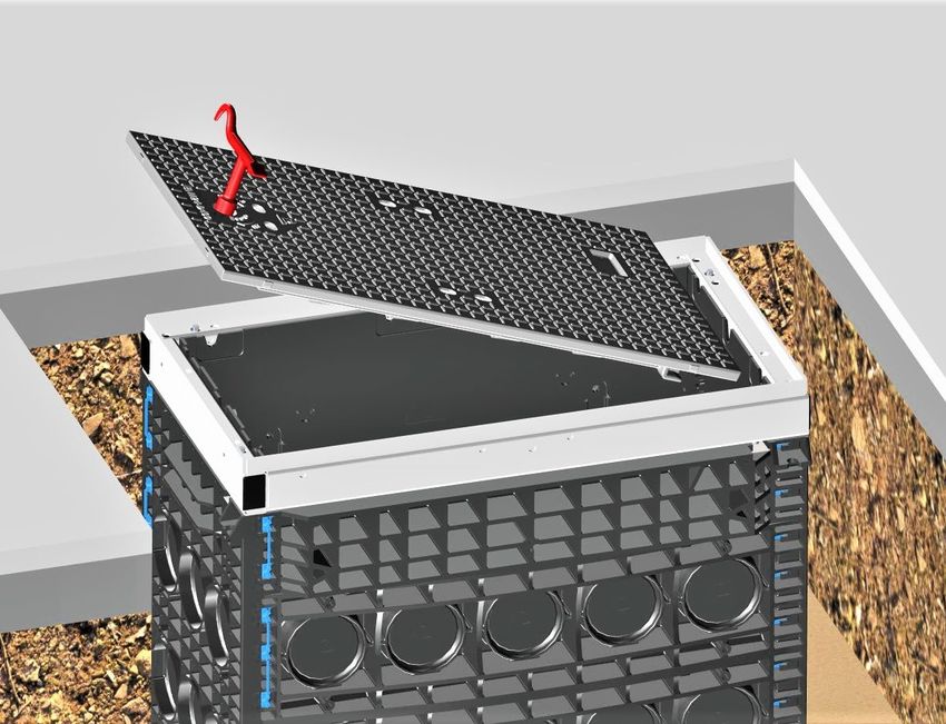
1 Allgemeine Hinweise
Die vorliegende Anleitung ist Bestandteil der Lieferung.

           Achtung !
           Jede Person, die mit dem Aufbau, der Bedienung und Reparatur des
           Produktes befasst ist, muss die Anweisung beachten, gelesen und
           verstanden haben. Für Schäden und Betriebsstörungen, die aus
           Nichtbeachtung der Anweisung resultieren, übernehmen wir keine Haftung.

Im Interesse der Weiterentwicklung behalten wir uns das Recht vor, an einzelnen
Baugruppen und Zubehörteilen Änderungen vorzunehmen, die unter Beibehaltung der
wesentlichen Merkmale zur Steigerung der Sicherheit und Leistungsfähigkeit für
zweckmäßig erachtet werden.

Das Urheberrecht an dieser Anweisung verbleibt bei der Langmatz GmbH.

2 Sicherheitshinweise
Der „Kabelschacht aus Kunststoff“ ist für den stationären und in der Erde versenkten
Einsatz als - Kabelzugschacht,
            - Telekommunikationsverteiler / Glasfaserverteiler,
            - Energieverteilungssystem,
            - System zur Aufnahme von Elektronikkomponenten, bestimmt.

Wenn der Kabelschacht als System zur Aufnahme von Elektronikkomponenten
verwendet wird, ist er nicht für den Betrieb in explosionsgefährdeten Bereichen
geeignet.

Das Produkt entspricht zum Zeitpunkt der Drucklegung dem neuesten Stand der
Technik und wird betriebssicher ausgeliefert. Eigenmächtige Veränderungen, vor allem
an sicherheitsrelevanten Teilen, sind unzulässig.
Vor einer missbräuchlichen Verwendung wird von Seiten der Langmatz GmbH
gewarnt.Arbeiten an den elektrischen oder elektronischen Einbauten dürfen nur von
Elektro- /Glasfaserfachkräften durchgeführt werden.

Für die Installation, den Betrieb und die Wartung der Einbauten ist der Betreiber
verantwortlich.

Der Betreiber hat dafür zu sorgen:
      -   Gefahren für Leib und Leben des Benutzers und Dritter abzuwenden.
      -   Die Betriebssicherheit zu gewährleisten.
      -   Nutzungsausfall und Umweltbeeinträchtigungen durch falsche Handhabung
          auszuschließen.
       -  Dass mit Schutzkleidung gearbeitet wird.
       -
Bei Beschädigungen ist eine Benutzung untersagt. Wenden Sie sich bitte an die
Hotline (siehe Kapitel 13).
           Achtung !
           Beim Aufbau, der Bedienung und der Instandsetzung sind die einschlägigen
           Vorschriften zur Arbeitssicherheit und zum Umweltschutz zu beachten.

                                            3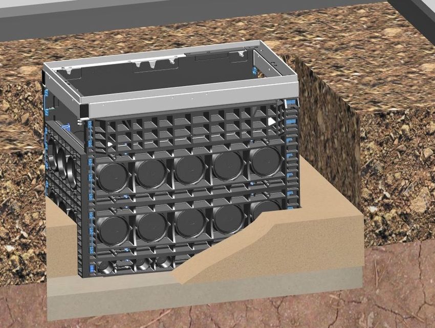
3 Produktbeschreibung
Da es eine Vielzahl an Größen und Ausführungen von Langmatz Kabelschächten
aus Kunststoff gibt, wird diese Anleitung anhand eines Produktbeispiels
Kabelschacht – Lichte Weite (LW) 400 x 800 mm / 750 mm hoch – beschrieben.

3.1 Maße
    (Produktbeispiel LW400 x 800 mm)

             940 mm                                                        560 mm

                                     750 mm

 Abb. 1                                                           Abb. 2

            LW 800 mm
                                     LW 400 mm

 Abb. 3
3.2 Technische Daten – Einzelgestell für Wandmontage

Abmessungen L x B x H:                               940 x 560 x 750 mm

Gesamtgewicht                                        ca. 135 kg

Material Rahmenelemente / Bodenplatte:               Polycarbonat (PC) / Polypropylen (PP)

Material Stahlrahmen:                                Stahl feuerverzinkt

                                                     Stahlguss:        D400 / B125
Varianten Kabelschacht-Abdeckung:                    ausbetoniert:     D400 / B125
                                                     auspflasterbar:   D400 / B125
                                                     Tränenblech:      A15
Varianten Kabelschacht-Verschluss:                   Verriegelung / Verschraubung

                                                 4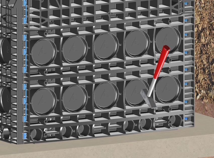
4       Lieferumfang
        (Produktbeispiel LW400 x 800 mm / 750 mm hoch)

                                       1                                 2

                          Abb. 4                          Abb. 5

                                                 Kabelschacht komplett bestehend aus:

                                                 Pos. 1   4x Stufentülle Ø110 mm
                               3
                                                 Pos. 2 18x Doppel-Befestigungs-
                                                            Dübel (Anzahl je nach
                                                            Ausführung)

                                                 Pos. 3   1x Schachtabdeckung
                                                             - Stahlguss
    4                                                        - mit Verriegelung
                                                               (je nach Ausführung)

                                                 Pos. 4   1x Stahlrahmen mit
                                                             Dämpfungsauflage
    5                                                        (Elastomer)

                                                 Pos. 5   1x Kopfrahmen H=140 mm

                                                 Pos. 6   2x Rahmenelement H=220 mm
    6                                                        (Anzahl je nach Ausführung)

                                                 Pos. 7   1x Rahmenelement H=70 mm
    7

                                                 Pos. 8   1x Bodenplatte mit montierten
    8                                                        Befestigungsdübeln (Anzahl
                                                             je nach Ausführung)
Abb. 6

                                           5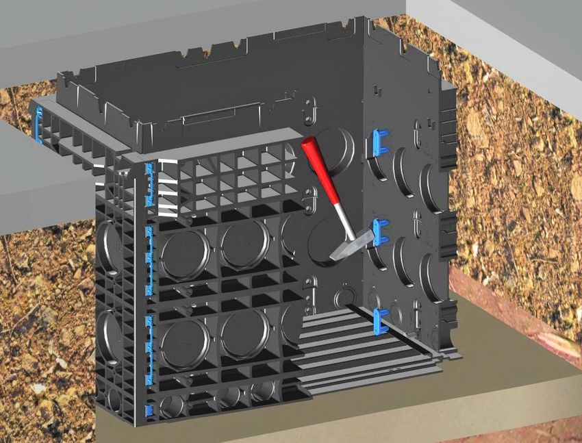
4.1 Benötigte Werkzeuge (nicht im Lieferumfang)
                                              1 Schlüssel mit Aushebehaken
                                                (Typ je nach Ausführung der
                                                Verriegelung. Kann bei Langmatz
                                                bestellt werden).

                                              2 Hammer

                                              3 Sechskant – Schraubendreher SW 5

         1               2           3
Abb. 7

5    Baugrubensohle
5.1 Allgemein
Der Schachteinbau muss durch eine Fachfirma erfolgen.
Vor dem Herstellen einer tragfähigen Baugrubensohle muss eine Beurteilung der
Bodenverhältnisse erfolgen.

-   Für Kabelschächte mit einer Gesamthöhe von kleiner 680 mm, muss der höchste
    Grundwasserstand mindestens 1200 mm unter Oberkante Gelände liegen.

-   Der Schachteinbau muss im „nicht bindigen“ bis „bindigen“ Mischboden erfolgen.

-   Bodenarten der Gruppe G1 bis G3 entsprechend ATV-DVWK-A 127, bzw.
    Bodengruppen GE, GW, GI, SE, SW, SI, GU, GT, SU, ST, GU*, GT*, SU*,ST*, UL
    und UM nach DIN 18196.

              Achtung!
    •    Ein direkter Einbau in die Fahrbahn ist nicht zu empfehlen.

    •    Begründung:
          - Erschwerter Zugang bei laufendem Verkehr
          - Höhere Geräuschentwicklung.

    •    Wird der Kabelschacht dennoch in der Fahrbahn eingebaut,
         empfiehlt Langmatz die Verwendung von „betonierten“
         Kabelschachtabdeckungen.

    Bei der Herstellung der Verkehrsfläche ist die ZTV A-StB 12 zu beachten!

                                          6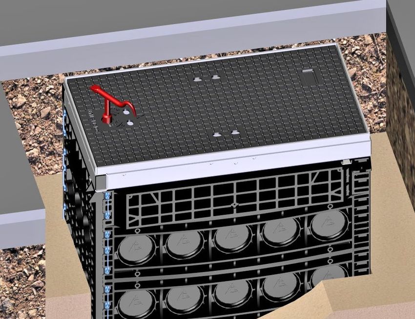
5.2 Baugrubensohle erstellen
Für das Erstellen der Baugrube folgende Unterlagen der Gütegemeinschaft
Leitungstiefbau e.V. beachten:
„Arbeitshinweise für die Ausführung von Arbeiten im Kabelleitungstiefbau“.
Lage und Tiefe der Baugrubensohle auf Einbausituation abstimmen.
Die Oberkante der Kabelschacht-Abdeckung muss ohne Absatz auf dem gleichen
Niveau liegen, wie die umgebende Gelände-Oberkante.
                                                   Situation „A“
                                                   Für begehbare Bereiche:
                                               •   Unterfüllung/Auflager von mindestens
                                                   300 mm Dicke herstellen.
                                               •   Unterfüllung/Auflager muss aus „nicht
                                                   bindigem“ bis „bindigem“ Mischboden
                                                   bestehen (Bodenarten der Gruppe G1
                                                   entsprechend ATV-DVWK-A127).
                                               •   Unterfüllung/Auflager lagenweise
                                                   einbringen und auf DPr ≥ 98%
                                                   verdichten.

Abb. 8

                                                   Situation „B“
                                                   Für befahrbare Bereiche:
                                               •   Aushubsohle nach Anforderung verdichten.
                                               •   Bei Bodenart der Gruppen G1/G2
                                                   entsprechend ATV-DVWK-A 127
                                                   (Bodengruppen GE, GW, GI, SE, SW, SI,
                                                   GU, GT, SU, ST nach DIN 18196):
                                               •   Betontragschicht von mindestens 100 mm
                                                   Dicke herstellen (Stampfbeton,
                                                   Festigkeitsklasse ≥ C8/10).

Abb. 9

                                                   Situation „C“
                                                   Für befahrbare Bereiche:
                                               •   Bei Bodenart der Gruppen G3 entsprechend
                                                   ATV-DVWK-A 127 (Bodengruppen GU*, GT*,
                                                   SU*, ST*, UL, UM nach DIN 18196):
                                               •   Unterfüllung mit Bodenarten der Gruppe G1
                                                   entsprechend ATV-DVWK-A 127 herstellen.
                                                   Dicke mindestens 200 mm. Unterfüllung
                                                   lagenweise einbringen und auf DPr ≥ 98%
                                                   verdichten.
                                               •   Betontragschicht von mindestens 100 mm
                                                   Dicke herstellen (Stampfbeton
                                                   Festigkeitsklasse ≥ C8/10).
Abb. 10

                                           7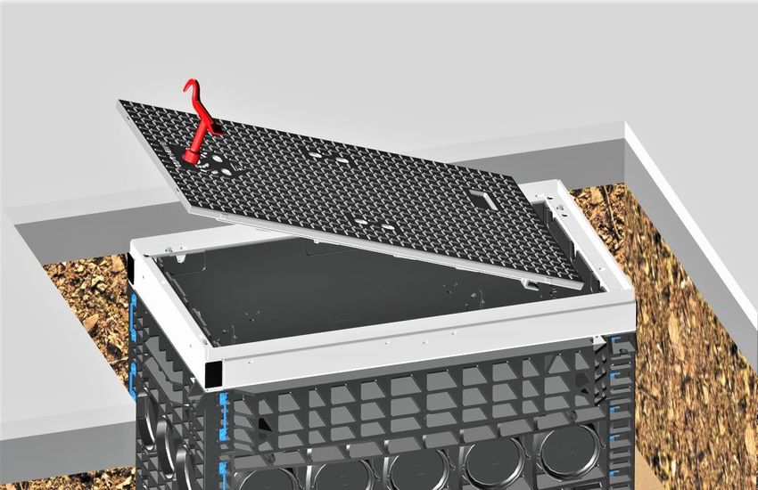
6    Einbau – Kabelschacht
6.1 Grundaufbau
      Einbau Kabelschacht komplett
                                         •   Kompletten Kabelschacht auf
                                             Baugrubensohle setzen oder, je nach
                                             Lieferart, die Einzelteile des Schacht-
                                             Korpus aufbauen
                                             (siehe Abb. 14 - Abb. 16).

                                                    Warnung:
                                         •   Für das Einsetzen des Kabelschachtes
                                             müssen Tragegurte oder dergleichen um
                                             den kompletten Kabelschacht gelegt
                                             werden.
                                         •   Verletzungsgefahr durch Kippen und
                                             Absturz des Kabelschachtes.
Abb. 11
                                         •   Bei Schächten mit werkseitig
                                             angebrachten Kranösen müssen diese
                                             verwendet werden.

          1                                           Warnung:
                                 2       •   Die vorhandenen Aushebeöffnungen in
                                             der Schachtabdeckung (1) dürfen nicht
                                             für das Anheben des Kabelschachtes
                                             verwendet werden.
                                         •   Die Schachtabdeckung (z.B. Guss) kann
                                             herausgerissen und der Stahlrahmen (2)
                                             beschädigt werden.

Abb. 12
      Schachtabdeckung öffnen
                                         •   Für das Öffnen der Schachtabdeckung
                                             den Verschlussriegel mit geeignetem
                                             Schlüssel in „AUF“-Stellung bringen
                                             (90° nach links).
                                         •   Die Schachtabdeckung mit geeignetem
                                             Werkzeug anheben und seitlich
                                             herausziehen.

Abb. 13

                                     8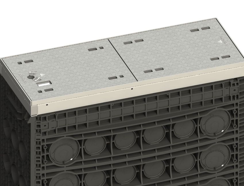
Einbau Kabelschacht - Einzelteile
                                               •   Bodenplatte (4) auf Baugrubensohle
                                                   setzen.
                                   1           •   Rahmenelement H=70 mm (3) auf
                                                   Bodenplatte setzen.
                                               •   Rahmenelemente H=220 mm (2)
                                   2               aufeinander setzen (Anzahl je nach
                                                   Ausführung).
                                               •   Zuletzt Kopfrahmen (1) auf
                                  3                Rahmenaufbau setzen.

                                  4

Abb. 14
      Kabelschacht – Einzelteile verbinden
                                               •   Für das Verbinden der Rahmenelemente
                                                   die beigelegten Doppel-
                                                   Befestigungsdübel (1) von innen
                                                   einschlagen.

                                       1       •   Bodenplatte mit angespritzen
                                                   Befestigungsdübeln (2) am ersten Rahmen
                                                   einschlagen.
                                               •   Alle Rahmenelemente mit Doppel-
                                       2           Befestigungsdübel (1) miteinander
                                                   verbinden.
                                                   Bei Änderung im Schachtaufbau werden
                                                   die Befestigungsdübel mit geeignetem
                                                   Werkzeug von Schacht-Außenseite nach
Abb. 15                                            Schacht-Innenseite durchgeschlagen.
                                               •   Wenn die Befestigungsdübel durch das
                                                   Durchschlagen keine Beschädigungen
                                                   aufweisen, können sie ohne
                                                   Funktionsverlust ein weiteres Mal
                                                   verwendet werden.

                                           9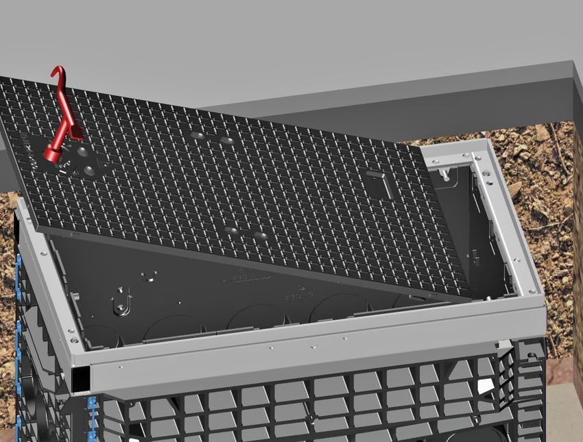
Stahlrahmen montieren
                                           •   Nachdem alle Rahmenelemente fest
                                  1            verbunden sind wird der
                                               Stahlrahmen mit Dämpfungsauflage
                                               (Elastomer) (1) auf Kopfrahmen (2)
                                               aufgesetzt.

                                  2

Abb. 16
      Optional mit Rahmenanker von Stahlrahmen zu Kopfrahmen
                                               Zur Verbindung von Stahlrahmen zu
                                               Kunststoffrahmen kann optional ein
                                               Rahmenanker montiert werden.
                              1                (Gehört nicht zum Standard-
                                               Lieferumfang und muss separat
                                               bestellt werden).

                                           •   Rahmenanker (1) nach beiliegendem
                                               Montagehinweis montieren.

Abb. 17

                                      10
6.2 Schachtaufbau für neue Trassen
Sollbruch für Kabeldurchführungen Ø110 mm / Ø50 mm entfernen
• Gewünschte Anzahl und Lage der
Kabeldurchführung festlegen.
• Entsprechende Sollbruchelemente
Ø110 mm (1) oder Ø50 mm (2) mit
einem Hammer ausschlagen.
1 • Den eventuell entstandenen Grat mit
geeignetem Werkzeug entfernen.
2
Abb. 18
Stufentüllen / Schutzrohrabdichtung montieren
(Beispiel-Darstellung mit Kabel)
• An beiliegender Stufentülle (1) den
benötigten Rohrdurchmesser mit
geeignetem Werkzeug am Sollbruch
1 öffnen.
• Stufentülle wie dargestellt in die Öffnung
(Ø110 mm) im Schacht einsetzen.
Um das Versanden des Kabelschachtes zu
vermeiden, wird bei Verlegung von
Erdkabeln der Einsatz einer Schutzrohr-
2 abdichtung (Ø110 / Ø50 mm) (2) empfohlen.
(Gehört nicht zum Standard-Lieferumfang
und muss separat bestellt werden).
Abb. 19
Micropipe-Rohradapter montieren
(Beispiel-Darstellung)
Micropipe-Rohradapter (1) gehört nicht zum
Standard Lieferumfang und muss separat
1 bestellt werden.
2 • Micropipe-Rohradapter (1) in geöffnete
Kabeldurchführung einsetzen bis die um-
laufende Nut über den umlaufenden Rand
in der Öffnung einrastet.
3 • Micropipe-Verbund / Kabel (4) (max.
Ø 46 mm) durch die geschlitzten
Öffnungen (2) im Micropipe-Rohradapter
in den Schacht führen.
• Beachten: Für Rohre mit max. Ø 50 mm
4 (3) die geschlitzten Öffnungen (2) an
Abb. 20 gekenntzeichneter Lasche greifen
und heraustrennen.
116.3 Optional Schachtaufbau für vorhandene Trassen
Überbaubaren Rahmen für vorhandene Rohre Ø50 mm montieren
• Durch zusammendrücken der beiden
Rastnasen (1) werden die vormontierten
Adapter (2) demontiert.
1
2
Abb. 21
Vorhandene Rohre einsetzen
• Bodenplatte (3) auf Baugrubensohle (4)
setzen.
• Überbaubaren Rahmen (H=70 mm) (2)
2
1 auf Bodenplatte (3) setzen.
• Beachten: Wenn keine
Baugrubensohle vorhanden, so ist
5 diese herzustellen (siehe Kapitel 5).
• Vorhandene Rohre Ø50 mm (1) in die
Aussparungen legen.
• Sollbruch an Adaptern (5) ausschlagen.
• Adapter über die Rohre bis zur
4 Einrastung in die Aussparung drücken.
3
• Weiteren Aufbau der Rahmenelemente
siehe Kapitel 6.1.3 bis 6.1.6.
Abb. 22
Überbaubaren Rahmen für vorhandene Rohre Ø110 mm montieren
• Bodenplatte (4) auf Baugrubensohle
setzen.
1 • Rahmenelement (H=70) mm (3) auf
2 Bodenplatte setzen.
• Überbaubaren Rahmen (H=220 mm)
(1) auf Rahmenelement (H=70 mm) (3)
setzen.
3 • Sollbrüche an Adapterplatten (2)
ausschlagen und über die bestehenden
4 Rohre im Rahmen einsetzen.
• Beachten: Wenn keine
5 Baugrubensohle vorhanden, so ist
diese herzustellen (siehe Kapitel 5).
Abb. 23 • Weiteren Aufbau der Rahmenelemente
siehe Kapitel 6.1.3 bis 6.1.6.
126.4 Baugrube bis Unterkante Oberbau verfüllen
• Baugrube mit verdichtungsfähigem
Material (2) stufenweise nach
ZTV E-StB 09 bis Unterkante
Oberbau (1) verfüllen.
1
2
Abb. 24
6.5 Schachtabdeckung einsetzen
Für einen sachgemäßen Einbau aller
1 Schachtabdeckungen beachten:
• Die Dämpfungsauflage (1) muss
vollständig vorhanden sein.
• Die Dämpfungsauflage darf nicht
beschädigt sein.
• Die Dämpfungsauflage muss vor
dem Einlegen der
Schachtabdeckung gesäubert
werden um einen optimalen Sitz der
Schachtabdeckung zu leisten.
Abb. 25
• Vor dem Einsetzen der
Schachtabdeckung (1) muss der
Verschlussriegel (2) in „AUF“-Stellung
gebracht werden
(90°-Drehung nach links).
1
2
Abb. 26
131 • Schachtabdeckung (2) mit
2 geeignetem Aushebewerkzeug (1)
3 anheben und auf den Stahlrahmen (3)
aufsetzen.
• Hierzu folgenden Schritt in Abb. 28
beachten!
Abb. 27
• Schachtabdeckung mit ca. 100 mm
Abstand vom Stahlrahmen schräg
aufsetzen und bis Anschlag auf die
seitlich angeordneten Haltebolzen (1)
schieben.
1
Abb. 28
• Für das Verriegeln der
Schachtabdeckung den
Verschlussriegel in „ZU“-Stellung
bringen (90°-Drehung nach rechts).
• Das Verschließen wird durch ein
deutliches Einrasten unter dem
Haltebolzen wahrgenommen.
Abb. 29
146.6 Herstellung Oberbau
(Beispiel-Darstellung)
• Oberbau (1) herstellen nach
ZTV A StB 12 (bzw. RStO 2012).
• Bei der Oberfläche Oberbau muss
ein mindestens 550 mm breiter und
140 mm dicker umlaufender
Streifen aus Beton oder
Gussasphalt vorhanden sein
(Asphalttragschicht: mindestens
1
Belastungsklasse Bk 0,3 gemäß
140 mm
RStO 2012).
Der Einbau des Kabelschachtes
ohne Höhenausgleich ist
abgeschlossen.
Abb. 30
157 Optional: Einbau Kabelschacht mit Höhenverstellung
7.1 Bei Verwendung von Vergussmörtel
(ähnlich Typ AzKm)
• Baugrube mit verdichtungsfähigem
1 Material (2) stufenweise nach
ZTV A-StB 12 (bzw. ZTV E-StB 09) bis
Auflagefläche Kopfrahmen (1)
verfüllen.
2
Abb. 31
• Die Gewindestifte mit Innensechskant
1 SW5 für die Höhenverstellungen (1),
sind an allen vier Ecken angebracht.
Abb. 32
• Durch Rechtsdrehung mit dem
Sechskant-Schraubendreher SW5 (1)
1
an allen vier Höhenverstellungen, wird
min. 20 - max. 50 mm
der Stahlrahmen (4) angehoben und
auf die vorgesehene Höhe der
Schachtabdeckung eingestellt.
2 • Bachten:
Idealer Einstellbereich ist mindestens
3 20 mm bis maximal 50 mm.
4 • Beachten:
Der Gewindestift (2) muss immer auf
der Blech – Unterlage (3) aufstehen.
Abb. 33
16• Für das Ausfüllen des Freiraumes
zwischen Kopfrahmen und Stahlrahmen
(3) sollte bauseits ein geeigneter
Schalungsrahmen erstellt werden (2),
um das Wegfließen des Vergussmörtels
1
zu verhindern.
• Innen verhindert eine bestehende
Schalungswand am Kopfrahmen (1) ein
Eindringen des Vergussmörtels.
• Verfüllung nach DIN 18555
3 • Druckfestigkeit >35 N/mm² nach 28
2 Tagen.
• Vergussmörtel: z.B. Typ AzKm
Abb. 34 • Lieferant ist z.B. Firma Ergelit in Alsfeld.
• Beachten:
Für das Ausfüllen darf kein Bauschaum
verwendet werden! Die Tragfähigkeit ist
hier nicht gegeben!
• Alternativ kann ein geeigneter Erdwall
(1) ausgebildet werden, um das
Wegfließen des Vergussmörtels zu
verhindern.
1
Abb. 35
• Schachtabdeckung (1) wieder einlegen
und verriegeln. (Siehe Kapitel 6.5).
1
• Beachten:
Der Kabelschacht kann erst dann
belastet werden, wenn der verwendete
Vergussmörtel die von Hersteller
vorgeschriebene Festigkeit erreicht hat!
• Oberbau herstellen nach ZTV A-StB 12
(Siehe Kapitel 6.6).
Abb. 36
177.2 Bei Verwendung von Trockenmörtel
(ähnlich Typ Kombina 35 S)
• Baugrube mit verdichtungsfähigem
1 Material (3) stufenweise nach
ZTV A-StB 12 (bzw. ZTV E-StB 09) bis
Auflagefläche Kopfrahmen (2)
2 verfüllen ( siehe auch Abb. 31).
• Die Gewindestifte mit Innensechskant
SW5 für die Höhenverstellungen (1),
3 sind an allen vier Ecken angebracht.
Abb. 37
• Durch Rechtsdrehung mit dem
1 Sechskant-Schraubendreher SW5 (1)
an allen vier Höhenverstellungen, wird
min. 20 - max. 50 mm
der Stahlrahmen (4) angehoben und
auf die vorgesehene Höhe der
Schachtabdeckung eingestellt.
2 • Bachten:
Idealer Einstellbereich ist mindestens
3 20 mm bis maximal 50 mm.
4 • Beachten:
Der Gewindestift (2) muss immer auf
der Blech – Unterlage (3) aufstehen.
Abb. 38
• Nach erfolgter Höheneinstellung den
Stahlrahmen (1) abheben und neben
dem Kabelschacht ablegen.
1
Abb. 39
18• Für das Ausfüllen des Freiraumes
zwischen Kopfrahmen und Stahlrahmen,
1
Formstabilen Trockenmörtel aufbringen
(1).
• Innen verhindert eine bestehende
Schalungswand am Kopfrahmen (2) ein
Eindringen des Trockenmörtels.
• Verfüllung nach DIN 18555
• Druckfestigkeit >35 N/mm² nach 28
Tagen.
2 • Trockenmörtel:
z.B. Typ Kombina 35 S oder gleichwertig.
• Beachten:
Abb. 40
Für das Ausfüllen darf kein Bauschaum
verwendet werden! Die Tragfähigkeit ist
hier nicht gegeben!
• Stahlrahmen (1) wieder auf den
Kabelschacht aufsetzen.
• Beachten:
1 Die Gewindestifte (2) der zuvor
eingestellten Höhenverstellung durch den
noch weichen Trockenmörtel (3) drücken
2 bis sie wieder auf der Blechunterlage
aufstehen (siehe Abb. 38 - Pos. 3).
3
Abb. 41
• Schachtabdeckung (1) wieder einlegen
und verriegeln. (Siehe Kapitel 6.5).
1
• Beachten:
Der Kabelschacht kann erst dann
belastet werden, wenn der verwendete
Trockenmörtel die von Hersteller
vorgeschriebene Festigkeit erreicht hat!
• Oberbau herstellen nach ZTV A-StB 12
(Siehe Kapitel 6.6).
Abb. 42
198 Schachtabdeckung 2-teilig
8.1 Schachtabdeckung öffnen
• Für das Öffnen der Schachtabdeckung
den Verschlussriegel mit geeignetem
Schlüssel in „AUF“-Stellung bringen
(90° nach links).
• Die Schachtabdeckung mit geeignetem
Werkzeug anheben und seitlich
herausziehen.
• Die zweite Schachtabdeckung mit
geeignetem Werkzeug seitlich aus den
vier Haltebolzen herausziehen und
anheben.
Abb. 43
8.2 Schachtabdeckung einsetzen und verschließen
• Für das Verschließen muss zuerst die
1 Schachtabdeckung ohne
Verschlussriegel eingelegt werden.
• Schachtabdeckung schräg aufsetzen und
unter die vorhandenen Haltebolzen (1)
schieben.
Abb. 44
• Beachten:
1 3 Vor dem Einsetzen der zweiten
2 Schachtabdeckung (1) muss der
Verschlussriegel (2) in „AUF“-Stellung
gebracht werden (90°-Drehung nach
links).
• Schachtabdeckung mit Verschlussriegel
(1) schräg aufsetzen und unter die bereits
eingelegte Schachtabdeckung (3)
schieben (Übertritt / Untertritt).
• Der Verschlussriegel (2) muss an der
Außenseite des Kabelschachtes liegen.
Abb. 45 • Verschlussriegel in „ZU“-Stellung bringen
(90° nach rechts). Das Verschließen wird
durch ein deutliches Einrasten unter dem
Haltebolzen wahrgenommen.
208.3 Schachtabdeckung 2-teilig – ausbetoniert
einsetzen und verschließen
• Jede Schachtabdeckung verfügt über
zwei Verschlussriegel (1).
• Für das Öffnen der Schachtabdeckung
den Verschlussriegel in „AUF“-Stellung
1 bringen (90° nach links).
• Schachtabdeckung mit geeignetem
Werkzeug nach oben ausheben.
Abb. 46
• Für das Verschließen die
Versschlussriegel in „AUF“-Stellung
bringen.
• Die Schachtabdeckungen mit
geeignetem Werkzeug anheben und in
den Stahlrahmen einlegen.
• Es muss keine Reihenfolge beachtet
1 werden.
• Verschlussriegel in „ZU“- Stellung
bringen (90°-Drehung nach rechts).
• Das Verschließen wird durch ein
deutliches Einrasten unter den
Haltebolzen (1) wahrgenommen.
Abb. 47 • Beachten:
Siehe Kapitel 6.5 Abb. 26
• Einbau der „Schachtabdeckung
2-teilig – ausbetoniert“ ist
abgeschlossen.
Abb. 48
219 Wartung
Maßnahmen Fristen Bemerkungen
Vor dem Öffnen die
Verschlussvorrichtung nur
Schacht-Oberfläche und
Vor jedem Gebrauch. mit dem dafür
Verschlussvorrichtung
vorgesehenen
prüfen und säubern.
Bedienungsschlüssel
öffnen und schließen.
Dämpfungsauflage für Bei Beschädigung
Einmal im Jahr.
Schachtabdeckung prüfen. ersetzen.
Dämpfungsauflage für Mit Besen abfegen ist
Nach jedem Gebrauch.
Schachtabdeckung säubern. ausreichend.
Bei verschraubten Varianten:
Verschluss-Schrauben nur
Verschluss-Schrauben in von Hand eindrehen!
der Schachtabdeckung vor Anti-Size-Paste bei
dem Eindrehen mit Anti- Langmatz erhältlich
Size-Paste behandeln. (Info siehe Kapitel 13 -
Kontakt).
Festschrauben nur mit
geeignetem Werkzeug
(siehe Kapitel 4.1).
Empfohlener Anzieh- Nach jedem Gebrauch.
Drehmoment = 46 Nm.
2210 Sachmängel
Für das Produkt übernimmt die Langmatz GmbH eine Sachmängelhaftung von
24 Monaten im Sinne von § 434 BGB, gerechnet ab Datum des Kaufbeleges.
Im Rahmen der Haftung werden alle Teile, die durch Fabrikations- oder Materialfehler
schadhaft geworden sind, kostenlos ersetzt oder instandgesetzt.
Mängelrügen des Bestellers haben unverzüglich schriftlich zu erfolgen.
Schadensersatzansprüche des Bestellers wegen eines Sachmangels oder gleich aus
welchem Rechtsgrund sind ausgeschlossen.
Von der Haftung ausgeschlossen sind weiterhin Schäden oder Störungen, die durch
- unsachgemäßen Gebrauch,
- auf natürlichen Verschleiß
- auf Eingriff durch Dritte, zurückzuführen sind.
Für Schäden, die durch höhere Gewalt oder Transport entstehen, wird keine Haftung
übernommen.
Durch eine Reparatur aufgrund einer Mängelrüge tritt weder für die ersetzten Teile,
noch für das Produkt eine Verlängerung der Garantiezeit ein.
11 Qualitätsmanagement
Das Qualitätsmanagement - System der Firma Langmatz GmbH ist zertifiziert nach
DIN EN ISO 9001.
12 Haftungsausschluss / Gewährleistung
Die in diesem technischen Dokument beinhalteten Angaben sind nach den
technischen Regeln sowie nach bestem Wissen zutreffend und korrekt dargestellt.
Diese stellen jedoch keine Zusicherung von Eigenschaften dar. Der Betreiber der
Produkte der Langmatz GmbH ist hierbei ausdrücklich dazu verpflichtet, in eigener
Verantwortung über die Tauglichkeit sowie Zweckmäßigkeit für den vorgesehenen
Anwendungsfall zu entscheiden. Die von der Langmatz GmbH zugesicherte
Produkthaftung bezieht sich ausschließlich auf unsere Verkaufs-, Lieferungs- und
Zahlungsbedingungen. Eine Haftung der Langmatz GmbH aufgrund von zufälligen,
indirekten und daraus resultierenden Folgeschäden, sowie Schäden die auf einen
anderen als den beschriebenen und aufgeführten Verwendungszweck des Produktes
zurückzuführen sind, werden ausgeschlossen.
13 Kontakt
Langmatz GmbH
Am Gschwend 10
D - 82467 Garmisch - Partenkirchen
Unsere Hotline: +49 88 21 920 - 137
Telefon: +49 88 21 920 - 0
Email: info@langmatz.de
www.langmatz.de
2370 046 6900 │ Stand 06.07.2021 │ Original - Montageanleitung
24Installation Instructions for Polycarbonate Manholes
Contents

                                                                                   english
1    General information                                                                     3
2    Safety information                                                                      3
3    Product description                                                                     4
     3.1 Dimensions                                                                           4
     3.2 Technical data – Single frame for wall installation                                  4
4    Package includes                                                                        5
     4.1 Required tools (not included)                                                        6
5    Foundation pit base                                                                     6
     5.1 General                                                                              6
     5.2 Preparing the foundation pit base                                                    7
6    Manhole installation                                                                    8
     6.1 Constructing the base                                                                8
                 Installing the complete manhole                                              8
                 Opening the manhole cover                                                    8
                 Installing single manhole parts                                              9
                 Connecting the individual parts of the manhole                               9
                 Installing the steel frame                                                  10
                 Optional frame anchor from steel frame to top frame                         10
     6.2 Manhole structure for new routes                                                    11
                 Removing the predetermined breaking point for Ø110 mm/Ø50 mm cable ducts    11
                 Installing the stepped grommets/protective pipe seals                       11
                 Fitting the micropipe adapter                                               11
     6.3 Optional manhole structure for existing routes                                      12
                 Installing an overbuild frame for existing Ø50 mm pipes                     12
                 Inserting existing pipes                                                    12
                 Installing an overbuild frame for existing Ø110 mm pipes                    12
     6.4 Backfilling the foundation pit up to the lower edge of the top layer                13
     6.5 Inserting the manhole cover                                                         13
     6.6 Constructing the top layer                                                          15
7    Optional: Manhole installation with height adjustment                                   16
     7.1 When using casting mortar                                                           16
     7.2 When using dry mortar                                                               18
8    2-piece manhole cover                                                                   20
     8.1 Opening the manhole cover                                                           20
     8.2 Inserting and closing the manhole cover                                             20
     8.3 Inserting and removing the 2-piece concrete-lined manhole cover                     21
9    Maintenance                                                                             22
10   Material defects                                                                        23
11   Quality management                                                                      23
12   Disclaimer/Warranty                                                                     23
13   Contact                                                                                 23

                                                  2
1 General information
These instructions are supplied with the equipment.
Caution!
Any person involved in the installation, operation and repair of the product
must first read, understand and follow these instructions. We accept no
liability for damage and operating malfunctions caused by failure to comply
with these instructions.
In the interest of further development, we reserve the right to change individual
assemblies and accessories as considered necessary for further safety and
performance improvements, while preserving the main features.
The copyright to these instructions remains with Langmatz GmbH.
2 Safety information
The “polycarbonate manhole” is designed for stationary use underground as a
- cable draw manhole,
- telecommunication distribution point/optical distribution frame,
- energy distribution system,
- system to accommodate electronic components.
When the manhole is used for electronic components, it is not suitable for use in
potentially explosive atmospheres.
The product corresponds to the latest state-of-the-art technology at the time of printing
and is delivered in an operationally safe condition. Unauthorised modifications,
particularly to safety-related parts, are prohibited.
Langmatz GmbH warns against misuse of the product. Work on electrical or electronic
fixtures may only be performed by qualified electricians/optical fibre specialists.
The operator is responsible for installing, operating and maintaining the fixtures.
The operating company is responsible for the following:
- Preventing danger to life and limb of users and third parties.
- Ensuring operational safety.
- Precluding downtime and environmental impact due to incorrect handling.
- Ensuring that protective clothing is worn when working with or on the product.
Do not use the product if it is damaged. Please contact the hotline (see chapter 13).
Caution!
Applicable occupational-safety and environmental-protection regulations
must be observed during installation, operation and maintenance or repair.
33 Product description
Since Langmatz polycarbonate manholes come in a wide variety of sizes and
versions, these instructions are based on one product by way of example:
manhole – clear dimension (CD) 400 x 800 mm / 750 mm high.
3.1 Dimensions
(Example product, CD 400 x 800 mm)
940 mm 560 mm
750 mm
Fig. 1 Fig. 2
CD 800 mm
CD 400 mm
Fig. 3
3.2 Technical data – Single frame for wall installation
Dimensions L x W x H: 940 x 560 x 750 mm
Total weight: Approx. 135 kg
Frame component/base plate material: Polycarbonate (PC)/polypropylene (PP)
Steel frame material: Hot-dip galvanised steel
Cast steel: D400/B125
Concrete-lined: D400/B125
Manhole cover variants: Paveable: D400/B125
Chequered stud A15
plate:
Manhole closure variants: Locking mechanism/screw connection
44 Package includes
(Example product, CD 400 x 800 mm/H 750 mm)
1 2
Fig. 4 Fig. 5
3
Complete manhole comprised of:
Item 1 4x Ø110 mm stepped
grommet
Item 2 18x dual fixing dowel
4 mounting plug (number
depends on design)
Item 3 1x manhole cover
- Cast steel
5 - With locking mechanism
(depending on design)
Item 4 1x steel frame with
damping pad (elastomer)
Item 5 1x top frame H=140 mm
6 Item 6 2x frame component
H=220 mm (number
depends on design)
Item 7 1x frame component
H=70 mm
7
8
Item 8 1x base plate with fitted
fixing dowel mounting
plugs (number depends on
design)
Fig. 6
54.1 Required tools (not included)
1 Key with lifting hook
(type depends on locking mechanism
design. Available to order from
Langmatz).
2 Hammer
3 Size 5 (mm) hexagon screwdriver
1 2 3
Fig. 7
5 Foundation pit base
5.1 General
The manhole must be installed by a specialist company.
Before preparing a load-bearing foundation pit base, the ground conditions must be
assessed.
- For manholes with an overall height less than 680 mm, the highest groundwater
level must be at least 1,200 mm below ground level.
- The manhole must be installed in “non-cohesive” to “cohesive” mixed soils.
- Group G1 to G3 soil types as per ATV-DVWK-A (German Association for Water,
Wastewater and Waste) 127, and/or soil groups GE, GW, GI, SE, SW, SI, GU, GT,
SU, ST, GU*, GT*, SU*,ST*, UL and UM as per DIN 18196.
Caution!
• Direct installation under the carriageway is not recommended.
• Reason:
- More difficult access with moving traffic
- Higher noise development
• If the manhole is installed in the roadway, Langmatz
recommends the use of “concreted” manhole covers.
ZTV A-StB 12 (Supplementary Technical Contract Conditions and Guidelines
for the Construction of Asphalt Roads) must be observed for the construction
of (vehicle) traffic areas!
65.2 Preparing the foundation pit base
When preparing the foundation pit, observe the following documentation from the
Gütegemeinschaft Leitungstiefbau e.V. (Underground Cable Line Construction Quality
Association):
“Procedural instructions for working in underground cable line construction”.
The position and depth of the foundation pit base must be matched to the installation
situation. The upper edge of the manhole cover must lie completely flush with the
surrounding ground level, and must not project.
Situation A
For pedestrian areas:
• Use an underfill/bottom layer at least
300 mm thick.
• The underfill/bottom layer must consist of
“non-cohesive” to “cohesive” mixed soil
(group G1 soil types as per ATV-DVWK-
A127).
• The underfill/bottom layer must be
layered and compacted to DPr ≥ 98%.
Fig. 8
Situation B
For vehicle traffic areas:
• Compact the pit base according to the
requirements.
• For group G1/G2 soil types as per ATV-
DVWK-A 127 (soil groups GE, GW, GI, SE,
SW, SI, GU, GT, SU, ST as per
DIN 18196):
• Use a concrete load-bearing layer at least
100 mm thick (tamped concrete,
strength class ≥ C8/10).
Fig. 9
Situation C
For vehicle traffic areas:
• For group G3 soil types as per ATV-DVWK-
A 127 (soil groups GU*, GT*, SU*, ST*, UL, UM
as per DIN 18196):
• Use an underfill of group G1 soil types
according to ATV-DVWK-A 127. Minimum
thickness 200 mm. The underfill must be
layered and compacted to DPr ≥ 98%.
• Use a concrete load-bearing layer at least
100 mm thick (tamped concrete,
strength class ≥ C8/10).
Fig. 10
76 Manhole installation
6.1 Constructing the base
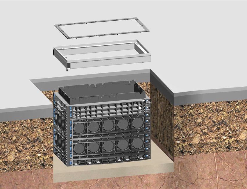
Installing the complete manhole
• Place the complete manhole on the
foundation pit base, or construct the
manhole body depending on how it is
supplied
(see Fig. 14 - Fig. 16).
Warning:
• When inserting the manhole, place slings
or similar around the entire structure.
• If the manhole tips or drops, it may cause
injury.
• Where manholes are factory-fitted with
crane lugs, these must be used.
Fig. 11
1 Warning:
2 • The existing lifting openings in the
manhole cover (1) may not be used to lift
the manhole itself.
• The manhole cover (e.g. cast) could rip
out, damaging the steel frame (2).
Fig. 12
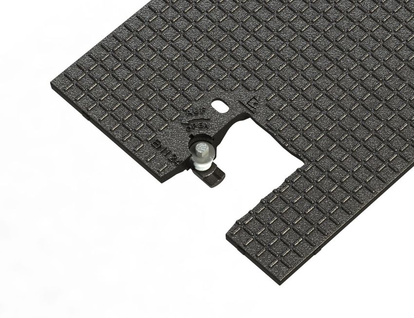
Opening the manhole cover
• To open the manhole cover, turn the lock
catch to the “OPEN” position
(anticlockwise 90°) using the appropriate
key.
• With a suitable tool, lift the manhole
cover and pull it out sideways.
Fig. 13
8Installing single manhole parts
• Place the base plate (4) on the
foundation pit base.
1 • Place the H=70 mm frame component
(3) on the base plate.
• Place the H=220 mm frame
2 components (2) on top of each other
(number based on design).
• Finally, place the top frame (1) on top
3 of the frame structure.
4
Fig. 14
Connecting the individual parts of the manhole
• To connect the frame components, drive
in the supplied dual fixing dowel mounting
plugs (1) from the inside.
• Hammer the base plate and moulded fixing
1 dowel mounting plugs (2) onto the first
frame.
• Connect all the frame components together
with dual fixing dowel mounting plugs (1).
2 When modifying the manhole structure,
drive the fixing dowel mounting plugs
through from the outside to the inside of the
manhole using a suitable tool.
Fig. 15 • If the fixing dowel mounting plugs show
no sign of damage at this point, they can
be reused without any functional
impairment.
9Installing the steel frame
• Once all the frame components are
1 connected, place the steel frame and
(elastomer) damping pad (1) on the
top frame (2).
2
Fig. 16
Optional frame anchor from steel frame to top frame
A frame anchor can optionally be
installed to connect the steel frame to
the plastic frame.
1 (Not included with standard delivery.
Please order separately.)
• Install the frame anchor (1) in
accordance with the enclosed
installation instructions.
Fig. 17
106.2 Manhole structure for new routes
Removing the predetermined breaking point for Ø110 mm/Ø50 mm cable
ducts
• Establish the required number of cable
ducts and where they need to be.
• Knock out the relevant Ø110 mm (1) or
Ø50 mm (2) predetermined breaking
points with a hammer.
1 • Remove any burrs with a suitable tool.
2
Fig. 18
Installing the stepped grommets/protective pipe seals
(Illustrative example with cables)
• Using a suitable tool, open up the required
pipe diameter in the predetermined
breaking points for the stepped grommet
1 supplied (1).
• Insert the stepped grommet into the
opening (Ø110 mm) in the manhole as
shown.
To prevent the manhole from silting up, we
recommend using a protective pipe seal
2 (Ø110/Ø50 mm) (2) when laying grounding
cables. (Not included with standard delivery.
Please order separately.)
Fig. 19
Fitting the micropipe adapter
(Illustrative example)
The micropipe adapter (1) is not included
with standard delivery and must be ordered
1 separately.
2 • Insert the micropipe adapter (1) into the
opened cable duct until the surrounding
groove around the circumference
engages in the opening.
3 • Guide the micropipe bundle/cables (4)
(max. Ø 46 mm) into the manhole
through the slotted openings (2) in the
micropipe adapter.
• Note: For pipes with max. Ø 50 mm (3) ,
4 grip the slotted openings (2) at the
Fig. 20 marked tab and remove.
116.3 Optional manhole structure for existing routes
Installing an overbuild frame for existing Ø50 mm pipes
• The pre-mounted adapters (2) are
removed by pressing together the two
snap lugs (1).
1
2
Fig. 21
Inserting existing pipes
• Place the base plate (3) on the
foundation pit base (4).
• Place the overbuild frame (H=70 mm) (2)
2
1 on the base plate (3).
• Note: If there is no foundation pit base,
one must be created (see chapter 5).
5 • Put the existing Ø50 mm (1) pipes into
the recesses.
• Knock out the predetermined breaking
point on the adapters (5).
• Place the adapters over the pipes and
4 press them into the recesses until they
3
engage.
• For further assembly of the frame
components, see chapters 6.1.3 to 6.1.6.
Fig. 22
Installing an overbuild frame for existing Ø110 mm pipes
• Place the base plate (4) on the
foundation pit base.
1 • Put the frame component (H=70 mm) (3)
2 on the base plate.
• Place the overbuild frame (H=220 mm)
(1) on the frame component (H=70 mm)
(3).
3 • Knock out the predetermined breaking
points on the adapter plates (2) and
4 insert them over the existing pipes in the
frame.
5 • Note: If there is no foundation pit base,
one must be created (see chapter 5).
Fig. 23 • For further assembly of the frame
components, see chapters 6.1.3 to 6.1.6.
126.4 Backfilling the foundation pit up to the lower edge of the top layer
• Backfill the foundation pit in layers
using material suitable for
compacting (2) in accordance with
ZTV E-StB 09 up to the lower edge
of the top layer (1).
1
2
Fig. 24
6.5 Inserting the manhole cover
The following must be observed to
1 ensure proper assembly of any
manhole cover:
• The damping pad (1) must be
complete.
• The damping pad may not be
damaged.
• The damping pad must be cleaned
before the manhole cover is
inserted to ensure that the manhole
cover fits as well as possible.
Fig. 25
• Before inserting the manhole cover (1),
turn the lock catch (2) to the “OPEN”
position
(anticlockwise 90°).
1
2
Fig. 26
131 • Lift the manhole cover (2) using a
2 suitable lifting tool (1) and place on
3 the steel frame (3).
• Note the next step in Fig. 28 for
exactly how to place the cover!
Fig. 27
• Place the manhole cover obliquely
approx. 100 mm from the steel frame
and slide it until it engages with the
retaining bolts on each side (1).
1
Fig. 28
• To lock the manhole cover, turn the
lock catch to the “CLOSED” position
(clockwise 90°).
• When you hear the retaining bolts
click into place, the cover is locked.
Fig. 29
146.6 Constructing the top layer
(Illustrative example)
• Construct the top layer (1) as per
ZTV A StB 12 (and/or RStO 2012).
• At the surface of the top layer, there
must be a strip of concrete or
poured asphalt at least 550 mm
wide and 140 mm thick (asphalt
base layer of at least load class 0.3
according to RStO 2012 (Guidelines
1
for the standardisation of traffic area
140 mm
top layers)).
The manhole assembly without
height adjustment is completed.
Fig. 30
157 Optional: Manhole installation with height adjustment
7.1 When using casting mortar
(similar to AzKm)
• Backfill the foundation pit in layers
1 using material suitable for compacting
(2) in accordance with
ZTV A-StB 12 (and/or ZTV E-StB 09)
up to the contact surface of the top
frame (1).
2
Fig. 31
• The set screws with size 5 (mm)
1 hexagon socket for height adjustment
(1) are attached to all four corners.
Fig. 32
• Turn the size 5 (mm) hexagon
1 screwdriver (1) clockwise at all four
height adjustment points to lift the steel
min. 20 mm - max. 50 mm
frame (4) and adjust it to the intended
manhole cover height.
• Note:
2 The ideal adjustment range is at least
20 mm to maximum 50 mm.
3 • Note:
4 The set screw (2) must always be in
contact with the support plate (3).
Fig. 33
16• To fill in the gap between the top frame
and the steel frame (3), a suitable
formwork frame should be prepared at
the construction site (2) to prevent the
casting mortar from flowing away.
1
• Inside, an existing insulated wall on the
top frame (1) prevents casting mortar
penetration.
• Backfill according to DIN 18555.
• Compressive strength >35 N/mm² after
3 28 days.
2 • Casting mortar: e.g. AzKm
• Supplied e.g. by Ergelit in Alsfeld.
Fig. 34
• Note:
Do not use foam to fill in the gap! It does
not meet load capacity requirements!
• Alternatively, a suitable earth wall (1)
can be formed to prevent the casting
mortar from flowing away.
1
Fig. 35
• Replace and lock the manhole cover
(1). (See chapter 6.5).
1
• Note:
The manhole may only be loaded after
the casting mortar used reaches the
stiffness specified by the manufacturer!
• Build the top layer in accordance with
ZTV A-StB 12 (see chapter 6.6).
Fig. 36
177.2 When using dry mortar
(similar to Kombina 35 S)
• Backfill the foundation pit in layers
1 using material suitable for compacting
(3) in accordance with
ZTV A-StB 12 (and/or ZTV E-StB 09)
2 up to the contact surface of the top
frame (2) (see also Fig. 31).
• The set screws with size 5 (mm)
3 hexagon socket for height adjustment
(1) are attached to all four corners.
Fig. 37
• Turn the size 5 (mm) hexagon
screwdriver (1) clockwise at all four
1
height adjustment points to lift the steel
min. 20 mm - max. 50 mm
frame (4) and adjust it to the intended
manhole cover height.
• Note:
2 The ideal adjustment range is at least
20 mm to maximum 50 mm.
3 • Note:
4 The set screw (2) must always be in
contact with the support plate (3).
Fig. 38
• Once the height has been adjusted,
remove the steel frame (1) and set it
aside next to the manhole.
1
Fig. 39
18• To fill in the gap between the top frame
and the steel frame, apply dimensionally
1
stable dry mortar (1).
• Inside, an existing insulated wall on the
top frame (2) prevents dry mortar
penetration.
• Backfill according to DIN 18555.
• Compressive strength >35 N/mm² after
28 days.
• Dry mortar:
2 e.g., Kombina 35 S or similar.
• Note:
Do not use foam to fill in the gap! It does
Fig. 40
not meet load capacity requirements!
• Place the steel frame (1) back on the
manhole.
1 • Note:
Push the set screws (2) from the earlier
height adjustment through the dry mortar
2 (3) while it is still soft, until they are back
in contact with the support plate (see Fig.
38 - item 3).
3
Fig. 41
• Replace and lock the manhole cover
(1). (See chapter 6.5).
1
• Note:
The manhole may only be loaded after
the dry mortar used reaches the
stiffness specified by the manufacturer!
• Build the top layer in accordance with
ZTV A-StB 12 (see chapter 6.6).
Fig. 42
198 2-piece manhole cover
8.1 Opening the manhole cover
• To open the manhole cover, turn the
lock catch to the “OPEN” position
(anticlockwise 90°) using the
appropriate key.
• With a suitable tool, lift the manhole
cover and pull it out sideways.
• Using a suitable tool, pull the second
manhole cover sideways out of the four
retaining bolts and lift it up.
Fig. 43
8.2 Inserting and closing the manhole cover
• To close the manhole cover, first put it in
1 place without the lock catch.
• Set the manhole cover down obliquely
and slide it under the retaining bolts (1).
Fig. 44
• Note:
1 3
Before inserting the second manhole
2 cover (1), turn the lock catch (2) to the
“OPEN” position (anticlockwise 90°).
• Set down the manhole cover with the lock
catch (1) obliquely and slide it under the
manhole cover (3) already in place
(overlap/underlap).
• The lock catch (2) must be on the outside
of the manhole.
• Turn the catch to the “CLOSED” position
(clockwise 90°). When you hear the
Fig. 45 retaining bolts click into place, the cover is
locked.
208.3 Inserting and removing the 2-piece concrete-lined manhole cover
• Each manhole cover has two lock
catches (1).
• To open the manhole cover, turn the
lock catches to the “OPEN” position
1 (anticlockwise 90°).
• Lift out the manhole cover using a
suitable tool.
Fig. 46
• To close the cover, turn the lock catches
to the “OPEN” position.
• Lift the manhole covers using a suitable
tool and place in the steel frame.
• No particular order needs to be
followed.
• Turn the lock catches to the “CLOSED”
1 position (clockwise 90°).
• When you hear the retaining bolts (1)
click into place, the cover is locked.
• Note:
See chapter 6.5 Fig. 26
Fig. 47
• Installation of the 2-piece concrete-lined
manhole cover is now complete.
Fig. 48
219 Maintenance
Measures Intervals Remarks
Before opening, check and
Only open and close the
clean the manhole surface Before each use. locking mechanism with
and locking mechanism.
the operating key supplied
for this purpose.
Check the manhole cover
Once a year. Replace if damaged.
damping pad.
Clean the manhole cover Sweeping it off with a
After each use.
damping pad. broom is sufficient.
For screwed variants:
Screw in the locking
Treat the locking screws in screws by hand only!
the manhole cover with anti- Anti-seize paste is
seize paste before screwing available from Langmatz
them in. (for info, see chapter 13 -
Contact).
Only tighten with a suitable
tool (see chapter 4.1).
Recommended tightening
torque = 46 Nm. After each use.
2210 Material defects
Langmatz assumes liability for material defects in the product as per Section 434
BGB (German Civil Code) for 24 months, starting from the date on the purchase
receipt.
Within the scope of liability, all parts that become damaged due to manufacturing or
material errors will be replaced or repaired free of charge.
The purchaser must report any deficiency complaints immediately in writing.
Claims for damages by the purchaser due to material defects or whatever legal
reason will not be accepted.
Any damage or failure caused by the following are also excluded from liability:
- Incorrect use,
- Natural wear and tear,
- Intervention by third parties.
We accept no liability for damage caused by force majeure or transport.
Repairs due to a deficiency complaint do not extend the warranty period for the
replaced parts or the product.
11 Quality management
Langmatz GmbH's quality management system is certified to DIN EN ISO 9001.
12 Disclaimer/Warranty
The information in this technical document is presented appropriately and correctly
according to technical regulations and to the best of our knowledge. However, this
does not confer any guarantee of particular characteristics. The operator of the
products supplied by Langmatz GmbH is expressly obliged in this context to decide,
based on his/her own judgement, whether the products are suitable and appropriate
for the application or use being considered. The product liability accepted by
Langmatz GmbH relates exclusively to our conditions of sale, delivery and payment.
Langmatz GmbH accepts no liability due to random, indirect and resultant
consequential damage, as well as any damage attributable to any use of the product
other than for its described and intended purpose.
13 Contact
Langmatz GmbH
Am Gschwend 10
82467 Garmisch-Partenkirchen, Germany
Our hotline: +49 88 21 920 – 137
Telephone: +49 88 21 920 – 0
E-mail: info@langmatz.de
www.langmatz.de
2370 046 6900 │ As of 06/07/2021 │ Translation of the Original Installation Instructions
24Notice d'installation et de montage pour chambres de tirage en polycarbonate
Table des matières

                                                                                                  français
1    Informations d'ordre général                                                                            3
2    Consignes de sécurité                                                                                   3
3    Description du produit                                                                                  4
     3.1   Cotes                                                                                              4
     3.2   Caractéristiques techniques – bâti individuel pour montage mural                                   4
4    Étendue de la fourniture                                                                                5
     4.1   Outils nécessaires (non fournis)                                                                   6
5    Semelle                                                                                                 6
     5.1   Généralités                                                                                        6
     5.2   Réalisation de la semelle                                                                          7
6    Mise en place de la chambre de tirage                                                                   8
     6.1   Structure de base                                                                                  8
                   Mise en place de la chambre de tirage complète                                             8
                   Ouverture du couvercle                                                                     8
                   Mise en place des différents éléments de la chambre de tirage                              9
                   Chambre de tirage – liaison des différents éléments                                        9
                   Montage du cadre en acier                                                                 10
                   Option avec un élément d’ancrage entre le cadre en acier et le cadre de tête              10
     6.2   Structure de la chambre pour nouvelles conduites                                                  11
                   Retirer le masque à briser pour les passe-câbles
                   d’un Ø de 110 mm / Ø de 50 mm                                                             11
                   Montage des douilles étagées / de l’étanchéité du tube de protection                      11
                   Montage de l’adaptateur à micro-conduite                                                  11
     6.3   Montage facultatif de la chambre pour conduites existantes                                        11
                   Montage d’un cadre aménageable en superstructure pour tuyaux
                   existants d’un Ø de 50 mm                                                                 12
                   Mise en place de tuyaux existants                                                         12
                   Montage d’un cadre aménageable en superstructure pour tuyaux
                   existants d’un Ø de 110 mm                                                                12
     6.4   Remblayage de l'excavation jusqu'à l'arête inférieure de la superstructure                        13
     6.5   Mise en place du couvercle                                                                        13
     6.6   Réalisation de la superstructure                                                                  15

7    Option : mise en place de la chambre de tirage avec réglage en hauteur                                  16
     7.1   En cas d’utilisation de mortier de scellement                                                     16
     7.2   En cas d’utilisation de mortier sec                                                               18
8    Couvercle en 2 parties                                                                                  20
     8.1   Ouverture du couvercle                                                                            20
     8.2   Mise en place du couvercle et verrouillage                                                        20
     8.3   Mise en place du couvercle bétonné en 2 parties                                                   21
     et verrouillage                                                                                         21
9    Entretien                                                                                               22
10   Défauts                                                                                                 23
11   Gestion de la qualité                                                                                   23
12   Clause de non-responsabilité / garantie                                                                 23
13   Coordonnées                                                                                             23

                                                         2
1 Informations d'ordre général
La présente notice fait partie des fournitures.
Attention !
Toute personne en charge du montage, de l'utilisation ou de la réparation du
produit doit avoir lu, compris et pris en compte la notice. Nous déclinons
toute responsabilité pour les dommages et dysfonctionnements résultant de
l’inobservation de la notice.
Dans l'intérêt d'éventuelles améliorations, nous nous réservons le droit de procéder à
des modifications sur les différents modules et pièces d'accessoires jugées opportunes
pour l'amélioration de la sécurité et des performances dans le respect des
caractéristiques essentielles.
Les droits d'auteur de la présente notice sont la propriété de Langmatz GmbH.
2 Consignes de sécurité
La « chambre de tirage en polycarbonate » est conçue pour une installation stationnaire
et souterraine en tant que
- chambre de tirage,
- chambre télécom / armoire de distribution pour fibres optiques,
- système de distribution énergétique,
- système pour abriter des composants électroniques.
Si la chambre de tirage est utilisée pour abriter des composants électroniques, elle ne
convient pas à une utilisation dans des zones exposées aux explosions.
Le produit correspond à l'état technique à la date de l’impression ; à la livraison, il est
dans un état de fonctionnement parfaitement sûr. Toute modification réalisée par le
client de son propre chef est proscrite, en particulier si sur des pièces liées à la sécurité.
Langmatz GmbH met en garde contre toute utilisation abusive. Toute intervention sur
des appareillages électriques ou électroniques doit être effectuée exclusivement par
des électriciens qualifiés ou des spécialistes initiés aux fibres optiques.
L’exploitant est seul responsable de l’installation, du fonctionnement et de l’entretien
des appareillages.
L'exploitant doit veiller à :
- parer aux risques pour la vie et l'intégrité physique de l'utilisateur et des tiers.
- garantir la sécurité de fonctionnement.
- exclure la privation de jouissance et les atteintes à l'environnement dues à
une mauvaise manipulation.
- l'utilisation d'équipements de protection individuelle adaptés lors de toute
intervention.
Ne pas utiliser en cas de dommage. Veuillez vous adresser à la hotline (voir chapitre
13).
Attention !
Pour l’installation, l'utilisation et les remises en état, respecter les règles en
vigueur en matière de santé et sécurité au travail, et de protection de
l'environnement.
33 Description du produit
En raison des différentes tailles et versions des chambres de tirage en
polycarbonate de Langmatz, la présente notice décrit l'exemple d’une chambre de
tirage d’une ouverture libre (LW) de 400 x 800 mm / 750 mm de haut.
3.1 Cotes
(exemple de produit LW400 x 800 mm)
940 mm 560 mm
750 mm
Fig. 1 Fig. 2
LW 800 mm
LW 400 mm
Fig. 3
3.2 Caractéristiques techniques – bâti individuel pour montage mural
Dimensions L x l x H : 940 x 560 x 750 mm
Poids total environ 135 kg
Matériau des éléments du cadre / de la
polycarbonate (PC) / polypropylène (PP)
plaque de fond :
Matériau du cadre en acier : acier galvanisé à chaud
fonte d’acier : D400 / B125
Versions de couvercle de chambre de bétonné : D400 / B125
tirage : à paver : D400 / B125
tôle larmée : A15
Versions de fermeture de chambre de
tirage : verrouillage / raccord vissé
4Sie können auch lesen