Betriebsanleitung Operating instructions Notice technique Instrukcja eksploatacji Manual de utilizare
←
→
Transkription von Seiteninhalten
Wenn Ihr Browser die Seite nicht korrekt rendert, bitte, lesen Sie den Inhalt der Seite unten
Betriebsanleitung
Operating instructions
Notice technique
Instrukcja eksploatacji
Manual de utilizare
MS
Copyright 2022 AFRISO-EURO-INDEX GmbH. Alle Rechte vorbehalten.
Lindenstraße 20
74363 Güglingen
Telefon +49 7135 102-0
Service +49 7135 102-211
0035 Telefax +49 7135 102-147
info@afriso.de
www.afriso.com
Version: 05.2022.0
ID: 900.000.0471
Betriebsanleitung
Membran-Sicherheitsventil – Heizung
MS
Copyright 2022 AFRISO-EURO-INDEX GmbH. Alle Rechte vorbehalten.
Lindenstraße 20
74363 Güglingen
Telefon +49 7135 102-0
Service +49 7135 102-211
0035 Telefax +49 7135 102-147
info@afriso.de
www.afriso.com
Version: 05.2022.0
ID: 900.000.0471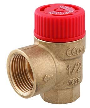
Über diese Betriebsanleitung                                     DE

1   Über diese Betriebsanleitung
    Diese Betriebsanleitung beschreibt das Membran-Sicherheitsventil „MS“ (im
    Folgenden auch „Produkt“). Diese Betriebsanleitung ist Teil des Produkts.
    •   Sie dürfen das Produkt erst benutzen, wenn Sie die Betriebsanleitung
        vollständig gelesen und verstanden haben.
    •   Stellen Sie sicher, dass die Betriebsanleitung für alle Arbeiten an und mit
        dem Produkt jederzeit verfügbar ist.
    •   Geben Sie die Betriebsanleitung und alle zum Produkt gehörenden Unter-
        lagen an alle Benutzer des Produkts weiter.
    •   Wenn Sie der Meinung sind, dass die Betriebsanleitung Fehler, Wider-
        sprüche oder Unklarheiten enthält, wenden Sie sich vor Benutzung des
        Produkts an den Hersteller.
    Diese Betriebsanleitung ist urheberrechtlich geschützt und darf ausschließ-
    lich im rechtlich zulässigen Rahmen verwendet werden. Änderungen vorbe-
    halten.
    Für Schäden und Folgeschäden, die durch Nichtbeachtung dieser Betriebs-
    anleitung sowie Nichtbeachten der am Einsatzort des Produkts geltenden
    Vorschriften, Bestimmungen und Normen entstehen, übernimmt der Herstel-
    ler keinerlei Haftung oder Gewährleistung.

                                                                   MS             2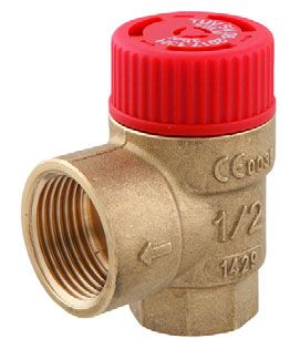
Informationen zur Sicherheit                                  DE

2     Informationen zur Sicherheit
2.1   Warnhinweise und Gefahrenklassen
      In dieser Betriebsanleitung finden Sie Warnhinweise, die auf potenzielle
      Gefahren und Risiken aufmerksam machen. Zusätzlich zu den Anweisungen
      in dieser Betriebsanleitung müssen Sie alle am Einsatzort des Produktes gel-
      tenden Bestimmungen, Normen und Sicherheitsvorschriften beachten. Stel-
      len Sie vor Verwendung des Produktes sicher, dass Ihnen alle Bestimmun-
      gen, Normen und Sicherheitsvorschriften bekannt sind und dass sie befolgt
      werden.
      Warnhinweise sind in dieser Betriebsanleitung mit Warnsymbolen und Sig-
      nalwörtern gekennzeichnet. Abhängig von der Schwere einer Gefährdungs-
      situation werden Warnhinweise in unterschiedliche Gefahrenklassen unter-
      teilt.

                                  WARNUNG
       WARNUNG macht auf eine möglicherweise gefährliche Situation aufmerk-
       sam, die bei Nichtbeachtung einen schweren oder tödlichen Unfall oder
       Sachschäden zur Folge haben kann.

                                   HINWEIS
    HINWEIS macht auf eine möglicherweise gefährliche Situation aufmerksam, die
    bei Nichtbeachtung Sachschäden zur Folge haben kann.

      Zusätzlich werden in dieser Betriebsanleitung folgende Symbole verwendet:
                      Dies ist das allgemeine Warnsymbol. Es weist auf die
                      Gefahr von Verletzungen und Sachschäden hin. Befolgen
                      Sie alle im Zusammenhang mit diesem Warnsymbol
                      beschriebenen Hinweise, um Unfälle mit Todesfolge, Verlet-
                      zungen und Sachschäden zu vermeiden.

                                                                  MS             3
Informationen zur Sicherheit DE
2.2 Bestimmungsgemäße Verwendung
Dieses Produkt eignet sich ausschließlich zum Abblasen folgender Medien
aus geschlossenen Heizungsanlagen (nach EN 12828) zur Absicherung
gegen Drucküberschreitung:
• Wasser
• Wasser-Glykol-Gemische mit maximal 50 % Glykolanteil
• Flüssigkeiten der Fluidgruppe 1 und 2 (Druckgeräterichtlinie, Art. 9), die
die verwendeten Materialien nicht angreifen. Vor dem Einsatz muss die
Beständigkeit der verwendeten Materialien gegen die Flüssigkeit und die
einwandfreie Funktion des Produkts in der Flüssigkeit geprüft werden
Eine andere Verwendung ist nicht bestimmungsgemäß und verursacht
Gefahren.
Stellen Sie vor Verwendung des Produkts sicher, dass das Produkt für die
von Ihnen vorgesehene Verwendung geeignet ist. Berücksichtigen Sie dabei
mindestens folgendes:
• Alle am Einsatzort geltenden Bestimmungen, Normen und Sicherheits-
vorschriften
• Alle für das Produkt spezifizierten Bedingungen und Daten
• Die Bedingungen der von Ihnen vorgesehenen Anwendung
Führen Sie darüber hinaus eine Risikobeurteilung in Bezug auf die konkrete,
von Ihnen vorgesehene Anwendung nach einem anerkannten Verfahren
durch und treffen Sie entsprechend dem Ergebnis alle erforderlichen Sicher-
heitsmaßnahmen. Berücksichtigen Sie dabei auch die möglichen Folgen
eines Einbaus oder einer Integration des Produkts in ein System oder in eine
Anlage.
Führen Sie bei der Verwendung des Produkts alle Arbeiten ausschließlich
unter den in der Betriebsanleitung und auf dem Typenschild spezifizierten
Bedingungen und innerhalb der spezifizierten technischen Daten und in
Übereinstimmung mit allen am Einsatzort geltenden Bestimmungen, Normen
und Sicherheitsvorschriften durch.
MS 4Informationen zur Sicherheit DE
2.3 Vorhersehbare Fehlanwendung
Das Produkt darf insbesondere in folgenden Fällen und für folgende Zwecke
nicht angewendet werden:
• Betrieb bei abgesperrter Abblaseöffnung
• Medien, welche die verwendeten Materialien angreifen
• Medien, welche die Funktion des Produkts beeinträchtigen
• Medien, die zu Verschmutzungen oder Ablagerungen im Produkt führen
• Andere Nenndrücke als auf dem Produkt angegeben
• Über- oder Unterschreitung der zulässigen Mediumstemperatur
2.4 Qualifikation des Personals
Arbeiten an und mit diesem Produkt dürfen nur von Fachkräften vorgenom-
men werden, die den Inhalt dieser Betriebsanleitung und alle zum Produkt
gehörenden Unterlagen kennen und verstehen.
Die Fachkräfte müssen aufgrund ihrer fachlichen Ausbildung, Kenntnisse
und Erfahrungen in der Lage sein, mögliche Gefährdungen vorherzusehen
und zu erkennen, die durch den Einsatz des Produkts entstehen können.
Den Fachkräften müssen alle geltenden Bestimmungen, Normen und
Sicherheitsvorschriften, die bei Arbeiten an und mit dem Produkt beachtet
werden müssen, bekannt sein.
2.5 Persönliche Schutzausrüstung
Verwenden Sie immer die erforderliche persönliche Schutzausrüstung.
Berücksichtigen Sie bei Arbeiten an und mit dem Produkt auch, dass am Ein-
satzort Gefährdungen auftreten können, die nicht direkt vom Produkt ausge-
hen.
2.6 Veränderungen am Produkt
Führen Sie ausschließlich solche Arbeiten an und mit dem Produkt durch, die
in dieser Betriebsanleitung beschrieben sind. Nehmen Sie keine Verände-
rungen vor, die in dieser Betriebsanleitung nicht beschrieben sind.
MS 5Transport und Lagerung DE
3 Transport und Lagerung
Das Produkt kann durch unsachgemäßen Transport und Lagerung beschä-
digt werden.
HINWEIS
UNSACHGEMÄSSE HANDHABUNG
• Stellen Sie sicher, dass während des Transports und der Lagerung des Pro-
dukts die spezifizierten Umgebungsbedingungen eingehalten werden.
• Benutzen Sie für den Transport die Originalverpackung.
• Lagern Sie das Produkt nur in trockener, sauberer Umgebung.
• Stellen Sie sicher, dass das Produkt bei Transport und Lagerung stoßge-
schützt ist.
Nichtbeachtung dieser Anweisungen kann zu Sachschäden führen.
MS 6Produktbeschreibung DE
4 Produktbeschreibung
4.1 Produktidentifikation (Typenschild)
Zur Identifikation Ihres Produkts dient das Typenschild. Das Typenschild
zeigt die folgenden Daten:
A A. Produkt
B B. Eingang x Ausgang
C C. Nenndruck
D D. Anwendungsbereich: Heizung
E E. Artikelnummer
F F. Barcode
Abbildung 1: Beispiel Aufkleber auf der Verpackung
4.2 Funktion
Beim Erwärmen von Wasser in der Anlage dehnt sich die aufgeheizte Flüs-
sigkeit aus. Der Druck in der Anlage steigt. Beim Überschreiten des maximal
zulässigen Drucks der Anlage werden Feder und Membran im Inneren des
eingebauten Produkts zurück gedrückt. Flüssigkeit wird abgeblasen bis der
Druck in der Anlage wieder unter den maximal zulässigen Druck gesunken
ist.
Die Wärmeleistung der abzusichernden Anlage bestimmt die Eingangsgröße
des Produkts.
Die Eingangs- und Ausgangsgröße, der Nenndruck und der Anwendungsbe-
reich sind auf der Kappe des Produkts und auf dem Verpackungsaufkleber-
angegeben.
4.3 Zulassungsdokumente, Bescheinigungen, Erklärungen
Das Produkt entspricht:
• Druckgeräte-Richtlinie (2014/68/EU)
Produkte mit größerem Ventilausgang als Ventileingang besitzen zusätzlich
das:
• Bauteilkennzeichen TÜV SV YY-2017.13.H
YY steht für die Jahreszahl der Zulassung.
MS 7Produktbeschreibung DE
4.4 Technische Daten
Parameter Wert
G 1 /2 G3/4
Allgemeine Daten
Abmessungen (B x H x T) 48 x 60 x 35 mm 52 x 60 x 40 mm
Gewicht Ca. 150 g Ca. 180 g
Kappenfarbe Rot
Nenndruck 1 ... 6 bar
(siehe Kappenbedruckung)
Material
Gehäuse Messing CW617N
Membrane Silikon
Kappe PA6
Umgebungsbedingungen
Mediumstemperatur -20 ... 120 °C
Umgebungstemperatur Lagerung -20 ... 120 °C
Membran-Sicherheitsventile mit Anschlussgewinde
Max. Wärmeleistung des Wärmeer- 50 kW 100 kW
zeugers
MS 8Montage DE
5 Montage
Das Produkt darf erst nach Abschluss aller Rohrmontagearbeiten, Schweiß-
und Lötarbeiten montiert werden.
1. Spülen Sie die Leitungen der Anlage, bevor Sie das Produkt montieren.
5.1 Montage vorbereiten
HINWEIS
UNDICHTHEIT DES PRODUKTS
• Stellen Sie sicher, dass die Leitung des Produkts vor der Montage gespült
wurde. Verunreinigungen und Ablagerungen, beispielsweise Schweißper-
len, Hanf, Metallspäne oder Kalk, machen das Produkt undicht.
Nichtbeachtung dieser Anweisung kann zu Sachschäden führen.
Stellen Sie sicher, dass der Nenndruck des Produkts dem Planwert der
Anlage entspricht.
Stellen Sie sicher, dass die Flüssigkeit in der Anlage der bestimmungsge-
mäßen Verwendung entspricht.
Stellen Sie sicher, dass während der Beheizung Flüssigkeit aus der
Abblaseleitung des Produkts austreten kann.
Stellen Sie sicher, dass das Produkt ohne Absperrung montiert ist.
- Es dürfen keine Absperrungen, Schmutzfänger oder ähnliches einge-
baut sein.
Stellen Sie sicher, dass das Produkt so montiert ist, dass im eingebautem
Zustand keine äußeren Kräfte einwirken.
MS 9Montage DE
5.2 Produkt montieren
Stellen Sie sicher, dass der Pfeil an der Abblaseöffnung des Produkts
(Ventilausgang) mit der Fließrichtung der Flüssigkeit übereinstimmt.
1. Montieren Sie das Produkt so, dass die Flüssigkeit durch die Abblaseöff-
nung ungehindert abfließen kann.
2. Montieren Sie das Produkt am höchsten Punkt des Wärmeerzeugers
oder in seiner unmittelbaren Nähe an der Vorlaufleitung.
- Zwischen Produkt und Wärmeerzeuger darf eine maximal 1 m lange,
gerade Verbindungsleitung installiert sein.
- Der Querschnitt der Verbindungsleitung muss dem Querschnitt des Ein-
gangs des Produkts entsprechen.
3. Ziehen Sie die Anschlüsse beim Verbinden mit maximal 18 Nm an.
- Durch zu starkes Anziehen können sich Risse im Material bilden, was
zu Undichtheiten führen kann.
5.3 Abblaseleitung montieren
WARNUNG
HEISSE FLÜSSIGKEIT
Flüssigkeit in Heizungsanlagen steht unter einem hohen Druck und kann Tem-
peraturen bis über 100 °C erreichen.
• Stellen Sie sicher, das die Abblaseleitung so gelegt ist, dass weder Perso-
nen- noch Sachschäden durch die austretende Flüssigkeit verursacht wer-
den.
Nichtbeachtung dieser Anweisung kann zu Tod, schweren Verletzungen
oder Sachschäden führen.
Stellen Sie sicher, dass die Abblaseleitung zugänglich und sichtbar ist.
Stellen Sie sicher, dass die Ablaufleitung des Trichters den doppelten
Querschnitt des Produkt-Eingangs hat.
MS 10Montage DE
1. Führen Sie die Abblaseleitung mit Gefälle und gemäß der nachstehenden
Tabelle aus.
Länge der Anzahl der Mindestnennweite DN
Abblaseleitung Bögen
Abblaseöffnung Abblaseöffnung
G3/4 G1
≤2m ≤2 20 25
≤4m ≤3 25 32
2. Führen Sie das Leitungsende in einen Ablauf oder Behälter, der den
Gesamtinhalt der Anlage aufnehmen kann.
Die Abblaseöffnung ist durch einen
Pfeil auf dem Ventilkörper gekenn-
zeichnet.
Abbildung 2: Einbau ohne Abblaseleitung (Abbildung links)
Abbildung 3: Einbau mit Abblaseleitung (Abbildung rechts)
MS 11Montage DE
5.4 Produkt tauschen
WARNUNG
HEISSE FLÜSSIGKEIT
Flüssigkeit in Heizungsanlagen steht unter einem hohen Druck und kann Tem-
peraturen bis über 100 °C erreichen.
• Stellen Sie sicher, das die Flüssigkeit abgekühlt ist, bevor Sie das Produkt
tauschen.
• Stellen Sie sicher, dass die Anlage drucklos ist, bevor Sie das Produkt tau-
schen.
Nichtbeachtung dieser Anweisung kann zu Tod, schweren Verletzungen
oder Sachschäden führen.
Stellen Sie sicher, dass der Nenndruck des Produkts dem Planwert der
Anlage entspricht.
Stellen Sie sicher, dass während der Beheizung Flüssigkeit aus der
Abblaseleitung des Produkts austreten kann.
Wenn die Anlage abgekühlt und drucklos ist, können Sie das Produkt tau-
schen.
1. Montieren Sie das Produkt wie in Kapitel "Produkt montieren" beschrie-
ben.
MS 12Inbetriebnahme DE
6 Inbetriebnahme
6.1 Produkt in Betrieb nehmen
1. Bringen Sie in der Nähe der Abblaseleitung oder am Produkt sichtbar ein
Hinweisschild mit folgender Aufschrift an:
“Während der Beheizung muss aus Sicherheitsgründen Wasser aus
der Abblaseleitung austreten können. Nicht verschließen!“
2. Prüfen Sie alle Anschlüsse auf Dichtheit.
3. Spülen Sie vor Inbetriebnahme der Anlage alle Leitungen.
6.2 Funktionsprüfung
1. Stellen Sie einen Behälter bereit, um die Flüssigkeit des Produkts aufzu-
fangen.
2. Schützen Sie anwesende Personen vor der austretenden Flüssigkeit.
3. Öffnen Sie das Produkt durch Drehen der Kappe.
- Flüssigkeit strömt aus.
4. Lassen Sie die Kappe los.
- Es darf keine Flüssigkeit austreten.
7 Betrieb
Stellen Sie sicher, dass während der Beheizung Flüssigkeit aus der
Abblaseleitung des Produkts austreten kann.
1. Prüfen Sie nach dem Auslösen des Produkts die Anlage, bevor die
Anlage wieder in Betrieb genommen wird.
2. Führen Sie eine Funktionsprüfung durch (siehe Kapitel "Funktionsprü-
fung").
MS 13Wartung DE
8 Wartung
8.1 Wartungsintervalle
Zeitpunkt Tätigkeit
halbjährlich Führen Sie eine Funktionsprüfung durch (siehe
Kapitel "Funktionsprüfung").
9 Störungsbeseitigung
Störungen dürfen nur durch den Hersteller behoben werden.
10 Außerbetriebnahme und Entsorgung
Entsorgen Sie das Produkt nach den geltenden Bestimmungen, Normen und
Sicherheitsvorschriften.
1. Demontieren Sie das Produkt (siehe Kapitel "Montage" in umgekehrter
Reihenfolge).
2. Entsorgen Sie das Produk
11 Rücksendung
Vor einer Rücksendung Ihres Produkts müssen Sie sich mit uns in Verbin-
dung setzen (service@afriso.de).
12 Gewährleistung
Informationen zur Gewährleistung finden Sie in unseren Allgemeinen
Geschäftsbedingungen im Internet unter www.afriso.com oder in Ihrem Kauf-
vertrag.
MS 14Ersatzteile und Zubehör DE
13 Ersatzteile und Zubehör
HINWEIS
UNGEEIGNETE TEILE
• Verwenden Sie nur Original Ersatz- und Zubehörteile des Herstellers.
Nichtbeachtung dieser Anweisung kann zu Sachschäden führen.
Produkt
Artikelbezeichnung Wärmeleis- Öffnungs- Art.-Nr. Abbildung
tung druck
Membran-Sicherheits- 50 kW 2,5 bar 42385
-
ventil – Heizung „MS“
G1/2 x G3/4
Membran-Sicherheits- 50 kW 3,0 bar 42390
ventil – Heizung „MS“
G1/2 x G3/4
Membran-Sicherheits- 100 kW 2,5 bar 42386
ventil – Heizung „MS“
G3/4 x G1
Membran-Sicherheits- 100 kW 3,0 bar 42391
ventil – Heizung „MS“
G3/4 x G1
MS 15Anhang DE
14 Anhang
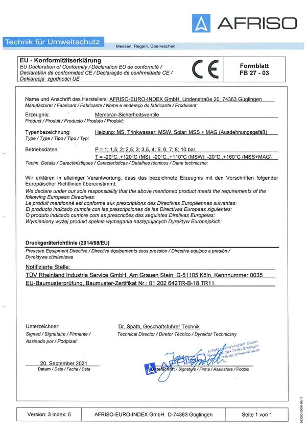
14.1 EU-Konformitätserklärung
MS 16Operating
instructions
Diaphragm safety valve - heating systems
MS
Copyright 2022 AFRISO-EURO-INDEX GmbH. All rights reserved.
Lindenstraße 20
74363 Güglingen
Telephone +49 7135 102-0
Service +49 7135 102-211
0035 Telefax +49 7135 102-147
info@afriso.de
www.afriso.com
Version: 05.2022.0
ID: 900.000.0471About these operating instructions EN
1 About these operating instructions
These operating instructions describe the diaphragm safety valve "MS" (also
referred to as "product" in these operating instructions). These operating
instructions are part of the product.
• You may only use the product if you have fully read and understood these
operating instructions.
• Verify that these operating instructions are always accessible for any type
of work performed on or with the product.
• Pass these operating instructions as well as all other product-related doc-
uments on to all owners of the product.
• If you feel that these operating instructions contain errors, inconsisten-
cies, ambiguities or other issues, contact the manufacturer prior to using
the product.
These operating instructions are protected by copyright and may only be
used as provided for by the corresponding copyright legislation. We reserve
the right to modifications.
The manufacturer shall not be liable in any form whatsoever for direct or con-
sequential damage resulting from failure to observe these operating instruc-
tions or from failure to comply with directives, regulations and standards and
any other statutory requirements applicable at the installation site of the prod-
uct.
MS 2Information on safety EN
2 Information on safety
2.1 Safety messages and hazard categories
These operating instructions contain safety messages to alert you to poten-
tial hazards and risks. In addition to the instructions provided in these oper-
ating instructions, you must comply with all directives, standards and safety
regulations applicable at the installation site of the product. Verify that you are
familiar with all directives, standards and safety regulations and ensure com-
pliance with them prior to using the product.
Safety messages in these operating instructions are highlighted with warning
symbols and warning words. Depending on the severity of a hazard, the
safety messages are classified according to different hazard categories.
WARNING
WARNING indicates a potentially hazardous situation, which, if not avoided,
can result in serious injury or equipment damage.
NOTICE
NOTICE indicates a hazardous situation, which, if not avoided, can result in
equipment damage.
In addition, the following symbols are used in these operating instructions:
This is the general safety alert symbol. It alerts to injury haz-
ards or equipment damage. Comply with all safety instruc-
tions in conjunction with this symbol to help avoid possible
death, injury or equipment damage.
MS 3Information on safety EN
2.2 Intended use
This product may only be used to blow off the following fluids from sealed
heating systems (as per EN 12828) for the purpose of providing protection
against excess pressure:
• Water
• Water/glycol mixtures with a maximum admixture of 50 %
• Liquids of fluid groups 1 and 2 (Pressure Equipment Directive, Article 9)
which do not attack the materials used. Prior to installation, the resistance
of the materials used to the liquid as well as the proper operation of the
product in the liquid must be verified
Any use other than the application explicitly permitted in these operating
instructions is not permitted and causes hazards.
Verify that the product is suitable for the application planned by you prior to
using the product. In doing so, take into account at least the following:
• All directives, standards and safety regulations applicable at the installa-
tion site of the product
• All conditions and data specified for the product
• The conditions of the planned application
In addition, perform a risk assessment in view of the planned application,
according to an approved risk assessment method, and implement the
appropriate safety measures, based on the results of the risk assessment.
Take into account the consequences of installing or integrating the product
into a system or a plant.
When using the product, perform all work and all other activities in conjunc-
tion with the product in compliance with the conditions specified in the oper-
ating instructions and on the nameplate, as well as with all directives, stand-
ards and safety regulations applicable at the installation site of the product.
MS 4Information on safety EN
2.3 Predictable incorrect application
The product must never be used in the following cases and for the following
purposes:
• Operation when the discharge opening is shut off
• Media which attack the materials used
• Media that have an adverse effect on the proper operation of the product
• Media which cause pollution or deposits in the product
• Nominal pressures other than those indicated on the product
• Temperatures in excess of or below the permissible temperature of the
medium
2.4 Qualification of personnel
Only appropriately trained persons who are familiar with and understand the
contents of these operating instructions and all other pertinent product docu-
mentation are authorized to work on and with this product.
These persons must have sufficient technical training, knowledge and expe-
rience and be able to foresee and detect potential hazards that may be
caused by using the product.
All persons working on and with the product must be fully familiar with all
directives, standards and safety regulations that must be observed for per-
forming such work.
2.5 Personal protective equipment
Always wear the required personal protective equipment. When performing
work on and with the product, take into account that hazards may be present
at the installation site which do not directly result from the product itself.
2.6 Modifications to the product
Only perform work on and with the product which is explicitly described in
these operating instructions. Do not make any modifications to the product
which are not described in these operating instructions.
MS 5Transport and storage EN
3 Transport and storage
The product may be damaged as a result of improper transport or storage.
NOTICE
INCORRECT HANDLING
• Verify compliance with the specified ambient conditions during transport or
storage of the product.
• Use the original packaging when transporting the product.
• Store the product in a clean and dry environment.
• Verify that the product is protected against shocks and impact during trans-
port and storage.
Failure to follow these instructions can result in equipment damage.
MS 6Product description EN
4 Product description
4.1 Product identification (nameplate)
The nameplate is used to identify the product. The nameplate shows the fol-
lowing data:
A A. Product
B B. Inlet x outlet
C C. Nominal pressure
D D. Application area: Heating system
E E. Part number
F F. Barcode
Fig. 1: Example of adhesive label on packaging
4.2 Function
When the water in the system heats up, it expands. The pressure in the sys-
tem increases. When the maximum permissible pressure in the system is
exceeded, the spring and the diaphragm integrated in the installed product
are pressed back. Liquid is discharged until the pressure in the system has
dropped below the maximum permissible pressure.
The heat capacity of the system to be safeguarded determines the inlet size
of the product.
The inlet size, the outlet size, the nominal pressure and the application area
are indicated on the cap of the product and on the adhesive label on the pack-
aging.
4.3 Approvals, conformities, certifications
The product complies with:
• Pressure Equipment Directive (2014/68/EU)
Products whose valve outlet is greater than the valve inlet also have:
• Type approval mark TÜV SV YY-2017.13.H
YY represents the year of the approval.
MS 7Product description EN
4.4 Technical data
Parameter Value
G 1 /2 G3/4
General specifications
Dimensions (W x H x D) 48 x 60 x 35 mm 52 x 60 x 40 mm
Weight Approx. 150 g Approx. 180 g
Cap colour Red
Nominal pressure 1 ... 6 bar
(see printing on cap)
Material
Housing Brass CW617N
Diaphragm Silicone
Cap PA6
Ambient conditions
Temperature of the medium -20 ... 120 °C
Ambient temperature storage -20 ... 120 °C
Diaphragm safety valves with connection thread
Max. heat capacity of the heat gen- 50 kW 100 kW
erator
MS 8Mounting EN
5 Mounting
Only mount the product after having completed all pipe assembly work, all
welding work and all soldering work.
1. Flush the lines of the system before installing the product.
5.1 Preparing mounting
NOTICE
LEAKING PRODUCT
• Verify that the pipe of the product has been thoroughly flushed prior to instal-
lation. Impurities and deposits such as weld beads, hemp, metal chips or
limescale cause leaks of the product.
Failure to follow these instructions can result in equipment damage.
Verify that the nominal pressure of the product corresponds to the speci-
fication value of the system.
Verify that the liquid in the system complies with the intended use.
Verify that liquid can escape via the discharge line during heating up.
Verify that the product has been mounted without a shut-off element.
- Do not install shut-off valves, filters or similar equipment.
Verify that the product is mounted in such a way that no external forces
can act on the components after it has been installed.
MS 9Mounting EN
5.2 Mounting the product
Verify that the arrow at the discharge opening of the product (valve outlet)
matches the direction of flow of the liquid.
1. Mount the product in such a way that the liquid can escape via the dis-
charge opening without obstructions.
2. Mount the product at the highest point of the heat generator or in its imme-
diate vicinity at the flow line.
- A straight connection line with a maximum length of 1 m may be
installed between the product and the heat generator.
- The cross section of the connection line must correspond to the cross
section of the inlet of the product.
3. Tighten the connections with a maximum tightening torque of 18 Nm
when making the connections.
- Excessive tightening torque can cause cracks in the material which can
lead to leaks.
5.3 Mounting the discharge line
WARNING
HOT LIQUID
The liquid in heating systems is under high pressure and can have temperatures
of more than 100 °C.
• Verify that the discharge line is installed in such a way that blown off liquid
cannot cause injury or damage.
Failure to follow these instructions can result in death, serious injury or
equipment damage.
Verify that the discharge line is accessible and easy to oversee.
Verify that the drain line of the funnel has twice the cross section of the
inlet of the product.
MS 10Mounting EN
1. Mount the discharge line with a gradient and according to the table below.
Length of the Number of Minimum nominal diameter DN
discharge line elbows
Discharge open- Discharge open-
ing G3/4 ing G1
≤2m ≤2 20 25
≤4m ≤3 25 32
2. Route the end of the discharge line into an outlet or a container that can
hold the total capacity of the system.
The discharge opening is designated
by an arrow on the valve body.
Fig. 2: Installation without discharge line (left)
Fig. 3: Installation with discharge line (right)
MS 11Mounting EN
5.4 Replacing the product
WARNING
HOT LIQUID
The liquid in heating systems is under high pressure and can have temperatures
of more than 100 °C.
• Verify that the heating water has cooled down before replacing the product.
• Verify that there is no pressure in the system before replacing the product.
Failure to follow these instructions can result in death, serious injury or
equipment damage.
Verify that the nominal pressure of the product corresponds to the speci-
fication value of the system.
Verify that liquid can escape via the discharge line during heating up.
When the system has cooled down and is unpressurised, you can replace the
product.
1. Mount the product as described in chapter "Mounting the product".
MS 12Commissioning EN
6 Commissioning
6.1 Commissioning the product
1. Attach a label in the vicinity of the discharge line or to the product with the
following text:
"For safety reasons, water must be able to escape via the discharge
line during heating. Do not shut off!"
2. Check all connections for tightness.
3. Flush all lines of the system prior to commissioning.
6.2 Function test
1. Provide a container to collect the liquid of the product.
2. Protect all persons from escaping liquid.
3. Open the product by turning the cap.
- Liquid escapes.
4. Release the cap.
- No liquid may escape.
7 Operation
Verify that liquid can escape via the discharge line during heating up.
1. If the product has triggered, check the system before recommissioning
the system.
2. Perform a function test (see chapter "Function test").
MS 13Maintenance EN
8 Maintenance
8.1 Maintenance intervals
When Activity
every six months Perform a function test (see chapter "Function
test").
9 Troubleshooting
Malfunctions may only be repaired by the manufacturer.
10 Decommissioning, disposal
Dispose of the product in compliance with all applicable directives, standards
and safety regulations.
1. Dismount the product (see chapter "Mounting", reverse sequence of
steps).
2. Dispose of the product.
11 Returning the device
Get in touch with us before returning your product (service@afriso.de).
12 Warranty
See our terms and conditions at www.afriso.com or your purchase contract
for information on warranty.
MS 14Spare parts and accessories EN
13 Spare parts and accessories
NOTICE
UNSUITABLE PARTS
• Only use genuine spare parts and accessories provided by the manufac-
turer.
Failure to follow these instructions can result in equipment damage.
Product
Product designation Heat capac- Opening Part no. Figure
ity pressure
Diaphragm safety 50 kW 2.5 bar 42385
-
valve – heating sys-
tems "MS" G1/2 x G3/4
Diaphragm safety 50 kW 3.0 bar 42390
valve – heating sys-
tems "MS" G1/2 x G3/4
Diaphragm safety 100 kW 2.5 bar 42386
valve – heating sys-
tems "MS" G3/4 x G1
Diaphragm safety 100 kW 3.0 bar 42391
valve – heating sys-
tems "MS" G3/4 x G1
MS 15Appendix EN
14 Appendix
14.1 EU Declaration of Conformity
MS 16Notice technique
Soupape de sécurité à membrane – chauffage
MS
Copyright 2022 AFRISO-EURO-INDEX GmbH. Tous droits réservés.
Lindenstraße 20
74363 Güglingen
Téléphone +49 7135 102-0
Service clientèle +49 7135 102-211
0035 Téléfax +49 7135 102-147
info@afriso.de
www.afriso.com
Version: 05.2022.0
ID: 900.000.0471La présente notice technique FR
1 La présente notice technique
Cette notice technique contient la description de la soupape de sécurité à
membrane "MS" (dénommé ci-après "produit"). Cette notice technique fait
partie du produit.
• Utilisez le produit seulement après que vous aurez lu et compris intégra-
lement la notice technique.
• Assurez-vous que la notice technique est disponible en permanence pour
toutes les opérations relatives au produit.
• Transmettez la notice technique et toute la documentation relative au pro-
duit à tous les utilisateurs du produit.
• Si vous êtes d'avis que la notice technique contient des erreurs, des
contradictions ou des ambiguïtés, adressez-vous au fabricant avant d'uti-
liser le produit.
Cette notice technique est protégée au titre de la propriété intellectuelle ; elle
doit être utilisée exclusivement dans le cadre autorisé par la loi. Sous réserve
de modifications.
La responsabilité du fabricant ou la garantie ne pourra être engagée pour des
dommages ou dommages consécutifs résultant d'une inobservation de cette
notice technique ou des directives, règlements et normes en vigueur sur le
lieu d'installation du produit.
MS 2Informations sur la sécurité FR
2 Informations sur la sécurité
2.1 Consignes de sécurité et classes de risques
Cette notice technique contient des consignes de sécurité destinées à attirer
l'attention sur les dangers et les risques. Outre les instructions contenues
dans cette notice technique, il faut vous assurer de l'observation de tous les
règlements, normes et consignes de sécurité en vigueur sur le lieu d'installa-
tion du produit. Avant d'utiliser le produit assurez-vous que tous les règle-
ments, normes et consignes de sécurité sont connus et respectés.
Dans cette notice technique les consignes de sécurité sont identifiables à
l'aide de symboles de mise en garde et de mots d'avertissement. En fonction
de la gravité du risque les consignes de sécurité sont réparties dans diffé-
rentes classes de risques.
AVERTISSEMENT
AVERTISSEMENT signale une situation potentiellement dangereuse qui, si
elle n'est pas évitée, peut entraîner la mort ou des blessures graves ou un
dommage matériel.
AVIS
AVIS signale une situation potentiellement dangereuse qui, si elle n'est pas évi-
tée, peut entraîner un dommage matériel.
Les symboles suivants sont également utilisés dans cette notice technique :
Ceci est le pictogramme général de mise en garde. Il signale
un risque de blessure et de dommage matériel. Respectez
toutes les consignes de sécurité afin d'éviter des accidents
mortels, des blessures ou des dommages matériels.
MS 3Informations sur la sécurité FR
2.2 Usage normal
Le produit est destinée exclusivement à la décharge des liquides suivants
des installations de chauffage fermées (selon EN 12828) dans le but de les
protéger contre le dépassement de pression :
• Eau
• Mélange d'eau-glycol, mélange max. 50 %
• Liquides du groupe de fluides 1 et 2 (directive équipements sous pres-
sion, art. 9) qui n'attaquent pas les matériaux utilisés. Avant d'utiliser le
produit, il faut vérifier la résistance des matériaux au liquide ainsi que le
bon fonctionnement de la soupape de sécurité dans le liquide.
Toute autre utilisation n'est pas conforme et cause des risques.
Avant d'utiliser le produit, assurez-vous que le produit est adapté à l'usage
que vous prévoyez. À cet effet, tenez compte au moins de ce qui suit :
• Tous les règlements, normes et consignes de sécurité sur le lieu d'instal-
lation
• Toutes les conditions et données spécifiées pour le produit
• Toutes les conditions d'application que vous prévoyez
En outre effectuez une évaluation des risques portant sur l'application
concrète que vous prévoyez à l'aide d'un procédé reconnu et prenez toutes
les mesures de sécurité nécessaires correspondant au résultat. Prenez
aussi en compte les conséquences possibles du montage ou de l'intégration
du produit dans un système ou une installation.
Pendant l'utilisation du produit effectuez toutes les opérations exclusivement
dans les conditions spécifiées dans cette notice technique et sur la plaque
signalétique, conformément aux données techniques spécifiées et en accord
avec tous les règlements, normes et consignes de sécurité en vigueur sur le
lieu d'installation.
MS 4Informations sur la sécurité FR
2.3 Utilisation non conforme prévisible
Le produit ne doit, en particulier, pas être utilisé dans les cas suivants :
• Fonctionnement quand l'orifice de décharge est bloqué
• Liquides attaquant les matériaux utilisés
• Liquides susceptibles de nuire au fonctionnement du produit
• Liquides entraînant une contamination ou des dépôts dans le produit
• Autres pressions de service que celles indiquées sur le produit
• Dépassement des limites inférieures ou supérieures admissibles de tem-
pérature du liquide
2.4 Qualification du personnel
Seul le personnel dûment qualifié est autorisé à travailler sur le produit et
avec celui-ci après qu'il aura connu et compris le contenu de cette notice
technique, ainsi que toute la documentation faisant partie du produit.
S'appuyant sur sa formation spécialisée, ses connaissances et ses expé-
riences, le personnel qualifié doit être en mesure de prévoir et reconnaître les
dangers qui peuvent être causés par l'utilisation du produit.
Tous les règlements, normes et consignes de sécurité en vigueur sur le lieu
d'installation doivent être connus du personnel qualifié travaillant sur le pro-
duit et avec celui-ci.
2.5 Équipement de protection individuelle
Utilisez toujours l'équipement de protection individuel requis. En travaillant
sur le produit et avec celui-ci, tenez compte des dangers susceptibles de se
présenter sur le lieu d'installation lesquels n'émanent pas directement du
produit.
2.6 Modification du produit
En travaillant sur le produit et avec celui-ci, effectuez exclusivement les opé-
rations décrites dans cette notice technique. N'effectuez pas de modifica-
tions non décrites dans cette notice technique.
MS 5Transport et stockage FR
3 Transport et stockage
Un transport et un stockage inadéquats risquent de causer des dommages
au produit.
AVIS
MANUTENTION INAPPROPRIÉE
• Assurez-vous que les conditions ambiantes spécifiées sont respectées pen-
dant le transport et le stockage.
• Utilisez l'emballage d'origine pour le transport.
• Stockez le produit dans un lieu sec et propre.
• Assurez-vous que le produit est à l'abri des chocs pendant le transport et le
stockage.
La non-observation de ces instructions peut causer des dommages maté-
riels.
MS 6Description du produit FR
4 Description du produit
4.1 Identification du produit (plaque signalétique)
La plaque signalétique permet d'identifier le produit. La plaque signalétique
contient les données suivantes :
A A. Produit
B B. Entrée x sortie
C C. Pression nominale
D D. Domaine d'application : Chauf-
fage
E
E. Référence
F
F. Code barres
Figure 1: Exemple d'étiquette autocollant sur l'emballage
4.2 Fonctionnement
Lors de l'élévation de sa température, l'eau dans une installation se dilate. La
pression dans l'installation augmente. En cas de dépassement de la pression
maximale autorisée dans l'installation, le ressort et la membrane, situés à
l'intérieur du produit monté, sont repoussés. Le liquide s'échappe jusqu'à ce
que la pression de l'installation descende en dessous de la pression maxi-
male autorisée.
La puissance calorifique de l'installation à protéger détermine la taille du rac-
cord d'entrée du produit.
La taille du raccord d'entrée, la taille du raccord de sortie, la pression nomi-
nale et le domaine d'application sont indiquées sur le capuchon et sur l'éti-
quette autocollant sur l'emballage.
4.3 Agréments, certificats, déclarations
Le produit est conforme à :
• Directive équipements sous pression (2014/68/UE)
Les produits dont la taille de sortie est supérieure à la taille d'entrée pos-
sèdent en plus :
• Marque d'homologation TÜV SV YY-2017.13.H
YY représente l'année de l'homologation.
MS 7Description du produit FR
4.4 Caractéristiques techniques
Paramètre Valeur
G 1 /2 G3/4
Caractéristiques générales
Dimensions (L x H x P) 48 x 60 x 35 mm 52 x 60 x 40 mm
Poids Env. 150 g Env. 180 g
Couleur capuchon Rouge
Pression nominale 1 ... 6 bar
(voir impression sur le capuchon)
Matériau
Boîtier Laiton CW617N
Membrane Silicone
Capuchon PA6
Conditions ambiantes
Température du liquide -20 ... 120 °C
Température ambiante stockage -20 ... 120 °C
Soupapes de sécurité à membrane avec filetage de raccordement
Puissance calorifique max. du géné- 50 kW 100 kW
rateur de chaleur
MS 8Montage FR
5 Montage
Le produit ne doit être installé qu'après l'achèvement de tous les travaux de
montage de tuyauterie, de soudage et de brasage.
1. Rincez les conduites de l'installation avant de monter le produit.
5.1 Préparation du montage
AVIS
INÉTANCHÉITÉ DU PRODUIT
• Assurez-vous que la conduite du produit a été rincée avant le montage. Les
impuretés et les dépôts telles que perles de soudure, le chanvre, les copeaux
métalliques ou les dépôts calcaires nuisent à l'étanchéité du produit.
La non-observation de ces instructions peut causer des dommages maté-
riels.
Assurez-vous que la pression nominale du produit correspond aux para-
mètres prévus pour l'installation.
Assurez-vous que le liquide dans le système correspond à l'usage nor-
male.
Vérifiez qu'au cours du chauffage le liquide puisse s'échapper par le la
conduite de décharge du produit.
Assurez-vous que le produit est monté sans arrêt.
- Ne montez ni robinets d'arrêt ni filtres ni dispositifs similaires.
Montez le produit de sorte qu'aucune force extérieure ne s'exerce sur les
composants montés.
MS 9Montage FR
5.2 Montage du produit
Assurez-vous que la flèche sur l'orifice de décharge du produit (sortie de
la soupape) concorde avec la direction d'écoulement.
1. Montez le produit de sorte que le liquide puisse s'écouler facilement par
l'orifice de décharge.
2. Montez le produit au point le plus élevé du générateur de chaleur ou à
proximité immédiate de celui-ci sur la conduite de départ.
- Entre le produit et le générateur de chaleur, la conduite de raccorde-
ment installée doit avoir une longueur maximale d'1 mètre sans coudes.
- La section de la conduite de raccordement doit être égale à la section
d'entrée du produit.
3. Le couple de serrage maximal des raccordements est de 18 Nm.
- Un couple de serrage supérieur risque de provoquer des fissures et des
fuites dans l'installation.
5.3 Montage de la conduite de décharge
AVERTISSEMENT
LIQUIDE CHAUD
Le liquide dans les installations de chauffage est sous haute pression et peut
atteindre des températures dépassant 100 °C.
• Assurez-vous que la conduite de décharge est posée de sorte que l'échap-
pement du liquide ne peut pas causer de dommages corporels ou matériels.
La non-observation de ces instructions peut entraîner la mort ou des bles-
sures graves ou un dommage matériel.
Assurez-vous que la conduite de décharge est accessible et visible en
tout temps.
Assurez-vous que la section de la conduite d'écoulement de la trémie est
double de celle-ci de l'entrée du produit.
MS 10Montage FR
1. Posez la conduite de décharge en pente et selon le tableau ci-dessous.
Longueur de la Nombre de Diamètre nominal minimum DN
conduite de coudes
Orifice de Orifice de
décharge
décharge G3/4 décharge G1
≤2m ≤2 20 25
≤4m ≤3 25 32
2. Posez l'extrémité de la conduite de décharge dans un drain ou un réci-
pient capable de contenir le contenu total de l'installation.
L'orifice de décharge est marqué
d'une flèche sur le corps de la sou-
pape.
Figure 2: Montage sans conduite de décharge (figure à gauche)
Figure 3: Montage avec conduite de décharge (figure à droite)
MS 11Montage FR
5.4 Remplacer le produit
AVERTISSEMENT
LIQUIDE CHAUD
Le liquide dans les installations de chauffage est sous haute pression et peut
atteindre des températures dépassant 100 °C.
• Assurez-vous que l'eau de chauffage a suffisamment refroidi avant de rem-
placer le produit.
• Vérifiez l'absence de pression dans le système avant de remplacer le pro-
duit.
La non-observation de ces instructions peut entraîner la mort ou des bles-
sures graves ou un dommage matériel.
Assurez-vous que la pression nominale du produit correspond aux para-
mètres prévus pour l'installation.
Vérifiez qu'au cours du chauffage le liquide puisse s'échapper par le la
conduite de décharge du produit.
Si l'installation est refroidie et dépressurisée, vous pouvez remplacer le pro-
duit.
1. Montez le produit comme décrit dans le chapitre "Montage du produit".
MS 12Mise en service FR
6 Mise en service
6.1 Mise en service du produit
1. À proximité de la conduite de décharge ou sur le produit, apposez un pan-
neau de signalisation bien visible portant l'inscription suivante :
" Pendant le chauffage il faut que le liquide puisse s'écouler de la
conduite de décharge pour des raisons de sécurité. Ne pas
obturer ! "
2. Vérifiez l'étanchéité de tous les raccords.
3. Purgez les conduites de l'installation avant la mise en service.
6.2 Test de fonctionnement
1. Préparez un récipient adapté pour récupérer le liquide écoulé par le pro-
duit.
2. Protégez les personnes présentes des éclaboussures de liquide éven-
tuelles.
3. Ouvrez le produit en tournant le capuchon.
- Le liquide s'écoule.
4. Relâchez le capuchon.
- Aucun liquide ne doit s'écouler.
7 Service
Vérifiez qu'au cours du chauffage le liquide puisse s'échapper par le la
conduite de décharge du produit.
1. Après un déclenchement du produit, vérifiez l'installation avant de
remettre l'installation en service.
2. Effectuez un test de fonctionnement (voir chapitre "Test de fonctionne-
ment").
MS 13Maintenance FR
8 Maintenance
8.1 Intervalles de maintenance
Quand Opération
Tous les six mois Effectuez un test de fonctionnement (voir
chapitre "Test de fonctionnement").
9 Suppression des dérangements
Les dérangements doivent être éliminés uniquement par le fabricant.
10 Mise hors service et élimination
Pour éliminer le produit, conformez-vous aux règlements, normes et
consignes de sécurité en vigueur.
1. Démontez le produit (voir chapitre "Montage", effectuez les opérations en
ordre inverse).
2. Éliminez le produit.
11 Retour
Avant de retourner le produit, il faut que vous preniez contact avec nous (ser-
vice@afriso.de).
12 Garantie
Les informations sur la garantie figurent dans nos "Conditions générales de
vente" sur le site www.afriso.com ou dans votre contrat d'achat.
MS 14Pièces détachées et accessoires FR
13 Pièces détachées et accessoires
AVIS
PIÈCES INADAPTÉES
• N'utilisez que des accessoires et des pièces détachées d'origine provenant
du fabricant.
La non-observation de ces instructions peut causer des dommages maté-
riels.
Produit
Désignation de Puissance Pression Réfé- Figure
l'article calorifique d'ouver- rence
ture
Soupape de sécurité à 50 kW 2,5 bars 42385
-
membrane – chauf-
fage "MS" G1/2 x G3/4
Soupape de sécurité à 50 kW 3,0 bars 42390
membrane – chauf-
fage "MS" G1/2 x G3/4
Soupape de sécurité à 100 kW 2,5 bars 42386
membrane – chauf-
fage "MS" G3/4 x G1
Soupape de sécurité à 100 kW 3,0 bars 42391
membrane – chauf-
fage "MS" G3/4 x G1
MS 15Annexe FR
14 Annexe
14.1 Déclaration de conformité UE
MS 16Instrukcja
eksploatacji
Membranowy zawór bezpieczeństwa do instalacji
grzewczych
MS
Copyright 2022 AFRISO-EURO-INDEX GmbH. Wszystkie prawa zastrzeżone.
Lindenstraße 20
74363 Güglingen
telefon +49 7135 102-0
serwis +49 7135 102-211
0035 telefaks +49 7135 102-147
info@afriso.com
www.afriso.com
Version: 05.2022.0
ID: 900.000.0471Objaśnienia do niniejszej instrukcji eksploatacji DE
1 Objaśnienia do niniejszej instrukcji eksploatacji
Niniejsza instrukcja eksploatacji opisuje membranowy zawór bezpieczeństwa
„MS“ (poniżej zwany także „produktem“). Niniejsza instrukcja eksploatacji jest
częścią produktu.
• Produkt wolno użytkować dopiero po całkowitym przeczytaniu i pełnym zro-
zumieniu instrukcji eksploatacji.
• Należy upewnić się, że instrukcja eksploatacji jest dostępna w każdej chwili
podczas prac wykonywanych przy produkcie oraz z jego pomocą.
• Należy przekazać instrukcję eksploatacji oraz wszystkie dokumenty nale-
żące do produktu wszystkim użytkownikom produktu.
• W razie wystąpienia opinii, że instrukcja eksploatacji zawiera błędy, sprzecz-
ności lub niejasności, należy skontaktować się z producentem przed odda-
niem produktu do użytkowania.
Niniejsza instrukcja eksploatacji jest chroniona prawem autorskim, wobec
czego wolno ją stosować wyłącznie w ramach obowiązującego prawa. Zmiany
zastrzeżone.
Producent nie przejmuje żadnej odpowiedzialności lub gwarancji za uszkodze-
nia lub ich konsekwencje wynikające z nieprzestrzegania niniejszej instrukcji
eksploatacji oraz przepisów, warunków i norm obowiązujących w miejscu użyt-
kowania produktu.
2Informacje na temat bezpieczeństwa DE
2 Informacje na temat bezpieczeństwa
2.1 Wskazówki ostrzegawcze i klasy zagrożenia
Niniejsza instrukcja eksploatacji zawiera wskazówki ostrzegawcze zwracające
uwagę na potencjalne zagrożenia oraz ryzyka. Poza zaleceniami zawartymi w
niniejszej instrukcji eksploatacji trzeba przestrzegać wszystkich warunków,
norm oraz przepisów bezpieczeństwa obowiązujących w miejscu użytkowania
produktu. Przed zastosowaniem produktu należy upewnić się, że wszystkie
warunki, normy oraz przepisy bezpieczeństwa są użytkownikowi znane i prze-
strzegane.
Wskazówki ostrzegawcze są oznakowane w niniejszej instrukcji eksploatacji za
pomocą symboli ostrzegawczych oraz haseł ostrzegawczych. Wskazówki
ostrzegawcze są podzielone na różne klasy zagrożenia w zależności od stopnia
ciężkości sytuacji zagrożenia.
OSTRZEŻENIE
OSTRZEŻENIE zwraca uwagę na ewentualnie niebezpieczną sytuację, która w
przypadku nieprzestrzegania może spowodować ciężki lub śmiertelny wypa-
dek wypadek lub powstanie szkód materialnych.
WSKAZÓWKA
WSKAZÓWKA zwraca uwagę na ewentualnie niebezpieczną sytuację, która w
przypadku nieprzestrzegania może spowodować powstanie szkód material-
nych.
W niniejszej instrukcji eksploatacji stosowane są dodatkowo następujące sym-
bole:
To jest ogólny symbol ostrzegawczy. Wskazuje on na wystę-
powanie niebezpieczeństwa obrażeń oraz szkód material-
nych. Należy przestrzegać wszystkich wskazówek opisanych
w powiązaniu z tym symbolem ostrzegawczym w celu unik-
nięcia wypadków ze skutkiem śmiertelnym, obrażeń oraz
szkód materialnych.
3Informacje na temat bezpieczeństwa DE
2.2 Stosowanie zgodne z przeznaczeniem
Niniejszy produkt przeznaczony jest wyłącznie do wyrzutu wymienionych poni-
żej mediów z zamkniętych instalacji grzewczych (według normy EN 12828) w
celu zabezpieczenia instalacji przed nadmiernym wzrostem ciśnienia:
• wody,
• mieszanin wody i glikolu z domieszką maksymalnie 50 %.
• cieczy należących do grupy 1 i 2 (dyrektywa o urządzeniach ciśnieniowych,
artykuł 9), które nie wpływają niszcząco na zastosowane materiały. Przed
użyciem trzeba sprawdzić odporność zastosowanych materiałów na ciecz
oraz poprawność działania produktu w kontakcie z cieczą.
Inny rodzaj zastosowania nie jest zgodny z przeznaczeniem i powoduje
powstawanie zagrożeń.
Przed zastosowaniem produktu należy upewnić się, że produkt nadaje się do
przewidzianego przez użytkownika rodzaju zastosowania. W tym celu trzeba
uwzględnić co najmniej następujące wymogi:
• wszystkie warunki, normy oraz przepisy bezpieczeństwa obowiązujące w
miejscu użytkowania produktu,
• wszystkie warunki i dane przewidziane w specyfikacji produktu,
• warunki przewidziane dla planowanego przez użytkownika zastosowania.
Ponadto należy przeprowadzić według uznanej procedury ocenę ryzyka w
odniesieniu do konkretnego zastosowania przewidzianego przez użytkownika
oraz podjąć wszelkie odpowiednie działania na rzecz bezpieczeństwa zgodnie
z wynikiem procedury oceny ryzyka. Należy też przy tym uwzględnić możliwe
konsekwencje wynikające z zabudowy lub integracji produktu w systemie lub
instalacji.
Podczas użytkowania produktu wszystkie prace należy przeprowadzać
wyłącznie w warunkach wyszczególnionych w instrukcji eksploatacji oraz na
tabliczce znamionowej, w ramach danych technicznych zawartych w specyfi-
kacji oraz w zgodzie ze wszystkimi warunkami, normami i przepisami bezpie-
czeństwa obowiązującymi w miejscu użytkowania produktu.
4Sie können auch lesen