Typ 2030 Manuel d'utilisation Operating Instructions - Betriebsanleitung - Version: 01/2021 - Schubert & Salzer
←
→
Transkription von Seiteninhalten
Wenn Ihr Browser die Seite nicht korrekt rendert, bitte, lesen Sie den Inhalt der Seite unten

Betriebsanleitung

                    Operating Instructions

                    Manuel d'utilisation

                      Typ 2030

Version: 01/2021
                        Bunsenstrasse             D-85053 Ingolstadt
M2030-def.doc           Tel: (0841) 9654-0        Fax: (0841) 9654-590
Art.-Nr: 111 2030       www.schubert-salzer.com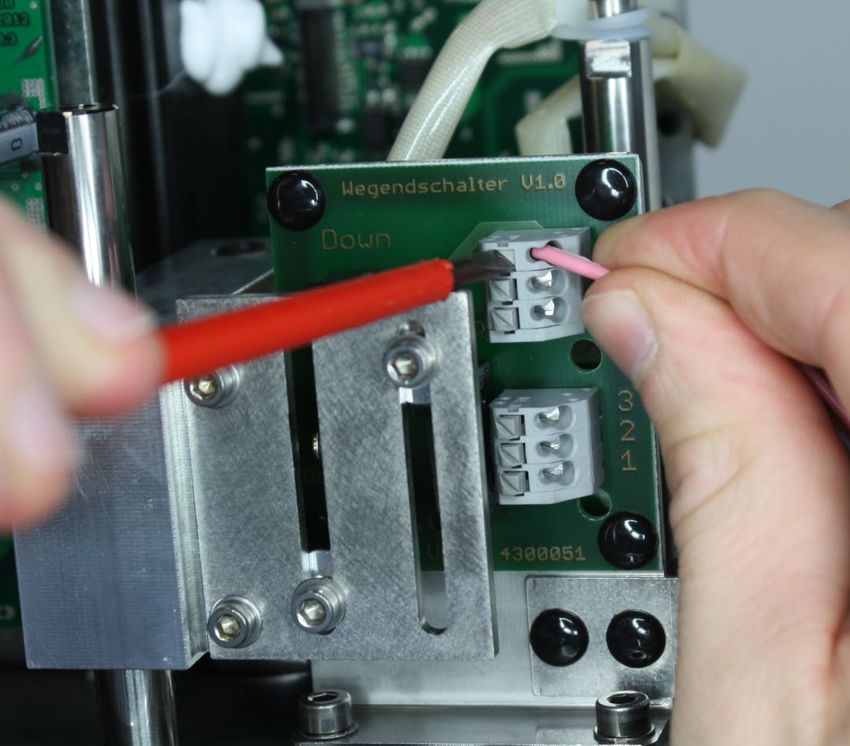
Inhalt/Content/Sommaire

1          Betriebsanleitung (deutsch) ...................................................... 3
    1.1   Technische Daten                                                                  3
    1.2   Einbau                                                                            4
    1.3   Elektrischer Anschluss                                                            5
    1.4   Adaption des Antriebs                                                             12
    1.5   Hand-Betrieb                                                                      13
    1.6   Störmeldeausgang                                                                  15
    1.7   Nachrüsten der Endlagenschalter                                                   19
    1.8   Einstellen der Endlagenschalter                                                   22
    1.9   Kommunikationssoftware                                                            23
2                 Operating Instructions (English) ..................................... 26
    2.1   Technical data                                                                    26
    2.2   Installation                                                                      27
    2.3   Electrical connection                                                             28
    2.4   Adaptation of the actuator                                                        35
    2.5   Manual operation                                                                  36
    2.6   Fault alarm output                                                                38
    2.7   Setting the limit switches                                                        40
    2.8   Communications software                                                           46
3           Instructions de service (français) ........................................... 50
    3.1   Caractéristiques techniques                                                       50
    3.2   pose                                                                              51
    3.3   Raccordement électrique                                                           52
    3.4   Adaptation de l’actionneur                                                        59
    3.5   Mode manuel                                                                       60
    3.6   Sortie de signal d’erreur                                                         62
    3.7   Réglage des interrupteurs de fin de course                                        69
    3.8   Logiciel de communication                                                         70

                                                  -2–
1             Betriebsanleitung (deutsch)

       Technische Daten

Technische Daten des Antriebs mit Positionsregelung

Stellkraft                                2,0 kN / 5,0 kN
Netzanschlüsse                            24 V AC/DC
                                          100 - 240 V 50/60Hz
zul. Umgebungstemperatur                  Standard:                  -10°C bis +60°C
                                          Tieftemperaturversion:     -40°C bis +60°C
zul. Lagertemperatur                      Standard:                  -30°C bis +80°C (+60°C mit Nullspannungsrückstellung)
                                          Tieftemperaturversion:     -40°C bis +80°C (+60°C mit Nullspannungsrückstellung)
Einbaulage                                beliebig, jedoch Motor nicht nach unten
Schutzart (EN 60529)                      IP 67
max. Leistungsaufnahme bei 24V            40 Watt
AC/DC-Berieb
Nennleistung bei Netzbetrieb              Netzanschluss 230V:          P=40W S=67,8VA I=295mA                       cosφ=0.59
                                          Netzanschluss 115V:          P=40W S=58,8VA I=511mA                       cosφ=0.68
Totband                                   ±0,2% bei min. 6mm Hub
Wiederholgenauigkeit                      ±0,1% bei min. 6mm Hub
Stellgeschwindigkeit                      2,0 kN-Version:              0,75 s/mm bis 250 s/mm (Standard 1,5 s/mm)
                                          5,0 kN-Version:              2 s/mm bis 250 s/mm (Standard 4 s/mm)
Stellgeschwindigkeit der                  2,0 kN-Version:              0,75 s/mm bis 4 s/mm
Nullspannungsrückstellung                 5,0 kN-Version:              2 s/mm bis 4 s/mm
Sollwertbereich                           einstellbar 0(4) - 20 mA, 0(2) - 10 V
                                          optional binäre Ansteuerung (24V DC)
Rückmeldung                               einstellbar 0(4) - 20 mA, 0(2) - 10 V
Zyklen (Nullspannungsrückstellung)        500000
Lebensdauer (Nullspannungsrückstellung)   10 Jahre
Einschaltdauer                            100%

Sicherheitsfunktionen                     Überwachung von Zugkraft, Sollwert, Motortemperatur, Temperatur der Elektronik usw.

Diagnosefunktionen                        Speicherung von Motor- und Gesamtbetriebsdauer, Temperatur- und Wegeklassen usw.
Ventiladaption                            Automatischer Hubabgleich des Antriebs
zusätzliche Eingange                      1 Binäreingang (programmierbar)
zusätzliche Ausgänge                      2 Alarmausgänge

Weitere technische Daten entnehmen Sie bitte den Datenblättern.

                                                             -3–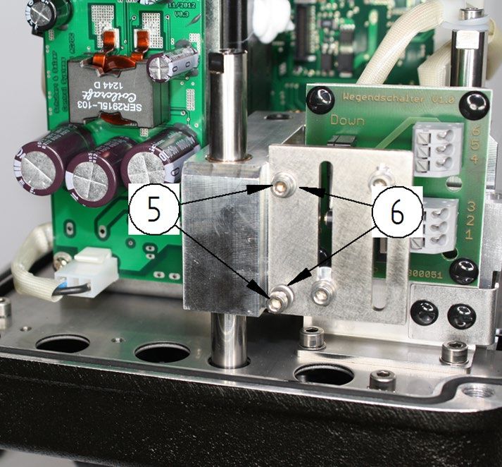
Einbau
Von dem Antrieb sind alle Verpackungsmaterialien zu entfernen.

Die Einbaulage des Motors ist beliebig, mit Ausnahme der Stellung „Haube nach unten“

Die Funktion des kompletten eingebauten Motors ist vor der Inbetriebnahme der Anlage zu
überprüfen.

                                            -4–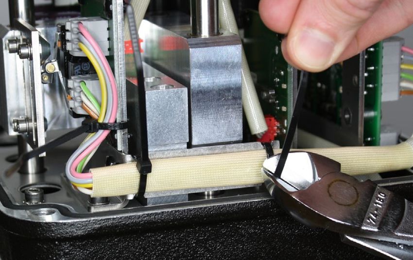
Elektrischer Anschluss
Der elektrische Anschluss erfolgt am integrierten Klemmkasten des Antriebs.

Hier finden Sie auch alle Taster für die Vor-Ort Bedienung und ein LCD Display.

Die Antriebshaube muss nicht abmontiert werden !

Der minimale Aderquerschnitt beträgt für alle Versorgungs- und Signalleitungen 0,5 mm².
Die Klemmen sind für einen maximalen Aderquerschnitt von 2,5 mm² ausgelegt.
Für lange Versorgungsleitungen (>5m) muss ein größerer Aderquerschnitt verwendet werden
damit der Spannungsabfall nicht unter den spezifizierten Bereich von 24V (+)- 10% fällt.

Für sicheren Kontakt Aderendhülsen verwenden.

                 Der elektrische Anschluss darf nur durch qualifiziertes Personal erfolgen.
                 Beachten Sie unbedingt bei Montage, Inbetriebnahme und Betrieb der
                 Geräte die entsprechenden nationalen Sicherheitsvorschriften (z. B. VDE
                 0100).
                 Alle Arbeiten dürfen nur im spannungslosen Zustand erfolgen.
                 Bei Nichtbeachten der entsprechenden Vorschriften können schwere
                 Körperverletzungen und/oder Sachschäden auftreten.

                                             -5–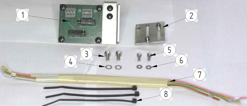
1.3.1 Klemmenbelegung für Antriebe mit Positionselektronik

Die Belegung der Klemmen ist auf einem Schaltplan auf der Rückseite des Deckels für den
Klemmenkasten angegeben. Die Anschlussklemmen sowie die Erdungsklemme sind
entsprechend gekennzeichnet.

       Klemme    Kurzbezeichnung   Funktion
           1     U in              Stellsignaleingang 0(2)-10 V
           2     I in              Stellsignaleingang 0(4)-20mA
           3     0                 Stellsignal (-)
           4     0                 Stellungsrückmeldung (-)
           5     I out             Stellungsrückmeldung 0(4)-20mA
           6     U out             Stellungsrückmeldung 0(2)-10 V
           7     Alarm 1           Alarmausgang 1
           8     Alarm 2           Alarmausgang 2
           9     0                 Alarmausgang COM
          10     Bin in            Binäreingang (+)
          11     Bin 0             Binäreingang (-)
          12     L+                Spannungsversorgung L bei AC, (+) bei DC
          13     N-                Spannungsversorgung N bei AC, (-) bei DC
          14     SW1 NC            Endschalter 1 Öffner
          15     SW1 0             Endschalterb 1 COM
          16     SW1 NO            Endschalter 1 Schließer
          17     SW2 NC            Endschalter 2 Öffner
          18     SW2 0             Endschalterb 2 COM
          19     SW2 NO            Endschalter 2 Schließer
          20     CL                Binäransteuerung Schließrichtung (+)
          21     0                 Binäransteuerung (-)
          22     OP                Binäransteuerung Öffnungsrichtung (+)

                                          -6–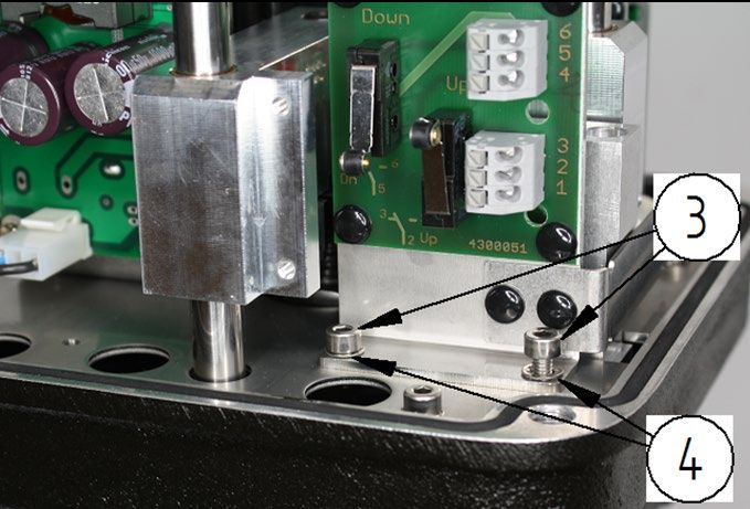
1.3.2 Versorgungsspannung

Die Spannungswerte für die Versorgungsspannung sind dem Typenschild des Antriebs zu
entnehmen.

                Anschluss DC                                    Anschluss AC

                      12 13                                              12 13

             DC (+)            DC (-)                        AC (L)              AC (N)

1.3.3 Stellsignal (Sollwert)

Der Antrieb kann sowohl mit einem Stellsignal als Stromsignal (0/4-20mA) als auch mit einem
Spannungssignal (0/2-10V) betrieben werden.

            Stellsignal (0/4-20mA)                           Stellsignal (0/2-10V)

                 1    2   3                                          1    2   3

                              Signal (-)                    Signal                Signal (-)
                   Signal                                  0/2-10V
                 0/4-20mA

           Standardsignal: 4-20mA                          Stamndardsignal: 2-10V
      min. Eingangswiderstand 100 Ohm                 min. Eingangswiderstand 60 kOhm

                 Der Signalbereich kann mit der Kommunikationssoftware „DeviceConfig“
                 verändert werden.

                                            -7–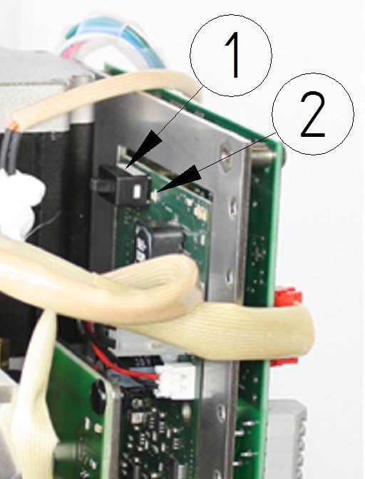
1.3.4 Stellungsrückmeldung (Istwert)

Der Antrieb kann die aktuelle Position des Antriebs sowohl mit einem Stromsignal (0/4-20mA)
als auch mit einem Spannungssignal (0/2-10V) zurückmelden.

      Stellungsrückmeldung (0/4-20mA)                   Stellungsrückmeldung (0/2-10V)

                          4   5   6                                     4   5   6

             Signal (-)                                                              Signal
                                                           Signal (-)
                        Signal                                                      0/2-10V
                      0/4-20mA

          Standardsignal: 4-20mA                             Standardsignal: 2-10V
        max. Lastwiderstand 500Ohm                        min. Lastwiderstand: 5kOhm
              (max. Bürde 10V)

                  Der Signalbereich kann mit der Kommunikationssoftware „DeviceConfig“
                  verändert werden.

1.3.5 Binäreingang

                  Der Binäreingang ist für Sonderfunktionen vorbehalten und in der
                  Standardausführung ohne Funktion.

                                                                 Signal: 24V DC

                                                        (max. Signalbereich 12-30V DC)

                                             -8–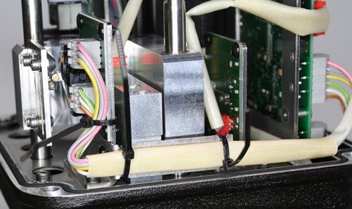
1.3.6 Binäre Ansteuerung (3-Punkt Schritt Regelung)

Der Antrieb kann so konfiguriert werden, dass er mit einem binären Signal (24V DC)
angesteuert werden kann.
Der Antrieb verhält sich dann wie ein Stellantrieb ohne Positionselektronik.

Die zusätzlichen Funktionen der Positionselektronik wie Stellungsrückmeldung, Alarmausgang,
Wartungsdaten, Selbstabgleich usw. können aber auch bei dieser Ansteuerung genutzt werden.

      Ventilspindel fährt aus Antrieb aus:                       Ventil HALT

                                                                 STOP

                 20 21 22                                        20 21 22

    BIN (+)                        BIN (+)           BIN (+)                     BIN (+)

                   BIN (-)                                         BIN (-)

     Ventilspindel fährt in den Antrieb ein:

                                                               Signal: 24V DC
                  20 21 22                              (max. Signalbereich 12-30V DC)

     BIN (+)                       BIN (+)

                    BIN (-)

                 Die Umstellung von analoger Ansteuerung auf Binäre Ansteuerung kann nur
                 mit der Konfigurationssoftware durchgeführt werden.

                                               -9–
1.3.7 Endlagenschalter (Optional)

Der Antrieb kann mit zwei wegabhängigen Endlagenschaltern ausgerüstet werden.

Beide Endlagenschalter sind als Wechsler ausgeführt.

Die Anschlussklemmen für die Endlagenschalter sind in den Klemmenraum geführt.

Die Klemmen 14-16 sind mit dem unteren Endlagenschalter verbunden, die Klemmen 17-19 mit
dem oberen Endlagenschalter.

                                       Anschluss DC

                                   14 15 16 17 18 19

                                max. 250V AC/DC, max.1A

                Hier angeschlossene Fremdspannungen sind zu kennzeichnen, da diese
                auch bei abgeschalteter Versorgungsspannung anliegen können.

                                           - 10 –
1.3.8 Externes Stromversorgungsmodul (3-Phasen-Wechselstrom)
Für den Betrieb des Motorantriebes mit 3-Phasen-Wechselstrom (2x/3x 400…500V AC)
empfehlen wir die Verwendung eines Stromversorgungsmoduls.
Z.B. Typ TRIO-PS/3AC/24DC/5 von PHOENIX CONTACT.
Das Stromversorgungsmodul wird auf eine Hutschiene im Schaltschrank montiert. Die
Versorgung des el. Antriebes erfolgt dann mit 24V DC. Die Motorspannung ist
dementsprechend zu wählen.
Anschlussschema:
- 11 –Adaption des Antriebs
Alle Antriebe sind werkseitig auf die dazugehörige Armatur eingestellt und
geprüft.
Eine Adaption oder Justage ist nicht erforderlich.
Nach Reparatur oder bei Austausch des Antriebs muss jedoch die
Einstellung des Antriebs überprüft und ggf. eine neue Adaption
vorgenommen werden.
Bei der automatischen Adaption wird der eingestellte Hub der Armatur durchfahren.
Dabei werden die ventilspezifischen Parameter gemessen und dauerhaft im Antrieb
gespeichert.
Am Ende der Adaption erfolgt eine Normierung der Soll- und Istwert-Signale auf den
Hubbereich der Armatur
S1 S2
Auto %
• Die beiden Tasten S1 und S2 gleichzeitig für ca. 3
03 4 Sekunden drücken.
S3
LCD
S1 S2 • Das Antrieb wechselt vom Automatikbetrieb in den
Adaptionsbetrieb.
ADA
S3
• Dies wird im Display angezeigt.
LCD
• Der Antrieb durchfährt 1-mal den gesamten Hubbereich
des Ventils.
S1 S2 • Nach Ende der Adaption.
• Der Antrieb wechselt selbst wieder in den
Auto % Automatikbetrieb.
03 4 • Der Ventilhub in % wird angezeigt.
S3
LCD
- 12 –Hand-Betrieb
1.5.1 Verfahren mit Handrad
Der Antrieb kann mit dem seitlichen Sterngriff von Hand verstellt werden.
Antriebe mit Positionselektronik können nur mit dem Handrad verfahren
werden, wenn sie nicht unter Spannung stehen und keine Notstellfunktion
integriert ist.
Bei Antrieben mit Notstellfunktion kann diese mit dem Serviceschalter
deaktiviert werden (siehe Fehler! Verweisquelle konnte nicht gefunden
werden.)
Die Positionselektronik würde den Antrieb immer wieder in seine
Ausgangsstellung zurückfahren.
Ein Verfahren ist dann nur im „MAUELL“-Modus möglich!
2kN-Antrieb 5kN-Antrieb
Einfahren der Spindel in den
Antrieb:
• 2kN-Antrieb:
Drehen der Handbetätigung
im Uhrzeigersinn
• 5kN-Antrieb:
Drehen der Handbetätigung
gegen den Uhrzeigersinn
Ausfahren der Spindel aus dem
Antrieb:
• 2kN-Antrieb:
Drehen der Handbetätigung
gegen den Uhrzeigersinn
• 5kN-Antrieb:
Drehen der Handbetätigung
im Uhrzeigersinn
- 13 –1.5.2 Verfahren im „MANUELL“-Modus
S1 S2
• Entweder die Taste S1 oder die Tasten S2 für
Auto % ca. 3 Sekunden drücken.
03 4
S3
LCD
• Der Antrieb wechselt in den „MANUELL“-Modus
• Anzeige mit Symbol im Display
• Bei Drücken der Taste S1 fährt die Spindel in
den Antrieb ein.
• Die aktuelle Antriebsposition wird angezeigt.
• Bei Drücken der Taste S1 fährt die Spindel aus
dem Antrieb aus.
• Die aktuelle Antriebsposition wird angezeigt.
S1 S2
• Durch gleichzeitiges Drücken beider Taster
Auto %
wechselt der Antrieb wider in den Automatik-
03 4 Betrieb.
S3
LCD
- 14 –Störmeldeausgang
Bei Auftreten von Störungen werden diese mit einem Code (E01, E02 usw.) auf dem Display
angezeigt und werden an den Sammelstörmeldeausgängen ausgegeben.
Die Anzeige des Fehlercodes wechselt sich sekündlich mit der Anzeige der aktuellen
Ventilposition im Display ab.
Mit DeviceConfig kann frei eingestellt werden, welcher Fehler auf welchem Störmeldeausgang
ausgegeben wird.
Der Störmeldeausgang kann als „Öffner“ oder „Schließer“ ausgeführt werden.
Wenn der Motorantrieb ausgeschaltet ist, sind beide Störmeldeausgänge „offen“ unabhängig
von der Einstellung in DeviceConfig.
Standardmäßig wird nur der Regelfehler auf Klemme 7 („Alarm 1“) ausgegeben und beide
Störmeldeausgänge sind als „Schließer“ konfiguriert.
• Die Störmeldeausgänge schalten eine
angeschlossene Spannung (max. 24V
AC/DC).
• Die Polarität ist beliebig.
7 8 9 • Er ist mit max. 70 mA belastbar.
(so dass auch z.B. Relais direkt
betrieben werden können)
Alarm 1 Alarm COM • Bei induktiven Lasten ist eine
Freilaufdiode vorzusehen.
Alarm 2
Die Bedeutung der Fehlercodes kann der nachfolgenden Tabelle entnommen werden.
Anzeige Fehler Ursache/Behebung
E01 Antrieb ist nicht abgeglichen Abgleich durchführen
Es liegt entweder kein
Stellsignal an, oder das
E02 Sollwertfehler
Stellsignal liegt außerhalb des
gültigen Bereiches
Der Antrieb erreicht nicht
E03 Regelfehler
seine Sollposition
- 15 –E06 EEPROM Motorantrieb neu starten
Die Versorgungsspannung an
E20 Netzausfall den Klemmen 12, 13 ist
ausgefallen
Fail Safe - Funktionsfehler Die Fail Safe Funktion steht
E21 nicht zur Verfügung.
Ursachen:
• Serviceschalter ist in
„OFF“ Stellung
• Selbsttest der
Elektronik wurde nicht
bestanden
• Lebensende der
Kondensatoren ist
erreicht
Fail Safe - Ladevorgang Es ist noch nicht genügend
E22 Energie im Kondensatorpaket
gespeichert um den Antrieb
sicher in die
Sicherheitsstellung zu fahren.
Das Kondensatorpaket wird
aufgeladen.
- 16 –Sonderfunktionen
Die Sonderfunktionen ermöglichen es auf besondere externe Ereignisse eine voreingestellte
Aktion auszuführen und das analoge Sollwertsignal zu ignorieren.
Treten gleichzeitig mehrere Ereignisse auf, für die eine Sonderfunktion hinterlegt ist, werden sie
mit folgender Priorität ausgeführt:
(1 = höchste Priorität)
1. Sonderfunktion bei Netzausfall
2. Sonderfunktion bei Fail Safe – Funktionsfehler
3. Sonderfunktion bei Fail Safe – Ladevorgang
4. Sonderfunktion bei Binäreingang betätigt
5. Sonderfunktion bei Binäreingang offen
6. Sonderfunktion bei Sollwertfehler
7. Verwendung des analogen Sollwertsignals
Bsp:
Liegt gleichzeitig ein Sollwertfehler und ein Netzausfall vor, wird die Sonderfunktion des
Netzausfalls ausgeführt. Die Sonderaktion bei Sollwertfehler und der analoge Sollwert wird
ignoriert.
1.7.1 Einstellung der Sonderfunktionen
Mit der Konfigurierungssoftware DeviceConfig können Sonderfunktionen für den Binäreingang,
Sollwertfehler, Netzausfall, Fail Safe – Funktionsfehler und Fail Safe – Ladevorgang festgelegt
werden.
• Inaktiv:
Obwohl ein externes Ereignis vorliegt wird keine Sonderfunktion ausgeführt.
• Stopp:
Der Motorantrieb hält seine momentane Position, auch wenn sich das analoge
Sollwertsignal ändert.
• Sollwertvorgabe:
Hier kann ein beliebiger Sollwert vorgegeben werden, der anstatt des analogen Sollwerts
angefahren wird.
(Beispiel: Eine eingestellte Sollwertvorgabe von 0% würde bei Standardeinstellung
einem externen Sollwert von 4 mA / 2V entsprechen und der Motorantrieb schließt das
Ventil.)
• Spindel (in Antrieb) einfahren bis Endanschlag:
Die Spindel wird komplett eingefahren, bis die Lastendschalter ansprechen. Dadurch
wirkt die volle Kraft von 2kN auch wenn der Motorantrieb abschaltet.
(Bei Standardeinstellung: Motorantrieb öffnet das Ventil)
• Spindel (aus Antrieb) ausfahren bis Endanschlag:
Die Spindel wird komplett ausgefahren, bis die Lastendschalter ansprechen. Dadurch
wirkt die volle Kraft von 2kN auch wenn der Motorantrieb abschaltet.
(Bei Standardeinstellung: Motorantrieb schließt das Ventil)
- 17 –1.7.2 Aktion bei Sollwertfehler („Fail in Pos“)
Eine Sonderfunktion des Sollwertfehlers kann nur für den Stellsignalbereich von 4-20mA (2-
10V) festgelegt werden.
Standardmäßig ist eine Sollwertvorgabe von 0% eingestellt. Bei Standardeinstellung hat dies
ein Schließen des Ventils zu Folge.
Während die Sonderfunktion des Sollwertfehlers ausgeführt wird ist das Ausrufezeichen im
Display aktiv.
1.7.3 Fail Safe Funktion (optional)
Die Sonderfunktionen der Fail Safe Funktion wirken nur, wenn die Hardware der Fail Safe
Funktion vorhanden ist und die Verwendung im DeviceConfig eingestellt ist. (siehe 0 Fail Safe
Funktion)
Alle Sonderfunktionen sind standardmäßig so eingestellt, dass der Motorantrieb seine
Sicherheitsstellung nur verlässt, wenn er bei Netzausfall seine Sicherheitsstellung sicher wieder
erreichen kann.
• E 20 -Netzausfall:
Die Sonderfunktion Netzausfall ist aktiv, wenn die Versorgungspannung an den
Klemmen 12, 13 ausgefallen ist.
Standardmäßig ist eine Sollwertvorgabe von 0% eingestellt. Bei Standardeinstellung hat
dies ein Schließen des Ventils zu Folge.
Während die Sonderfunktion „Netzausfall“ ausgeführt wird ist das Ausrufezeichen im
Display aktiv.
Während des Netzausfalls reagiert die Baugruppe nicht auf Tastendrücke und es kann
keine Kommunikation mit DeviceConfig aufgebaut werden. Auch eine manuelle
Verstellung mit dem Handrad ist nicht möglich.
• E 21 - Fail Safe - Funktionsfehler:
Die Sonderfunktion „Fail Safe – Funktionsfehler“ ist aktiv, wenn die Fail Safe Funktion
nicht ordnungsgemäß arbeiten kann. Mögliche Ursachen sind:
o Serviceschalter ist in „OFF“ Stellung
o Selbsttest der Elektronik wurde nicht bestanden
o Lebensende der Kondensatoren ist erreicht
Standardmäßig ist eine Sollwertvorgabe von 0% eingestellt. Bei Standardeinstellung hat
dies ein Schließen des Ventils zu Folge.
Während die Sonderfunktion „Fail Safe - Funktionsfehler“ ausgeführt wird ist das
Ausrufezeichen im Display aktiv.
• E 22 - Fail Safe - Ladevorgang:
Die Sonderfunktion „Fail Safe – Ladevorgang“ ist aktiv, wenn die Kondensatoren noch
nicht genug Energie gespeichert haben um das Ventil sicher in die Sicherheitsstellung zu
fahren.
Standardmäßig ist eine Sollwertvorgabe von 0% eingestellt. Bei Standardeinstellung hat
dies ein Schließen des Ventils zu Folge.
Während die Sonderfunktion „Fail Safe - Ladevorgang“ ausgeführt wird ist das
Ausrufezeichen im Display aktiv.
- 18 –Nachrüsten der Endlagenschalter
Nachrüstsatz (4 099 014):
(1) 1 x Platine mit Endschaltern
(2) 1 x Blech mit Schaltnocken
(3) 2 x Zylinderschraube M4x8
(4) 2 x Zahnscheibe
(5) 2 x Zylinderschraube M3x8
(6) 2 x Scheibe
(7) 1 x Kabelbaum
(8) 3 x Kabelbinder
• Platine mit Endschaltern (1)
mit 2 x Zylinderschraube (3)
und 2 x Zahnscheiben (4) auf
Grundplatte des Antriebes
schrauben.
• Blech mit Schaltnocken (2) mit
2 x Zylinderschraube (5) und
2 x Scheibe (6) auf
Verdrehsicherungsstrebe
schrauben.
- 19 –• Kabelbaum (7) an Platine mit
Endschalter anschließen
• Öffnen der Klemmen durch
einpressen des Schalters mit
Schraubendreher
• Kabelbaum (7) an
Hauptplatine anschließen
rosa
6
Endschalter
grau 6
(down)
5 5
gelb
4
Hauptplatine
Klemmleiste
4
3 grün 3
Endschalter
2 braun 2
(up)
1 weiß 1
- 20 –• Sichern des Kabelbaums (7)
mit 3 x Kabelbinder (8)
• Einfädeln durch:
2x Nut in Lasche der Platine
mit Endschaltern (1)
1x durch unteres Loch in
Platine mit Endschaltern (1)
• Abtrennen der losen
Kabelbinderenden
- 21 –Einstellen der Endlagenschalter
Die Endlagenschalter sind Zubehör und daher in der „Standardausführung“
nicht enthalten!
Einstellen des unteren Endschalters
• Ventil in die untere Endlage fahren.
• Schraube der Schaltnocke(1) für den
unteren Endschalter lösen
(Innensechskant 3mm).
• Schaltnocke von oben kommend so weit
nach unten schieben bis der Endschalter
betätigt wird.
• Schaltpunkt an den Klemmen 14-16
kontrollieren.
• Schraube der Schaltnocke festziehen.
Einstellen des oberen Endschalters
• Ventil in die obere Endlage fahren.
• Schraube der Schaltnocke(2) für den
oberen Endschalter lösen
(Innensechskant 3mm).
• Schaltnocke von unten kommend so weit
nach oben schieben bis der Endschalter
betätigt wird.
• Schaltpunkt an den Klemmen 17-19
kontrollieren.
• Schraube der Schaltnocke festziehen.
- 22 –Kommunikationssoftware
(Optional nur für Antriebe mit Positionselektronik)
Die Einstellung der Funktionsparameter des Antriebs kann über eine PC-Schnittstelle und die
entsprechende Konfigurierungssoftware „DeviceConfig“ ab Version 7.03.00 erfolgen.
Sie wird benötigt, wenn die werksseitigen Einstellungen des Antriebs verändert werden sollen
(z.B. Einrichtung von Split-Range-Betrieb, Signalbereich, Realisierung spezieller Kennlinien).
Für die Inbetriebnahme sowie den Betrieb des Antriebs und auch dessen Justierung nach
einem evtl. Austausch wird sie nicht benötigt, wenn nicht spezielle lokale Einstellungen
gespeichert waren.
LED1 LED2
1 2 3 4 5 6 7 8 9 10 11 S1 S2
DISPLAY
12 13 S3
LCD
PC-COM
14 15 16 17 18 19 20 21 22 LED3
Der Anschluss an einen PC erfolgt über einem speziellen Adapter am Anschluss „PC-COM“ im
Klemmraum des Antriebs.
Software und Adapter können bei Schubert & Salzer Control Systems GmbH bezogen werden.
Die neueste Version von „DeviceConfig“ kann kostenlos auf der Internetseite von Schubert &
Salzer heruntergeladen werden.
Das Standard-Anwenderpasswort ist: „0000“
- 23 –Fail Safe Funktion
(Optional)
Die optionale Fail Safe Funktion besteht aus einem Kondensatorpaket, welches sich in einem
Zusatzgehäuse auf der Rückseite des Motorantriebs befindet, und einer Zusatzplatine.
Mit der Fail Safe Funktion kann sichergestellt werden, dass der Motorantrieb im Falle eines
Stromausfalls in eine frei einstellbare Sicherheitsstellung fährt. (siehe 0 Sonderfunktionen)
Die Fail Safe Funktion ist nicht nachrüstbar!
Die Fail Safe Funktion ist mit DeviceConfig ausschaltbar.
Im Auslieferungszustand ist die Fail Safe Funktion immer aktiv.
1.11.1 Sicherheitsfunktionen
Um die Funktion im Falle eines Netzausfalls zu gewährleisten sind mehrere
Sicherheitsfunktionen integriert.
Standardmäßig schließt der Motor das Ventil, wenn eine der Sicherheitsfunktionen einen Fehler
diagnostiziert.
Der Ladezustand der Kondensatoren wird fortlaufend überwacht. Reicht die Energie im
Kondensatorpaket nicht aus um den Motorantrieb in die Sicherheitsstellung zu fahren wird dies
mit der Anzeige „E22 – Fail Safe Ladevorgang“ signalisiert.
Die Funktionsbereitschaft der Fail Safe Zusatzplatine wird fortlaufend überwacht. Wenn keine
Verbindung zu der Platine aufgebaut werden kann wird dies mit der Anzeige „E-21 – Fail Safe
Funktionsfehler“ signalisiert.
Die Verbindung zu den Kondensatoren wird zyklisch getestet. Dadurch kann ein Kabelbruch
oder eine defekte Sicherung etc. erkannt werden. Sollte die Verbindung einen Defekt aufweisen
wird dies mit der Anzeige „E-21 – Fail Safe Funktionsfehler“ signalisiert.
Am Ende des Ladevorgangs wird automatisch eine erweiterte Diagnose gestartet. Dabei wird
der Antrieb kurzzeitig aus dem Kondensatorpaket versorgt. Während dieses Tests erscheint
„tst“ im Display. Wenn dieser Test fehlschlägt wird dies mit der Anzeige „E-21 – Fail Safe
Funktionsfehler“ signalisiert.
Sollte während eines dieser Tests die Versorgungspannung ausfallen
(„Netzausfall“) erreicht der Motorantrieb trotzdem seine Sicherheitsstellung.
Nach Anschluss der Spannungversorgung beträgt die Ladezeit der
Kondensatoren bis zu 3 Minuten. In der Standardeinstellung verbleibt der
Antrieb in der Sicherheitsstellung. Diese Einstellung kann mit DeviceConfig
geändert werden.
- 24 –1.11.2 Kapazitätsmessung
Da die Kondensatoren einer gewissen Alterung unterliegen muss in
regelmäßigen Abständen die verbliebene Kapazität des Kondensatorpakets
ermittelt werden!
Die Kapazitätsmessung kann mit DeviceConfig gestartet werden. Der benötigte Button befindet
sich im Fenster „Einstellungen“ unter der Registerkarte „Fail Safe Funktion“.
Während der Kapazitätsmessung wird das Kondensatorpaket gezielt entladen und wieder
vollständig geladen. Dies benötigt etwa 15 Minuten.
Nach der Messung wertet der Motorantrieb das Ergebnis aus. Reicht die Restkapazität nicht
aus um den Motorantrieb sicher in die Sicherheitsstellung zu bewegen wird der Fehler „E21 –
Fail Safe Funktionsfehler“ angezeigt.
Der Motorantrieb ist während der Kapazitätsmessung nicht betriebsbereit.
Die aktuelle Ventilposition wird während der gesamten Messdauer gehalten.
Die Kapazitätsmessung kann nicht unterbrochen oder angehalten werden!
Entsorgung
Das Gerät und die Verpackung müssen entsprechend den einschlägigen Gesetzen und
Vorschriften im jeweiligen Land entsorgt werden.
- 25 –2 Operating Instructions (English)
Technical data
Technical data for the actuator with position control
Driving force 2,0 kN / 5,0 kN
Power connections 24 V AC/DC
100 - 240 V 50/60Hz
Ambient temperature Standard: -10°C up to +60°C
Low temperature version: -40°C up to +60°C
Storage Temperature Standard: -30°C up to +80°C (+60°C with Fail-Safe protection)
Low temperature version: -40°C up to +80°C (+60°C with Fail-Safe protection)
Mounting position choice horizontal or vertical actuator only
Protection class (EN 60529) IP 67
Max. power consumption at 40 Watt
24V AC/DC-operation
Nominal power consumption Mains voltage 230V: P=40W S=67,8VA I=295mA cosφ=0.59
during Mains voltage 115V: P=40W S=58,8VA I=511mA cosφ=0.68
mains operation
Dead band ±0,2% at min. 6mm stroke
Repeat accuracy ±0,1% at min. 6mm stroke
Stroking speed 2,0 kN-version: 0,75 s/mm up to 250 s/mm (standard 1,5 s/mm)
5,0 kN-version: 2 s/mm up to 250 s/mm (standard 4 s/mm)
Stroking speed of the Fail- 2,0 kN-version: 0,75 s/mm up to 4 s/mm
Safe protection 5,0 kN-version: 2 s/mm up to 4 s/mm
Set point range adjustable 0(4) - 20 mA, 0(2) - 10 V
optional binary input signal (24V DC)
Feed back adjustable 0(4) - 20 mA, 0(2) - 10 V
cycles (Fail-Safe) 500000
life-time (Fail-Safe) 10 years
duty cycle 100%
Self Monitoring monitoring of the driving power, set point, actuator temperature,
temperatrure of the electronic etc.
Diagnostic function storage of motor and total service life, temperature- and way classes
Valve adaptation automatic stroke adjustment to suit valve limits
additional inputs binary input
additonal outputs 2 alarm outputs
Further technical data can be found in the data sheets.
- 26 –Installation
Remove all packaging materials from the valve.
Before installation, check the pipework for contamination and impurities and clean if necessary.
The mounting position of the motor is optional except for the position where the motor would
hang downwards.
Before starting up the plant, check the operation of the complete installed valve.
- 27 –Electrical connection
The electrical connection is made at the terminal box integral with the actuator.
In it, you will find all buttons needed for local operation as well as an LCD display.
The actuator cap must not be removed !
The minimum core cross section for all supply and signal conductors is 0.5 mm² (AWG 21).
The terminals are designed for a maximum core cross section of 2.5 mm² (AWG 14).
For long supply lines (>5m), a larger core cross section must be used so that the voltage drop
does not fall below the specified range of 24V ± 10%.
Wire-end sleeves are to be used to ensure a safe contact.
The electrical installation must only be carried out by qualified personnel.
Please note the applicable national safety regulations for installation,
start-up and operation of the device.
All work has to be carried out isolated from the power supply. Disregarding
the relevant regulations may cause serious physical injuries and/or property
damage.
- 28 –2.3.1 Terminal layout for actuators with position electronics
The layout of the terminals is provided on a circuit diagram on the reverse side of the cover for
the terminal box. The connection terminals and ground terminal are marked accordingly.
Terminal Abbreviation Function
1 U in Set point signal input 0(2)-10 V
2 I in Set point signal input 0(4)-20mA
3 0 Set point signal (-)
4 0 Position feedback (-)
5 I out Position feedback 0(4)-20mA
6 U out Position feedback 0(2)-10 V
7 Alarm 1 Alarm output 1
8 Alarm 2 Alarm output 2
9 0 Alarm output COM
10 Bin in Binary input (+)
11 Bin 0 Binary input (-)
12 L+ Power supply L with AC, (+) with DC
13 N- Power supply N with AC, (-) with DC
14 SW1 NC Limit switch 1 opener
15 SW1 0 Limit switch b 1 COM
16 SW1 NO Limit switch 1 closer
17 SW2 NC Limit switch 2 opener
18 SW2 0 Limit switch b 2 COM
19 SW2 NO Limit switch 2 closer
20 CL Binary actuation of closing direction (+)
21 0 Binary actuation (-)
22 OP Binary actuation of opening direction (+)
- 29 –2.3.2 Supply voltage
The voltage values for the supply voltage can be read off the type plate of the actuator.
DC connection AC connection
12 13 12 13
DC (+) DC (-) AC (L) AC (N)
2.3.3 Control signal (set point)
The actuator can be operated by a set point represented both by a current signal (0/4-20mA) as
well as by a voltage signal (0/2-10V).
Set point (0/4-20mA) Set point (0/2-10V)
1 2 3 1 2 3
Signal (-) Signal Signal (-)
Signal 0/2-10V
0/4-20mA
Standard signal: 4-20mA Standard signal: 2-10V
min. input resistance 100 Ohm min. input resistance 60 kOhm
The signal range can be changed with the communications software
“DeviceConfig”.
- 30 –2.3.4 Position feedback (actual value)
The actuator can feed back its actual position both by a current signal (0/4-20mA) as well as by
a voltage signal (0/2-10V).
Position feedback (0/4-20mA) Position feedback (0/2-10V)
4 5 6 4 5 6
Signal (-) Signal
Signal (-)
Signal 0/2-10V
0/4-20mA
Standard signal: 4-20mA Standard signal: 2-10V
max. load resistance: 500Ohm min. load resistance: 5kOhm
(max. load 10V)
The signal range can be changed with the communications software
“DeviceConfig”.
2.3.5 Binary input
Binary input is reserved for special functions and does not operate in the
standard version.
Signal: 24V DC
(max. signal range 12-30V DC)
The binary input overwrites the set point signal present and executes the stored special
function.
- 31 –A special function can be predefined both for the “actuated” as well as for the “open” state. (see
0 Special functions)
While a special function of the binary input is being executed, the display of the current valve
position alternates with “bin” shown on the display.
2.3.6 Binary activation (3-point step adjustment)
The actuator can be configured such that it can be activated with a binary signal (24V DC).
The actuator then behaves like an actuator without position electronics.
The additional functions of the position electronics such as position feedback, alarm output,
maintenance data, self-alignment, etc., can still be used, however, with this activation.
Valve stem extends out from actuator: Valve STOPS
STOP
20 21 22 20 21 22
BIN (+) BIN (+) BIN (+) BIN (+)
BIN (-) BIN (-)
Valve stem retracts into actuator:
Signal: 24V DC
20 21 22 (max. signal range 12-30V DC)
BIN (+) BIN (+)
BIN (-)
The changeover from analogue to binary activation can only be performed
using the configuration software.
- 32 –2.3.7 Limit switch (optional)
The actuator can be fitted with two stroke-dependent limit switches.
Both limit switches are designed as two-way contacts.
The connection terminals for the limit switches are routed into the terminal compartment.
Terminals 14-16 are connected to the lower limit switch and terminals 17-19 to the upper limit
switch.
DC connection
14 15 16 17 18 19
max. 250V AC/DC, max.1A
Extraneous voltages connected here must be identified since they may be
present even though the mains voltage may be switched off.
- 33 –2.3.8 External power supply module (3-phase alternating current)
We recommend the use of an external power supply module for operating the actuator with 3-
phase alternating current (2x/3x 400…500V AC).
E.G. type TRIO-PS/3AC/24DC/5 of PHOENIX CONTACT.
The power supply module is installed on a top-hat rail inside a cabinet. The output voltage of the
power supply module is 24 V DC. The motor voltage is to be selected accordingly.
Connection scheme:
- 34 –Adaptation of the actuator
All actuators are set and checked in the factory on the valve to which they
belong.
Adaptation or adjustment is unnecessary.
However, after repair or exchange of the actuator, the setting of the
actuator needs to be checked and a new adaptation undertaken if
necessary.
Automatic adaptation runs through the set stroke of the valve.
In doing so, the parameters specific to the valve are measured and stored permanently in the
actuator.
At the conclusion of the adaptation, the set point and actual value signals are scaled to the
stroke range of the valve
S1 S2
• Press both button S1 and S2 simultaneously for approx.
Auto
03 4
%
3 seconds.
S3
LCD
S1 S2 • The actuator changes from automatic operation to the
adaptation operation.
ADA
S3 • This is shown on the display.
LCD
• The valve goes through the complete stroke range of the
valve once.
S1 S2 • After completion of the adaptation.
• The actuator changes itself back to automatic operation
Auto
03 4
%
again.
• The valve stroke is displayed as a %.
S3
LCD
- 35 –Manual operation
2.5.1 Operating the motor using the handwheel
The actuator can be moved by hand using the fluted knob on the side.
Actuator with position electronics can be moved by means of the
handwheel only if it is not under power and has no safety reset
incorporated.
For actuators with a safety reset, this can be deactivated using the
service switch (see 2.11.3)
The position electronics would always return the actuator to its starting
position.
Therefore, operating is only possible in the “MANUAL” mode!
2kN-actuators 5kN-actuators
Retracting the spindle into the
actuator:
• 2kN-actuator:
turning the knob in the
clockwise direction
• 5kN-actuator:
turning the knob in the
anticlockwise direction
Extending the spindle out of
the actuator:
• 2kN-actuator:
turning the knob in the
anticlockwise direction
• 5kN-actuator:
turning the knob in the
clockwise direction
- 36 –2.5.2 Operation in the “MANUAL” mode
S1 S2
• Press either button S1 or button S2 for approx.
Auto % 3 seconds.
03 4
S3
LCD
• The actuator changes to the “MANUAL” mode
• Shown with symbol in the display
• When button S1 is pressed, the stem retracts
into the actuator.
• The present position of the actuator is
displayed.
• When button S2 is pressed, the stem extends
out from the actuator.
• The present position of the actuator is
displayed.
S1 S2
• By pressing both buttons simultaneously, the
Auto % actuator changes back to automatic operation.
03 4
S3
LCD
- 37 –Fault alarm output
When faults occur, they are shown on the display with a code (E01, E02, etc.) and are issued at
the combined fault alarm outputs.
The display of the fault code alternates every second with the current valve position shown on
the display.
Using DeviceConfig, the setting can be changed optionally to show which fault is being issued
from which fault alarm output.
The fault alarm output can be configured as “normally open” or “normally closed”.
If the motorised actuation is switched off, both fault alarm outputs are “open”, regardless of the
setting in DeviceConfig.
Normally, only control faults are issued from terminal 7 (“Alarm 1”) and both fault alarm outputs
are configured as “normally closed”.
• The fault alarm outputs switch on a
connected voltage (max. 24V AC/DC).
• The polarity is optional.
• Max. 70 mA are applied
7 8 9
(so that relays, for example, can be
operated directly)
• In the case of inductive loads, a free-
Alarm 1 Alarm COM wheeling diode needs to be provided.
Alarm 2
The meaning of the fault codes can be seen in the following table.
Display Fault Cause/solution
E01 Actuator is not aligned Perform alignment
There is either no set point
E02 Set point fault signal, or the set point is
outside the valid range
The actuator is not reaching
E03 Control fault
its set point position
E06 EEPROM Restart motorised actuation
- 38 –Electrical supply to terminals
E20 Power failure
12, 13 has failed
Fail safe function not available
Causes:
• Service switch is in
“OFF” position
E21 Fail safe function fault • Self test of electronics
not passed
• Capacitors have
reached end of service
life
Insufficient energy stored in
capacitor pack to run the
E22 Fail safe charging process actuation safely to the safety
position.
Capacitor pack is recharging.
Special functions
Special functions enable a preset action to be performed in response to special external events
and to ignore the analogue set point signal.
If several events, for which a special function is stored, occur simultaneously, they are dealt with
in the following order of priority:
(1 = highest priority)
1. Special function in the event of a power failure
2. Special function in the event of a fail safe function fault
3. Special function in the event of a fail safe charging process
4. Special function in the event of a binary input activated
5. Special function in the event of a binary input open
6. Special function in the event of a set point fault
7. Application of the analogue set point signal.
e.g.:
If a set point fault and a power failure occur at the same time, the special function deals with the
power failure. The special action for set point faults and the analogue set point are ignored.
- 39 –2.7.1 Setting the special functions
Special functions can be defined, using the DeviceConfig configuration software, for the binary
input, set point faults, power failure, fail safe function faults and fail safe charging process.
• Inactive:
Even though an external event is happening, no special function is performed.
• stop:
The motorised actuator maintains its momentary position, even though the analogue set
point signal changes.
• setpoint:
Any set point value can be specified here which is run instead of the analogue set point
value.
(Example: a specified set point value of 0% would correspond, at a standard setting, to
an external set point value of 4 mA / 2V and the motorised actuator would close the
valve.)
• stem travelling into the valve until travel stop:
The valve stem is retracted completely until the load limit switches are triggered. Thus,
the full power of 2kN is applied even though the motorised actuator switches off.
(In the standard setting, the motorised actuator opens the valve)
• stem travellint out of valve until travel stop
The valve stem extends completely until the load limit switches are triggered. Thus, the
full power of 2kN is applied even though the motorised actuator switches off.
(In the standard setting, the motorised actuator closes the valve)
2.7.2 Action in the case of set point value faults (“Fail in Pos”)
A special function for a set point value fault can be specified for the set point signal range of 4-
20mA (2-10V) only.
Normally, a set point value specification of 0% is set. In the standard setting, this results in
closure of the valve.
While the special function for the set point value fault is being performed, the exclamation mark
is shown on the display.
2.7.3 Fail safe function (optional)
The special functions of the fail safe function work only if the hardware of the fail safe function is
present and its use is set up in the DeviceConfig software. (see 0 Fail safe function)
All special functions are set up normally so that the motorised actuator leaves its safety position
only if it is able return to its safety position in the event of a power failure.
• E 20 –Power failure:
The power failure special function is active if the power supply fails at terminals 12, 13.
Normally, a set point value specification of 0% is set. In the standard setting, this results
in closure of the valve.
- 40 –While the special function for the power failure is being performed, the exclamation mark
is shown on the display.
During the power failure, the module does not react when buttons are pressed and it is
not possible to set up communication with DeviceConfig. Also, it is not possible to make
adjustments manually using the handwheel.
• E 21 - fail safe function fault:
The “fail safe function fault“ special function is active if the fail safe function cannot work
properly. Possible causes are:
o Service switch is in “OFF” position
o Self test of electronics not passed
o Capacitors have reached end of service life
Normally, a set point value specification of 0% is set. In the standard setting, this results
in closure of the valve.
While the special function for the fail safe function fault is being performed, the
exclamation mark is shown on the display.
• E 22 - fail safe charging process:
The “fail safe charging process“ special function is active if insufficient energy is stored in
the capacitors to run the valve safely to the safety position.
Normally, a set point value specification of 0% is set. In the standard setting, this results
in closure of the valve.
While the special function for the fail safe charging process is being performed, the
exclamation mark is shown on the display.
- 41 –retrofitting of limit switches
retrofit kit (4 099 014):
(1) 1 x board with limit switches
(2) 1 x sheet with switching cams
(3) 2 x cheese head screw M4x8
(4) 2 x lock washer
(5) 2 x cheese head screw M3x8
(6) 2 x washer
(7) 1 x wire harness
(8) 3 x cable tie
• screw board with limit switches
(1)with 2x cheese head screw
(3) and 2x lock washer (4) on
base plate of actuator
• screw sheet with switching
cams (2) with 2x cheese head
screw (5) and 2x (washer (6)
on anti twist bar
- 42 –• connect wire harness (7) to
bard with limit switches
• open clips by pressing the
switch with a screwdriver
• connect wire harness (7) to
main board
pink
6
limitswitch
grey 6
(down)
5 5
yellow
terminal strip
4
main board
4
3 green 3
limitswitch
2 brown 2
(up)
1 white 1
- 43 –• secure wire harness (7) with
3x cable tie (8)
• thread through:
2x notch in strap of the board
with limit switches (1)
1x through hole in board with
limit swiches (1)
• cut off the loose ends of the
cable ties (8)
- 44 –Setting the limit switches
The limit switches are accessories and are not included, therefore, in the
“standard version”!
Setting the lower limit switch
• Run valve to the lower end position.
• Loosen the screw holding the switching
cam(1) for the lower limit switch (3mm
hexagon socket).
• Push switching cam downwards until it
operates the limit switch.
• Check the switching point at terminals
14-16.
• Tighten the screw holding the switching
cam.
Setting the upper limit switch
• Run valve to the upper end position.
• Loosen the screw holding the switching
cam(2) for the upper limit switch (3mm
hexagon socket).
• Push switching cam upwards until it
operates the limit switch.
• Check the switching point at terminals
17-19.
• Tighten the screw holding the switching
cam.
- 45 –Communications software
(Optional only for actuators with position electronics)
Setting the function parameters of the actuator can be performed via a PC interface using the
corresponding “DeviceConfig” configuration software from Version 7.03.00 onwards.
It is needed if the factory settings of the actuator have to be changed (e.g. setting up split range
operation, signal range, achieving special characteristics).
It is not needed for starting up or operation of the actuator or even after adjusting it after it may
have been exchanged, if no special local setting had been stored.
LED1 LED2
1 2 3 4 5 6 7 8 9 10 11 S1 S2
DISPLAY
12 13 S3
PC-COM LCD
14 15 16 17 18 19 20 21 22 LED3
The connection to a PC is made by using a special adaptor at the “PC-COM” connection in the
terminal compartment of the actuator.
The software and adaptor can be obtained from Schubert & Salzer Control Systems GmbH. The
latest version of “DeviceConfig“ can be downloaded without charge on Schubert & Salzer’s
Website.
The standard user password is: “0000”
- 46 –Fail safe function
(Optional)
The optional fail safe function consists of a capacitor pack, located in an additional housing on
the rear side of the motorised actuator, and an additional circuit board.
The fail safe function ensures that, in the event of a power failure, the motorised actuator runs
to a freely adjustable safety position. (see 2.7 Special functions).
The fail safe function cannot be retrofitted!
The fail safe function can be switched off using DeviceConfig.
The fail safe function is constantly active in the delivered state.
2.11.1 Safety functions
In order to ensure functioning in the event of a power failure, several safety functions are
incorporated.
Normally the motor closes the valve when one of the safety functions diagnoses a fault.
The level of charge in the capacitors is monitored continuously. If the energy in the capacitor
pack is insufficient to allow the motorised actuation to run to the safety position, this is indicated
by displaying “E22 – fail safe charging process”.
The functional availability of the additional fail safe circuit board is monitored continuously. If it is
not possible to connect to the circuit board, this is indicated by displaying “E21 – fail safe
function fault”.
The connection to the capacitors is tested cyclically. This enables a break in the wiring or a
defective fuse, etc., to be detected. If the connection reveals a defect, this is indicated by
displaying “E21 – fail safe function fault”.
At the end of the charging process, an extended diagnosis is started automatically. During this,
the actuator is supplied by the capacitor pack temporarily. While this testing is being performed,
“tst” appears on the display. If this testing reveals a fault, this is indicated by displaying “E21 –
fail safe function fault”.
If the power supply fails during one of these tests (“power failure”), the
motorised actuator will reach its safety position regardless.
After connecting the power supply the condensators take up to three
minutes to load. In the standard configuration the actuator stays in the safety
position. This configuration can be changed with DeviceConfig.
- 47 –2.11.2 Capacity measurement
Since the capacitors undergo a certain ageing process, the residual capacity
of the capacitor pack must be determined at regular intervals!
The capacity measurement can be started using DeviceConfig. The required button is located in
the “Settings” window under the “Fail safe function” tab.
During the capacity measurement, the capacitor pack is discharged deliberately and recharged
fully. This takes about 15 minutes.
After the measurement, the motorised actuator evaluates the result. If the residual capacity is
insufficient for the motorised actuator to move safely to the safety position, this is indicated by
displaying “E21 – fail safe function fault”.
During the capacity measurement, the motorised actuator is not available for
operation
The current valve position is maintained during the entire duration of the
measurement
The capacity measurement cannot be interrupted or halted!
2.11.3 Service switch
The fail safe function can be deactivated with the service switch (1) on the circuit board.
This function is intended for maintenance and servicing work. If the service switch (1) is in the
“OFF” position, the capacitors are being charged, but the motorised actuator is not supplied
from the capacitors if there is a power failure. Furthermore, the “E-21 – fail safe function fault” is
diagnosed and the appropriate special function is performed.
Normally, the motorised actuator then closes the valve.
- 48 –• OFF:
The capacitor pack is being charged.
But if there is a power failure, the
module is not supplied with power.
The LED (2) next to the service
switch does not light up.
The fault “E21 – fail safe function
fault” is displayed.
• ON:
The fail safe function can be used.
The green LED (2) next to the service
switch lights up.
If the service switch is in the “OFF” position, the fail safe function is
deactivated!
If the fail safe function is deactivated, E21 appears on the display
2.11.4 Deactivation of the fail safe function
Permanent deactivation of the fail safe function is possible with DeviceConfig.
If the function is deactivated, the capacitors are no longer monitored. Also, the faults “E21 – fail
safe function fault” and “E22 – fail safe charging process” are not diagnosed.
The special functions of the fail safe function are no longer performed! (E20 – E22)
1.1. Disposal
The device and packaging must be disposed of in accordance with the relevant laws and
directives in the respective country.
- 49 –3 Instructions de service (français)
Caractéristiques techniques
Caractéristiques techniques de l’actionneur à régulation e
Puissance 2,0 kN / 5,0 kN
Alimentation 24 V AC/DC
100 - 240 V 50/60Hz
Température ambiante admissible Standard: -10°C à +60°C
Version basse température: -40°C à +60°C
Température de stockage Standard: -30°C à +80°C (+60°C avec Fonction Fail Safe)
admissible Version basse température: -40°C à +80°C (+60°C avec Fonction Fail Safe)
Position Au choix, pourtant le moteur ne dait pas être monté vers le bas
Protection (EN 60529) IP 67
Consommation électrique max. au 40 Watt
fonctionnement 24V AC/DC
Puissance nominale en cas de Alimentation secteur 230V: P=40W S=67,8VA I=295mA cosφ=0.59
fonctionnement sur le secteur Alimentation secteur 115V: P=40W S=58,8VA I=511mA cosφ=0.68
Zone morte ±0,2% à une course min. de 6mm
Précision de répétition ±0,1% à une course min. de 6mm
Vitesse de positionnement 2,0 kN-version 0,75 s/mm à 250 s/mm (standard 1,5 s/mm)
5,0 kN-version 2 s/mm à 250 s/mm (standard 4 s/mm)
Vitesse de course avec 2,0 kN-version 0,75 s/mm à 4 s/mm
Fonction Fail-Safe 5,0 kN-version 2 s/mm à 4 s/mm
Valeur de consigne Réglable 0 - 20 mA, 0 - 10 V
Commande binaire optional (24V DC)
Signal de recopie Réglable 0 - 20 mA, 0 - 10 V
Cycles (Fail-Safe) 500000
dureé de vie (Fail-Safe) 10 ans
Facteur d'utilisation 100%
Fonctions de sécurité Surveillance du couple de fonctionnement, de la consigne, température de l'electro
Fonctions de diagnostic Enregistrement de la durée de fonctionnement du moteur, du nombre de démarrag
Autoréglage Adaptation automatique de la course
Entrées additionnelles 1 entrée binaire (programmable)
Sorties additionnelles 2 sorties d´alarme
Pour les autres caractéristiques techniques, veuiller vous reporter aux fiches
signalétiques.
- 50 –pose
Déballer entièrement la vanne.
Avant la pose, vérifier que la canalisation est propre et ne contient pas de corps étrangers, et la
nettoyer si nécessaire.
La vanne peut être montée dans n’importe quelle position, sauf « tête en bas ».
Vérifier le fonctionnement de la vanne avant de mettre l’installation en service.
- 51 –Raccordement électrique
Procéder au raccordement électrique au boîtier de connexions intégré à l’actionneur.
Vous y trouverez également toutes les touches permettant la commande sur place et un écran
LCD.
Le capot de l’actionneur ne doit pas être démonté !
La section minimale de conducteur de tous les câbles d’alimentation et de signaux est de 0,5
mm².
Les bornes de connexion sont conçues pour une section de conducteur maximale de 2,5 mm².
Les câbles d’alimentation de plus de 5 mètres doivent présenter une section de conducteur
supérieure afin d’empêcher la tension de chuter en-dessous de la plage spécifiée de 24V (+)-
10%.
Sécuriser le contact avec des bagues d'extrémité.
Le raccordement électrique doit impérativement être confié à un
personnel qualifié.
Les prescriptions de sécurité nationales (par ex. VDE 0100) doivent
également être respectées pour le montage, la mise en service et
l’exploitation des appareils.
Tous les travaux doivent être effectués hors tension.
Le non-respect des prescriptions peut entraîner de graves blessures et/ou
dommages matériels.
- 52 –3.3.1 Occupation des bornes des actionneurs à régulation électronique
L’occupation des bornes est indiquée sur un plan de connexions sur l’envers du couvercle de la
boîte de bornes. Les bornes de raccordement et la borne de mise à la terre sont marquées en
conséquence.
Borne Désignation Fonction
1 U in Signal d'entrée 0(2)-10 V
2 I in Signal d'entrée 0(4)-20mA
3 0 Signal d'entrée (-)
4 0 Signal de recopie (-)
5 I out Signal de recopie 0(4)-20mA
6 U out Signal de recopie 0(2)-10 V
7 Alarm 1 Sortie d'alarme 1
8 Alarm 2 Sortie d'alarme 2
9 0 Sortie d'alarme COM
10 Bin in Entrée binaire (+)
11 Bin 0 Entrée binaire (-)
12 L+ Alimentation L pour CA, (+) pour CC
13 N- Alimentation N pour CA, (-) pour CC
14 SW1 NC Interrupteur de fin de course 1 à ouverture
15 SW1 0 Interrupteur de fin de course 1 COM
16 SW1 NO Interrupteur de fin de course 1 à fermeture
17 SW2 NC Interrupteur de fin de course 2 à ouverture
18 SW2 0 Interrupteur de fin de course 2 COM
19 SW2 NO Interrupteur de fin de course 2 à fermeture
20 CL Commande binaire sens de fermeture (+)
21 0 Commande binaire (-)
22 OP Commande binaire sens d'ouverture (+)
- 53 –Sie können auch lesen