WFS400-LIN German Engineering. Out of the ordinary - Ampire
←
→
Transkription von Seiteninhalten
Wenn Ihr Browser die Seite nicht korrekt rendert, bitte, lesen Sie den Inhalt der Seite unten
ampire

    WFS400-LIN
        German Engineering. Out of the ordinary.
                                             Version 2

                                                       Bedienungsanleitung
                                                                  Owner´s Manual
                                                                                                     Scannen für die aktuellste
                                                                                                       Bedienungsanleitung

 Bitte lesen Sie die komplette Anleitung aufmerksam durch bevor Sie mit der Installation beginnen.
 Before attempting to connect or operate this product, please read the instructions completely.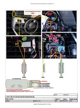
Vorsichtsmaßnahmen
      • Sachgemäße Installation der WFS400-LIN unter besonderer Beachtung
        dieser Vorsichtsmaßnahmen.
      • Betreiben Sie diese WFS400-LIN ausschließlich in dafür vorgesehenen KFZ.
      • Achten Sie auf korrekte Anschlüsse.
      • Verlegen Sie die Kabel so, dass sie nicht geknickt, gequetscht oder durch scharfe
        Kanten beschädigt werden können.
      • Installieren Sie die WFS400-LIN an einer sicheren Stelle, an der es beim Fahren
        nicht behindert und an dem es keinerlei Feuchtigkeit ausgesetzt wird. Benutzen Sie
        das mitgelieferte Installationsmaterial.
      • Achtung! Eine falsche Installation, kann die Elektronik des KFZ zerstören!
        Beachten Sie die Hinweise des KFZ-Herstellers. Diese WFS400-LIN ist
        ausschließlich für den Gebrauch in KFZ bestimmt.

    Umwelthinweise
      • Elektronische Altgeräte gehören nicht in die Mülltonne.
      • Wenn Sie dieses Gerät später entsorgen möchten, entfernen
        Sie sämtliche Kabel und senden Sie es an Ampire zurück.
      • Sie können dieses Gerät auch gemeinsam mit Ihrem
        Altwagen entsorgen. Ein Ausbau ist dann nicht erforderlich.
      • Die Verpackung ist recycelbar. Entsorgen Sie die Verpackung
        in einem dafür vorgesehenen Sammelsystem.

      Informationen zur Entsorgung von Elektro- und Elektronikgeräten und Batterien
      (anwendbar für Länder, die ein separates Sammelsystem übernommen haben)
      Wenn Sie dieses Produkt entsorgen wollen, entsorgen Sie es nicht über den
      normalen Hausmüll. Es gibt ein separates Sammelsystem für gebrauchte
      elektronische Geräte in Einklang mit den Rechtsvorschriften, die eine angemessene
      Behandlung, Verwertung und Recycling erfordern. Kontaktieren Sie Ihre lokale
      Behörde für Details bei der Suche nach eine Recycling-Anlage in Ihrer Nähe.
      Ordnungsgemäße Verwertung und Entsorgung trägt dazu bei, Ressourcen zu
      schonen und schädliche Auswirkungen auf unsere Gesundheit und die Umwelt zu
      verhindern.

      Hiermit erklärt Ampire Electronics GmbH & Co.KG, dass die Bluetooth
      Wegfahrsperre WFS400-LIN den Richtlinien 2014/30/EU, 2014/35/EU, 2014/53/EU
      und 2011/65/EU entspricht. Den vollständigen Text der EU-Konformitätserklärung
      ist unter der folgenden Internetadresse verfügbar: https://www.ce.ampire.de

2
                                            2021 ampire Electronics – Irrtum und technische Änderungen vorbehalten
DE
                                                       Inhaltsangabe
1. Einführung........................................................................................... 4
2. Lieferumfang........................................................................................5
   Lieferumfang des optionalen Bluetooth Transponders WFST400......................................................... 5
3. Konfiguration........................................................................................6
  Software Update...................................................................................................................................6
  Programmierung...................................................................................................................................7
4. Installation.......................................................................................... 8
5. Grundlagen........................................................................................ 10
6. Tastenkombination erstellen/ändern.......................................................... 11
7. Service Modus.................................................................................... 13
    Über Tastenkombination................................................................................................................... 13
11. Technische Daten............................................................................... 14
12. Notizen............................................................................................ 15

                                                                                                                                                        3
    2021 ampire Electronics – Irrtum und technische Änderungen vorbehalten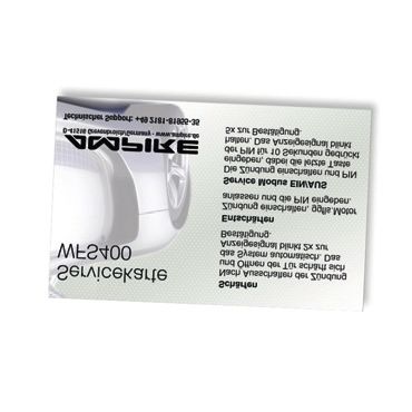
DE
                                           Einführung
     Herzlichen Glückwunsch und vielen Dank, dass Sie sich für ein Produkt aus dem Hause
     Ampire entschieden haben. Die Ampire WFS400-LIN ist eine digitale Wegfahrsperre, die das
     Wegfahren blockiert indem sie geeignete Befehle über den CAN/LIN-Bus an das Steuergerät
     des Fahrzeugs sendet. Es gibt drei Möglichkeiten, wie das Fahrzeug blockiert (abhängig von
     Fahrzeugmodell, Motor und Ausstattung):
     a) Startblockade – wird die WFS400-LIN nicht freigeschaltet verhindert sie das Starten des
        Motors.
     b) Blockade bei Bewegung – die Deaktivierung des Motors hängt vom vorhandenen
        Getriebe ab. In Fahrzeugen mit Automatikgetriebe wird der Motor abgeschaltet, sobald der
        Wahlhebel die Park- oder Neutralposition verlässt. Bei manuellem Getriebe wird der Motor
        abgeschaltet, sobald sich das Fahrzeug bewegt.
     c) Wahlhebelsperre - es wird verhindert, dass der Wahlhebel die Parkpositon verlässt.
     Achtung: Jeder Start- / Fahrversuch mit aktivierter Wegfahrsperre produziert Fehler, die ins
               Fahrzeug geschrieben werden! Das kann zur Folge haben, dass nach mehreren
               Fehlversuchen das Fahrzeug nicht mehr anspringt oder nur noch im Notlauf
               bewegt werden kann!
     Die Freischaltung der Wegfahrsperre erfolgt:

        durch Eingabe der Tastenkombination

                     1            2

                      3          4

 4
                                                2021 ampire Electronics – Irrtum und technische Änderungen vorbehalten
DE
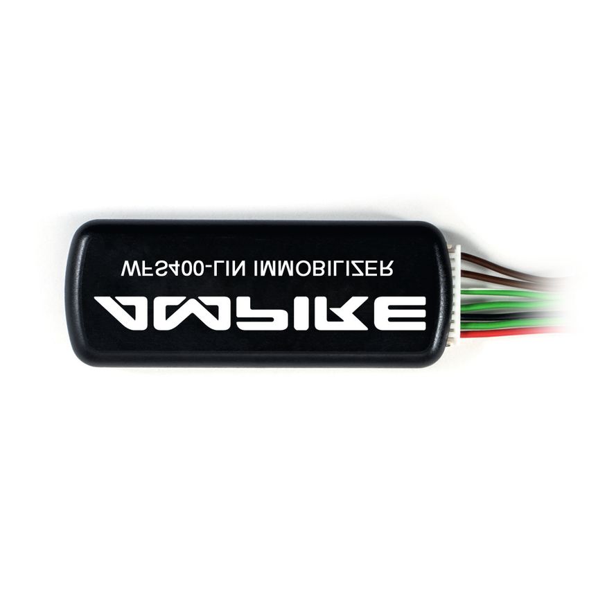
Lieferumfang
WFS400-LIN Zentrale Kabelbaum
Servicekarte Warnaufkleber
ampire
WFS400-LIN
German Engineering. Out of the ordinary.
Version 2
Bedienungsanleitung
Owner´s Manual
Scannen für die aktuellste
Bedienungsanleitung
Anleitung Fahrzeugspezifisches Anschlussdiagramm
5
2021 ampire Electronics – Irrtum und technische Änderungen vorbehalten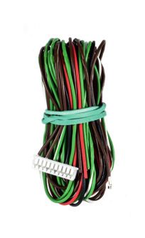
DE
                                          Konfiguration
      Software Update mit Hilfe des BL600 Programmierinterface (optional erhältlich)
      Wird die WFS400-LIN mit dem BL600 an einen Computer (mit Internetzugang)
      angeschlossen, kann die Firmware ggf. eine aktuellere Firmware aufgespielt und die
      Programmnummer eingespeichert werden. Alternativ kann die Programmnummer auch mit
      dem Taster in der Zentrale eingespeichert werden.
      Die WFS400-LIN muss immer auf Ihr Fahrzeug vorprogrammiert und mit der aktuellsten
      Software versehen sein. Es muss nur ein Update durchgeführt werden, wenn das Fahrzeug
      gewechselt wird.

                                     11120                    Lesen     Speichern      Update

                                     Benutzername                                    Anmelden
                                     Passwort                                         Speichern

                                     S/N: B97845EE6ADF0C04F3FE02F0573696 SOFT: 2021-06-21(v.1)
     Server                          Gerät: Ja (333_77_12)
                                     Anschluss: Ja (CMOS)
                                     Internet: Ja
                                     Update: Für diese Information anmelden
                                     Upgrade Zähler : 0

                                     Verfügbare Updates
               Internet
                                        - Deutsch - Fertig

                      USB

                                         BL600                                                        WFS400-LIN
                                     Programmierer                                                    Wegfahrsperre

      * BL600 kann nur die Firmware und damit die Daten der unterstützten Fahrzeuge
        aktualisieren. Es ist nicht in der Lage Funktionen der WFS400-LIN zu ändern.

 6
                                                             2021 ampire Electronics – Irrtum und technische Änderungen vorbehalten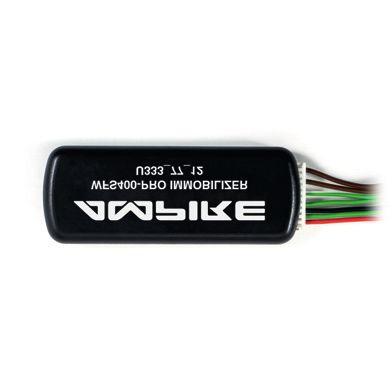
DE
                                                   Konfiguration
Programmierung der 5-stelligen fahrzeugspezifischen Programmnummer
Je nach Fahrzeug gibt es für die WFS400-LIN eine 5-stellige Programmnummer. Diese ist in
der Kompatibilitätsliste und im Verbindungsdiagramm aufgeführt. Die Programmnummer
wird mit der Programmiertaste und der LED (auf der rechten Seite) eingespeichert.
Achtung! Wurde bei der Bestellung ein Fahrzeugmodell angegeben? Wurde die 5-stellige
Programmnummer schon vorprogrammiert, muss diese nicht erneut eingespeichert
werden. (ggf. Prüfen)

                                  Taster                              CAN Taste (Rechtes Loch)
                                                                      Ist zum Programmieren der Zentrale.
                                  LED
                             ID         CAN                           Hinweis: Die Tasten mit einer
                                                                               Büroklammer drücken.

Programmnummer eingeben:
Taster drücken       1. Die Programmiertaste in der Zentrale drücken und gedrückt
                        halten, bis die LED anfängt schnell zu blinken. Jetzt kann die
          Taster        Taste losgelassen werden.
                 LED
           ID            CAN

LED blinkt                                 2. Die LED beginnt nun langsam zu blinken.
                Taster

                LED
           ID          CAN

                          3. Nachdem die LED exakt so oft geblinkt hat wie die erste Zahl der
Taster drücken               Programmnummer, die Programmiertaste wieder drücken und
                             gedrückt halten bis die LED anfängt, schnell zu blinken. Jetzt
           Taster            kann die Taste losgelassen werden.
            LED
           ID             4. Bitte wiederholen Sie die Punkte 2 und 3 bis die
                         CAN

                             Programmnummer vollständig eingegeben ist.
                          5. Die erfolgreiche Programmierung wird durch 10x Blinken der
                             LED bestätigt. Das Modul startet jetzt neu (2x blinken).
Programmnummer prüfen:
Die Programmiertaste in der Zentrale kurz drücken. Zuerst zeigt die LED durch Blinken die
Programmnummer an und dann wird der Status der 6 CAN-Verbindungen des Mikrochips
angezeigt (auch wenn nur 2 CAN-Linien angeschlossen sind). Folgende Blinksequenzen
zeigen den Status der 6 CAN-Linien an:
  1x Blinken – CAN-Daten wurden schon empfangen, aktuell werden aber keine Daten
               empfangen;
  2x Blinken – CAN-Bus verbunden, Daten werden empfangen;
  3x Blinken – CAN-Bus nicht verbunden, muss verbunden werden;
  4x Blinken – CAN-Bus nicht verbunden, keine Verbindung nötig.
                                                                                                            7
  2021 ampire Electronics – Irrtum und technische Änderungen vorbehalten
DE
Installation
gelb
LIN 1
Taster
LED
ID CAN
DIG1
8
2021 ampire Electronics – Irrtum und technische Änderungen vorbehaltenDE
Installation
PIN 1 Braun/Weiß CAN1-H
PIN 2 Braun (nicht eingesteckt*) EINGANG
PIN 3 Braun CAN1-L
PIN 4 nicht belegt
PIN 5 Grün/weiß CAN2-H
PIN 6 Gelb LIN 1
PIN 7 Grün CAN2-L
PIN 8 Schwarz MASSE
PIN 9 Grün AUSGANG (DIG 1)
PIN 10 Rot +12V permanent
PIN 1 Braun/Weiß CAN1-H
Dieses Kabel muss an den CAN-H angeschlossen werden.
PIN 2 Braun EINGANG*
Das braune Kabel, um die Wegfahrsperre ferngesteuert zu aktivieren, ist sicherheitshalber
nicht im Stecker eingesteckt. Bei Bedarf, wenn z.B. ein Ortungsgerät mit einem
entsprechenden Ausgang installiert wird, muss das beigelegte braune Kabel auf PIN 2
eingesteckt werden!
Wird auf PIN 2 des 10 PIN Steckers ein konstantes Massesignal, z.B. von einem GSM/GPS
Modul, gegeben, ist ist die Wegfahrsperre aktiv! Dabei ist es egal, ob sie vorher mit einer
Tastenkombination entschärft wurde, oder ob sie im Service Modus ist. Die Blockade greift,
sobald die Zündung einmal ausgeschaltet wurde und verhindert danach ein Weiterfahren.
PIN 3 Braun CAN1-L
Dieses Kabel muss an den CAN-L angeschlossen werden.
PIN 5 Grün/Weiß CAN2-H
Dieses Kabel muss an den CAN-H angeschlossen werden.
PIN 6 Gelb LIN 1
Dieses Kabel muss an den LIN Bus angeschlossen werden.
PIN 7 Grün CAN2-L
Dieses Kabel muss an den CAN-L angeschlossen werden.
PIN 8 Schwarz MASSE
Verbinden Sie dieses Kabel an einen Massepunkt vom Fahrzeug.
PIN 9 Grün AUSGANG (DIG 1)
Wenn der AUSGANG im Anschlussdiagramm als optional angegeben ist, liefert er Masse
(Imax = 1A) bei entschärfter Wegfahrsperre. Bei aktiver Wegfahrsperre besteht kein Kontakt.
PIN 10 Rot +12V konstant
Verbinden Sie dieses Kabel an einen mit einer Sicherung versehenen Dauerplusanschluss
vom Fahrzeug.
9
2021 ampire Electronics – Irrtum und technische Änderungen vorbehaltenDE
Grundlagen
Auf den speziellen Verbindungsdiagrammen für Ihr Fahrzeug sind die Programmnummer,
das jeweilige Indikator-Signal (ein optisches oder akustisches Signal) und die unterstützten
Tasten zur Entschärfung der Wegfahrsperre aufgeführt. Das Verbindungsdiagramm ist bei
der Lieferung enthalten.
Hinweis: Der Besitzer sollte die Anleitung und das fahrzeugspezifische
Verbindungsdiagramm bei Übergabe des Fahrzeugs ausgehändigt bekommen
und aufbewahren. Der Besitzer erhält somit die Information, welches Indikator-
Signal in seinem Fahrzeug ausgegeben wird und welche Tasten verwendet
werden können.
Achtung! Der Besitzer sollte die Position der Wegfahrsperre kennen für z.B. Software
Updates oder den Ausbau.
Schritt für Schritt Anschlussanleitung:
• Erst Masse und anschließend +12V Dauerplus anschließen.
• Jetzt kann die erforderliche Programmnummer mit Hilfe der Programmiertaste und der
LED in der WFS400-LIN eingegeben werden (falls nicht schon mit dem BL600
geschehen).
• CAN1 (CAN H & CAN L) anschließen,
• CAN2 (CAN H& CAN L) anschließen (falls erforderlich),
• falls erforderlich auch den LIN-Bus anschließen,
• Es ist auch möglich eine analoge Blockade über ein externes Relais und den analogen
Ausgang (max. 1A) zu installieren.
• Jetzt kann eine Tastenkombination gesetzt werden (siehe Seite 11).
Die Ampire Wegfahrsperre arbeitet nur dann mit dem CAN/LIN-Bus zusammen, wenn sie
ordnungsgemäß angeschlossen ist und Daten erhält. Es müssen immer sämtliche
Verbindungen, die im fahrzeugspezifischen Verbindungsdiagramm angegeben sind,
hergestellt werden. Die Übertragung wird ausgeführt, wenn die LED schnell blinkt. Durch
das Trennen der Wegfahrsperre von der Stromversorgung (Abziehen vom Stecker, Kappen
der 12V Leitung) ist die Wegfahrsperre deaktiviert, d.h. das Fahrzeug ist ungeschützt und
kann ganz normal gestartet werden. (außer der optionale DIG1 steuert ein optionales Relais
an).
10
2021 ampire Electronics – Irrtum und technische Änderungen vorbehaltenDE
Tastenkombination erstellen / ändern
Die Eingabe einer individuellen Tastenkombination ist Voraussetzung, damit sich die
Wegfahrsperre schärft. Die Tastenkombination ist eine frei wählbare Kombination aus
Tastendrücken von werksmäßig im Fahrzeug befindlichen Tasten. Die vom Fahrzeug
unterstützten Tasten finden Sie in den fahrzeugspezifischen Installationsdiagrammen.
Prozedur 1:
Ein 1. Zündung einschalten (Motor nicht eingeschaltet).
10 X treten 2. Das Gaspedal 10x durchtreten (wird das Gaspedal nicht
unterstützt Prozedur 2 durchführen).
Indikator Signal 3. Der Eintritt in die Eingabe der Tastenkombination wird durch
z.B. Blinker zwei Indikator-Signale bestätigt.
Drücken der Standard 4. Drücken Sie eine Kombination aus 1 – 15 der unterstützten
Fahrzeugtasten Tasten.
Aus 5. Die Zündung innerhalb von 10 Sekunden nach dem letzten
Tastendruck ausschalten. Das Ausschalten der Zündung
speichert die neue Tastenkombination. 1 Indikator-Signal
bestätigt das erfolgreiche Speichern der Tastenkombination.
Wird die Zündung nicht innerhalb von 10 Sekunden nach dem letzten Tastendruck
ausgeschaltet, werden die gedrückten Tasten ignoriert und nicht gespeichert.
Prozedur 2:
Ein 1. Zündung einschalten (Motor nicht eingeschaltet).
11
2021 ampire Electronics – Irrtum und technische Änderungen vorbehaltenDE
Tastenkombination erstellen / ändern
Taster Drücken 2. Programmnummer 11999 mit der Taste in der Zentrale
eingeben.
Taster
LED
ID CAN
Indikator Signal 3. Der Eintritt in die Eingabe der Tastenkombination wird durch
z.B. Blinker zwei Indikator-Signale bestätigt.
Drücken der Standard 4. Drücken Sie eine Kombination aus 1 – 15 der unterstützten
Fahrzeugtasten Tasten.
Aus 5. Die Zündung innerhalb von 10 Sekunden nach dem letzten
Tastendruck ausschalten. Das Ausschalten der Zündung
speichert die neue Tastenkombination. 1 Indikator-Signal
bestätigt das erfolgreiche Speichern der Tastenkombination.
Wird die Zündung nicht innerhalb von 10 Sekunden nach dem letzten Tastendruck
ausgeschaltet, werden die gedrückten Tasten ignoriert und nicht gespeichert.
Zum Prüfen, ob die eingegebene Tastenkombination korrekt gespeichert wurde, alle
angelernten und in Reichweite befindlichen Bluetooth Geräte ausschalten.
Ein 1. Zündung einschalten (Motor nicht eingeschaltet).
Drücken der Standard 2. Tastenkombination eingeben.
Fahrzeugtasten
Indikator Signal 3. Wenn ein Indikator-Signal das Entschärfen bestätigt,
z.B. Blinker wurde die Tastenkombination korrekt gespeichert. Wenn
nicht, wiederholen Sie die Prozedur.
12
2021 ampire Electronics – Irrtum und technische Änderungen vorbehaltenDE
Service Modus
Im Service Modus ist die Wegfahrsperren-Funktion des Gerätes deaktiviert. Er wird genutzt,
um das Fahrzeug z.B. in der Werkstatt abzugeben.
Service Modus mit der Tastenkombination Ein- / Ausschalten
Der Service Modus kann mithilfe der Tastenkombination aktiviert und deaktiviert werden,
indem bei der Eingabe die letzte Taste der Tastenkombination 10 Sekunden gedrückt
gehalten wird.
Ein 1. Schalten Sie die Zündung ein (Cockpit leuchtet komplett auf,
aber der Motor bleibt aus).
Drücken der Standard 2. Innerhalb von 30 Sekunden die Tastenkombination eingeben
Fahrzeugtasten und die letzte Taste für 10 Sekunden gedrückt halten.
Indikator Signal 3. 5 Indikator Signale bestätigen die Aktivierung des Service
z.B. Blinker Modus, ein Indikator Signal bestätigt die Deaktivierung.
ACHTUNG: Der Indikator zeigt im Service Modus nichts an! (und damit, dass das Fahrzeug
zur Zeit nicht geschützt ist). Nachdem das Fahrzeug aus der Werkstatt abgeholt
wurde, sollte unverzüglich der Service Modus deaktiviert werden, damit das
Fahrzeug wieder geschützt ist! Die normale Funktion der Wegfahrsperre wird wie
gewohnt vom Indikator angezeigt.
13
2021 ampire Electronics – Irrtum und technische Änderungen vorbehaltenDE
Technische Daten
Stromversorgung (12V) 9 – 16 V
Stromverbrauch aktiv (12V) 36,5 mA
Stromverbrauch eingeschlafen (12V) 10,0 mA
Stromverbrauch bei Zündung an (12V) 36,5 mA
Unterstützte CAN-Bus Geschwindigkeit 20 – 1000 kbit/s
Unterstützte UART Geschwindigkeit 1,2 – 125 kbit/s
Zeit bis eingeschlafen 5s
Zeit bis aufgewacht 800 µs
Anzahl der unterstützten CAN-Linien 2
1 Draht CAN-Bus (SAE J2411) JA
2 Draht CAN-Bus (SAE J1939) JA
Funktion mit J1708 (SAE J1587) JA
Überspannungsschutz am Ausgang PIN 9/10 JA
Belastbarkeit des Ausgangs PIN 9/10 1000 mA
Microchip Typ Automotive
Speicherkapazität für Transponder und/oder Smartphones 0 – 8 Stück
Arbeitstemperaturbereich -40°C - +85°C
Größe 52 x 21 x 7 mm
Interne Bezeichnung U333
Bluetooth Transponder (optional)
Stromversorgung 3V
Batterie Typ CR2032 (1x)
Kommunikationsfrequenz 2,36 – 2,50 GHz
Kommunikationsreichweite 2 – 10 m
Durchschnittlicher Stromverbrauch AN Max. 17,10 µA
Durchschnittlicher Stromverbrauch AUS Max. 4,60 µA
Voraussichtliche Arbeitszeit AN 12 – 18 Monate
Voraussichtliche Arbeitszeit AUS 36 – 72 Monate
Arbeitstemperaturbereich -40°C - +85°C
Größe 60 x 30 x 6 mm
Interne Bezeichnung U370
14
2021 ampire Electronics – Irrtum und technische Änderungen vorbehaltenDE
Platz für Notizen
Hier können Sie den Einbauort der WFS400-LIN einzeichnen.
ACHTUNG! Notieren Sie sich den neuen PIN Code, nachdem Sie ihn geändert haben.
Notieren Sie hier das Indikator Signal des Fahrzeugs.
15
2021 ampire Electronics – Irrtum und technische Änderungen vorbehaltenPrecautions
• Please install of the WFS400-LIN with special attention to these
precautions.
• Only operate the WFS400-LIN in intended vehicles.
• Ensure that the connections are correct.
• Lay the cables so that they can not be kinked, pinched, crushed or otherwise
damaged by sharp edges.
• Install the WFS400-LIN in a safe position that does not hinder driving and is not
exposed to moisture. Use the supplied installation material.
• Danger! An Incorrect installation may destroy the electronics of the vehicle!
Observe the instructions of the vehicle manufacturer. This WFS400-LIN is
exclusively for use in vehicles.
Environmental Reference
• Old electronic devices do not belong in the bin.
• If you want to dispose this equipment later, remove all cables
and send it back to Ampire or bring it to a collection point for
old electronic devices.
• You can also dispose this device together with your old car;
removal is unnecessary.
• The packaging can be recycled. Dispose the packaging
in a dedicated collection system.
Hereby Ampire Electronics GmbH & Co.KG declares that the immobilizer WFS400-LIN
complies with the directives 2014/30/EU, 2014/35/EU,2014/53/EU and 2011/65/EU. The full
text of the EU Declaration of Conformity in German language is available at the following
Internet address: https://www.ce.ampire.de
16
2021 ampire Electronics – Subject to technical changesEN
Summary
1. Introduction........................................................................................ 18
2. Box contents....................................................................................... 19
Box contents of the optional Bluetooth transponder WFST400...........................................................19
3. Configuration...................................................................................... 20
Software Update................................................................................................................................. 20
Programming...................................................................................................................................... 21
4. Installation.........................................................................................22
5. Basics...............................................................................................24
6. Create / change a button combination......................................................... 25
9. Service mode...................................................................................... 27
Via button combination..................................................................................................................... 27
11. Technical specifications....................................................................... 28
12. Notes.............................................................................................. 29
17
2021 ampire Electronics – Subject to technical changesEN
Introduction
Congratulations and thank you for choosing an Ampire product. The Ampire WFS400-LIN is
a digital immobilizer that sends specific commands to the vehicle's control unit via the
CAN/LIN bus in order to prevend the vehicle from driving without authorization. There are
three different ways to block the car from driving away (depending on the vehicle model,
engine and equipment):
a) Engine lock - if the WFS400-LIN is not disarmed, it prevents the motor from starting.
b) Block movement - the engine shutdown depends on the existing gearbox. In vehicles with
automatic transmissions, the engine is shutdown as soon as the gear
selector leaves the park or neutral position. With a manual
transmission, the engine is shutdown as soon as the vehicle starts
moving.
c) Gear selector lock - it prevents the gear selector from leaving the parking position.
Attention: While the immobilizer is armed, every start / drive attempt produces errors that
are written into the vehicle! After several unsuccessful attempts this can lead to
the vehicle no longer starting or it can only be moved in emergency mode.
The disarming of the immobilizer occurs:
by entering the button combination
1 2
3 4
18
2021 ampire Electronics – Subject to technical changesEN
Box contents
WFS400-LIN main unit Wiring harness
Service card Warning sticker
ampire
WFS400-LIN
German Engineering. Out of the ordinary.
Version 2
Bedienungsanleitung
Owner´s Manual
Scannen für die aktuellste
Bedienungsanleitung
Manual Vehicle-specific connection diagram
19
2021 ampire Electronics – Subject to technical changesEN
DE
Configuration
Software update using the BL600 programming interface (optionally available)
If the BL600 is connected to a computer (with internet access) and the WFS400-LIN, the
firmware can be updated and the program number can be saved. Alternatively, the program
number can also be entered using the button on the main unit.
The WFS400-LIN must always be preprogrammed for your vehicle and provided with the
latest firmware. An update only needs to be carried out when the vehicle is changed.
11120 Read Save Update
User name Login
Password save
S/N: B97845EE6ADF0C04F3FE02F0573696 SOFT: 2021-06-21(v.1)
Server Device: Yes (333_77_12)
Connection: Yes (CMOS)
Internet: Yes
Update: Register for this information
Upgrade counter: 0
Available updates
Internet
- Englisch - Ready
USB
BL600 WFS400-LIN
Programmer Immobilizer
* BL600 can only update the firmware and thus the data of the supported vehicles. It is not
able to change functions of the WFS400-LIN.
20
2021 ampire Electronics – Subject to technical changesEN
Configuration
Programming of the 5-digit vehicle-specific program number
Depending on the vehicle, there is a 5-digit program number for the WFS400-LIN. This is
shown in the compatibility list and in the connection diagram. The program number is
entered using the programming button and the LED (on the right-hand side).
Attention!! Did you order a vehicle specific programmed unit ? If so, the unit is already
preconfigured to work with your vehicle (check if necessary)
Switch CAN button (right hole)
Is for programming the main unit.
LED
ID CAN Note: Press the buttons with a paper clip.
Enter program number:
Press button 1. Press the programming button on the main unit and keep it
pressed until the LED starts to flash rapidly. Release the button.
Switch
LED
ID CAN
LED flashes 2. The LED will start flashing slowly.
Switch
LED
ID CAN
3. After the LED has flashed exactly as often as the first digit of
Press button the program number, press the programming button again and
hold it down until the LED starts to flash quickly. Now the
Switch button can be released.
ID
LED
CAN 4. Please repeat steps 2 and 3 until the program number has
been entered completely.
5. Successful programming is confirmed by 10 flashes of the LED.
The module now restarts (2x flashes).
Check program number:
Press the programming button shortly. First, the module shows (flashes) the 5 digit
program number and then the status of the microcontrollers 6 CAN connections (even when
a certain device has access to only 2 CANs). The following flashing sequences show the
status of the 6 CAN lines:
1 LED flash – CAN bus data was detected in the past, currently not receiving any data;
2 LED flashes – CAN bus connected, receiving data;
3 LED flashes – CAN bus not connected, connection required;
4 LED flashes – CAN bus not supported, does not need connection.
21
2021 ampire Electronics – Subject to technical changesEN
Installation
brown
brown/white
brown
LIN 1
yellow
Switch green/white
LED
ID CAN
green
black
red
DIG1
green
Additional
blocking
relay
22
2021 ampire Electronics – Subject to technical changesEN
Installation
PIN 1 Brown/White CAN1-H
PIN 2 Brown (not plugged in *) INPUT
PIN 3 Brown CAN1-L
PIN 4 not used
PIN 5 Green/White CAN2-H
PIN 6 Yellow LIN 1
PIN 7 Green CAN2-L
PIN 8 Black GROUND
PIN 9 Green OUTPUT (DIG 1)
PIN 10 Red +12V permanent
PIN 1 Brown/White CAN1-H
This wire must be connected to the CAN-H.
PIN 2 Brown INPUT*
For safety reasons, the brown wire which can arm the immobilizer remotely, is not plugged
in the connector. If for example a tracking device with a corresponding output is installed,
the enclosed brown cable must/can be plugged into PIN 2.
If a constant ground signal is given to PIN 2 of the 10 PIN connector, e.g. from a GSM /
GPS module, the immobilizer is armed! It doesn't matter whether it was previously
deactivated with a button combination or if it was in service mode. The immobilizer is active
as soon as the ignition is switched off and prevents further driving afterwards.
PIN 3 Brown CAN1-L
This wire must be connected to the CAN-L.
PIN 5 Green/White CAN2-H
This wire must be connected to the CAN-H.
PIN 6 Yellow LIN 1
This wire must be connected to the LIN-Bus.
PIN 7 Green CAN2-L
This wire must be connected to the CAN-L.
PIN 8 Black Ground
Main unit power supply
PIN 9 Green OUTPUT (DIG 1)
If the OUTPUT is specified as optional in the connection diagram, it provides ground (Imax =
1A) when the immobilizer is disarmed. There is no contact when the immobilizer is armed.
PIN 10 Red +12V konstant
Connect this wire to a secured permanent positive connection provided on the vehicle.
23
2021 ampire Electronics – Subject to technical changesEN
Basics
The program number, the indicator signal (an optical or acoustic signal) and the supported
switches for deactivating the immobilizer are listed on the vehicle-specific connection
diagram. The connection diagram is included with the order.
Note: The owner should be given the instructions and the vehicle-specific connection
diagram when the vehicle is handed over and they should be stored in a secure
location. With these documents the owner of the vehicle knows which indicator
signal is used and which switches can be used in his car.
Attention! The owner should know the position of the immobilizer, for e.g. software
updates or removal.
Step by step connection instructions:
• First connect ground and then + 12V permanent.
• Now the required program number can be entered using the programming button and the
LED in the WFS400-LIN main unit (if not already done with the BL600).
• connect CAN1 (CAN H & CAN L),
• connect CAN2 (CAN H& CAN L) (if necessary),
• if necessary also connect the LIN Bus,
• it is also possible to install an analog starter kill by using an external relay and the analog
output (max. 1A).
• a button combination can now be set (see page 11).
The Ampire immobilizer only works with the CAN/LIN BUS if it is properly connected and
receives data. The transmission is executed when the LED flashes rapidly. You must always
use all connections specified in the vehicle-specific connection diagram. By disconnecting
the immobilizer from the power supply (unplugging from the connector, cap the 12V cable),
the immobilizer is deactivated, i.e. the vehicle is unprotected and can be can be started
normally. The vehicle now is unprotected, except an optional relay is connected to DIG1 and
DIG1 is marked as " optional" , too.
24
2021 ampire Electronics – Subject to technical changesEN
Create / change button combination
The entry of an individual button combination is a prerequisite for the immobilizer to arm
itself. The button combination is a freely selectable combination of pushes from factory-
installed switches in the vehicle. The switches supported by the vehicle can be found in the
vehicle-specific connection diagrams.
Procedure 1:
On 1. Switch on the ignition (do not start the engine).
10 X to step 2. Depress the accelerator pedal 10 times (if the accelerator pedal
is not supported, carry out procedure 2).
Indicator signal 3. Entering the button combination setup confirmed by two
e.g. turn signals indicator signals.
Pressing the standard 4. Press a combination of 1-15 supported switches.
Vehicle switches
Off 5. Switch off the ignition within 10 seconds of the last push.
Switching off the ignition saves the new button combination.
1 indicator signal confirms the successful saving of the button
combination.
If the ignition is not switched off within 10 seconds after the last push, the switches pressed
are ignored and not saved.
Procedure 2:
On 1. Switch on the ignition (do not start the engine).
25
2021 ampire Electronics – Subject to technical changesEN
Create / change key combination
Press button 2. Enter the program number 11999 with the button in the main
unit.
Switch
LED
ID CAN
Indicator signal 3. Entering the button combination setup is confirmed by two
e.g. turn signals indicator signals.
Pressing the standard 4. Press a combination of 1-15 of the supported switches.
Vehicle switches
Off 5. Switch off the ignition within 10 seconds of the last push.
Switching off the ignition saves the new button combination.
1 indicator signal confirms the successful saving of the button
combination.
If the ignition is not switched off within 10 seconds after the last push, the switches pressed
are ignored and not saved.
To check whether the entered button combination has been saved correctly, switch off all
paired Bluetooth devices that are within range.
Ein 1. Switch on the ignition (do not start the engine).
Pressing the standard 2. Enter the button combination.
Vehicle switches
Indicator signal 3. If an indicator signal confirms the disarming, the button
e.g. turn signals combination has been saved correctly. If not, repeat the
procedure.
26
2021 ampire Electronics – Subject to technical changesEN
Service Modus
The immobilizer is deactivated in service mode. It is used when servicing the vehicle, for
example.
Service mode with the button combination on / off
The service mode can be activated and deactivated using the button combination by holding
down the last key of the button combination for 10 seconds.
On 1. Turn on the ignition (do not turn the engine on).
Pressing the standard 2. Within 30 seconds enter the button combination and hold
Vehicle switches down the last switch for 10 seconds.
Indicator signal 3. 5 indicator signals confirm the activation of the service mode,
e.g. turn signals an indicator signal confirms the deactivation.
ATTENTION: The indicator does not show anything in service mode! (and with it that the
vehicle is currently not protected). After the vehicle has been picked up from
the workshop, the service mode should be deactivated immediately so that the
vehicle is protected again! The normal function of the immobilizer is shown by
the indicator as usual.
27
2021 ampire Electronics – Subject to technical changesEN
DE
Technical specifications
Power supply (12V) 9 – 16 V
Current consumption in work mode (12V) 36,5 mA
Current consumption in sleep mode (12V) 10,0 mA
Current consumption when ignition ON (12V) 36,5 mA
Supported CAN BUS speed 20 – 1000 kbit/s
Supported UART speed 1,2 – 125 kbit/s
Transition time to sleep mode 5s
Time to wakeup 800 µs
Number of supported CAN BUSes 2
1−wire CAN BUS support (SAE J2411) YES
2−wire CAN BUS support (SAE J1939) YES
Support of J1708 (SAE J1587) YES
Overcurrent protection of pin 9/10 output YES
Current rating of pin 9/10 output 1000 mA
Microcontroller type Automotive
Memory capacity of ID tags and / or smartphones 0 – 8 pieces
Operating temperature range -40°C - +85°C
Dimensions 52 x 21 x 7 mm
PCB marking U322
Bluetooth Transponder (optional)
Supply voltage 3V
Battery type CR2032 (1x)
Wireless communication frequency 2,36 – 2,50 GHz
Wireless communication range 2 – 10 m
Average power consumption in ON mode Max. 17,10 µA
Average power consumption in OFF mode Max. 4,60 µA
Estimated working time in ON mode 12 – 18 Months
Estimated working time in OFF mode 36 – 72 Months
Operating temperature range -40°C - +85°C
Dimensions 60 x 30 x 6 mm
PCB marking U370
28
2021 ampire Electronics – Subject to technical changesDE
Notes
Here you can mark the installation location of the WFS400-LIN.
ATTENTION! Make a note of the new PIN code after changing it.
Note the vehicle's indicator signal here.
29
2021 ampire Electronics – Subject to technical changesEN
DE
Notes
30
2021 ampire Electronics – Subject to technical changesDE
Notes
31
2021 ampire Electronics – Subject to technical changesampire
WFS400-LIN
Seit der Firmengründung im Jahr 1987 hat AMPIRE ELECTRONICS nur das eine Ziel, dem
Kunden die bestmöglichen Autoalarm-, Autohifi- und Multimediaprodukte zu liefern, die auf
dem internationalen Markt erhältlich sind.
Alle Fertigungsstätten und Zulieferer sind nach ISO-9001 bzw. QS-9000 zertifiziert.
Die Qualitätsprodukte von AMPIRE werden weltweit verkauft.
Ein Kundenservice ist in vielen Ländern erhältlich. Für nähere Informationen über
Vertretungen im Ausland wählen Sie: +49-2181-81955-0.
Wir fokussieren auf zukunftsorientierte Entwicklung anwenderfreudlicher Produkte.
Unser hoher Anspruch an Qualität, Funktionalität und Design zeichnet unsere Erzeugnisse
aus. „German Development" wird bei AMPIRE wörtlich genommen.
Since its founding in 1987 Ampire Electronics has only one goal, to provide the best possible
car alarm, car hifi and Multimedia products, which are available on the international market.
All manufacturing facilities and suppliers are certified according to ISO 9001 and QS-9000.
Ampire quality products are sold worldwide.
An Ampire customer service is available in many countries.
For more information about distributors in your territory please call: + 49-2181-81955-0.
We are focused on future oriented development of user friendly products.
The outstanding high quality standards, functionalities and designs of our products are
unique in the market. " German Development" is taken literally in AMPIRE.
Langwadener Straße 60
D-41516 Grevenbroich
info@ampire.de
Support
+49 2181-81955-0
support@ampire.de
www.ampire.de
© 2021 AMPIRE ELECTRONICS. Alle Rechte vorbehalten. Nachdruck, auch auszugsweise, nur mit schriftlicher Genehmigung. /
All rights reserved. Reproduction in whole or in part without written permission.Sie können auch lesen