G450 S | G600 S - DE Betriebsanleitung / EN Operating instructions - DE Schweißstromquelle EN Welding power source - JESS WELDING
←
→
Transkription von Seiteninhalten
Wenn Ihr Browser die Seite nicht korrekt rendert, bitte, lesen Sie den Inhalt der Seite unten
Jäckle & Ess System GmbH

DE Betriebsanleitung / EN Operating instructions

G450 S | G600 S
DE Schweißstromquelle
EN Welding power source

                                          www.jess-welding.com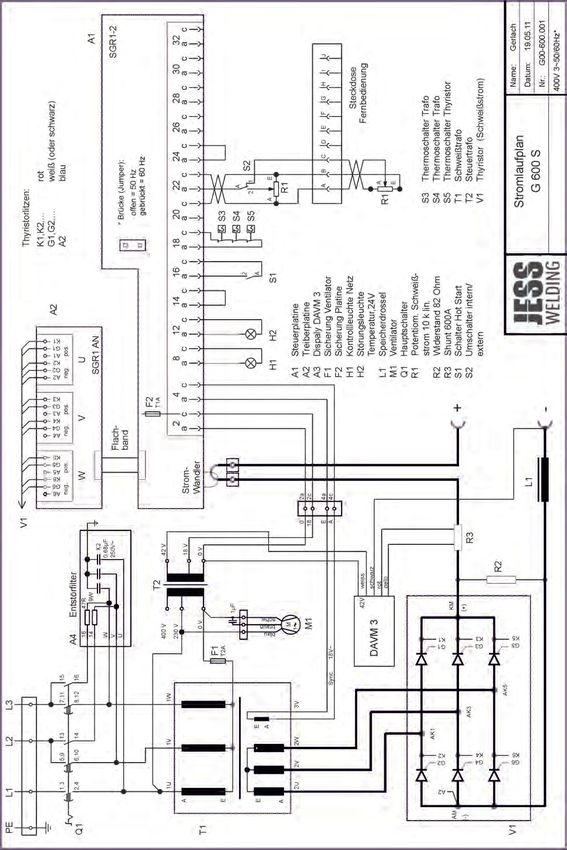
DE                                                                                                             G450 S | G600 S

 Original Betriebsanleitung
 Der Hersteller behält sich das Recht vor, jederzeit und ohne vorherige Mitteilung Änderungen an dieser Betriebsanleitung
 durchzuführen, die durch Druckfehler, eventuelle Ungenauigkeiten der enthaltenen Informationen oder Verbesserung dieses Produktes
 erforderlich werden. Diese Änderungen werden jedoch in neuen Ausgaben berücksichtigt.Alle in der Betriebsanleitung genannten
 Handelsmarken und Schutzmarken sind Eigentum der jeweiligen Besitzer/Hersteller.Die Kontaktdaten der Jäckle & Ess System GmbH
 Ländervertretungen und Partner weltweit entnehmen Sie bitte unserer Homepage www.jess-welding.com

1        Identifikation                                 DE-3         5       Funktionsbeschreibung G450 S
1.1      Kennzeichnung                                  DE-3                 und G600 S                                     DE-10

2        Sicherheit                                     DE-3         6       Inbetriebnahme                                 DE-10
2.1      Bestimmungsgemäße Verwendung                   DE-3         6.1     Netzanschluss                                  DE-12
2.2      Pflichten des Betreibers                       DE-3         6.2     Schweißkabel anschließen                       DE-12
2.3      Persönliche Schutzausrüstung                   DE-3         6.3     Schweißen                                      DE-12
2.4      Entsorgung der Maschine                        DE-3
2.5      Klassifizierung der Warnhinweise               DE-4         7       Betrieb                                        DE-13
2.6      Produktsicherheit                              DE-4         7.1     Bedienelemente                                 DE-13
2.7      Warn- und Hinweisschilder                      DE-5         7.1.1   Bedienelemente G450 S                          DE-13
2.8      Angaben für den Notfall                        DE-5         7.1.2   Bedienelemente G600 S                          DE-14

3        Produktbeschreibung                            DE-6         8       Wartung und Reinigung                          DE-15
3.1      Technische Daten                               DE-6
3.1.1    G450 S                                         DE-6         9       Anhang                                         DE-16
3.1.2    G600 S                                         DE-7         9.1     Ersatzteilliste G450 S und G600 S              DE-16
3.1.3    Umgebungsbedingungen                           DE-7         9.1.1   Ersatzteilliste G450 S                         DE-16
3.2      Typenschild                                    DE-8         9.1.2   Ersatzteilliste G600 S                         DE-20
3.2.1    Typenschild G450 S                             DE-8
3.2.2    Typenschild G600 S                             DE-8         10      Schaltpläne                                    DE-23
3.3      Verwendete Zeichen und Symbole                 DE-9         10.1    Schaltplan G450 S                              DE-23
                                                                     10.2    Schaltplan G600 S                              DE-24
4        Lieferumfang                                   DE-9
4.1      Transport                                      DE-9
4.2      Lagerung                                       DE-9

DE - 1                                                                                                     BA-0003 • 2020-12-01
G450 S | G600 S                                                                                              1 Identifikation

1 Identifikation
                       Die Schweißgleichrichter G450 S und G600 S sind ausschließlich für das Elektrodenschweißen, das
                       Fugenhobeln und das WIG-Schweißen im Lift-Arc-Betrieb (ohne HF) mit Gleichstrom bestimmt.

1.1 Kennzeichnung
                       Das Produkt erfüllt die geltenden Anforderungen des jeweiligen Marktes für das Inverkehrbringen. Sofern
                       es einer entsprechenden Kennzeichnung bedarf, ist diese am Produkt angebracht.

2 Sicherheit
                       Beachten Sie das beiliegende Dokument „Safety instructions“.

2.1 Bestimmungsgemäße Verwendung
                       Das in dieser Anleitung beschriebene Gerät darf ausschließlich zu dem in der Anleitung beschriebenen
                       Zweck in der beschriebenen Art und Weise verwendet werden. Beachten Sie dabei die Betriebs-, Wartungs-
                       und lnstandhaltungsbedingungen.
                       • Jede andere Verwendung gilt als nicht bestimmungsgemäß.
                       • Eigenmächtige Umbauten oder Veränderungen zur Leistungssteigerung sind nicht zulässig.

2.2 Pflichten des Betreibers
                       Lassen Sie nur Personen am Gerät arbeiten:
                       • die mit den grundlegenden Vorschriften über Arbeitssicherheit und Unfallverhütung vertraut sind
                       • die in die Handhabung des Geräts eingewiesen wurden
                       • die diese Bedienungsanleitung gelesen und verstanden haben
                       • die das beiliegende Dokument „Safety instructions“ gelesen und verstanden haben
                       • die entsprechend ausgebildet wurden
                       • die aufgrund ihrer fachlichen Ausbildung, Kenntnisse und Erfahrungen mögliche Gefahren erkennen
                         können
                       Halten Sie andere Personen vom Arbeitsbereich fern.
                       Beachten Sie die Arbeitssicherheitsvorschriften des jeweiligen Landes.
                       • Beachten Sie die Vorschriften zur Arbeitssicherheit und zur Unfallverhütung. Bei diesem Gerät handelt
                         es sich nach DIN EN 60974-10 um eine Klasse A Schweißeinrichtung. Klasse A Schweißeinrichtungen
                         sind nicht für den Gebrauch in Wohnbereichen vorgesehen, in denen die Stromversorgung über ein
                         öffentliches Niederspannungs-Versorgungssystem erfolgt. Elektromagnetische Störungen können hier
                         die Folge sein, die Geräteschäden und Fehlfunktionen auslösen. Verwenden Sie das Gerät nur in
                         Industriegebieten.

2.3 Persönliche Schutzausrüstung
                       Um Gefahren für den Nutzer zu vermeiden, wird in dieser Anleitung das Tragen von persönlicher
                       Schutzausrüstung (PSA) empfohlen.
                       Sie besteht aus Schutzanzug, Schutzbrille, Atemschutzmaske Klasse P3, Schutzhandschuhen und
                       Sicherheitsschuhen.

2.4 Entsorgung der Maschine
                       Geben Sie Elektro-Altgeräte nicht zu normalem Hausmüll! Unter der Berücksichtigung der EG-Richtlinie für
                       Elektro- und Elektronik Altgeräte und ihrer Umsetzung in Anlehnung an das nationale Recht müssen
                       Elektroausrüstungen, die das Ende ihrer Lebensdauer erreicht haben, getrennt gesammelt und einer
                       zuständigen, umweltverantwortlichen Wiederverwertungsanlage übergeben werden. Gemäß den
                       Anweisungen der Gemeindebehörden ist der Eigentümer der Ausrüstung verpflichtet, einer regionalen
                       Sammelzentrale eine außer Betrieb gesetzte Einheit zu übergeben. Weitere Information finden Sie im
                       Internet unter dem Stichwort „WEEE“.

BA-0003 • 2020-12-01                                                                                                       DE - 3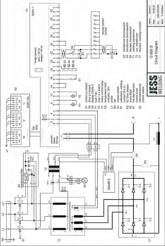
2 Sicherheit                                                                                          G450 S | G600 S

2.5 Klassifizierung der Warnhinweise
                   Die in der Betriebsanleitung verwendeten Warnhinweise sind in vier verschiedene Ebenen unterteilt und
                   werden vor potentiell gefährlichen Arbeitsschritten angegeben. Geordnet nach abnehmender Wichtigkeit
                   bedeuten sie Folgendes:

                          GEFAHR
                    Bezeichnet eine unmittelbar drohende Gefahr. Wenn sie nicht gemieden wird, sind Tod oder schwerste
                    Verletzungen die Folge.

                          WARNUNG
                    Bezeichnet eine möglicherweise gefährliche Situation. Wenn sie nicht gemieden wird, können schwere
                    Verletzungen die Folge sein.

                          VORSICHT
                    Bezeichnet eine möglicherweise schädliche Situation. Wenn sie nicht gemieden wird, können leichte
                    oder geringfügige Verletzungen die Folge sein.

                    HINWEIS
                    Bezeichnet die Gefahr, dass Arbeitsergebnisse beeinträchtigt werden oder Sachschäden an der
                    Ausrüstung die Folge sein können.

2.6 Produktsicherheit
                   Das Produkt wurde nach dem Stand der Technik und den anerkannten sicherheitstechnischen Normen und
                   Richtlinien entwickelt und gefertigt. Vor unvermeidbaren Restrisiken für Anwender, Dritte, Geräte oder
                   andere Sachwerte wird in dieser Betriebsanleitung gewarnt. Die Missachtung dieser Hinweise kann zu
                   Gefahren für das Leben und die Gesundheit von Personen, zu Umweltschäden oder Sachschäden führen.
                   • Das Produkt darf nur in unverändertem und einwandfreiem technischen Zustand innerhalb der in dieser
                     Anleitung beschriebenen Grenzen betrieben werden.
                   • Halten Sie stets die in den technischen Daten angegebenen Grenzwerte ein. Überlastungen führen zu
                     Zerstörungen.
                   • Sicherheitseinrichtungen am Gerät dürfen niemals demontiert, überbrückt oder in anderer Weise
                     umgangen werden.
                   • Verwenden Sie beim Gebrauch im Freien einen geeigneten Schutz gegen Witterungseinflüsse.
                   • Überprüfen Sie das Elektrogerät auf eventuelle Beschädigungen und auf einwandfreie und
                     bestimmungsgemäße Funktion.
                   • Setzen Sie das Elektrogerät nie dem Regen aus und vermeiden Sie eine feuchte oder nasse Umgebung.
                   • Schützen Sie sich vor Stromunfällen, indem Sie isolierende Unterlagen verwenden und trockene
                     Kleidung tragen.
                   • Verwenden Sie das Elektrogerät niemals in Bereichen, wo Brand- oder Explosionsgefahr besteht.
                   • Lichtbogenschweißen kann Augen, Haut und Gehör schädigen! Tragen Sie deshalb bei Arbeiten mit
                     dem Gerät stets die vorgeschriebene Schutzausrüstung.
                   • Alle Metalldämpfe, besonders Blei, Cadmium, Kupfer und Beryllium, sind gesundheitsschädlich! Sorgen
                     Sie für ausreichende Belüftung oder Absaugung. Achten Sie immer auf die Einhaltung der gesetzlichen
                     Grenzwerte.
                   • Spülen Sie Werkstücke, die mit chlorierten Lösungsmitteln entfettet wurden, mit klarem Wasser ab.
                     Ansonsten besteht die Gefahr der Phosgengasbildung. Stellen Sie keine chlorhaltigen Entfettungsbäder
                     in der Nähe des Schweißplatzes auf.
                   • Halten Sie die allgemeinen Brandschutzbestimmungen ein und entfernen Sie vor Arbeitsbeginn
                     feuergefährliche Materialien aus der Umgebung des Schweißarbeitsplatzes. Halten Sie geeignete
                     Brandschutzmittel am Arbeitsplatz bereit.

DE - 4                                                                                           BA-0003 • 2020-12-01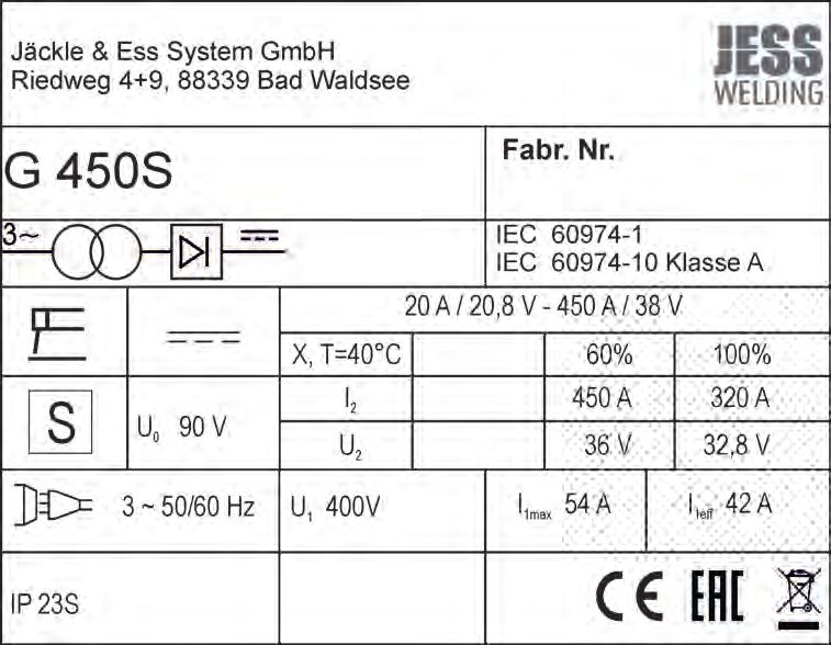
G450 S | G600 S                                                                                            2 Sicherheit

2.7 Warn- und Hinweisschilder
                       Am Produkt befinden sich folgende Warn- und Hinweisschilder:

                        Symbol                 Bedeutung
                                               Betriebsanleitung lesen und beachten!

                                               Vor dem Öffnen Netzstecker ziehen!

                                               Warnung vor heißer Oberfläche

2.8 Angaben für den Notfall
                       Unterbrechen Sie im Notfall sofort folgende Versorgungen:
                       • Elektrische Energieversorgung
                       • Druckluftzufuhr
                       • Gaszufuhr
                       Weitere Maßnahmen entnehmen Sie der Betriebsanleitung der Stromquelle oder der Dokumentation
                       weiterer Peripheriegeräte.

BA-0003 • 2020-12-01                                                                                              DE - 5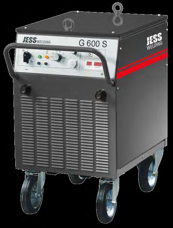
3 Produktbeschreibung                                                                  G450 S | G600 S

3 Produktbeschreibung

3.1 Technische Daten

3.1.1 G450 S

                        Abb. 1        G450 S

                        Tab. 1        Technische Daten G450 S

                        Stromquelle                      G450 S
                        Netzspannung, 3 Phasen           400 V, 50/60 Hz
                        Sicherung                        63 A träge
                        max. Leistungsaufnahme           39 kVA
                        Einstellbereich                  20–450 A, stufenlos
                        Arbeitsspannung                  21–38 V
                        Leerlaufspannung                 90 V
                        Einschaltdauer 60 %              450 A / 38 V
                        Einschaltdauer 100 %             320 A / 33 V
                        Schutzart                        IP22
                        Isolationsklasse                 H (180 °C)
                        Kühlart                          F
                        Gewicht                          145 kg
                        Maße L × B × H                   600 × 430 × 710

                          • Herstellung gemäß Euronorm EN 60974-1 und EN 60974-10

DE - 6                                                                              BA-0003 • 2020-12-01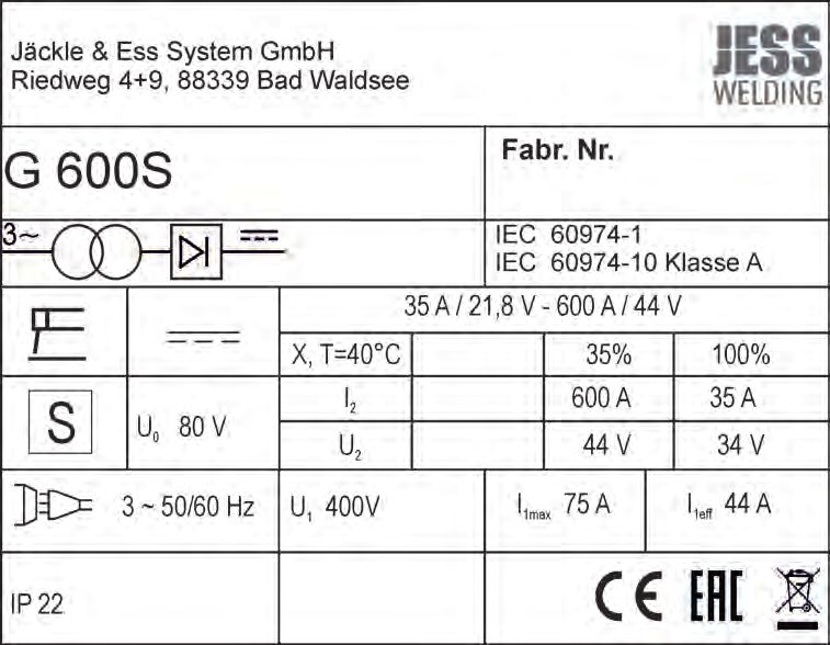
G450 S | G600 S                                                                                  3 Produktbeschreibung

3.1.2 G600 S

                       Abb. 2         G600 S

                       Tab. 2         Technische Daten G600 S

                        Stromquelle                        G600 S
                        Netzspannung, 3 Phasen             400 V, 50/60 Hz
                        Sicherung                          63 A, träge
                        max. Leistungsaufnahme             50 kVA
                        Einstellbereich                    35–600 A, stufenlos
                        Arbeitsspannung                    21–44 V
                        Leerlaufspannung                   80 V
                        Einschaltdauer 35 %                600 A / 44 V
                        Einschaltdauer 100 %               350 A / 34 V
                        Schutzart                          IP22
                        Isolationsklasse                   H (180 °C)
                        Kühlart                            F
                        Gewicht                            210 kg
                        Maße L × B × H                     810 × 500 × 850

                          • Herstellung gemäß Euronorm EN 60974-1 und EN 60974-10

3.1.3 Umgebungsbedingungen
                       Die Schweißstromquelle darf nur bei einer Temperatur zwischen −10 °C und +40 °C, sowie einer relativen
                       Luftfeuchte von bis 50 % bei +40 °C oder bis 90 % bei +20 °C betrieben werden. Die Umgebungsluft
                       muss frei von unüblichen Mengen an Staub, Säuren, korrosiven Gasen oder Substanzen usw. sein, soweit
                       diese nicht beim Schweißen entstehen.

BA-0003 • 2020-12-01                                                                                                   DE - 7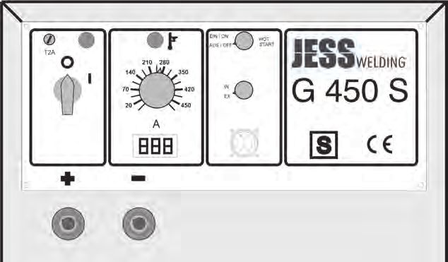
3 Produktbeschreibung                                                                                     G450 S | G600 S

3.2 Typenschild

3.2.1 Typenschild G450 S
                        Die Schweißstromquelle ist am Gehäuse mit einem Typenschild wie folgt gekennzeichnet:
                        Abb. 3        Typenschild G450 S

3.2.2 Typenschild G600 S
                        Die Schweißstromquelle ist am Gehäuse mit einem Typenschild wie folgt gekennzeichnet:
                        Abb. 4        Typenschild G600 S

DE - 8                                                                                               BA-0003 • 2020-12-01
G450 S | G600 S 4 Lieferumfang
3.3 Verwendete Zeichen und Symbole
Symbol Beschreibung
• Aufzählungssymbol für Handlungsanweisungen und Aufzählungen
Querverweissymbol verweist auf detaillierte, ergänzende oder weiterführende
Informationen
1. Handlungsschritt/e im Text, die der Reihenfolge nach durchzuführen sind
4 Lieferumfang
Tab. 3 Lieferumfang
• Schweißstromquelle • Betriebsanleitung • Beipackzettel „allgemeine
Sicherheitsinformationen“
Ausrüst- und Verschleißteile separat bestellen.
Bestelldaten und Identnummern der Ausrüst- und Verschleißteile entnehmen Sie den aktuellen
Bestellunterlagen. Kontakt für Beratung und Bestellung finden Sie im Internet unter www.jaeckleess.com.
4.1 Transport
Der Lieferumfang wird vor dem Versand sorgfältig geprüft und verpackt, jedoch sind Beschädigungen
während des Transportes nicht auszuschließen.
Eingangskontrolle Kontrollieren Sie die Vollständigkeit anhand des Lieferscheins!
Überprüfen Sie die Lieferung auf Beschädigung (Sichtprüfung)!
Bei Beanstandungen Ist die Lieferung beim Transport beschädigt worden, setzen Sie sich sofort mit
dem letzten Spediteur in Verbindung! Bewahren Sie die Verpackung auf zur
eventuellen Überprüfung durch den Spediteur.
Verpackung für den Verwenden Sie nach Möglichkeit die Originalverpackung und das
Rückversand Originalverpackungsmaterial. Bei auftretenden Fragen zur Verpackung und
Transportsicherung nehmen Sie bitte Rücksprache mit Ihrem Lieferanten.
4.2 Lagerung
Physikalische Bedingungen der Lagerung im geschlossenen Raum:
siehe 3.1.3 Umgebungsbedingungen, auf Seite DE-7
BA-0003 • 2020-12-01 DE - 95 Funktionsbeschreibung G450 S und G600 S G450 S | G600 S
5 Funktionsbeschreibung G450 S und G600 S
Abb. 5 Funktionsbeschreibung G450 S und G600 S
A Drehschalter „Hot Start“ C Fernbediensteckdose E Schweißkabelanschlussbuchse (+) G Drehknopf Schweißstrom
B Drehschalter intern/extern D Schweißkabelanschlussbuchse (−) F Digitale Schweißstromanzeige H Hauptschalter
A
H B
G
F
C
E D
6 Inbetriebnahme
GEFAHR
Verletzungsgefahr durch unerwarteten Anlauf
Für die gesamte Dauer von Wartungs-, Instandhaltungs-, Montage- bzw. Demontage- und
Reparaturarbeiten ist Folgendes zu beachten:
• Schalten Sie die Stromquelle aus.
• Trennen Sie alle elektrischen Verbindungen.
• Schalten Sie die gesamte Schweißanlage aus.
VORSICHT
Verletzungsgefahr
Erhöhte Lärmbelästigung.
• Tragen Sie persönliche Schutzausrüstung: Gehörschutz
DE - 10 BA-0003 • 2020-12-01G450 S | G600 S 6 Inbetriebnahme
WARNUNG
Stromschlag
Gefährliche Spannung durch fehlerhafte Kabel.
• Überprüfen Sie alle spannungsführenden Kabel und Verbindungen auf ordnungsgemäße Installation
und Beschädigungen.
• Tauschen Sie schadhafte, deformierte oder verschlissene Teile aus.
WARNUNG
Verletzungsgefahr
Quetschungen der Füße durch plötzlich anrollen der Stromquelle.
• Maschine auf Standsicherheit prüfen.
• Nur auf ebenen Flächen aufstellen.
VORSICHT
Verletzungsgefahr
Hohes Gewicht.
• Beim Verschieben des Geräts auf ein rechtzeitiges Abbremsen achten.
HINWEIS
• Beachten Sie folgende Angaben:
siehe 3 Produktbeschreibung, auf Seite DE-6
• Jegliche Arbeiten am Gerät bzw. System sind ausschließlich befähigten Personen vorbehalten.
• Komponenten nur in Räumen mit ausreichender Belüftung verwenden.
Achten Sie bei der Aufstellung auf ausreichenden Platz für Eintritt und Austritt der Kühlluft, damit die
angegebene Einschaltdauer erreicht werden kann. Die Anlage nicht im Freien bei Regen einsetzen.
HINWEIS
Die Anlage nicht Nässe, Schweißspritzern und dem direkten Funkenstrahl bei Schleifarbeiten aussetzen.
BA-0003 • 2020-12-01 DE - 116 Inbetriebnahme G450 S | G600 S
6.1 Netzanschluss
GEFAHR
Stromschlag
Gefährliche Spannung durch fehlerhafte Kabel.
• Überprüfen Sie alle spannungsführenden Kabel und Verbindungen auf ordnungsgemäße Installation
und Beschädigungen.
• Tauschen Sie schadhafte, deformierte oder verschlissene Teile aus.
GEFAHR
Personen- oder Sachschäden
Unsachgemäßer Netzanschluss kann zu Personen- und Sachschäden führen.
• Montieren Sie die Komponenten nur bei gezogenem Netzstecker.
• Schließen Sie die Anlage ausschließlich an Steckdosen an, die mit einem Erdungsschutzleiter
betrieben werden.
• Jegliche Arbeiten am Gerät bzw. System sind ausschließlich befähigten Personen vorbehalten.
1 Netzstecker in entsprechende Steckdose einstecken.
6.2 Schweißkabel anschließen
Stecker von Elektrodenkabel und Werkstückkabel in die Schweißkabelanschlussbuchsen einstecken und
durch Rechtsdrehen handfest anziehen. Je nach eingesetzter Elektrode ist auf die richtige Polung der
Anschlüsse zu achten. Werkstückklemme am Werkstück gut leitend, d.h nicht auf Farbe, Rost u.ä.
anklemmen.
HINWEIS
Bei allen Verbindungen im Schweißstromkreis wie Werkstückanschluss und Schweißkabelanschluss ist für
guten Kontakt zu sorgen. Ein schlechter Kontakt bewirkt einen hohen Übergangswiderstand, der zur
Erwärmung und zu schlechten Schweißeigenschaften führt.
6.3 Schweißen
Elektrode entsprechend der Schweißaufgabe und dem zu verschweißenden Werkstück auswählen und in
den Elektrodenhalter einklemmen. Gewünschten Schweißstrom einstellen.
DE - 12 BA-0003 • 2020-12-01G450 S | G600 S 7 Betrieb
7 Betrieb
HINWEIS
• Jegliche Arbeiten am Gerät bzw. System sind ausschließlich befähigten Personen vorbehalten.
7.1 Bedienelemente
7.1.1 Bedienelemente G450 S
Abb. 6 Bedienelemente G450 S
A Drehschalter Hot Start E Schweißkabelanschlussbuchse (−) I Störungsleuchte Temperatur
B Drehschalter intern/extern F Schweißkabelanschlussbuchse (+) J Kontrollleuchte Netz
C Fernbediensteckdose G Drehknopf Schweißstrom K Feinsicherung
D Digitale Schweißstromanzeige H Hauptschalter
K
A
J
I
H
B
G
C
D
F E
Tab. 4 Bedienelemente G450 S
Pos. Beschreibung
A Drehschalter Hot Start Ein/Aus. Zum Einschalten bzw. Ausschalten der Hot Start-Funktion.
B Drehschalter intern/extern. Zur Umschaltung zwischen interner und externer Bedienungs-Funktion (Fernsteller).
C Fernbediensteckdose 10-polig. Zum Anschluss eines Fuß- bzw. Handfernstellers. Anschluss siehe Stromlaufplan.
D Digitale Schweißstromanzeige. Der Schweißstromwert wird während des Schweißvorgangs angezeigt und bleibt
nach Ende des Schweißvorgangs noch etwa 5 Sekunden lang stehen.
E Schweißkabelanschlussbuchse (−)
F Schweißkabelanschlussbuchse (+)
G Drehknopf Schweißstrom. Stufenlose Einstellung des Schweißstroms zwischen 20 A und 450 A.
H Hauptschalter. Stellung „0“: Maschine ausgeschaltet. Stellung „I“: Maschine eingeschaltet. Kontrollleuchte Netz
leuchtet. Ventilator läuft.
I Störungsleuchte Temperatur. Leuchtet auf bei Überhitzung des Schweißtransformators bzw. des Thyristorsatzes. Der
Lichtbogen lässt sich nicht mehr starten. Die Maschine ist bei laufendem Ventilator nach etwa 5 Minuten wieder
betriebsbereit.
J Kontrollleuchte Netz. Leuchtet auf, wenn Maschine eingeschaltet ist.
K Feinsicherung F1. 2 A träge für Steuertrafo.
BA-0003 • 2020-12-01 DE - 137 Betrieb G450 S | G600 S
7.1.2 Bedienelemente G600 S
Abb. 7 Bedienelemente G600 S
A Drehschalter intern/extern D Schweißkabelanschlussbuchse (+) G Kontrollleuchte Netz
B digitales Volt-/Amperemeter E Schweißkabelanschlussbuchse (−) H Hauptschalter
C Fernbediensteckdose F Feinsicherung I Störungsleuchte Temperatur
J Drehknopf Schweißstrom
J
A
I
H
B
G
F C
E D
Tab. 5 Bedienelemente G600 S
Pos. Beschreibung
A Drehschalter intern/extern. Zur Umschaltung zwischen interner und externer Bedienungs-Funktion (Fernsteller).
B digitales Volt-/Amperemeter. Anzeige der aktuellen Strom- und Spannungswerte. Am Ende des
Schweißvorgangs bleiben die letzten Werte für etwa 15 Sekunden auf der Anzeige stehen.
C Fernbediensteckdose 10-polig. Zum Anschluss eines Fuß- bzw. Handfernstellers. Anschluss siehe
Stromlaufplan.
D Schweißkabelanschlussbuchse (+)
E Schweißkabelanschlussbuchse (−)
F Feinsicherung F1. 2 A träge für Steuertrafo.
G Kontrollleuchte Netz. Leuchtet auf, wenn Maschine eingeschaltet ist.
H Hauptschalter. Stellung „0“: Maschine ausgeschaltet. Stellung „I“: Maschine eingeschaltet. Kontrollleuchte
Netz leuchtet. Ventilator läuft.
I Störungsleuchte Temperatur. Leuchtet auf bei Überhitzung des Schweißtransformators bzw. des
Thyristorsatzes. Der Lichtbogen lässt sich nicht mehr starten. Die Maschine ist bei laufendem Ventilator nach
etwa 5 Minuten wieder betriebsbereit.
J Drehknopf Schweißstrom. Stufenlose Einstellung des Schweißstroms zwischen 35 A und 600 A.
DE - 14 BA-0003 • 2020-12-01G450 S | G600 S 8 Wartung und Reinigung
8 Wartung und Reinigung
HINWEIS
Wartungsintervalle sind Richtwerte und beziehen sich auf den Einschichtbetrieb
Beachten Sie die Angaben der EN 60974-4 Inspektion und Prüfung während des Betriebes von
Lichtbogenschweißeinrichtungen sowie die jeweiligen Landesgesetze und -richtlinien.
GEFAHR
Stromschlag
Für die gesamte Dauer von Wartungs-, Instandhaltungs-, Montage- bzw. Demontage- und
Reparaturarbeiten ist Folgendes zu beachten:
• Schalten Sie die Stromquelle aus.
• Trennen Sie alle elektrischen Verbindungen.
• Schalten Sie die gesamte Schweißanlage aus.
Die Schweißstromquelle ist weitgehend wartungsfrei.
Folgende Wartungsarbeiten werden jedoch seitens der Jäckle & Ess Systems GmbH empfohlen:
• Stromdüse und Gasdüse regelmäßig von Schweißspritzern und Verunreinigungen säubern. Düsen
nach Reinigung mit Trennmittel versehen, um die Spritzerhaftung zu verringern.
• Stromdüse regelmäßig auf Abnutzung und Beschädigung prüfen, rechtzeitig wechseln.
• Innenraum der Anlage je nach Verschmutzungsgrad mit Pressluft ausblasen.
Übertemperatur
Wird durch lange Beanspruchung und sehr heiße Umgebungsbedingungen die Maschine überhitzt, wird
die Maschine abgeschaltet und es kann nicht mehr geschweißt werden, bis die Maschine abgekühlt ist.
Dabei erscheint z.B. folgender Text im Display der Steuerung:
• t°C - 03 - hot
t°C = hot = Temperatur zu hoch
BA-0003 • 2020-12-01 DE - 159 Anhang G450 S | G600 S
9 Anhang
9.1 Ersatzteilliste G450 S und G600 S
9.1.1 Ersatzteilliste G450 S
Abb. 8 Frontansicht G450 S
A
B
L
K
C
J D
I
H E
F
G
DE - 16 BA-0003 • 2020-12-01G450 S | G600 S 9 Anhang
Tab. 6 Ersatzteile G450 S außen
Pos. Bezeichnung Artikel-Nr.
A Lastöse D582 M12 V
B Gehäusehaube G450 S 715.005.012
C Seitenblech 715.005.013
D Frontschild G450 S 304.005.012
E Drehknopf Ø 15 mm 711.015.006
F Gerätesteckdose 10-polig mit Schraubverschluss 410.010.044
Stecker, gerade, 10-polig (Kabel) 410.010.045
Schutzkappe 310.350.050
G Einbausteckbuchse BEB 35-50 422.031.024
H Einbausteckbuchse BEB 35-50 422.031.024
I LED-Anzeigeplatine STROMANZ, kpl. mit Rahmen 600.005.002
LED-Anzeigeplatine im Reparaturaustausch 600.005.002A
J Drehknopf Ø 36 mm 711.036.005
K Hauptschalter S 225-647904 440.225.102
L Sicherungshalter mit Renkverschlusskappe 464.601.001
Feinsicherung 5 × 20 mm T2A 464.020.014
BA-0003 • 2020-12-01 DE - 179 Anhang G450 S | G600 S
Abb. 9 Seitenansicht G450 S
A
O
B
C
N
D
M E
L
F
G
K H
J
I
DE - 18 BA-0003 • 2020-12-01G450 S | G600 S 9 Anhang
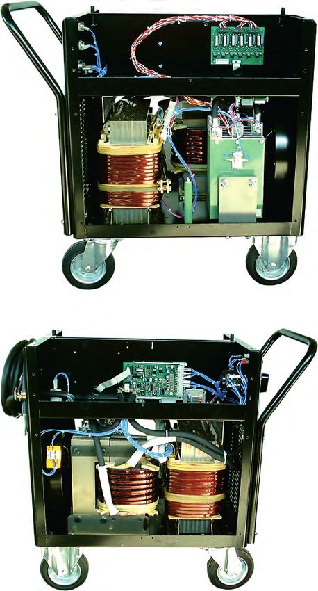
Tab. 7 Ersatzteile G450 S innen
Pos. Bezeichnung Art.-Nr.
A Treiberplatine SGR2 AN 600.005.003
Treiberplatine SGR2 AN Reparaturaustausch 600.005.003A
B Thyristorschutzplatine TSP1 600.100.007
C Thyristorsatz 450 A komplett 705.005.002
Thermoschalter 90° (Öffner) für Thyristorsatz 445.080.004
D Grundlast-Widerstand 82 Ohm 452.082.015
E Bockrolle Ø 140 mm 301.140.004
F Steuerplatine SGR1-2 / 400 A / 50 Hz 600.005.001
Steuerplatine im Reparaturaustausch 600.005.001A
Steuerplatine SGR1-2 / 400 A / 60 Hz 600.005.006
Steuerplatine im Reparaturaustausch 600.005.006A
G Steuertrafo 11 VA 462.018.024
H Entstörfilter 705.024.005
I Drossel G450 S komplett mit Anschlusskabel 706.005.002
J Ventilator A4E 300 450.300.006
K Kondensator 1 µF / 450 V für Ventilator 453.450.002
L Netzkabel komplett 4 × 6 qmm, 5 m, 32 A Stecker 704.060.029
M Lenkrolle Ø 140 mm 301.140.003
N Schweißtrafo G450 S komplett mit Anschlusskabel 706.005.001
Thermoschalter 170 °C (Öffner) für Schweißtrafo 445.170.002
O Gehäuse Handgriffbügel 715.055.010
BA-0003 • 2020-12-01 DE - 199 Anhang G450 S | G600 S
9.1.2 Ersatzteilliste G600 S
Abb. 10 Frontansicht G600 S
J
A
I B
C
H
G D
E
F
Tab. 8 Ersatzteile G600 S außen
Pos. Bezeichnung Art.-Nr.
A Haube G600 S 715.022.021
B Seitenblech rechts 715.022.020
C Drehschalter 2-polig, CK 1030 440.062.045
D Messgerät DAVM3 komplett 895.000.016
E Gerätesteckdose, 10-polig mit Schraubverschluss 410.010.044
Stecker, gerade, 10-polig mit Schraubverschluss 410.010.045
F Einbausteckbuchse BE 70-95 DIX BE 70-95
G Poti-Drehknopf Ø 36 mm 711.036.005
H Schaltergriff für Hauptschalter 440.220.051
I Seitenblech linke 715.022.019
J Lastöse D582 M12 V
DE - 20 BA-0003 • 2020-12-01G450 S | G600 S 9 Anhang
Abb. 11 Seitenansicht G600 S
L A
K
J
I
B
C
H
G
F
E
D
BA-0003 • 2020-12-01 DE - 219 Anhang G450 S | G600 S
Tab. 9 Ersatzteile G600 S innen
Pos. Bezeichnung Art.-Nr.
A Hauptschalter S440-645867 440.440.017
B Schweißtrafo G600 S, komplett mit Anschlusskabel 706.005.108
Thermoschalter 170 °C (Öffner) für Schweißtrafo 445.170.002
C Lenkrolle Ø 200 mm 301.200.016
D Drossel G600 S komplett mit Anschlusskabel 706.005.109
E Steuerplatine SGR1-2 / 600 A / 50 Hz 600.005.008
Steuerplatine SGR1-2 im Reparaturaustausch 600.005.008A
F Treiberplatine SGR1 AN 600.005.003
Treiberplatine SGR1 AN im Reparaturaustausch 600.005.003A
G Handgriffbügel 715.022.011
H Bockrolle Ø 200 mm 301.200.017
I Ventilator A4E 350, 230 V 450.350.007
Kondensator 5 µF für Ventilator 453.400.013
J Netzkabel komplett 4 × 10 qmm, 5 m 704.100.005
K Grundlast-Widerstand 82 Ohm 452.082.015
L Thyristorsatz 600 A 460.600.001
Thermoschalter 90° (Öffner) für Thyristorsatz 445.080.004
DE - 22 BA-0003 • 2020-12-01G450 S | G600 S 10 Schaltpläne 10 Schaltpläne 10.1 Schaltplan G450 S Abb. 12 Schaltplan G450 S BA-0003 • 2020-12-01 DE - 23
10 Schaltpläne                    G450 S | G600 S

10.2 Schaltplan G600 S

Abb. 13    Schaltplan G600 S

DE - 24                        BA-0003 • 2020-12-01
G450 S | G600 S        Notizen

Notizen

BA-0003 • 2020-12-01    DE - 25
EN                                                                                                                G450 S | G600 S

 Translation of the original operating instructions
 The manufacturer reserves the right, at any time and without prior notice, to make such changes and amendments to these operating
 instructions which may become necessary due to misprints, inaccuracies or improvements to the product. Such changes will, however,
 be incorporated into subsequent editions of the operating instructions. All brand names and trademarks that appear in these operating
 instructions are the property of their respective owners/manufacturers. The contact details for Jäckle & Ess System GmbH national
 subsidiaries and partners worldwide are provided on our website at www.jess-welding.com.

1        Identification                                  EN-3          5       Functional description for the G450 S
1.1      Marking                                         EN-3                  and G600 S                                       EN-10

2        Safety                                          EN-3          6       Putting into operation                           EN-10
2.1      Designated use                                  EN-3          6.1     Mains port                                       EN-12
2.2      Responsibilities of the user                    EN-3          6.2     Connecting welding cables                        EN-12
2.3      Personal protective equipment                   EN-3          6.3     Welding                                          EN-12
2.4      Disposal of the machine                         EN-3
2.5      Classification of the warnings                  EN-4          7       Operation                                        EN-13
2.6      Product safety                                  EN-4          7.1     Control elements                                 EN-13
2.7      Warning and information signs                   EN-5          7.1.1   G450 S control elements                          EN-13
2.8      Emergency information                           EN-5          7.1.2   G600 S control elements                          EN-14

3        Product description                             EN-6          8       Maintenance and cleaning                         EN-15
3.1      Technical data                                  EN-6
3.1.1    G450 S                                          EN-6          9       Appendix                                         EN-16
3.1.2    G600 S                                          EN-7          9.1     Spare parts list for the G450 S and G600 S       EN-16
3.1.3    Ambient conditions                              EN-7          9.1.1   Spare parts list for the G450 S                  EN-16
3.2      Nameplate                                       EN-8          9.1.2   Spare parts list for the G600 S                  EN-19
3.2.1    G450 S nameplate                                EN-8
3.2.2    G600 S nameplate                                EN-8          10      Circuit diagrams                                 EN-22
3.3      Signs and symbols used                          EN-9          10.1    G450 S circuit diagram                           EN-22
                                                                       10.2    G600 S circuit diagram                           EN-23
4        Scope of delivery                               EN-9
4.1      Transport                                       EN-9
4.2      Storage                                         EN-9

EN - 1                                                                                                        BA-0003 • 2020-12-01
G450 S | G600 S 1 Identification
1 Identification
The welding rectifiers G450 S and G600 S are designed exclusively for electrode welding, gouging and
TIG welding in lift-arc mode (without HF) with direct current.
1.1 Marking
This product fulfils the requirements that apply to the market to which it has been introduced.
A corresponding marking has been affixed to the product, if required.
2 Safety
Please observe the attached “Safety instructions”.
2.1 Designated use
The device described in these instructions may be used only for the purpose and in the manner described in
these instructions. In doing so, observe the operating, maintenance and servicing conditions.
• Any other use is considered improper.
• Unauthorised modifications or changes to enhance the performance are not permitted.
2.2 Responsibilities of the user
Only the following personnel may work on the device:
• those who are familiar with the basic regulations on occupational safety and accident prevention;
• those who have been instructed on how to handle the device;
• those who have read and understood these operating instructions;
• those who have read and understood the attached “Safety instructions” document;
• those who have been trained accordingly;
• those who are able to recognize possible risks because of their special training, knowledge, and
experience.
Keep other people out of the work area.
Please observe the occupational health and safety regulations of the relevant country.
• Observe the regulations on occupational safety and accident prevention. According to
DIN EN 60974-10, this device is considered class A welding equipment. Class A welding equipment is
not intended for use in residential areas with a public low-voltage power supply system. Such use can
cause electromagnetic interferences that may result in equipment damage and malfunctions. Only use
the device in industrial areas.
2.3 Personal protective equipment
To prevent danger to the user, these instructions recommend the use of personal protective
equipment (PPE).
This consists of protective clothing, safety goggles, a class P3 respiratory mask, protective gloves and
safety shoes.
2.4 Disposal of the machine
Do not dispose of waste electrical equipment in the normal household waste! Under consideration of the
EC Directive on Waste Electrical and Electronic Equipment and its implementation according to national law,
electrical equipment that has reached the end of its service life must be separately collected and passed to
an appropriate, environmentally responsible recycling centre. According to the instructions of the municipal
authorities, the owner of the equipment is obliged to pass any units placed out of operation to a regional
collection centre. Further information can be found online by searching for “WEEE”.
BA-0003 • 2020-12-01 EN - 32 Safety G450 S | G600 S
2.5 Classification of the warnings
The warnings used in the operating instructions are divided into four different categories and are indicated
prior to potentially dangerous work steps. Arranged in descending order of importance, they have the
following meanings:
DANGER
Describes an imminent threatening danger. If not avoided, this will result in fatal or extremely critical
injuries.
WARNING
Describes a potentially dangerous situation. If not avoided, this may result in serious injuries.
CAUTION
Describes a potentially harmful situation. If not avoided, this may result in slight or minor injuries.
NOTICE
Describes the risk of impairing work results or potential material damage to the equipment.
2.6 Product safety
The product has been developed and manufactured in accordance with state-of-the-art technology and the
recognized safety standards and regulations. These operating instructions warn you against unavoidable
residual risks to users, third parties, devices or other material property. Disregarding these warnings may
result in risks to human life and health, environmental damage or material damage.
• The product may only be operated in an unmodified, technically perfect condition, within the limits
described in these instructions.
• Always observe the limit values specified in the technical data. Overloads lead to destruction.
• Safety features on the device must never be disassembled, bridged or otherwise bypassed.
• During welding work outdoors, use suitable protection against the weather conditions.
• Check the electrical device for any damage and for proper functioning in accordance with its
designated use.
• Never expose the electrical device to rain and avoid damp or wet environments.
• Protect yourself from electrical accidents by using insulating mats and wearing dry clothing.
• Never use the electrical device in areas subject to a risk of fire or explosion.
• Arc welding may cause damage to the eyes, skin and hearing. When working with the device, always
wear the prescribed protective equipment.
• Metal vapours, especially from lead, cadmium, copper and beryllium, are all harmful to health! Ensure
sufficient ventilation or extraction. Always ensure compliance with the legal limit values.
• Rinse workpieces that have been degreased with chlorinated solvents using clean water to prevent the
risk of phosgene gas formation. Do not place degreasing baths containing chlorine in the vicinity of
the welding area.
• Adhere to the general fire protection regulations and remove flammable materials from the vicinity of
the welding work area prior to starting work. Keep suitable fire extinguishing equipment at the
workplace ready for use.
EN - 4 BA-0003 • 2020-12-01G450 S | G600 S 2 Safety
2.7 Warning and information signs
The following warning and information signs can be found on the product:
Symbol Meaning
Read and observe the operating instructions!
Disconnect the mains plug before opening!
Warning against hot surfaces.
2.8 Emergency information
In the event of an emergency, immediately disconnect the following supplies:
• Electrical power supply
• Compressed air supply
• Gas supply
Further measures can be found in the operating instructions for the power source or the documentation for
other peripheral devices.
BA-0003 • 2020-12-01 EN - 53 Product description G450 S | G600 S
3 Product description
3.1 Technical data
3.1.1 G450 S
Fig. 1 G450 S
Tab. 1 G450 S technical data
Power source G450 S
Mains voltage, 3 phases 400 V, 50/60 Hz
Fuse 63 A time-lag
Max. power consumption 39 kVA
Setting range 20–450 A, continuous
Operating voltage 21–38 V
Idle voltage 90 V
Duty cycle 60 % 450 A/38 V
Duty cycle 100 % 320 A/33 V
Protection type IP22
Insulation class H (180°C)
Type of cooling F
Weight 145 kg
Dimensions L × W × H 600 × 430 × 710
• Manufactured in accordance with the European standards EN 60974-1 and EN 60974-10
EN - 6 BA-0003 • 2020-12-01G450 S | G600 S 3 Product description
3.1.2 G600 S
Fig. 2 G600 S
Tab. 2 G600 S technical data
Power source G600 S
Mains voltage, 3 phases 400 V, 50/60 Hz
Fuse 63 A time-lag
Max. power consumption 50 kVA
Setting range 35–600 A, continuous
Operating voltage 21–44 V
Idle voltage 80 V
Duty cycle 35 % 600 A/44 V
Duty cycle 100 % 350 A/34 V
Protection type IP22
Insulation class H (180°C)
Type of cooling F
Weight 210 kg
Dimensions L × W × H 810 × 500 × 850
• Manufactured in accordance with the European standards EN 60974-1 and EN 60974-10
3.1.3 Ambient conditions
The welding power source must only be operated at a temperature between −10°C and +40°C and at
a relative air humidity of up to 50 % at +40°C or up to 90 % at +20°C. The ambient air must be free
of unusually high quantities of dust, acids, corrosive gases or substances etc., other than those that arise
during the welding process.
BA-0003 • 2020-12-01 EN - 73 Product description G450 S | G600 S
3.2 Nameplate
3.2.1 G450 S nameplate
The welding power source is labelled with a nameplate on the housing as follows:
Fig. 3 G450 S nameplate
3.2.2 G600 S nameplate
The welding power source is labelled with a nameplate on the housing as follows:
Fig. 4 G600 S nameplate
EN - 8 BA-0003 • 2020-12-01G450 S | G600 S 4 Scope of delivery
3.3 Signs and symbols used
Symbol Description
• Bullet symbol for instructions and lists
Cross reference symbol refers to detailed, supplementary or further information
1. Step(s) described in the text to be carried out in succession
4 Scope of delivery
Tab. 3 Scope of delivery
• Welding power source • Operating instructions • “General safety information”
instruction leaflet
Order the equipment parts and wear parts separately.
The order data and ID numbers for the equipment parts and wear parts can be found in the current product
catalogue.
Contact details for advice and orders can be found online at www.jaeckleess.com.
4.1 Transport
Although the items delivered are carefully checked and packaged, it is not possible to fully exclude the risk
of transport damage.
Goods-in inspection Use the delivery note to check that everything has been delivered.
Check the delivery for damage (visual inspection).
In case of complaints If the delivery has been damaged during transportation, contact the last
carrier immediately. Retain the packaging for potential inspection by the
carrier.
Packaging for returns Where possible, use the original packaging and the original packaging
material. If you have any questions concerning the packaging and/or how
to secure an item during shipment, please consult your supplier.
4.2 Storage
Physical storage conditions in a closed environment:
See 3.1.3 Ambient conditions on page EN-7
BA-0003 • 2020-12-01 EN - 95 Functional description for the G450 S and G600 S G450 S | G600 S
5 Functional description for the G450 S and G600 S
Fig. 5 Functional description for the G450 S and G600 S
A “Hot start” rotary switch C Remote control socket E Welding cable connection bush (+) G Welding current knob
B Internal/external rotary D Welding cable connection bush (−) F Digital welding current indicator H Main switch
switch
A
H B
G
F
C
E D
6 Putting into operation
DANGER
Risk of injury due to unexpected start
The following instructions must be adhered to during all maintenance, servicing, assembly, disassembly
and repair work:
• Switch off the power source.
• Disconnect all electrical connections.
• Switch off the entire welding system.
CAUTION
Risk of injury
Increased noise pollution.
• Wear personal protective equipment: ear protectors.
EN - 10 BA-0003 • 2020-12-01G450 S | G600 S 6 Putting into operation
WARNING
Electric shock
Dangerous voltage due to defective cables.
• Check all live cables and connections for proper installation and damage.
• Replace any damaged, deformed or worn parts.
WARNING
Risk of injury
Feet may be crushed due to sudden rolling movement of the power source.
• Inspect the safety of the machine.
• Position on flat, even surfaces only.
CAUTION
Risk of injury
Heavy weight.
• Ensure that you slow down in good time when moving the device.
NOTICE
• Note the following instructions:
See 3 Product description on page EN-6
• Only qualified personnel are permitted to perform work on the device or system.
• Components must only be used in environments with sufficient ventilation.
When setting up the machine, ensure that you leave sufficient space for the entry and exit of cooling air
so that the specified duty cycle can be completed. Do not use the machine outdoors during rain.
NOTICE
Do not expose the machine to moisture, weld spatter or directly to sparks during welding.
BA-0003 • 2020-12-01 EN - 116 Putting into operation G450 S | G600 S
6.1 Mains port
DANGER
Electric shock
Dangerous voltage due to defective cables.
• Check all live cables and connections for proper installation and damage.
• Replace any damaged, deformed or worn parts.
DANGER
Personal injuries and material damage
Incorrect mains connection can result in personal injuries and material damage.
• Do not mount the components until the mains plug is disconnected.
• Connect the system only to the sockets which have protective earthing conductor.
• Only qualified personnel are permitted to perform work on the device or system.
1 Insert the mains plug into the corresponding socket.
6.2 Connecting welding cables
Insert the plugs for the electrode and workpiece cables into the welding cable connection bushes and hand-
tighten by twisting clockwise. Take care to use the correct connection polarities for the electrodes used.
Attach the workpiece clamp to the workpiece so as to enable good conductivity, i.e. not on paint, rust or
similar.
NOTICE
Good contact must be ensured in relation to all connections in the welding current circuit, such as the
workpiece connection and welding cable connection. Poor contact results in a high transition resistance,
which in turn causes the system to heat up and results in poor welding properties.
6.3 Welding
Select the electrodes on the basis of the welding task and workpiece to be welded and clamp into the
electrode holder. Set the desired welding current.
EN - 12 BA-0003 • 2020-12-01G450 S | G600 S 7 Operation
7 Operation
NOTICE
• Only qualified personnel are permitted to perform work on the device or system.
7.1 Control elements
7.1.1 G450 S control elements
Fig. 6 G450 S control elements
A “Hot start” rotary switch E Welding cable connection bush (−) I Temperature fault light
B Internal/external rotary switch F Welding cable connection bush (+) J Mains indicator light
C Remote control socket G Welding current knob K Fine-wire fuse
D Digital welding current indicator H Main switch
K
A
J
I
H
B
G
C
D
F E
Tab. 4 G450 S control elements
Pos. Description
A Hot start on/off rotary switch. For switching the hot start function on or off.
B Internal/external rotary switch. For switching between the internal and external operating modes (remote control).
C 10-pole remote control socket. For connecting a foot or hand-operated remote control. See the circuit diagram for
connection.
D Digital welding current indicator. The welding current value is displayed during the welding process and for about
5 seconds after this ends.
E Welding cable connection bush (−)
F Welding cable connection bush (+)
G Welding current knob. Continuous adjustment of the welding current between 20 A and 450 A.
H Main switch Position “0”: machine off. Position “I”: machine on. The mains indicator light illuminates. The fan
is running.
I Temperature fault light. Illuminates if the welding transformer or thyristor set overheats. The arc can no longer be
started. If the fan is running, the machine will ready for operation again after approximately 5 minutes.
J Mains indicator light. Illuminates when the machine is switched on.
K Fine-wire fuse F1. 2 A time-lag for control transformer.
BA-0003 • 2020-12-01 EN - 137 Operation G450 S | G600 S
7.1.2 G600 S control elements
Fig. 7 G600 S control elements
A Internal/external rotary switch D Welding cable connection bush (+) G Mains indicator light
B Digital voltmeter/ammeter E Welding cable connection bush (−) H Main switch
C Remote control socket F Fine-wire fuse I Temperature fault light
J Welding current knob
J
A
I
H
B
G
F C
E D
Tab. 5 G600 S control elements
Pos. Description
A Internal/external rotary switch. For switching between the internal and external operating modes
(remote control).
B Digital voltmeter/ammeter. Indicates the present current and voltage. At the end of the welding process, the
final values remain on the display for about 15 seconds.
C 10-pole remote control socket. For connecting a foot or hand-operated remote control. See the circuit diagram
for connection.
D Welding cable connection bush (+)
E Welding cable connection bush (−)
F Fine-wire fuse F1. 2 A time-lag for control transformer.
G Mains indicator light. Illuminates when the machine is switched on.
H Main switch Position “0”: machine off. Position “I”: machine on. The mains indicator light illuminates. The fan is
running.
I Temperature fault light. Illuminates if the welding transformer or thyristor set overheats. The arc can no longer
be started. If the fan is running, the machine will ready for operation again after approximately 5 minutes.
J Welding current knob. Continuous adjustment of the welding current between 35 A and 600 A.
EN - 14 BA-0003 • 2020-12-01G450 S | G600 S 8 Maintenance and cleaning
8 Maintenance and cleaning
NOTICE
The maintenance intervals are standard values and refer to single-shift operation.
When using arc welding equipment, always observe the provisions of EN 60974-4 Inspection and testing,
as well as any national laws and regulations.
DANGER
Electric shock
The following instructions must be adhered to during all maintenance, servicing, assembly, disassembly
and repair work:
• Switch off the power source.
• Disconnect all electrical connections.
• Switch off the entire welding system.
The welding power source is virtually maintenance-free.
However, Jäckle & Ess Systems GmbH recommends the following maintenance tasks:
• Clean the contact tip and gas nozzle regularly to remove weld spatter and dirt. Apply anti-spatter
agent to nozzles after cleaning to reduce spatter adhesion.
• Check the contact tip regularly for wear and damage and replace it in good time.
• Depending on the level of dirt present, air-blast the system with compressed air.
Overheating
If extended use and very hot ambient conditions lead to the machine overheating, it will be switched off and
welding can no longer continue until it has cooled down again.
Should this occur, text such as the following will appear on the control panel’s display:
• t°C - 03 - hot
t°C = hot = temperature too high
BA-0003 • 2020-12-01 EN - 159 Appendix G450 S | G600 S
9 Appendix
9.1 Spare parts list for the G450 S and G600 S
9.1.1 Spare parts list for the G450 S
Fig. 8 Front view of G450 S
A
B
L
K
C
J D
I
H E
F
G
Tab. 6 External spare parts for G450 S
Pos. Name Item no.
A Hoisting eye D582 M12 V
B Housing hood for G450 S 715.005.012
C Side panel 715.005.013
D Front panel for G450 S 304.005.012
E Knob Ø 15 mm 711.015.006
F Female connector, 10-pole with screw fastening 410.010.044
Plug, straight, 10-pole (cable) 410.010.045
Protective cap 310.350.050
G Built-in socket BEB 35-50 422.031.024
H Built-in socket BEB 35-50 422.031.024
I LED display board STROMANZ, complete with frame 600.005.002
LED display board as repair replacement 600.005.002A
J Knob Ø 36 mm 711.036.005
K Main switch S 225-647904 440.225.102
L Fuse holder with bayonet lock cap 464.601.001
Fine-wire fuse 5 × 20 mm T2A 464.020.014
EN - 16 BA-0003 • 2020-12-01G450 S | G600 S 9 Appendix
Fig. 9 Side view of G450 S
A
O
B
C
N
D
M E
L
F
G
K H
J
I
BA-0003 • 2020-12-01 EN - 179 Appendix G450 S | G600 S
Tab. 7 Internal spare parts for G450 S
Pos. Name Item no.
A Driver board SGR2 AN 600.005.003
Driver board SGR2 AN as repair replacement 600.005.003A
B Thyristor protection board TSP1 600.100.007
C Thyristor set 450 A complete 705.005.002
Thermal switch 90°C (normally closed switch) for thyristor set 445.080.004
D Base load resistor 82 ohms 452.082.015
E Fixed castor Ø 140 mm 301.140.004
F Control board SGR1-2 / 400 A / 50 Hz 600.005.001
Control board as repair replacement 600.005.001A
Control board SGR1-2 / 400 A / 60 Hz 600.005.006
Control board as repair replacement 600.005.006A
G Control transformer 11 VA 462.018.024
H Noise filter 705.024.005
I Throttle for G450 S complete with connection cable 706.005.002
J Fan A4E 300 450.300.006
K Capacitor 1 µF / 450 V for fan 453.450.002
L Complete mains cable 4 × 6 mm2, 5 m, 32 A plug 704.060.029
M Steering castor Ø 140 mm 301.140.003
N Welding transformer for G450 S complete with connection 706.005.001
cable
Thermal switch 170°C (normally closed switch) for welding 445.170.002
transformer
O Housing handlebar 715.055.010
EN - 18 BA-0003 • 2020-12-01G450 S | G600 S 9 Appendix
9.1.2 Spare parts list for the G600 S
Fig. 10 Front view of G600 S
J
A
I B
C
H
G D
E
F
Tab. 8 External spare parts for G600 S
Pos. Name Item no.
A Hood for G600 S 715.022.021
B Right side panel 715.022.020
C Rotary switch, 2-pole, CK 1030 440.062.045
D Measuring instrument DAVM3 complete 895.000.016
E Female connector, 10-pole with screw fastening 410.010.044
Plug, straight, 10-pole with screw fastening 410.010.045
F Built-in socket BE 70-95 DIX BE 70-95
G Potentiometer knob Ø 36 mm 711.036.005
H Switch handle for main switch 440.220.051
I Left side panel 715.022.019
J Hoisting eye D582 M12 V
BA-0003 • 2020-12-01 EN - 199 Appendix G450 S | G600 S
Fig. 11 Side view of G600 S
L A
K
J
I
B
C
H
G
F
E
D
EN - 20 BA-0003 • 2020-12-01G450 S | G600 S 9 Appendix
Tab. 9 Internal spare parts for G600 S
Pos. Name Item no.
A Main switch S440-645867 440.440.017
B Welding transformer for G600 S complete with connection 706.005.108
cable
Thermal switch 170°C (normally closed switch) for welding 445.170.002
transformer
C Steering castor Ø 200 mm 301.200.016
D Throttle for G600 S complete with connection cable 706.005.109
E Control board SGR1-2 / 600 A / 50 Hz 600.005.008
Control board SGR1-2 as repair replacement 600.005.008A
F Driver board SGR1 AN 600.005.003
Driver board SGR1 AN as repair replacement 600.005.003A
G Handlebar 715.022.011
H Fixed castor Ø 200 mm 301.200.017
I Fan A4E 350, 230 V 450.350.007
Capacitor 5 µF for fan 453.400.013
J Complete mains cable 4 × 10 mm2, 5 m 704.100.005
K Base load resistor 82 ohms 452.082.015
L Thyristor set 600 A 460.600.001
Thermal switch 90°C (normally closed switch) for thyristor set 445.080.004
BA-0003 • 2020-12-01 EN - 2110 Circuit diagrams G450 S | G600 S 10 Circuit diagrams 10.1 G450 S circuit diagram Fig. 12 G450 S circuit diagram EN - 22 BA-0003 • 2020-12-01
G450 S | G600 S                     10 Circuit diagrams

10.2 G600 S circuit diagram

Fig. 13    G600 S circuit diagram

BA-0003 • 2020-12-01                            EN - 23
Jäckle & Ess System GmbH

                                                                  BA-0003 • 2020-12-01

                           Jäckle & Ess System GmbH
                           Riedweg 4 u. 9 • D–88339 Bad Waldsee
                           Tel.:     ++49 (0) 7524 9700–0
                           Fax:      ++49 (0) 7524 9700–30
                           Email: sales@jess-welding.com

                           www.jess-welding.com
Sie können auch lesen