Hybrid/Pegasus - Directions for use Gebrauchsanweisung Mode d'emploi Instrucciones de uso - Nilfisk Food
←
→
Transkription von Seiteninhalten
Wenn Ihr Browser die Seite nicht korrekt rendert, bitte, lesen Sie den Inhalt der Seite unten
Hybrid/Pegasus
Pegasus-BW4, Hybrid-BW4, Hybrid-BW7
Hybrid-BF4, Hybrid-BF8

Directions for use
Gebrauchsanweisung
Mode d’emploi
Instrucciones de uso
Declaration of Conformity

                 Pegasus-BW4, Hybrid-BW4, Hybrid-BW7
                                Hybrid-BF4, Hybrid-BF8

     Declaration of Conformity                Konformitätserklärung

     Déclaration de Conformité                Dichiarazione di Conformità

     Declaración de Conformidad               Declaração de Conformidade

     Δήλωση Συμμόρφωσης                       Overeenkomstigheidsverklaring

     Försäkran om överensstämmelse            Vaatimustenmukaisuusvakuutus

     Overensstemmelseserklæring               Deklaracja zgodności

     Декларация о соответствии                Megfelelőségi nyilatkozat

     Izjava o skladnosti                      Izjava o usklađenosti

     Deklaracija o konformitetu               Declaraţie de Conformitate

     Декларация за съответствие               Prohlášení o shodě

     Prehlásenie o konformite                 Uygunluk Bildirgesi

     Vastavusdeklaratsioon                    Atitikties deklaracija

     Paziņojums par atbilstību prasībām       Свідчення про відповідність вимогам

Nilfisk FOOD
Blytækkervej 2
9000 Aalborg
Danmark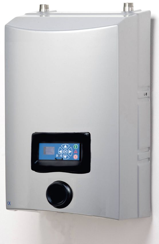
Declaration of Conformity                                               Konformitätserklärung
We Nilfisk FOOD, declare under our sole responsibility that the        We Nilfisk FOOD, declare under our sole responsibility that the
products MU, MD, HYBRID-BW, PEGASUS-BW, BF4, BF8. To                   products MU, MD, HYBRID-BW, PEGASUS-BW, BF4, BF8. To
which this declaration relates, are in conformity with these Council   which this declaration relates, are in conformity with these Council
directives on the approximation of the laws of the EC menber states:   directives on the approximation of the laws of the EC menber states:
Machinery Directive (2006/42/EC).                                      Maschinendirektive (2006/42/EG).
-        EN 60335-2-79 : 2012                                          -        EN 60335-2-79 : 2012
EMC Directive (2014/30/EU)                                             EMC Direktive (2014/30/EU)
-        EN 55014-1 : 2017                                             -        EN 55014-1 : 2017
-        EN 55014-2 : 2015                                             -        EN 55014-2 : 2015
-        EN 61000-3-2 : 2014                                           -        EN 61000-3-2 : 2014
-       EN 61000-3-3 : 2013.                                           -       EN 61000-3-3 : 2013.

       Déclaration de conformité                                              Dichiarazione di conformità
Nous, Nilfisk FOOD, déclarons sous notre seule responsabilité,         Nilfisk FOOD dichiara sotto la sua esclusiva responsabilità che i
que les produits MU, MD, HYBRID-BW, PEGASUS-BW, BF4, BF8,              prodotti MU, MD, HYBRID-BW, PEGASUS-BW, BF4, BF8, ai quali si
auxquels se réfère cette déclaration, sont conformes aux Directives    riferisce questa dichiarazione, sono conformi alle seguenti direttive
du Conseil concernant le rapprochement des législations des Etats      del Consiglio riguardanti il riavvicinamento delle legislazioni degli
membres CE relatives aux normes énoncées ci¬dessous :                  Stati membri CE:
Directive Machines (2006/42/CE).                                       Direttiva Macchine (2006/42/CE).
-       EN 60335-2-79 : 2012                                           -        EN 60335-2-79 : 2012
Directive Compatibilité Electromagnétique CEM (2014/30/EU)             Direttiva EMC (2014/30/EU)
-       EN 55014-1 : 2017                                              -        EN 55014-1 : 2017
-       EN 55014-2 : 2015                                              -        EN 55014-2 : 2015
-       EN 61000-3-2 : 2014                                            -        EN 61000-3-2 : 2014
-       EN 61000-3-3 : 2013.                                           -        EN 61000-3-3 : 2013.

       Declaración de conformidad                                             Declaração de Conformidade
Nosotros, Nilfisk FOOD, declaramos bajo nuestra entera responsa-       A Nilfisk FOOD declara sob sua única responsabilidade que os
bilidad que los productos MU, MD, HYBRID-BW, PEGASUS-BW,               produtos MU, MD, HYBRID-BW, PEGASUS-BW, BF4, BF8, aos
BF4, BF8, a los cuales se refiere esta declaración, están conformes    quais diz respeito esta declaração, estão em conformidade com as
con las Directivas del Consejo en la aproximación de las leyes de      seguintes Directivas do Conselho sobre a aproximação das legisla-
las Estados Miembros del EM:                                           ções dos Estados Membros da CE:
Directiva de Maquinaria (2006/42/CE).                                  Directiva Máquinas (2006/42/CE).
-        EN 60335-2-79 : 2012                                          -        EN 60335-2-79 : 2012
Directiva EMC (2014/30/EU)                                             Directiva EMC (2014/30/EU)
-        EN 55014-1 : 2017                                             -        EN 55014-1 : 2017
-        EN 55014-2 : 2015                                             -        EN 55014-2 : 2015
-        EN 61000-3-2 : 2014                                           -        EN 61000-3-2 : 2014
-        EN 61000-3-3 : 2013.                                          -       EN 61000-3-3 : 2013

       Δήλωση συμμόρφωσης                                                     Verklaring van overeenstemming
Εμείς, η Nilfisk FOOD, δηλώνουμε με αποκλειστικά δική μας ευθύνη       Wij, Nilfisk FOOD, verklaren geheel onder eigen verantwoordelijk-
ότι τα προϊόντα MU, MD, HYBRID-BW, PEGASUS-BW, BF4, BF-                heid dat de producten MU, MD, HYBRID-BW, PEGASUS-BW, BF4,
8στα οποία αναφέρεται η παρούσα δήλωση, συμμορφώνονται με              BF8 waarop deze verklaring betrekking heeft, in overeenstemming
τις εξής Οδηγίες του Συμβουλίου περί προσέγγισης των νομοθεσι-         zijn met de Richtlijnen van de Raad in zake de onderlinge aanpas-
ών των κρατών μελών της ΕΕ:                                            sing van de wetgeving van de EG Lidstaten betreffende:
Οδηγία για μηχανήματα (2006/42/EK).                                    Machine Richtlijn (2006/42/EG).
-        EN 60335-2-79 : 2012                                          -        EN 60335-2-79 : 2012
Οδηγία Ηλεκτρομαγνητικής Συμβατότητας (EMC) (2014/30/EU).              EMC Richtlijn (2014/30/EU).
-        EN 55014-1 : 2017                                             -        EN 55014-1 : 2017
-        EN 55014-2 : 2015                                             -        EN 55014-2 : 2015
-        EN 61000-3-2 : 2014                                           -        EN 61000-3-2 : 2014
-       EN 61000-3-3 : 2013.                                           -        EN 61000-3-3 : 2013.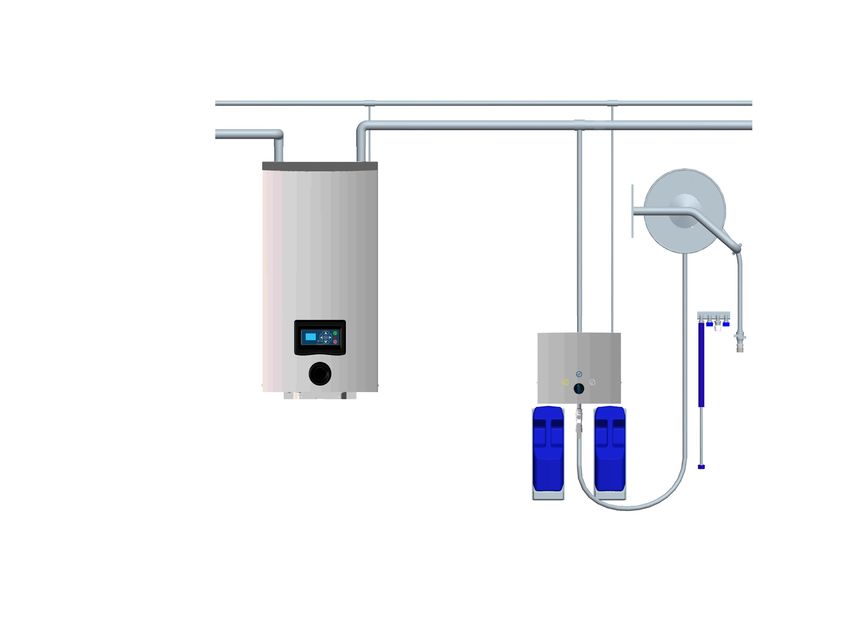
Försäkran om överensstämmelse                                           Vaatimustenmukaisuusvakuutus
Vi, Nilfisk FOOD, försäkrar under ansvar att produkterna MU, MD,        Me, Nilfisk FOOD, vakuutamme omalla vastuullamme, että tuotteet
HYBRID-BW, PEGASUS-BW, BF4, BF8, som omfattas av denna                  MU, MD, HYBRID-BW, PEGASUS-BW, BF4, BF8, joita tämä vakuu-
försäkran, är i överensstämmelse med rådets direktiv om inbördes        tus koskee, ovat EY:n jäsenvaltioiden lainsäädännön yhdenmuka-
närmande till EU-medlemsstaternas lagstiftning, avseende:               istamiseen tähtäävien Euroopan neuvoston direktiivien vaatimusten
Maskindirektivet (2006/42/EG).                                          mukaisia seuraavasti:
-         EN 60335-2-79 : 2012                                          Konedirektiivi (2006/42/EY).
EMC-direktivet (2014/30/EU).                                            -       EN 60335-2-79 : 2012
-         EN 55014-1 : 2017                                             EMC-direktiivi (2014/30/EU).
-         EN 55014-2 : 2015                                             -       EN 55014-1 : 2017
-         EN 61000-3-2 : 2014                                           -       EN 55014-2 : 2015
-        EN 61000-3-3 : 2013.                                           -       EN 61000-3-2 : 2014
                                                                        -       EN 61000-3-3 : 2013.

       Overensstemmelseserklæring                                              Deklaracja zgodności
Vi, Nilfisk FOOD, erklærer under ansvar at produkterne MU, MD,          My, Nilfisk FOOD, oświadczamy z pełną odpowiedzialnością, że
HYBRID-BW, PEGASUS-BW, BF4, BF8som denne erklæring om-                  nasze wyroby MU, MD, HYBRID-BW, PEGASUS-BW, BF4, BF8,
handler, er i overensstemmelse med disse af Rådets direktiver om        których deklaracja niniejsza dotyczy, są zgodne z następującymi
indbyrdes tilnærmelse til EF-medlemsstaternes lovgivning:               wytycznymi Rady d/s ujednolicenia przepisów prawnych krajów
Maskindirektivet (2006/42/EF).                                          członkowskich WE:
-         EN 60335-2-79 : 2012                                          Dyrektywa Maszynowa (2006/42/WE).
EMC-direktivet (2014/30/EU).                                            -        EN 60335-2-79 : 2012
-         EN 55014-1 : 2017                                             Dyrektywa EMC (2014/30/EU).
-         EN 55014-2 : 2015                                             -        EN 55014-1 : 2017
-         EN 61000-3-2 : 2014                                           -        EN 55014-2 : 2015
-        EN 61000-3-3 : 2013.                                           -        EN 61000-3-2 : 2014
                                                                        -       EN 61000-3-3 : 2013.

        Декларация соответствия
Мы, компания Nilfisk FOOD, со всей ответственностью заявля-                    Megfelelőségi nyilatkozat
ем, что изделия MU, MD, HYBRID-BW, PEGASUS-BW, BF4, BF8,                Mi, Nilfisk FOOD, izjavljujemo pod vlastitom odgovornošću da je
к которым относится настоящая декларация, соответствуют                 proizvod MU, MD, HYBRID-BW, PEGASUS-BW, BF4, BF8, na
следующим Директивам Совета Евросоюза об унификации                     koji se ova izjava odnosi, u skladu s direktivama ovog Vijeća o
законодательных предписаний стран-членов ЕС:                            usklađivanju zakona država članica EU:
Механические устройства (2006/42/EC).                                   Direktiva za strojeve (2006/42/EK).
-       EN 60335-2-79 : 2012                                            -        EN 60335-2-79 : 2012
Электромагнитная совместимость (2014/30/EU)                             Direktiva za elektromagnetsku kompatibilnost (2014/30/EU).
-       EN 55014-1 : 2017                                               -        EN 55014-1 : 2017
-       EN 55014-2 : 2015                                               -        EN 55014-2 : 2015
-       EN 61000-3-2 : 2014                                             -        EN 61000-3-2 : 2014
-       EN 61000-3-3 : 2013.                                            -        EN 61000-3-3 : 2013.

        Izjava o skladnosti                                                    Izjava o usklađenosti
V Nilfisk FOODu s polno odgovornostjo izjavljamo, da so naši izdelki    Mi, Nilfisk FOOD, izjavljujemo pod vlastitom odgovornošću da je
MU, MD, HYBRID-BW, PEGASUS-BW, BF4, BF8na katere se ta iz-              proizvod MU, MD, HYBRID-BW, PEGASUS-BW, BF4, BF8, na koji
java nanaša, v skladu z naslednjimi direktivami Sveta o približevanju   se ova izjava odnosi, u skladu s direktivama ovog Vijeća o usklađi-
zakonodaje za izenačevanje pravnih predpisov držav članic ES:           vanju zakona država članica EU:
Direktiva o strojih (2006/42/ES).                                       Direktiva za strojeve (2006/42/EZ).
-        EN 60335-2-79 : 2012                                           -        EN 60335-2-79 : 2012
Direktiva o elektromagnetni združljivosti (EMC) (2014/30/EU).           Direktiva za elektromagnetsku kompatibilnost (2014/30/EU).
-        EN 55014-1 : 2017                                              -        EN 55014-1 : 2007
-        EN 55014-2 : 2015                                              -        EN 55014-2 : 2015
-        EN 61000-3-2 : 2014                                            -        EN 61000-3-2 : 2014
-        EN 61000-3-3 : 2013.                                           -        EN 61000-3-3 : 2013.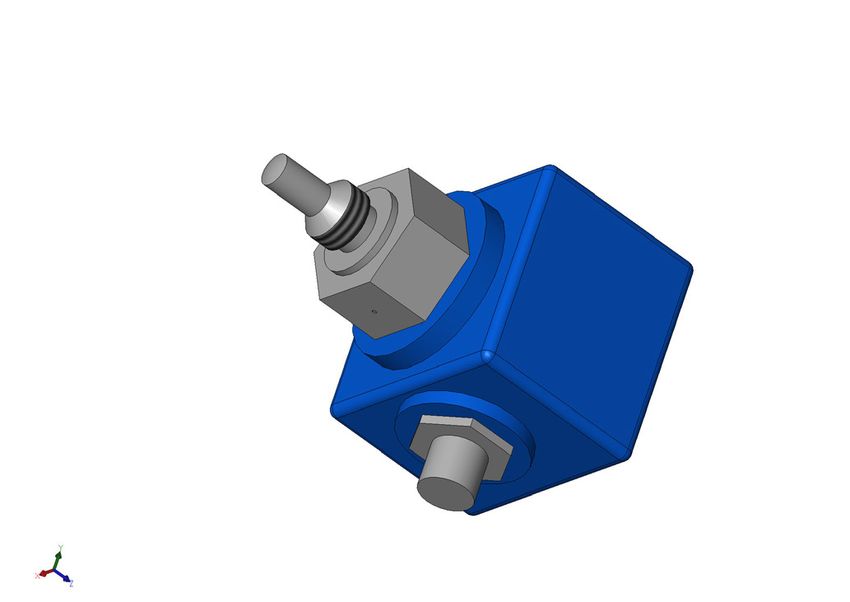
Deklaracija o konformitetu                                                   Declaraţie de conformitate
Mi, Nilfisk FOOD, izjavljujemo pod vlastitom odgovornošću da                 Noi, Nilfisk FOOD, declarăm pe propria răspundere că produsele
je proizvod MU, MD, HYBRID-BW, PEGASUS-BW, BF4, BF8                          MU, MD, HYBRID-BW, PEGASUS-BW, BF4, BF8la care se referă
na koji se ova izjava odnosi, u skladu sa direktivama, Saveta za             această declaraţie, sunt în conformitate cu aceste Directive de Con-
usklađivanje zakona država članica EU:                                       siliu asupra armonizării legilor Statelor Membre CE:
Direktiva za mašine (2006/42/EC).                                            Directiva Utilaje (2006/42/CE).
-        EN 60335-2-79 : 2012                                                -        EN 60335-2-79 : 2012
EMC direktiva (2014/30/EU).                                                  Directiva EMC (2014/30/EU)
-        EN 55014-1 : 2017                                                   -        EN 55014-1 : 2017
-        EN 55014-2 : 2015                                                   -        EN 55014-2 : 2015
-        EN 61000-3-2 : 2014                                                 -        EN 61000-3-2 : 2014
-        EN 61000-3-3 : 2013.                                                -        EN 61000-3-3 : 2013.

        Декларация за съответствие                                                   Prohlášení o shodě
Ние, фирма Nilfisk FOOD, заявяваме с пълна отговорност, че                   My firma Nilfisk FOOD prohlašujeme na svou plnou odpovědnost, že
продуктите MU, MD, HYBRID-BW, PEGASUS-BW, BF4, BF8, за                       výrobky MU, MD, HYBRID-BW, PEGASUS-BW, BF4, BF8, na něž
които се отнася настоящата декларация, отговарят на следни-                  se toto prohlášení vztahuje, jsou v souladu s ustanoveními směrnice
те указания на Съвета за уеднаквяване на правните разпоред-                  Rady pro sblížení právních předpisůčlenských států Evropského
би на държавите членки на ЕС:                                                společenství v oblastech:
Директива за машините (2006/42/EO).                                          Směrnice pro strojní zařízení (2006/42/ES).
-      EN 60335-2-79 : 2012                                                  -       EN 60335-2-79 : 2012
Директива за електромагнитна съвместимост (2014/30/ EU).                     Směrnice pro elektromagnetickou kompatibilitu (EMC) (2014/30/EU)
-      EN 55014-1 : 2017                                                     -       EN 55014-1 : 2017
-      EN 55014-2 : 2015                                                     -       EN 55014-2 : 2015
-      EN 61000-3-2 : 2014                                                   -       EN 61000-3-2 : 2014
-      EN 61000-3-3 : 2013.                                                  -       EN 61000-3-3 : 2013.

        Prehlásenie o zhode                                                         Uygunluk Beyanı
My firma Nilfisk FOOD prehlasujeme na svoju plnú zodpovednost’,              Nilfisk FOOD olarak bu beyannameye konu olan MU, MD, HYB-
že výrobky MU, MD, HYBRID-BW, PEGASUS-BW, BF4, BF8, na                       RID-BW, PEGASUS-BW, BF4, BF8, ürünlerinin,AB Üyesi Ülkelerin
ktoré sa toto prehlásenie vzt’ahuje, sú v súlade s ustanovením               kanunlarını birbirine yaklaştırma üzerine Konsey Direktifleriyle
smernice Rady pre zblíženie právnych predpisov členských štátov              uyumlu olduğunun yalnızca bizim sorumluluğumuz altında olduğunu
Európskeho spoločenstva v oblastiach:                                        beyan ederiz:
Smernica pre strojové zariadenie (2006/42/ES).                               Makineler Yönetmeliği (2006/42/EB).
-       EN 60335-2-79 : 2012                                                 -        EN 60335-2-79 : 2012
Smernica pre elektromagnetickú kompatibilitu (2014/30/EU).                   EMC Diretifi (2014/30/ EU).
-       EN 55014-1 : 2017                                                    -        EN 55014-1 : 2017
-       EN 55014-2 : 2015                                                    -        EN 55014-2 : 2015
-       EN 61000-3-2 : 2014                                                  -        EN 61000-3-2 : 2014
-       EN 61000-3-3 : 2013.                                                 -        EN 61000-3-3 : 2013.

        Vastavusdeklaratsioon                                                       Atitikties deklaracija
Meie, Nilfisk FOOD, deklareerime enda ainuvastutusel, et tooted MU, MD,      Компанія Nilfisk FOOD заявляє про свою виключну
HYBRID-BW, PEGASUS-BW, BF4, BF8, mille kohta käesolev juhend käib, on        відповідальність за те, що продукти MU, MD, HYBRID-BW,
vastavuses EÜ Nõukogu direktiividega EMÜ liikmesriikide seaduste ühitamise   PEGASUS-BW, BF4, BF8, на які поширюється дана декларація,
kohta, mis käsitlevad:
Masinate ohutus (2006/42/EÜ).
                                                                             відповідають таким рекомендаціям Ради з уніфікації правових
-        EN 60335-2-79 : 2012                                                норм країн -членів ЕС:
Elektromagnetiline ühilduvus (EMC direktiiv) (2014/30/ EU).                  Механічні прилади (2006/42/ЕB).
-        EN 55014-1 : 2017                                                   -      EN 60335-2-79 : 2012
-        EN 55014-2 : 2015                                                   Електромагнітна сумісність (2014/30/ EU).
-        EN 61000-3-2 : 2014                                                 -      EN 55014-1 : 2017
-        EN 61000-3-2 : 2013.                                                -      EN 55014-1 : 2015
                                                                             -      EN 61000-3-2 : 2014
                                                                             -      EN 61000-3-3 : 2013.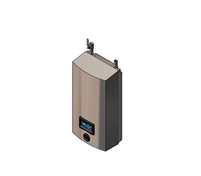
Atbilstības deklarācija                                          UA
                                                                          Свідчення про відповідність
Sabiedrība Nilfisk FOOD ar pilnu atbildību dara zināmu, ka produkti
MU, MD, HYBRID-BW, PEGASUS-BW, BF4, BF8, uz kuriem                    вимогам
attiecas šis paziņojums, atbilst šādām Padomes direktīvām par         Компанія Nilfisk FOOD заявляє про свою виключну відповідаль-
tuvināšanos EK dalībvalstu likumdošanas normām:                       ність за те, що продукти MU, MD, HYBRID-BW, PEGASUS-BW,
Mašīnbūves direktīva (2006/42/EK).                                    BF4, BF8, на які поширюється дана декларація, відповідають
-       EN 60335-2-79 : 2012                                          таким рекомендаціям Ради з уніфікації правових норм країн
Elektromagnētiskās saderības direktīva (2014/30/EU).                  -членів ЕС:
-       EN 55014-1 : 2017                                             Механічні прилади (2006/42/ЕС).
-       EN 55014-2 : 2015                                             -       EN 60335-2-79 : 2012
-       EN 61000-3-2 : 2014                                           Електромагнітна сумісність (2014/30/EU).
-       EN 61000-3-3 : 2013.                                          -       EN 55014-1 : 2017
                                                                      -       EN 55014-2 : 2015
                                                                      -       EN 61000-3-2 : 2014
                                                                      -      EN 61000-3-3 : 2013.

Technical file responsible:                                           Signature:
Flemming Asp
Nilfisk FOOD
Blytaekkervej 2
9000 Aalborg, Denmark
                                                                      Flemming Asp
                                                                      R & D Manager
                                                                      Aalborg d. 01-08-2014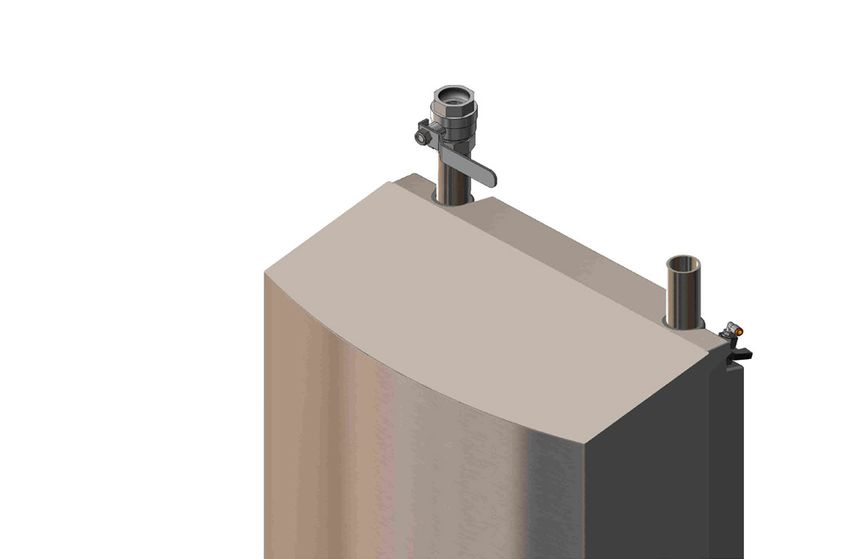
Table of Contents

English (EN)
Directions for Use................................................	�������������������������������������������������������������������������������������������� 8 - 21

Deutsch (DE)
Gebrauchsanweisung..........................................	�������������������������������������������������������������������������������������������� 22-35

Français (FR)
Mode d'emploi.....................................................	�������������������������������������������������������������������������������������������� 36-49

Español (ES)
Instrucciones de uso...........................................	�������������������������������������������������������������������������������������������� 50-63

.

English (EN)

               1.1. Contents
                    Contents.................................................................................................... 8

               2.       Symbols used in this document	������������������������������������������������������������������������ 10

               3.       General information.. . . . . . . . . . . . . . . . . . . . . . . . . . . . . . . . . . . . . . . . . . . . . . . . . . . . . . . . . . . . . . . . . . . . . . . . . . . . . . . . . . . . . . 11
                         3.1.   Identification Plate. . . . . . . . . . . . . . . . . . . . . . . . . . . . . . . . . . . . . . . . . . . . . . . . . . . . . . . . . . . . . . . . . . . . . . . . . . . . . . . . . . 12
                         3.2.   Supplier. . . . . . . . . . . . . . . . . . . . . . . . . . . . . . . . . . . . . . . . . . . . . . . . . . . . . . . . . . . . . . . . . . . . . . . . . . . . . . . . . . . . . . . . . . . . 12
                         3.3.   Specifications.. . . . . . . . . . . . . . . . . . . . . . . . . . . . . . . . . . . . . . . . . . . . . . . . . . . . . . . . . . . . . . . . . . . . . . . . . . . . . . . . . . . . . . 13

               4.       Overview and Use.. . . . . . . . . . . . . . . . . . . . . . . . . . . . . . . . . . . . . . . . . . . . . . . . . . . . . . . . . . . . . . . . . . . . . . . . . . . . . . . . . . . . . . . . 14

               5.       System Safety. . . . . . . . . . . . . . . . . . . . . . . . . . . . . . . . . . . . . . . . . . . . . . . . . . . . . . . . . . . . . . . . . . . . . . . . . . . . . . . . . . . . . . . . . . . . . 14
                         5.1.  Closing valve for water supply.	���������������������������������������������������������������������� 14
                         5.2.  Anticipated failures. . . . . . . . . . . . . . . . . . . . . . . . . . . . . . . . . . . . . . . . . . . . . . . . . . . . . . . . . . . . . . . . . . . . . . . . . . . . . . . . . . 14
                         5.3.  Rest Risk.. . . . . . . . . . . . . . . . . . . . . . . . . . . . . . . . . . . . . . . . . . . . . . . . . . . . . . . . . . . . . . . . . . . . . . . . . . . . . . . . . . . . . . . . . . 14

               6.       Installation.. . . . . . . . . . . . . . . . . . . . . . . . . . . . . . . . . . . . . . . . . . . . . . . . . . . . . . . . . . . . . . . . . . . . . . . . . . . . . . . . . . . . . . . . . . . . . . . . 15
                          6.1.    Noise. . . . . . . . . . . . . . . . . . . . . . . . . . . . . . . . . . . . . . . . . . . . . . . . . . . . . . . . . . . . . . . . . . . . . . . . . . . . . . . . . . . . . . . . . . . . . . 15
                          6.2.    Directions for Mounting	����������������������������������������������������������������������������� 15
                          6.3.    Transportation. . . . . . . . . . . . . . . . . . . . . . . . . . . . . . . . . . . . . . . . . . . . . . . . . . . . . . . . . . . . . . . . . . . . . . . . . . . . . . . . . . . . . . 15
                          6.4.    Vibrations. . . . . . . . . . . . . . . . . . . . . . . . . . . . . . . . . . . . . . . . . . . . . . . . . . . . . . . . . . . . . . . . . . . . . . . . . . . . . . . . . . . . . . . . . . 15
                          6.5.    Power Supply.. . . . . . . . . . . . . . . . . . . . . . . . . . . . . . . . . . . . . . . . . . . . . . . . . . . . . . . . . . . . . . . . . . . . . . . . . . . . . . . . . . . . . . 15
                          6.6.    Earth Leakage Circuit Breaker (ELCB).	������������������������������������������������������������ 15
                          6.7.    Water Connection. . . . . . . . . . . . . . . . . . . . . . . . . . . . . . . . . . . . . . . . . . . . . . . . . . . . . . . . . . . . . . . . . . . . . . . . . . . . . . . . . . . 16
                          6.8.    Air Connection. . . . . . . . . . . . . . . . . . . . . . . . . . . . . . . . . . . . . . . . . . . . . . . . . . . . . . . . . . . . . . . . . . . . . . . . . . . . . . . . . . . . . . 16

               7.       Operation procedures. . . . . . . . . . . . . . . . . . . . . . . . . . . . . . . . . . . . . . . . . . . . . . . . . . . . . . . . . . . . . . . . . . . . . . . . . . . . . . . . . . . . 16
                         7.1.    Start up. . . . . . . . . . . . . . . . . . . . . . . . . . . . . . . . . . . . . . . . . . . . . . . . . . . . . . . . . . . . . . . . . . . . . . . . . . . . . . . . . . . . . . . . . . . . 16
                            7.1.1.     New System	��������������������������������������������������������������������������������� 16
                         7.2.    New system. . . . . . . . . . . . . . . . . . . . . . . . . . . . . . . . . . . . . . . . . . . . . . . . . . . . . . . . . . . . . . . . . . . . . . . . . . . . . . . . . . . . . . . . 16
                            7.2.1.     Long Stops	���������������������������������������������������������������������������������� 16
                            7.2.2.     Start	                                                                                                                                                                                    17
                            7.2.3.     Stop	                                                                                                                                                                                     17

               8.	Operation. . . . . . . . . . . . . . . . . . . . . . . . . . . . . . . . . . . . . . . . . . . . . . . . . . . . . . . . . . . . . . . . . . . . . . . . . . . . . . . . . . . . . . . . . . . . . . . . . . 17
                    8.1.   Before Operation . . . . . . . . . . . . . . . . . . . . . . . . . . . . . . . . . . . . . . . . . . . . . . . . . . . . . . . . . . . . . . . . . . . . . . . . . . . . . . . . . . 17
                    8.2.   Start/Stop (change, rinse, foam, des)	���������������������������������������������������������������� 17

               9.       Maintenance, Trouble shooting, Service	��������������������������������������������������������������� 18
                         9.1.    Installation Instruction for Flow Switch	��������������������������������������������������������������� 18
                         9.2.     Components. . . . . . . . . . . . . . . . . . . . . . . . . . . . . . . . . . . . . . . . . . . . . . . . . . . . . . . . . . . . . . . . . . . . . . . . . . . . . . . . . . . . . . . 18
                            9.2.1.      Pumps/motor 	�������������������������������������������������������������������������������� 18
                            9.2.2.      Control system	������������������������������������������������������������������������������� 18
                            9.2.3.      Flow switch	���������������������������������������������������������������������������������� 18
                         9.3.    Preventive maintenance	���������������������������������������������������������������������������� 18
                         9.4.    Internal cleaning of the unit	������������������������������������������������������������������������� 18
                         9.5.    Trouble Shooting and Remedy	���������������������������������������������������������������������� 19
                         9.6.    Service address. . . . . . . . . . . . . . . . . . . . . . . . . . . . . . . . . . . . . . . . . . . . . . . . . . . . . . . . . . . . . . . . . . . . . . . . . . . . . . . . . . . . 19

               10. Tools. . . . . . . . . . . . . . . . . . . . . . . . . . . . . . . . . . . . . . . . . . . . . . . . . . . . . . . . . . . . . . . . . . . . . . . . . . . . . . . . . . . . . . . . . . . . . . . . . . . . . . . 20

               11. End of Use.. . . . . . . . . . . . . . . . . . . . . . . . . . . . . . . . . . . . . . . . . . . . . . . . . . . . . . . . . . . . . . . . . . . . . . . . . . . . . . . . . . . . . . . . . . . . . . . . 21
                    11.1. Dismounting . . . . . . . . . . . . . . . . . . . . . . . . . . . . . . . . . . . . . . . . . . . . . . . . . . . . . . . . . . . . . . . . . . . . . . . . . . . . . . . . . . . . . . . 21
                    11.2. Disposal.. . . . . . . . . . . . . . . . . . . . . . . . . . . . . . . . . . . . . . . . . . . . . . . . . . . . . . . . . . . . . . . . . . . . . . . . . . . . . . . . . . . . . . . . . . . 21

               8
English (EN)
Recommended Spare parts ���������������������������������������������������������������������������� 65
Pegasus BW4. . . . . . . . . . . . . . . . . . . . . . . . . . . . . . . . . . . . . . . . . . . . . . . . . . . . . . . . . . . . . . . . . . . . . . . . . . . . . . . . . . . . . . . . . . . . 66
Hybrid BW4/BW7. . . . . . . . . . . . . . . . . . . . . . . . . . . . . . . . . . . . . . . . . . . . . . . . . . . . . . . . . . . . . . . . . . . . . . . . . . . . . . . . . . . . . . . . . 68
Hybrid BF4/Hybrid BF8. . . . . . . . . . . . . . . . . . . . . . . . . . . . . . . . . . . . . . . . . . . . . . . . . . . . . . . . . . . . . . . . . . . . . . . . . . . . . . . . . . 70
Inlet pipe.. . . . . . . . . . . . . . . . . . . . . . . . . . . . . . . . . . . . . . . . . . . . . . . . . . . . . . . . . . . . . . . . . . . . . . . . . . . . . . . . . . . . . . . . . . . . . . . . . 72
Outlet pipe.. . . . . . . . . . . . . . . . . . . . . . . . . . . . . . . . . . . . . . . . . . . . . . . . . . . . . . . . . . . . . . . . . . . . . . . . . . . . . . . . . . . . . . . . . . . . . . . 74
Controller Pegasus BW4, Hybrid BW4, Hybrid BF4 ��������������������������������������������������� 76
Controller BW7/BF8.. . . . . . . . . . . . . . . . . . . . . . . . . . . . . . . . . . . . . . . . . . . . . . . . . . . . . . . . . . . . . . . . . . . . . . . . . . . . . . . . . . . . . 78
Hybrid Display BF4/BF8. . . . . . . . . . . . . . . . . . . . . . . . . . . . . . . . . . . . . . . . . . . . . . . . . . . . . . . . . . . . . . . . . . . . . . . . . . . . . . . . . 80
Pipe holder system. . . . . . . . . . . . . . . . . . . . . . . . . . . . . . . . . . . . . . . . . . . . . . . . . . . . . . . . . . . . . . . . . . . . . . . . . . . . . . . . . . . . . . 82
Operating diagrams.. . . . . . . . . . . . . . . . . . . . . . . . . . . . . . . . . . . . . . . . . . . . . . . . . . . . . . . . . . . . . . . . . . . . . . . . . . . . . . . . . . . . . 84
Electrical diagrams. . . . . . . . . . . . . . . . . . . . . . . . . . . . . . . . . . . . . . . . . . . . . . . . . . . . . . . . . . . . . . . . . . . . . . . . . . . . . . . . . . . . . . 85
Sensor diagram. . . . . . . . . . . . . . . . . . . . . . . . . . . . . . . . . . . . . . . . . . . . . . . . . . . . . . . . . . . . . . . . . . . . . . . . . . . . . . . . . . . . . . . . . . 86
Pump curves. . . . . . . . . . . . . . . . . . . . . . . . . . . . . . . . . . . . . . . . . . . . . . . . . . . . . . . . . . . . . . . . . . . . . . . . . . . . . . . . . . . . . . . . . . . . . 87
Installation.. . . . . . . . . . . . . . . . . . . . . . . . . . . . . . . . . . . . . . . . . . . . . . . . . . . . . . . . . . . . . . . . . . . . . . . . . . . . . . . . . . . . . . . . . . . . . . . 90
Mounting Pegaus/Hybrid ������������������������������������������������������������������������������� 93
Layout Hybrid BW4, BW7/Pegasus BW4 ������������������������������������������������������������������
9English (EN)
2. Symbols used in this document
Read before Use
Wear glasses when using the unit.
Wear gloves and suitable clothing when using the unit.
Note:
A potentially damaging situation.
Possible consequences: The product or something in its
vicinity could be damaged prevention.
Caution:
A dangerous situation.'Possible consequences: light or minor
injuries. Can also be used in warn against damage to prop-
erty or other goods prevention.
Warning:
A Potentially dangerous situation.
Possible consequences: Death or severe injury prevention.
Danger:
A dangerous situation.
Possible consequences: Death or severe injury prevention.
Danger:
Risc of electric shock!
Possible consequences: Death or severe injury prevention
Hot Surfaces
Risc of burns!
Possible consequences: Severe injuries prevention
10English (EN)
3. General information
Nilfisk FOOD congratulates you on
your new low-pressure foam and
sanitising cleaning equipment.
The equipment provides the lat-
est standard of technology in low
pressure cleaning equipment in
your factory.
The equipment can be used for
the supply of pressurised water to
a/multiple cleaning unit(s).
It is important that your operational
staff read these directions for use
prior to installation, start up and
use of the equipment.
11English (EN)
3.1. Identification Plate
1 3 2
Nilfisk FOOD, Blytækkervej 2, DK - 9000 Aalborg
5 Hybrid - BW4
Art. no. 110003425
4 Date 20.08.2012 S/N 88910
Pressure Max 2,50 MPa Weight 120 kg
6 Water Max 120 L/min
Max Temp 70,00 °C
9
400 V 50 Hz 10,6 Amp
10
7 8 11 12
1. Producer
2. Serial no
3. Type
4. Date of production
5. Article no
6. Maximum pressure
7. Supply voltage
8. Frequency
9. Maximum water consumption
10. Maximum temperature
11. Current
12. Weight
3.2. Supplier
Nilfisk FOOD
Blytækkervej 2
DK-9000 Aalborg, Denmark
Tel.: +45 7218 2000
CVR no. 6257 2213
www.nilfiskfood.com
12English (EN)
3.3. Specifications
Technical data
Water BF4, BWP4 & BW4 BW7 & BF8
Connection type inlet ISO 228/1-G 1 1/4" ISO 228/1-G 1 1/4"
Connection type outlet ISO 228/1-G 1 1/4" ISO 228/1-G 1 1/4"
Recommended inlet pipe 1 1/4" 2"
dimension (min)
Recommended outlet pipe BF4: 1 1/4" 2"
dimension (min) BWP4: 1 1/4"
BW4: 1 1/4"
Pump pressure 20 bar 20 bar
Adjustable operational pressure 20 bar + inlet (max 25 bar) BW7:20 bar + inlet (max 22 bar)
BW8: 20 bar + inlet (max 25 bar)
Operational flow range 10-120 l/min BW7: 2 bar @ 210 l/min
BF8: 2 bar @ 240 l/min
Min. inlet pressure 2 bar @ 120 l/min BW7: 10-210 l/min
BF8: 10-240 l/min
Max. inlet pressure 8 bar 8 bar
Max. water temperature 70°C 70°C
Electricity
Power consumption 5,5 kW BW7: 10kW
BF8: 11kW
Nom. current 14,2 A 27 A
Supply 3/PE 400 3/PE 400
Vac ±10% Vac ±10%
50/60Hz 50/60Hz
Security of electrical wiring 16A 35A
Electrical cable; L1 L2, L3, PE 4 x 2.5 mm 2
4x6.0 mm2
General
IP class IP55 IP55
Sound level ISO 11202 Below 70dB Below 70dB
Weight BF4: 60 kg BW7: 120 kg
BWP4: 85 kg BF8: 75 kg
BW4: 100 kg
Dimensions H x W x D BF4: 1310x560x400 mm BW7: 1074x560x385 mm
BWP4: 785x550x375 mm Bf8: 1000x550x400 mm
BW4: 1074x560x385 mm
13English (EN)
5.2. Anticipated failures
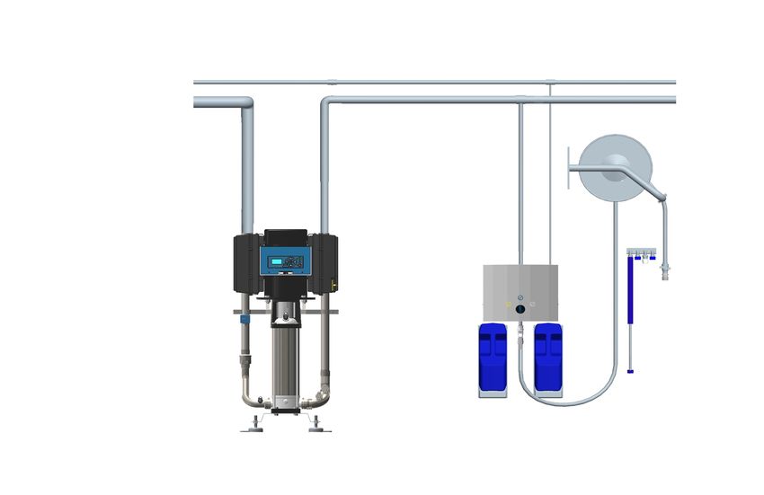
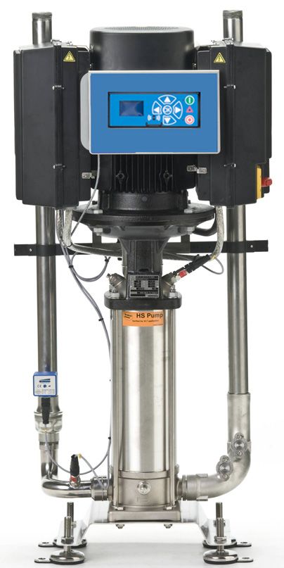
4. Overview and Use Breakdown of non-return valves for water:
The Booster in the Fable range is a completely func- • The unit must never be used without the cover
tioning pumping station that supllies pressurised wa- beeing mounted.
ter to connected satellite hygiene stations. Therefore • Water closing valve on/in connection with the unit
the Booster must be supplied with: water in sufficient must always be closed when the unit is not in use.
quantity and power. • Non-return valves for air and water should be
The station is then ready for hygiene duties. examined minimum once a year by authorised
personel for defects.
Repair of unit:
Warning: Do not use the water from
• Do not attempt to repair a defect unit by yourself.
the system for applications other than
Always contact an authorised service company.
cleaning.
• Block and mark any defect unit in order to avoid
Before installation and set up of the unit always unintended use - se paragraf below regarding
read this instruction thoroughly. Always make sure "Rest risk - Use of the unit”
to follow personal safty procedures for chemicals in • For safety reasons only use approved and original
connection with refilling procedures (product change), spare parts.
maintenance and repair. See also product label and
MSDS sheet. 5.3. Rest Risk
Use of Unit:
Safety instructions • Never use the unit without prior instructions in use
Only professional service personel are allowed to of the unit and its safety instructions. The instruc-
carry out service and repairs on the unit. tion must be prepared by an educated/instructed
personel.
Only instructed personel are allowed to operate the • Never use the unit without having read the en-
unit. closed guide and safety instructions.
• Always close water after use.
5. System Safety Damaged unit:
• Never use the unit if leakages (water) is observed.
In case of error/defect or service on equipment: • Never use the unit if it is not possible to operate
1. close the water supply the closing valves and/or if it is not possible to
select required operation.
5.1. Closing valve for water supply.
• Never use the unit if it has been dislodged for its
With this valve the unit can be isolated from the water
original place of mounting.
supply.
Open
Closed
110003601
Wear glasses when using the unit.
Wear gloves and suitable clothing
when using the unit.
14English (EN)
6. Installation
Mains
For safety reasons it is important to read all of the 3/PE 400 Vac ± 10%
enclosed information before installation of this equip- 48 Hz ... 62 Hz
ment. In addition, the legislation in force at the time of
L1
purchase must always be considered in connection
with the installation and mounting of this equipment,
L2
no matter the contents of this manual.If there are mat-
ters of dispute please contact your dealer.
L3
6.1. Noise
Sound level according to ISO 11202; Below 70 dB.
PE
6.2. Directions for Mounting
• The unit should be mounted in frost- Green/Yellow L3 L2 L1
free rooms only.
Note: Phase sequence unimportant.
• The unit can be mounted on a wall Connecting cable.
or on a separate frame which may
be installed in production areas and
anchored to the floor.
• For mounting on walls, please note BW3 BW4 BW7
the following: Voltage 3/PE 400 Vac 3/PE 400 Vac 3/PE 400 Vac
• The wall for mounting should be ±10% ±10% ±10%
either a stable brick wall or a wall
made of concrete. Frequency 50/60 Hz 50/60 Hz 50/60 Hz
48 -0%…62 48 -0%…62 +0% 48 -0%…62
+0% +0%
Motor power 4 kW 5.5 kW 10 kW
• The delivered bracket should be
Rated current 10.6 A 14.2 A 27 A
secured to the wall by the enclosed
Fuse 16 A 20 A 35 A
screws and corresponding dowels
• The wall bracket should be mounted C1, C2, C3, PE 2.5 mm² 2.5 mm² 6 mm²
on the wall according to the above
description and the station is hung on 6.6. Earth Leakage Circuit Breaker (ELCB).
to the bracket.
When using an earth leakage circuit breaker (ELCB) also
known as a residual current device (RCD) or a residual
6.3. Transportation
current circuit breaker (RCCB) in a system that incorpo-
For secure transportation of the unit, we recommend
rates a variable speed drive connected to 3 phase 400 V.
always to ensure, that the unit can not slide or tip. The trip level of the ELCB has to be 300 mA.
The unit might have to be secured with straps. (30 mA used in house hold will malfunction due to earth
Transportation of the unit only in horisontal position: leakage)
The unit must not be placed on the front where you
find the operation panel. Neither can it be placed Service Switch:
on top or bottom where connections and outlets are The unit must always be connected to the main sup-
mounted. ply through a separate service switch.
In case the unit is moved at a temperature of approx NB! Installation must always be in accordence with
or below 0°C (32°F), you must always make sure that local legistration.
the the unit has been fully emptied for water. If this is
not the case, you may damage the unit.
6.4. Vibrations
Hand-arm vibrations according to ISO 5349-1.
6.5. Power Supply
Connection instruction is mounted on the cables.
The phase order is subordinated.
15English (EN)
6.7. Water Connection
7. Operation procedures
• Before the unit is connected to the
water supply pipe, the supply line 7.1. Start up
should be rinsed carefully in order 7.1.1. New System
to remove coarse impurities and Note: The pump should be bled and filled with water
metal shavings. before start.
• The connection for water must be
7.2. New system
made at the top of the unit. (see
layout drawing). In order to ensure a problem-free start up of a new
• Minimum internal diameter of the system the pipe system must be flushed and bled.
supply pipe must be at least 1 1/4” Bleeding the pipe system
external (ø36mm internal). 1. Turn on the water supply to rinse and bleed the
• The unit must be fitted with a clos- entire system. If satellites are installed open the
ing valve for water on the inlet (see tap furthest away until no air or dirt comes out.
Then rinse and bleed the next tap and continue
drawing 110003601).
until the tap closest to you has been rinsed and
bled.
• The pressure loss in the supply line 2. Mount satellites, if any
must be held as low as possible by
- avoiding long supply pipes Bleeding the pump
- mounting low pressure resistance 3. Loosen the relief plug (A) 1-2 revolutions until
water and air begin to flow out.
ball valves and
- avoiding fittings with high pressure
loss. A
• When installing the piping, take care
to avoid air traps.
• All pipe connections to the unit must
be screwed connections ensuring
simple maintenance and dismantling
DETAIL A 0627131A
of the station.
Max. allowed temperature of supply water: 70°C
Max. allowed pressure of supply water: 2-8 bar
For an optimum functioning we recom- Never loosen the relief plug while the pump
mend installing a filter on the inlet to is running as this may damage the packing.
avoid impurities. Min. Filter mesh size
800µ -> 1500μ.
6.8. Air Connection 4. Tighten the relief plug again
5. Start the pump so that all remaining air pockets
are forced up to the top of the pump.
6. Stop the pump
A 7. Loosen the relief plug 1-2 revolutions again and
bleed the system until only water flows out.
8. Tighten the relief plug once more
The booster is now ready for operation.
Water inlet
Press “I” on the control panel.
110003290
7.2.1. Long Stops
If long productions stops are planned (more than 6
months) and the pump is emptied of water, it is rec-
ommended that the pump be secured as follows:
1. Remove the coupling safety guard.
2. Spray a couple of drops of silicone oil onto
the axle between the top section and the
coupling.
16English (EN)
Carefully follow the instructions given in the manual 8. Operation
Never store or install the equipment where the ambi-
ent temperature is above 40°C or gets at or below the 8.1. Before Operation
freezing point.
If the wall the unit is to be mounted on is made of
7.2.2. Start bricks or concrete, the enclosed screws and rawl
1. Make sure that the water supply to the unit is plugs are usable, otherwise you have to make sure
open. that the carrying capacity of the wall is sufficient.
2. Select requested function. Use the unit according
The pipeline must be rinsed through
to the ”Software manual”.
before the system is connected.
7.2.3. Stop
1. Close the water supply (see drawing 110003601).
Remove cover before the unit is
Due to the following it is very important
mounted on the wall.
to close the water supply when the unit is
not in use.
8.2. Start/Stop (change, rinse, foam, des)
2. Depending on usage, maintenance should be
undertaken by an authorised service engineer at Start booster
least once a year in order to prevent defects and 1. Check that water suppy for the system is open.
failure of operation. Authorised engineers are
persons who due to their skills and experience Stop booster
have sufficient knowledge of Hygiene Systems 2. Turn off the water supply.
and are confident with the state work safety regu-
lations, accident preventing regulations, lines and It is important to shut off the water
generally acknowledged technical regulations when the unit is left after use .
such as DIN-norms and VDE-provisions. For
your safety, this cleaning unit has been manufac-
tured according to all relevant regulations valid It may be necessary to bleed the pipes and the unit
in the EU and therefore it has been supplied with again after it has been closed for a longer period of
the CE-marking. For further information, please time (holidays, and the like)
refer to the service department.
3. It is recommended to clean the surface inside the
unit at least once a month in order to maintain
parts and avoid corrosion of parts.
17English (EN)
9.2. Components
9. Maintenance, Trouble shooting,
9.2.1. Pumps/motor
Service Pumps/motor are maintenance free.
Service may only be carried out by authorized and 9.2.2. Control system
qualified personnel.
CAUTION Maintenance free
The system must only be serviced when If defective: Call a service technician
there is no voltage or pressure on the sys-
tem 9.2.3. Flow switch
1. Turn off the main switch at the control box Maintenance-free.
2. Open a water outlet to depressurise the syste
9.1. Installation Instruction for Flow Switch If defective, replace the flow switch.
1. Press "0" on the control pane to stop the system.
There is a dot on one of the nut surfaces on the 2. Remove the cover
sensor. This is used to position the contact point of 3. Turn "rinse/foam" handle on a satellite to foam
the sensor in relation to the direction of flow of the position.
medium. 4. Activate the spray handle on the outlet hose of
the satellite so water runs out.
5. Check that the flow switch is turned the correct
way (the wire must follow direction).
6. Turn the brass screw at the bottom of the hole
until a green diode lights up.
7. Close the spray handle again and check that the
red diode lights up.
8. Mount the cover.
110000973
9.3. Preventive maintenance
This marking must be located within an angle of +/-
Depending on usage, maintenance should be un-
30° perpendicular to the direction of flow, as shown in
dertaken by an authorised service engineer at least
the example.
once a year in order to prevent defects and failure of
operation. Authorised engineers are persons who due
to their skills and experience have sufficient knowl-
edge of the Booster Systems and are confident with
the state work safety regulations, accident prevent-
Mark
ing regulations, lines and generally acknowledged
technical regulations such as DIN-norms and VDE-
Flow
provisions. For your safety, this unit has been manu-
30°
30°
110002490 factured according to all relevant regulations valid in
Diagram of sensor fitted in a pipe. the EU and therefore it has been supplied with the
CE-marking. For further information, please refer to
the service department.
9.4. Internal cleaning of the unit
We recommend opening and cleaning the unit inside
30° min. once a month.
30°
110002491
Loctite 577 is used at the factory to seal the thread,
but packing yarn/packing tape can also be used.
18English (EN)
9.5. Trouble Shooting and Remedy
In case of errors/troubles not mentioned above, please contact your local service technician for further assis-
tance.
9.6. Service address
Please see the back cover of this manual
Symptoms Possible Causes Remedy
The unit does not start • Is there voltage to the unit • Reconnect voltage
• Fuse blown • Call technician
• Display lights up, but the unit • Go to setup -> Settings menu
does not start after reconnect- -> Startup method,
ing voltage and set it to pressure
• Unit starts after changing • Set unit back to flow start in
startup method setup menu
• After reactivating flow start • Try to re-adjust flow switch
The "Δ" lamp on the controlpanel is • Error messages on display • Press "0" wait for a few sec-
flashing onds and then press "1"on
the control panel to restart the
system.
• Error after restart • Go to software manual
No pressure/too low pressure • Insufficient or No water supply • Open water supply valve
• Is the filter if any clogged • Clean the filter
• Is the pump leaking or making • Call technician
jarring sounds
• Rinsing nozzle not installed • Place rinsing nozzle
19English (EN)
10. Tools
Standard tools that are useful/necessary for service and maintenance on the full range of equipment
BF/BW & MB Booster Satellites
Mainstation BF/BW & MB Booster
Foamatic Mainstation Mainstation
Foamatic Satellites
Foamatic Mainstation
Satellites Satellites
BF/BW & MB Booster BF/BW & MB Booster
Mainstation Mainstation
Foamatic Satellites T15, T20, T25 Foamatic Satellites
Foamatic Mainstation Foamatic Mainstation
0,5x3mm
1x5,5 mm
10, 11, 12, 13,
14, 15, 17, 19 mm
PH1, PH2
BF/BW & MB Booster Foamatic Satellites
Foamatic Mainstation
Satellites Satellites
BF/BW & MB Booster Mainstation
Mainstation Foamatic Satellites
Foamatic Satellites Foamatic Mainstation
Foamatic Mainstation
20English (EN)
11. End of Use
11.1. Dismounting
Close supply valve and remove the unit from wall.
11.2. Disposal
In case the unit should be disposed, it must be separated and sorted in eg-recyclable and non recyclable parts.
The steel construction is easily separated and disposed and constitutes no environmental risk - nor for the
user.
Disposal must be made according to rules and regulations in force for disposal of machines as well as all
standards in connection with environmental protection.
CAUTION
Disposal of electronic components
and other remedies must be handled
as special disposal when disposed.
Alternatively, it can be disposed by a
specialised disposal company.
.
211. Inhalt
1. Inhalt.. . . . . . . . . . . . . . . . . . . . . . . . . . . . . . . . . . . . . . . . . . . . . . . . . . . . . . . . . . . . . . . . . . . . . . . . . . . . . . . . . . . . . . . . . . . . . . . . . . . . . 22
2. In diesem Dokument verwendete Symbole ������������������������������������������������������������� 24
3. Allgemeine Informationen ������������������������������������������������������������������������������� 25
3.1. Kennzeichnungsschild ������������������������������������������������������������������������������ 26
3.2. Anbieter. . . . . . . . . . . . . . . . . . . . . . . . . . . . . . . . . . . . . . . . . . . . . . . . . . . . . . . . . . . . . . . . . . . . . . . . . . . . . . . . . . . . . . . . . . . . 26
3.3. Spezifikationen. . . . . . . . . . . . . . . . . . . . . . . . . . . . . . . . . . . . . . . . . . . . . . . . . . . . . . . . . . . . . . . . . . . . . . . . . . . . . . . . . . . . . 27
4. Überblick und Gebrauch.. . . . . . . . . . . . . . . . . . . . . . . . . . . . . . . . . . . . . . . . . . . . . . . . . . . . . . . . . . . . . . . . . . . . . . . . . . . . . . . . . 28
5. Systemsicherheit. . . . . . . . . . . . . . . . . . . . . . . . . . . . . . . . . . . . . . . . . . . . . . . . . . . . . . . . . . . . . . . . . . . . . . . . . . . . . . . . . . . . . . . . . 28
5.1. Verschlussventil für Wasserzufuhr. (Zubehör) �������������������������������������������������������� 28
Deutsch (DE)
5.2. Voraussichtliche Ausfälle ��������������������������������������������������������������������������� 28
5.3. Restrisiko. . . . . . . . . . . . . . . . . . . . . . . . . . . . . . . . . . . . . . . . . . . . . . . . . . . . . . . . . . . . . . . . . . . . . . . . . . . . . . . . . . . . . . . . . . 28
6. Installation.. . . . . . . . . . . . . . . . . . . . . . . . . . . . . . . . . . . . . . . . . . . . . . . . . . . . . . . . . . . . . . . . . . . . . . . . . . . . . . . . . . . . . . . . . . . . . . . . 28
6.1. Störgeräusche. . . . . . . . . . . . . . . . . . . . . . . . . . . . . . . . . . . . . . . . . . . . . . . . . . . . . . . . . . . . . . . . . . . . . . . . . . . . . . . . . . . . . . 28
6.2. Montageanleitung. . . . . . . . . . . . . . . . . . . . . . . . . . . . . . . . . . . . . . . . . . . . . . . . . . . . . . . . . . . . . . . . . . . . . . . . . . . . . . . . . . . 29
6.3. Transport.. . . . . . . . . . . . . . . . . . . . . . . . . . . . . . . . . . . . . . . . . . . . . . . . . . . . . . . . . . . . . . . . . . . . . . . . . . . . . . . . . . . . . . . . . . 29
6.4. Vibrationen. . . . . . . . . . . . . . . . . . . . . . . . . . . . . . . . . . . . . . . . . . . . . . . . . . . . . . . . . . . . . . . . . . . . . . . . . . . . . . . . . . . . . . . . . 29
6.5. Stromversorgung. . . . . . . . . . . . . . . . . . . . . . . . . . . . . . . . . . . . . . . . . . . . . . . . . . . . . . . . . . . . . . . . . . . . . . . . . . . . . . . . . . . 29
6.6. Fehlerstromschutzschalter (ELCB). ������������������������������������������������������������������ 29
6.7. Wasseranschluss. . . . . . . . . . . . . . . . . . . . . . . . . . . . . . . . . . . . . . . . . . . . . . . . . . . . . . . . . . . . . . . . . . . . . . . . . . . . . . . . . . . 29
6.8. Luftanschluss.. . . . . . . . . . . . . . . . . . . . . . . . . . . . . . . . . . . . . . . . . . . . . . . . . . . . . . . . . . . . . . . . . . . . . . . . . . . . . . . . . . . . . . 30
7. Betriebsverfahren. . . . . . . . . . . . . . . . . . . . . . . . . . . . . . . . . . . . . . . . . . . . . . . . . . . . . . . . . . . . . . . . . . . . . . . . . . . . . . . . . . . . . . . . . 30
7.1. Inbetriebnahme. . . . . . . . . . . . . . . . . . . . . . . . . . . . . . . . . . . . . . . . . . . . . . . . . . . . . . . . . . . . . . . . . . . . . . . . . . . . . . . . . . . . . 30
7.1.1. Neues System ������������������������������������������������������������������������������� 30
7.2. Neues System. . . . . . . . . . . . . . . . . . . . . . . . . . . . . . . . . . . . . . . . . . . . . . . . . . . . . . . . . . . . . . . . . . . . . . . . . . . . . . . . . . . . . . 30
7.2.1. Langer Produktionsstillstand ������������������������������������������������������������������ 30
7.2.2. Start 31
7.2.3. Stopp 31
7.3. Wartung, Problemanalyse und Kundendienst �������������������������������������������������������� 31
8. Betrieb. . . . . . . . . . . . . . . . . . . . . . . . . . . . . . . . . . . . . . . . . . . . . . . . . . . . . . . . . . . . . . . . . . . . . . . . . . . . . . . . . . . . . . . . . . . . . . . . . . . . . 31
8.1. Vor dem Betrieb . . . . . . . . . . . . . . . . . . . . . . . . . . . . . . . . . . . . . . . . . . . . . . . . . . . . . . . . . . . . . . . . . . . . . . . . . . . . . . . . . . . 31
9. Wartung, Problemanalyse und Kundendienst ���������������������������������������������������������� 32
9.1. Installationsanleitung für den Durchflussschalter ����������������������������������������������������� 32
9.2. Komponenten. . . . . . . . . . . . . . . . . . . . . . . . . . . . . . . . . . . . . . . . . . . . . . . . . . . . . . . . . . . . . . . . . . . . . . . . . . . . . . . . . . . . . . 32
9.2.1. Pumpen/Motor ������������������������������������������������������������������������������ 32
9.2.2. Kontrollsystem ������������������������������������������������������������������������������� 32
9.2.3. Durchflussschalter ��������������������������������������������������������������������������� 32
9.3. Vorbeugende Wartung ����������������������������������������������������������������������������� 32
9.4. Innenreinigung des Geräts �������������������������������������������������������������������������� 32
9.5. Fehlersuche und Behandlung ����������������������������������������������������������������������� 33
9.6. Serviceadresse. . . . . . . . . . . . . . . . . . . . . . . . . . . . . . . . . . . . . . . . . . . . . . . . . . . . . . . . . . . . . . . . . . . . . . . . . . . . . . . . . . . . . 33
10. Werkzeuge. . . . . . . . . . . . . . . . . . . . . . . . . . . . . . . . . . . . . . . . . . . . . . . . . . . . . . . . . . . . . . . . . . . . . . . . . . . . . . . . . . . . . . . . . . . . . . . . . 34
11. Nach Verwendung.. . . . . . . . . . . . . . . . . . . . . . . . . . . . . . . . . . . . . . . . . . . . . . . . . . . . . . . . . . . . . . . . . . . . . . . . . . . . . . . . . . . . . . . . 35
11.1. Demontage. . . . . . . . . . . . . . . . . . . . . . . . . . . . . . . . . . . . . . . . . . . . . . . . . . . . . . . . . . . . . . . . . . . . . . . . . . . . . . . . . . . . . . . . . 35
11.2. Entsorgung. . . . . . . . . . . . . . . . . . . . . . . . . . . . . . . . . . . . . . . . . . . . . . . . . . . . . . . . . . . . . . . . . . . . . . . . . . . . . . . . . . . . . . . . . 35
22Recommended Spare parts ���������������������������������������������������������������������������� 65
Pegasus BW4. . . . . . . . . . . . . . . . . . . . . . . . . . . . . . . . . . . . . . . . . . . . . . . . . . . . . . . . . . . . . . . . . . . . . . . . . . . . . . . . . . . . . . . . . . . . 66
Hybrid BW4/BW7. . . . . . . . . . . . . . . . . . . . . . . . . . . . . . . . . . . . . . . . . . . . . . . . . . . . . . . . . . . . . . . . . . . . . . . . . . . . . . . . . . . . . . . . . 68
Hybrid BF4/Hybrid BF8. . . . . . . . . . . . . . . . . . . . . . . . . . . . . . . . . . . . . . . . . . . . . . . . . . . . . . . . . . . . . . . . . . . . . . . . . . . . . . . . . . 70
Inlet pipe.. . . . . . . . . . . . . . . . . . . . . . . . . . . . . . . . . . . . . . . . . . . . . . . . . . . . . . . . . . . . . . . . . . . . . . . . . . . . . . . . . . . . . . . . . . . . . . . . . 72
Outlet pipe.. . . . . . . . . . . . . . . . . . . . . . . . . . . . . . . . . . . . . . . . . . . . . . . . . . . . . . . . . . . . . . . . . . . . . . . . . . . . . . . . . . . . . . . . . . . . . . . 74
Deutsch (DE)
Controller Pegasus BW4, Hybrid BW4, Hybrid BF4 ��������������������������������������������������� 76
Controller BW7/BF8.. . . . . . . . . . . . . . . . . . . . . . . . . . . . . . . . . . . . . . . . . . . . . . . . . . . . . . . . . . . . . . . . . . . . . . . . . . . . . . . . . . . . . 78
Hybrid Display BF4/BF8. . . . . . . . . . . . . . . . . . . . . . . . . . . . . . . . . . . . . . . . . . . . . . . . . . . . . . . . . . . . . . . . . . . . . . . . . . . . . . . . . 80
Pipe holder system. . . . . . . . . . . . . . . . . . . . . . . . . . . . . . . . . . . . . . . . . . . . . . . . . . . . . . . . . . . . . . . . . . . . . . . . . . . . . . . . . . . . . . 82
Operating diagrams.. . . . . . . . . . . . . . . . . . . . . . . . . . . . . . . . . . . . . . . . . . . . . . . . . . . . . . . . . . . . . . . . . . . . . . . . . . . . . . . . . . . . . 84
Electrical diagrams. . . . . . . . . . . . . . . . . . . . . . . . . . . . . . . . . . . . . . . . . . . . . . . . . . . . . . . . . . . . . . . . . . . . . . . . . . . . . . . . . . . . . . 85
Sensor diagram. . . . . . . . . . . . . . . . . . . . . . . . . . . . . . . . . . . . . . . . . . . . . . . . . . . . . . . . . . . . . . . . . . . . . . . . . . . . . . . . . . . . . . . . . . 86
Pump curves. . . . . . . . . . . . . . . . . . . . . . . . . . . . . . . . . . . . . . . . . . . . . . . . . . . . . . . . . . . . . . . . . . . . . . . . . . . . . . . . . . . . . . . . . . . . . 87
Installation.. . . . . . . . . . . . . . . . . . . . . . . . . . . . . . . . . . . . . . . . . . . . . . . . . . . . . . . . . . . . . . . . . . . . . . . . . . . . . . . . . . . . . . . . . . . . . . . 90
Mounting Pegaus/Hybrid ������������������������������������������������������������������������������� 93
Layout Hybrid BW4, BW7/Pegasus BW4 ������������������������������������������������������������������
232. In diesem Dokument verwendete Symbole
Bitte vor Inbetriebnahme lesen.
Bitte tragen Sie bei der Bedienung des Geräts eine Brille.
Deutsch (DE)
Bitte tragen Sie bei Benutzung des Geräts Handschuhe und
passende Kleidung.
Beachten Sie:
Eine potenziell gefährliche Situation.
Mögliche Konsequenzen: Das Produkt oder etwas in seiner
Nähe könnte beschädigt sein. Prävention.
Vorsicht:
Eine gefährliche Situation. 'Mögliche Konsequenzen: Leichte
oder geringfügige Verletzungen. Kann auch genutzt werden, um
vor Sachbeschädigung oder vor Beschädigung anderer Güter
zu warnen. Prävention.
Warnung:
Eine potenziell gefährliche Situation.
Mögliche Konsequenzen: Tod oder schwere Verletzungen.
Prävention.
Gefahr:
Eine gefährliche Situation.
Mögliche Konsequenzen: Tod oder schwere Verletzungen.
Prävention.
Gefahr:
Risiko eines elektrischen Schlags!
Mögliche Konsequenzen: Tod oder schwere Verletzungen.
Prävention
Heiße Oberfläche
Gefahr durch heiße Oberflächen.
Mögliche Konsequenzen: Schwere Verletzungen.
Prävention.
243. Allgemeine
Informationen
Nilfisk FOOD beglückwünscht Sie
zu Ihrer Niederdruckschaum- und
Desinfektionsreinigungsanlage.
Die Anlage ist auf dem neuesten
Stand der Technik im Bereich der
Niederdruck-Reinigungsanlagen in
Ihrem Betrieb.
Deutsch (DE)
Die Anlage kann zur Druckwasser
Versorgung an einer/mehrerer Reini-
gungsanlagen eingesetzt werden.
Es ist äußerst wichtig, dass Ihr op-
eratives Personal diese Anweisun-
gen vor der Installation, Inbetrieb-
nahme und der Nutzung der Geräte
durchliest.
253.1. Kennzeichnungsschild
1 3 2
Nilfisk FOOD, Blytækkervej 2, DK - 9000 Aalborg
5 Hybrid - BW4
Deutsch (DE)
Art. no. 110003425
4 Date 20.08.2012 S/N 88910
Pressure Max 2,50 MPa Weight 120 kg
6 Water Max 120 L/min
Max Temp 70,00 °C
9
400 V 50 Hz 10,6 Amp
10
7 8 11 12
1. Hersteller.
2. Seriennr.
3. Modell.
4. Herstellungsdatum.
5. Artikelnr.
6. Maximaler Druck.
7. Versorgungsspannung.
8. Frequenz.
9. Maximaler Wasserverbrauch.
10. Höchsttemperatur
11. Stromstärke
12. Gewicht.
3.2. Anbieter
Nilfisk FOOD
Blytækkervej 2
DK-9000 Aalborg, Denmark
Tel.: +45 7218 2000
CVR no. 6257 2213
www.nilfiskfood.com
263.3. Spezifikationen
Technische Daten
Wasser BF4, BWP4 & BW4 BW7 & BF8
Anschlusstyp Einlass ISO 228/1-G 1 1/4" ISO 228/1-G 1 1/4"
Anschlusstyp Auslass ISO 228/1-G 1 1/4" ISO 228/1-G 1 1/4"
Empfohlener 1 1/4" 2"
Einlassrohrdurchmesser (min)
Empfohlener BF4: 1 1/4" 2"
Auslassrohrdurchmesser (min). BWP4: 1 1/4"
BW4: 1 1/4"
Deutsch (DE)
Pumpendruck 20 bar 20 bar
Einstellbarer Betriebsdruck 20 bar + inlet (max 25 bar) BW7:20 bar + inlet (max 22 bar)
BW8: 20 bar + inlet (max 25 bar)
Betriebsdurchflussbereich 10-120 l/min BW7: 2 bar @ 210 l/min
BF8: 2 bar @ 240 l/min
Min. Eingangsdruck 2 bar @ 120 l/min BW7: 10-210 l/min
BF8: 10-240 l/min
Max. Eingangsdruck 8 bar 8 bar
Max. Wassertemperatur 70°C 70°C
Elektrizität
Leistungsafnahme 5,5 kW BW7: 10kW
BF8: 11kW
Nennstrom 14,2 A 27 A
Versorgung 3/PE 400 3/PE 400
Vac ±10% Vac ±10%
50/60Hz 50/60Hz
Sicherheit der elektrischen 16A 35A
Anschlüsse
Stromkabel; L1 L2, L3, PE 4 x 2.5 mm2 4x6.0 mm2
Allgemeines
IP Klasse IP55 IP55
Schallpegel ISO 11202 Unter 70dB Unter 70dB
Gewicht BF4: 60 kg BW7: 120 kg
BWP4: 85 kg BF8: 75 kg
BW4: 100 kg
Abmessungen H x B x T BF4: 1310x560x400 mm BW7: 1074x560x385 mm
BWP4: 785x550x375 mm Bf8: 1000x550x400 mm
BW4: 1074x560x385 mm
275.2. Voraussichtliche Ausfälle
4. Überblick und Gebrauch Ausfall von Rückschlagventilen für Wasser.
• Das Gerät darf ohne die vormontierte Frontabdeck-
Die Booster im Fable bereich ist eine komplette Pump-
ung nicht verwendet werden.
station, die Druckluft an die angeschlossenen Satelliten-
• Das Wasserabsperrventil an / in Zusammenhang
Hygienepunkte liefert. Daher muss die Booster beliefert
mit dem Gerät muss bei Nichtgebrauch geschlossen
werden mit:
werden.
Wasser in ausreichender Menge und Druckluft,
• Rückschlagventil für Wasser sollten mindestens ein-
Die Station ist dann für Hygienezwecke bereit.
mal im Jahr von fachkundigem Personal auf Mängel
überprüft werden.
Warnung:
Verwenden Sie kein Wasser aus dem Sys- Reparatur des Geräts:
tem für andere als Reinigungszwecke. • Versuchen Sie nicht, das defekte Gerät selbst zu
reparieren. Kontaktieren Sie immer eine autorisierte
Deutsch (DE)
Kundendienststelle.
Bitte lesen Sie diese Anleitung sorgfältig vor Installation • Blockieren und markieren Sie das defekte Gerät,
und Einrichtung. Stellen Sie sicher, dass die persönli- um eine unbeabsichtigte Benutzung zu vermeiden -
chen Sicherheitsverfahren für Chemikalien in Verbind- siehe Abschnitt unten über "Restrisiko - Benutzung
ung mit dem Nachfüllverfahren (Produktwechsel), War- des Geräts"
tung und Reparatur befolgt werden. Achten Sie auch auf • Benutzen Sie aus Sicherheitsgründen nur zugelass-
das Produktkennzeichen und das MSDS-Blatt. ene und originale Ersatzteile.
Sicherheitshinweise
5.3. Restrisiko
Nur das professionelle Service-Personal darf Service-
Benutzung des Geräts:
und Reparaturarbeiten am Gerät vornehmen.
• Benutzen Sie die Anlage nie ohne vorherige Einwei-
sung über den Gebrauch des Geräts und die Sicher-
Nur eingewiesenes Personal darf das Gerät bedienen.
heitshinweise. Die Anweisungen müssen von einem
geschulten/eingewiesenen Personal erstellt werden.
5. Systemsicherheit • Benutzen Sie das Gerät nie, ohne die beigefügte
Gebrauchsanweisung und die Sicherheitshinweise
Im Falle von Fehlern/Mängeln oder Service von Ger- gelesen zu haben.
äten: • Schließen Sie immer die Wasser-nach Benutzung.
1. Schließen Sie die Wasserzufuhr
Beschädigtes Gerät:
• Benutzen Sie das Gerät nie, wenn undichte Stellen
5.1. Verschlussventil für Wasserzufuhr. (Zubehör)
beobachtet werden ( Wasser).
Mit diesem Ventil kann das Gerät von der Wasserzufuhr
• Benutzen Sie das Gerät nie, wenn Sie die Ver-
getrennt werden.
schlussventile nicht bedienen können und/oder wenn
es nicht möglich ist, den gewünschten Vorgang
auszuwählen.
Open • Benutzen Sie das Gerät nie, wenn es von seinem
ursprünglichen Montageort entfernt wurde.
Closed
110003601
Bitte tragen Sie bei der Bedienung
des Geräts eine Brille.
Bitte tragen Sie bei Benutzung des
Geräts Handschuhe und passende
Kleidung.
286. Installation
Mains
Aus Sicherheitsgründen ist es wichtig, alle beigefügten 3/PE 400 Vac ± 10%
Informationen vor der Installation dieses Geräts zu 48 Hz ... 62 Hz
lesen. Zusätzlich sollten die geltenden Rechtsvorschrif-
ten zum Zeitpunkt des Kaufs immer in Zusammenhang L1
mit der Installation und Montage der Anlage berück-
sichtigt werden, unabhängig von den Inhalten dieser L2
Bedienungsanleitung. Bei Streitfragen sollten Sie Ihren
Händler kontaktieren.
L3
6.1. Störgeräusche
PE
Schallpegel entsprechend ISO 11202; Unter 70 dB.
Deutsch (DE)
6.2. Montageanleitung
• Das Gerät sollte nur in frostfreien Räu-
Green/Yellow L3 L2 L1
men montiert werden.
• Das Gerät kann an einer Wand oder an Note: Phase sequence unimportant.
Connecting cable.
einem gesonderten Rahmen montiert
werden und sollte dabei in Produktions-
bereichen installiert und am Boden
befestigt werden.
• Für die Wandmontage beachten Sie BW3 BW4 BW7
Folgendes:
Spannung: 3/PE 400 Vac 3/PE 400 Vac 3/PE 400 Vac
• Bei der für die Montage verwendeten ±10% ±10% ±10%
Wand sollte es sich um eine tragfähige
Frequenz: 50/60 Hz 50/60 Hz 50/60 Hz
Ziegelsteinmauer oder Betonmauer 48 -0%…62 48 -0%…62 48 -0%…62 +0%
handeln. +0% +0%
Motoreffekt: 4 kW 5.5 kW 10 kW
• Die gelieferten Halterungen sollten
Nomineller Strom: 10.6 A 14.2 A 27 A
mit den beigefügten Schrauben und
Sicherung: 16 A 20 A 35 A
entsprechenden Dübeln an der Wand
befestigt werden. L1, L2, L3, PE 2.5 mm2 2.5 mm2 6 mm2
• Die Wandhalterung sollte entsprech-
end der obigen Beschreibung montiert
und die Anlage in die Halterung einge-
hängt werden. 6.6. Fehlerstromschutzschalter (ELCB).
Verwendung eines Fehlerstromschutzschalters (ELCB),
auch bekannt als Fehlerstrom-Schutzeinrichtung (RCD)
6.3. Transport
oder FI-Schalter (RCCB) in einem System, das einen
Für einen sicheren Transport der Anlage sollten Sie
Frequenzumrichter umfasst, der an 3 Phasen und 400 V
sicherstellen, dass diese weder rutschen noch kippen
angeschlossen ist.
kann. Die Anlage sollte mit Gurten gesichert werden.
Das Auslöseniveau des ELCB muss 300 mA betragen.
Transport der Anlage nur in horizontaler Position: Die
(30 mA, die im Haushalt verwendet werden, führen auf-
Anlage sollte nicht auf der Vorderseite platziert werden,
grund des Erdschlusses zu einer Fehlfunktion).
an der sich das Bedienfeld befindet. Sie sollte auch
nicht auf der Ober- oder Unterseite platziert werden, da
Wartungsschalter:
dort Anschlüsse und Steckdosen montiert werden.
Das Gerät muss immer über einen separaten War-
Wenn die Anlage bei einer Temperatur von circa 0°C
tungsschalter mit der Netzstromversorgung verbunden
(32°F) bewegt wird, sollten Sie immer sicherstellen,
werden.
dass die Anlage vollständig geleert ist. Wenn dies nicht
NB! Die Installation muss immer in Übereinstimmung mit
der Fall ist, können Sie die Anlage beschädigen.
der örtlichen Gesetzgebung erfolgen.
6.4. Vibrationen
Hand-Arm-Vibrationen entsprechend ISO 5349-1
6.5. Stromversorgung
Die Anschlussanweisung ist an die Kabel montiert.
Die Phasenreihenfolge ist untergeordnet.
29Sie können auch lesen