Instruction Manual - GF Piping Systems
←
→
Transkription von Seiteninhalten
Wenn Ihr Browser die Seite nicht korrekt rendert, bitte, lesen Sie den Inhalt der Seite unten

GF Piping Systems

Instruction Manual
Betriebsanleitung
Manuel d‘utilisation
Manual instrucciones

Elektrischer Rückmelder Typ ER 52, ER 53
Electrical Position Indicator Type ER 52, ER 53
Indicateur électrique de position Typ ER 52, ER 53
Indicador de posición eléctrico Tipo ER 52, ER 53
DE
     Betriebsanleitung                             Inhaltsverzeichnis

       Deutsch

       Elektrischer Rückmelder ……………………….……………………………………… 1

       English

       Electrical Position Indicator …………………….………………………………...... 20

       Français

       Indicateur électrique de position …………………………………………………. 39

       Español

       Indicador de posición eléctrico ………………..…...……………………………… 58

2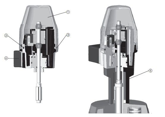
Originalbetriebsanleitung Haftungsausschluss Die technischen Daten sind unverbindlich. Sie gelten nicht als zugesicherte Eigenschaften oder als Beschaffenheits- oder Haltbarkeitsgarantien. Änderungen vorbehalten. Es gelten unsere Allgemeinen Verkaufsbedingungen. Betriebsanleitung beachten Die Betriebsanleitung ist Teil des Produkts und ein wichtiger Baustein im Sicherheitskonzept. Betriebsanleitung lesen und befolgen. Betriebsanleitung stets am Produkt verfügbar halten. Betriebsanleitung an alle nachfolgenden Verwender des Produkts weitergeben.
Inhaltsverzeichnis                                                                                                  Bedienungsanleitung

Inhaltsverzeichnis
Inhaltsverzeichnis............................................................................................................................ 2
1     Sicherheitshinweise................................................................................................................. 3
    1.1       Erläuterung der Symbole ................................................................................................ 3
    1.2       Weitere Symbole und Auszeichnungen .......................................................................... 3
    1.3       Mitgeltende Dokumente .................................................................................................. 3
2      Sicherheit und Verantwortung ................................................................................................ 4
    2.1       Bestimmungsgemässe Verwendung .............................................................................. 4
    2.2       Sicherheitshinweise ......................................................................................................... 4
    2.3       Transport und Lagerung .................................................................................................. 4
3      Aufbau und Funktion ............................................................................................................... 5
    3.1       Aufbau ............................................................................................................................... 5
    3.2       Funktion mit DIASTAR ..................................................................................................... 6
       3.2.1         Zuordnung Adapter zu Antriebsgrösse ................................................................... 6
       3.2.2         Antriebsgrössen DIASTAR DN 15–50 ...................................................................... 6
4      Technische Daten .................................................................................................................... 7
5      Installation ............................................................................................................................... 8
    5.1       Membranventil in Grundausführung............................................................................... 8
    5.2       Membranventil mit Hubbegrenzung ..............................................................................10
    5.3       Justierung ........................................................................................................................12
6      Elektrische Anschlüsse ..........................................................................................................13
    6.1       Gerätestecker belegen ...................................................................................................13
      6.1.1          Schliessfunktion ......................................................................................................13
      6.1.2          Öffnerfunktion ..........................................................................................................13
      6.1.3          Wechslerfunktion ....................................................................................................13
    6.2       Anschlusschaltbilder ......................................................................................................14
7     Ersatzteilliste und Zubehör ....................................................................................................17
8     Entsorgung ..............................................................................................................................18
9     EG Herstellererklärung ..........................................................................................................19

2
Bedienungsanleitung Sicherheitshinweise
1 Sicherheitshinweise
1.1 Erläuterung der Symbole
In dieser Anleitung werden Warnhinweise verwendet, um Sie vor Tod, Verletzungen oder vor
Sachschäden zu warnen. Lesen und beachten Sie diese Warnhinweise immer!
Warnsymbol Bedeutung
Unmittelbar drohende Gefahr!
Bei Nichtbeachtung drohen Ihnen Tod oder schwerste Verletzungen.
GEFAHR Massnahmen, um die Gefahr zu vermeiden.
Möglicherweise drohende Gefahr!
Bei Nichtbeachtung drohen Ihnen schwere Verletzungen.
WARNUNG Massnahmen, um die Gefahr zu vermeiden.
Gefährliche Situation!
Bei Nichtbeachtung drohen leichte Verletzungen.
VORSICHT Massnahmen, um die Gefahr zu vermeiden.
Gefährliche Situation!
ACHTUNG Bei Nichtbeachtung drohen Sachschäden.
Massnahmen, um die Gefahr zu vermeiden.
1.2 Weitere Symbole und Auszeichnungen
Symbol Bedeutung
Hinweise: Enthalten besonders wichtige Informationen zum
Verständnis.
Handlungsaufforderung: Hier müssen Sie etwas tun.
Handlungsaufforderung in einer Handlungsabfolge: Hier müssen Sie
1. etwas tun.
1.3 Mitgeltende Dokumente
Georg Fischer Planungsgrundlagen Industrie
Diese Unterlagen sind über die Vertretung von GF Piping Systems oder unter www.gfps.com
erhältlich.
3Sicherheit und Verantwortung Bedienungsanleitung 2 Sicherheit und Verantwortung 2.1 Bestimmungsgemässe Verwendung Der elektrische Rückmelder dient zur Signalisierung der Ventilstellung von Georg Fischer Membranventilen Typ DIASTAR. Der Rückmelder ist direkt auf das Membranventil Typ DIASTAR aufschraubbar. Der elektrische Rückmelder ist für folgende Dimensionen bestimmt: Typ ER 52: DN 15–50 Typ ER 53: DN 65–150 2.2 Sicherheitshinweise Arbeiten am Rückmelder dürfen nur durchgeführt werden, wenn derselbe von der Speisespannung abgetrennt ist. Arbeiten am Rückmelder dürfen nur von autorisiertem Fachpersonal durchgeführt werden. Produkt nur in technisch einwandfreiem Zustand benutzen und Sicherheitshinweise unbedingt beachten. Komplette Dokumentation in der Nähe des Produkts aufbewahren. Allgemein anerkannte Unfallverhütungsvorschriften beachten. Produkt nur bestimmungsgemäss verwenden, siehe bestimmungsgemässe Verwendung. Für Schäden durch nicht bestimmungsgemässen Gebrauch haftet allein der Benutzer. Nur die in dieser Anleitung aufgeführten Abmessungen und Werkstoffe verwenden. Andere Materialien nur nach Rücksprache mit dem Kundendienst von GF Piping Systems verwenden. Nur Original-Ersatzteile und -Betriebsstoffe von GF Piping Systems verwenden. Produkt auf äusserlich erkennbare Schäden und Mängel überprüfen. Schäden und Mängel sofort beheben lassen. Personal regelmässig in allen zutreffenden Fragen der örtlich geltenden Vorschriften für Arbeitssicherheit, Umweltschutz vor allem für druckführende Rohrleitungen unterweisen. Abweichungen vom Betriebsverhalten sofort dem Verantwortlichen melden. Alle Arbeiten sicherheitsbewusst durchführen. 2.3 Transport und Lagerung Produkt vor Staub, Schmutz, Feuchtigkeit sowie Wärme- und UV-Strahlung schützen. Sicherstellen, dass Produkt weder durch mechanische noch durch thermische Einflüsse beschädigt ist. Produkt vor Montage auf Transportschäden untersuchen. 4
Bedienungsanleitung Aufbau und Funktion
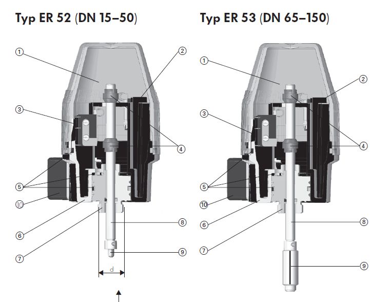
3 Aufbau und Funktion
3.1 Aufbau
1 2 1
2
3 3
4 4
5 5
10 10
8 6 8
6
9 7
7 d* 9
*Durchmesser d, siehe Tabelle 4.2.1
„Zuordnung Adapter zu Antriebsgrösse“
1 Haube SAN 6 Gehäuse PP
2 Mikroschalter «Zu» 7 Sockel Messing
3 Mikroschalter «Auf» 8 Spindel ST Rostfrei
4 Nocken PA 9 Anschlussstück ST Rostfrei
5 O-Ringe NBR 10 Gerätestecker 3P + E / DIN 43650
5Aufbau und Funktion Bedienungsanleitung
3.2 Funktion mit DIASTAR
3.2.1 Zuordnung Adapter zu Antriebsgrösse
d 12 mm 16 mm 16 mm 16 mm
Antriebsgrösse 1/2 3 4 5
benötigte
Adapter
Sockel Messing
3.2.2 Antriebsgrössen DIASTAR DN 15–50
D
Grösse (PP-GF)
mm
1 68
2 96
3 120
4 150
5 180
Dimension Grösse
Typ DIASTAR Ten DIASTAR TenPlus DIASTAR Sixteen
Funktion FC/DA/FO FC/DA/FO FC DA/FO
DN 15 1 2 2 1
DN 20 2 2 2 2
DN 25 2 3 3 2
DN 32 3 4 4 3
DN 40 4 5 5 4
DN 50 4 5 5 4
6Bedienungsanleitung Technische Daten
4 Technische Daten
Schaltleistung
Typ Schaltertyp
ER 52 ER 53
-1 Mikroschalter AgNi 250 V~/ 6 A 250 V~/ 10 A
Mikroschalter mit
-2 4 – 30 V= / 1-100 mA 4 – 30 V= / 1-100 mA
Goldkontakt Au
-3 Induktiv-Schalter NPN 10 – 30 V= / 0.1 A 9.6 – 55 V= / 0.2 A
-4 Induktiv-Schalter PNP 10 – 30 V= / 0.1 A 9.6 – 55 V= / 0.2 A
-5 Induktiv-Schalter Namur 8 V= 8 V=
-6 Mikroschalter Eexd 250 V~/ 5 A 250 V~/ 5 A
= DC
~ AC
Schutzart Gehäuse: IP 65
7Installation Bedienungsanleitung 5 Installation 5.1 Membranventil in Grundausführung 1. Ventil mit Steuerdruck in Stellung «Auf» bringen (FC, DA) 2. Anzeigekappe 1 und Anzeigestift demontieren. Dabei Linksgewinde des Anzeigestifts beachten. 3. Schraube 2 am elektrischen Rückmelder lösen. 4. Transparente Schutzhaube 3 abschrauben. 8
Bedienungsanleitung                                                           Installation

5. Obere Nocke 5 abziehen.
6. Gewindestift 4 lösen.
7. Sockel 6 mit Spindel 7 aus Gehäuse ziehen.
8. Bei Typ ER 52:
       -   Komplette Spindel mit entsprechendem Anschlussstück ergänzen.
       -   Sockel um 180° drehen.
9. Sockel 6 mit Schraubenschlüssel in Stellantrieb schrauben
10. Spindel 7 mit Innensechskantschlüssel in Spindelmutter des Stellantriebes schrauben.
    Dabei Linksgewinde beachten.
11. Gehäuse auf Sockel 6 schieben:
       -   Dabei Gehäuse so positionieren, dass sich der elektrische Anschluss in der
           gewünschten Stellung befindet.
       -   Gewindestift 4 festziehen.
12. Obere Nocke 5 auf Spindel 7 schieben.
13. Rückmelder anschliessen, siehe Kapitel 7 „Elektrische Anschlüsse“.

                                                                                             9
Installation Bedienungsanleitung
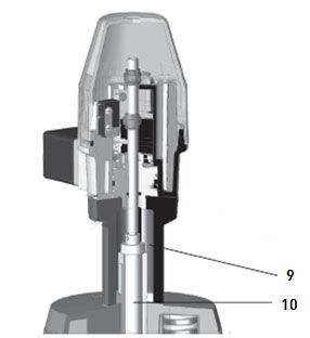
5.2 Membranventil mit Hubbegrenzung
1. Ventil mit Steuerdruck in Stellung «Auf» bringen (FC, DA)
2. Anzeigekappe 1 demontieren.
3. Adapter 9 auf Sicherungsmutter am Stellantrieb schrauben.
4. Bei ER 53:
- Anzeigestift demontieren. Dabei Linksgewinde des Anzeigestifts beachten.
- Verbindungsstück 10 in Anschlussstück schrauben
10Bedienungsanleitung Installation
5. Schraube 2 am elektrischen Rückmelder lösen.
6. Transparente Schutzhaube 3 abschrauben.
7. Obere Nocke 5 abziehen.
8. Gewindestift 4 lösen.
9. Sockel 6 mit Spindel 7 aus Gehäuse ziehen.
10. Sockel 6 mit Schraubenschlüssel in Adapter schrauben.
11. Spindel 7 mit Innensechskantschlüssel in Spindelmutter des Stellantriebes schrauben.
Dabei Linksgewinde beachten.
12. Gehäuse auf Sockel 6 schieben:
- Dabei Gehäuse so positionieren, dass sich der elektrische Anschluss in der
gewünschten Stellung befindet.
- Gewindestift 4 festziehen.
13. Obere Nocke 5 auf Spindel 7 schieben.
14. Rückmelder anschliessen, siehe Kapitel 7 „Elektrische Anschlüsse“.
11Installation Bedienungsanleitung
5.3 Justierung
2
8
7
1
1. Obere Nocke 2 und untere Nocke 7 bündig an Justierplatte 8 schieben
2. Ventil je einmal in «Auf»- und einmal in «Zu»-Position bringen.
Die Nocken werden dadurch korrekt eingestellt.
3. Transparente Haube auf Gehäuse schrauben und mit Schraube 1 arretieren.
12Bedienungsanleitung Elektrische Anschlüsse
6 Elektrische Anschlüsse
6.1 Gerätestecker belegen
6.1.1 Schliessfunktion
Rückmelders mit dem Gerätestecker anschliessen, Anschlussschaltbilder siehe Kapitel
7.2
Anschluss Funktion
1 Schliesser für «AUF»-Position
2 Schliesser für «ZU»-Position
3 Speisung für beide Mikroschalter
6.1.2 Öffnerfunktion
Anschlüsse an den Mikroschaltern umlöten, Anschlussschaltbilder siehe
Kapitel 7.2
Anschluss Nr. 2 belegen.
6.1.3 Wechslerfunktion
Gerätestecker und interne Verkabelung entfernen.
Kabelverschraubung PG11 montieren.
Mikroschalter mit mehradrigem Kabel direkt auf die Anschlusszungen der Mikroschalter
anschliessen. Anschlussschaltbilder siehe Kapitel 7.2
Steckfahne Mirkoschalter Funktion
1 Speisung
2 Öffnung
4 Schliesser
13Elektrische Anschlüsse Bedienungsanleitung
6.2 Anschlusschaltbilder
Typ Code
ER 52-1 199 190 305
ER 52-2 199 190 306
ER 53-1 199 190 293
ER 53-2 199 190 297
Typ Code
ER 52-3 199 190 307
ER 52-4 199 190 308
14Bedienungsanleitung Elektrische Anschlüsse
Typ Code
ER 53-3 199 190 294
ER 53-4 199 190 295
Typ Code
ER 52-5 199 190 309
15Elektrische Anschlüsse Bedienungsanleitung
Typ Code
ER 53-5 199 190 298
Ausgang O 3 mA / o 1 mA nach DIN 19234
Typ Code
ER 52-6 199 190 405
ER 53-6 199 190 298
16Bedienungsanleitung Ersatzteilliste und Zubehör
7 Ersatzteilliste und Zubehör
Pos. Bezeichnung ER 52-1/2 ER 52-3/4/5 ER 53-1/2/7 ER 53-3/4/5
Haubensatz 198 000 217 198 000 213
1 - Haube
2 - Ring
3 - Schraube
4 Leitungsdose 198 000 214 198 000 216 198 000 214 198 000 216
- Leitungsdose
- Profildichtung
5 Adapter
- 199 190 310
komplett*
Adapter
- Grösse 1 – 2 199 190 387 -
- Grösse 3 199 190 388 -
- Grösse 4 – 5
199 190 389 -
*Für Kombination ER 52/ER 53 / Hubgrenzung / Handnotbetätigung
17Entsorgung Bedienungsanleitung
8 Entsorgung
Vor Entsorgung die einzelnen Materialien nach recycelbaren Stoffen, Normalabfall und
Sonderabfall trennen.
Bei Entsorgung oder Recycling des Produkts, der einzelnen Komponenten und der
Verpackung die örtlichen gesetzlichen Bestimmungen und Verordnungen einhalten.
Länderspezifische Vorschriften, Normen und Richtlinien beachten.
WARNUNG
Teile des Produkts können mit gesundheits- und umweltschädlichen Medien
kontaminiert sein, so dass eine einfache Reinigung nicht ausreichend ist!
Gefahr von Personen- oder Umweltschäden durch diese Medien.
Vor der Entsorgung des Produkts:
auslaufende Medien sammeln und entsprechend der örtlichen Vorschriften
entsorgen. Sicherheitsdatenblatt konsultieren.
eventuelle Medienrückstände im Produkt neutralisieren.
Werkstoffe (Kunststoffe, Metalle, usw.) trennen und diese nach den örtlichen
Vorschriften entsorgen.
Bei Fragen bezüglich der Entsorgung des Produkts wenden Sie sich an Ihre nationale
Vertretung von GF Piping Systems.
18Bedienungsanleitung EG Herstellererklärung
9 EG Herstellererklärung
Der Hersteller GF Piping Systems, 8201 Schaffhausen (Schweiz) erklärt, dass der elektrische
Rückmelder
Typ: ER 52 / ER 53
Varianten: ER 52-1, ER 52-2, ER 52-3, ER 52-4, ER 52-5, ER 52-6
ER 53-1, ER 53-2, ER 53-3, ER 53-4, ER 53-5, ER 53-6
Artikelnummern: 199 190 305, 199 190 306, 199 190 307, 199 190 308,
199 190 309, 199 190 405, 199 190 293, 199 190 297,
199 190 294, 199 190 295, 199 190 296, 199 190 298,
konform ist mit den einschlägigen Bestimmungen der Maschinenrichtlinie (2006/42/EC).
Die unvollständige Maschine entspricht weiterhin allen Bestimmungen der Richtlinie
Elektromagnetische Verträglichkeit (2004/108/EG)
Die Inbetriebnahme ist solange untersagt, bis sichergestellt wurde, dass die gesamte
Maschine, in die die o. a. unvollständige Maschine eingebaut werden soll, den Bestimmungen
der Maschinenrichtlinie 2006/42/EG entspricht.
Schaffhausen, den 31.01.2019
Bastian Lübke
Head of global RnD
19Translation of the original instructions Disclaimer The technical data are not binding. They neither constitutes expressly warranted characteristics nor guaranteed properties nor a guaranteed durability. They are subject to modification. Our General Terms of Sale apply. Observe instruction manual The instruction manual is part of the product and an important element within the safety concept. Read and observe instruction manual. Always have instruction manual available by the product. Give instruction manual to all subsequent users of the product.
Instruction Manual                                                                                                               Content

Content
Content ............................................................................................................................................21
1      Safety Information ..................................................................................................................22
    1.1       Warnings ..........................................................................................................................22
    1.2       Further symbols and labels............................................................................................22
    1.3       Other related documents................................................................................................22
2      Safety and responsibility ........................................................................................................23
    2.1       Intended use ....................................................................................................................23
    2.2       Safety information ...........................................................................................................23
    2.3       Transport and storage ....................................................................................................23
3      Design and function ................................................................................................................24
    3.1       Design ..............................................................................................................................24
    3.2       Function with DIASTAR ...................................................................................................25
       3.2.1         Allocation of adapter to actuator sizes...................................................................25
       3.2.2         Actuator sizes DIASTAR DN 15–50 .........................................................................25
4      Technical Data ........................................................................................................................26
5      Installation ..............................................................................................................................27
    5.1       Basic Version of the Diaphragm Valve ...........................................................................27
    5.2       Diaphragm Valve with Stroke Limiter ............................................................................29
    5.3       Adjustment ......................................................................................................................31
6      Electrical Connections ...........................................................................................................32
    6.1       Connect unit plug ............................................................................................................32
       6.1.1         Closed function ........................................................................................................32
       6.1.2         Opened function .......................................................................................................32
       6.1.3         Change-over function ..............................................................................................32
    6.2       Wiring Diagrams .............................................................................................................33
7      Disposal ...................................................................................................................................37
8      CE-Declaration .......................................................................................................................38

                                                                                                                                                  21
Safety Information Instruction Manual
1 Safety Information
1.1 Warnings
In this instruction manual, warnings are used, which shall warn you of death, injuries or
material damage. Always read and observe these warnings!
Warning symbol Meaning
Imminent danger!
Non-observance of these warnings can result in death or extremely
severe injuries.
DANGER
Measures to avoid the danger.
Possible imminent danger!
Non-observance of these warnings can result in severe injuries.
WARNING Measures to avoid the danger.
Dangerous situation!
Non-observance of these warnings can result in minor injuries.
CAUTION Measures to avoid the danger.
Dangerous situation!
CAUTION Non-observance of these warnings can result in material damage.
Measures to avoid the danger.
1.2 Further symbols and labels
Symbol Meaning
Notes: Especially important information for comprehension included.
Call for action: Here, you have to do something.
1. Call for action in a certain order: Here, you have to do something.
1.3 Other related documents
Georg Fischer planning fundamentals industry
These documents can be obtained via the agency of GF Piping Systems or under
www.gfps.com.
22Instruction Manual Safety and responsibility
2 Safety and responsibility
2.1 Intended use
The Electrical Position Indicator is used to indicate the valve position of Georg Fischer
Diaphragm Valves Type DIASTAR. The Position Indicator can be screwed directly onto
the Diaphragm Valve Type DIASTAR.
The Electrical Position Indicator is intended for following dimensions:
Type ER 52: DN 15–50
Type ER 53: DN 65–150
2.2 Safety information
The position indicator must always be disconnected from the mains before any work is
done on it.
Only trained, authorized personnel may carry out any work on the position indicator.
The product must only be used in technically perfect condition, and it is essential to
observe the safety information.
Store complete documentation close to the product.
Observe generally accepted accident prevention regulations.
Only use product as intended, see intended use. The user is solely liable for damages
caused by non-intended use.
Only use the dimensions and materials listed in this manual. Only use other materials
upon consultation with the customer service of GF Piping Systems.
Only use original spare parts and materials by GF Piping Systems.
Check product for externally apparent damages and defects. Immediately remedy all
damages and defects.
Regularly train personnel on all questions pertaining to the locally accepted regulations
on occupational safety and environmental protection, especially on pressure-retaining
pipelines.
Be familiar with, understand and observe instruction manual and the notes contained
within.
Inform the responsible person about any discrepancies from the operational behaviour.
All works must be carried out safety-consciously.
2.3 Transport and storage
Protect product from dust, dirt, dampness as well as thermal and UV radiation.
Make sure that the product has not been damaged neither by mechanical nor thermal
influences.
Check product for transport damages prior to the installation.
23Design and function Instruction Manual
3 Design and function
3.1 Design
1 2 1
2
3 3
4 4
5 5
10 10
8 6 8
6
9 7
7 d* 9
*Diameter d, see table 4.2.1
„Allocation of adapter to actuator sizes“
1 Cover SAN 6 Housing PP
2 Microswitch «closed» 7 Brass base
3 Microswitch «open» 8 Spindle of stainless steel
4 Cam PA 9 Connecting piece of stainless steel
5 O-rings NBR 10 Unit plug 3P + E / DIN 43650
24Instruction Manual Design and function
3.2 Function with DIASTAR
3.2.1 Allocation of adapter to actuator sizes
d 12 mm 16 mm 16 mm 16 mm
Actuator size 1/2 3 4 5
Required
adapter
Brass base
3.2.2 Actuator sizes DIASTAR DN 15–50
D
Size (PP-GF)
mm
1 68
2 96
3 120
4 150
5 180
Dimension Size
Type DIASTAR Ten DIASTAR TenPlus DIASTAR Sixteen
Function FC/DA/FO FC/DA/FO FC DA/FO
DN 15 1 2 2 1
DN 20 2 2 2 2
DN 25 2 3 3 2
DN 32 3 4 4 3
DN 40 4 5 5 4
DN 50 4 5 5 4
25Technical Data Instruction Manual
4 Technical Data
Switching capacity
Type Type of switch
ER 52 ER 53
-1 Microswitch AgNi 250 V~/ 6 A 250 V~/ 10 A
Microswitch with gold-plated
-2 4 – 30 V= / 1-100 mA 4 – 30 V= / 1-100 mA
Au
-3 Inductive switch NPN 10 – 30 V= / 0.1 A 9.6 – 55 V= / 0.2 A
-4 Inductive switch PNP 10 – 30 V= / 0.1 A 9.6 – 55 V= / 0.2 A
-5 Inductive switch Namur 8 V= 8 V=
-6 Mikroswitch Eexd 250 V~/ 5 A 250 V~/ 5 A
= DC
~ AC
Protection rating housing: IP 65
26Instruction Manual Installation
5 Installation
5.1 Basic Version of the Diaphragm Valve
1. Put valve in the «open» position using control pressure (FC, DA)
2. Remove indicator cap 1 and indicator pin (Attention: indicator pin has left thread)
3. Loosen screw 2 on the electrical position indicator.
4. Unscrew the transparent protective cover 3.
27Installation Instruction Manual
5. Pull upper cam 5 off.
6. Loosen threaded bolt 4.
7. Pull the base with spindle 6 out of the housing 7.
8. Type ER 52:
- Complete spindle with respective connecting piece
- Turn brass by 180°.
9. Screw the base 6 with a wrench in the actuator.
10. Screw the spindle 7 with an Allen key into the spindle nut of the actuator (Attention: left
thread).
11. Place housing on base 6:
- Make sure that the electrical connection is in the desired position.
- Secure threaded bolt 4.
12. Put upper cam 5 on the spindle 7.
13. Do electrical connections according to chapter 7 „Electrical Connections“.
28Instruction Manual Installation
5.2 Diaphragm Valve with Stroke Limiter
1. Put valve in the «open» position using control pressure (FC, DA))
2. Remove indicator cap 1.
3. Screw the adapter 9 onto the locknut of the actuator.
4. Type ER 53:
- Remove indicator cap. (Attention: indicator pin has left thread.)
- Screw the intermediate piece 10 into the connecting piece.
29Installation Instruction Manual
5. Loosen the screw 2 on the electrical position indicator.
6. Unscrew the transparent, protective cover 3.
7. Pull upper cam 5 off.
8. Loosen the threaded bolt 4
9. Pull the base 6 with the spindle 7 out of the housing.
10. Screw the base 6 with a wrench into the adapter.
11. Screw the spindle 7 with an Allen key into the spindle nut of the actuator (Attention: left
thread).
12. Place housing on base 6:
- Make sure that the electrical connection is in the desired position.
- Secure threaded bolt 4.
13. Put upper cam 5 on the spindle 7.
14. Do electrical connections according to chapter 7 „Electrical Connections“.
30Instruction Manual Installation
5.3 Adjustment
2
8
7
1
1. Slide the upper cam 2 and the lower cam 7 flush against the adjustment plate 8.
2. Put the valve once in the «open» and once in the «closed» position The cams are hereby
correctly adjusted.
3. Screw the transparent cover back on the housing and tighten with the screw 1.
31Electrical Connections Instruction Manual 6 Electrical Connections 6.1 Connect unit plug 6.1.1 Closed function Connect the position indicator with the unit plug, wiring diagrams see chapter 7.2 Connect Function 1 Normally open contact for «OPEN» position 2 Normally open contact for «CLOSED» position 3 Power supply for both microswitches 6.1.2 Opened function Change connection No 4 on the microswitch, wiring diagrams see chapter 7.2 Connect No 2. 6.1.3 Change-over function Remove the unit plug and the internal wiring Install a PG11 cable gland. Connect multiple wires directly to the microswitch connector lug. Plat pin microswitches Function 1 Power supply 2 Normally closed 4 Normally open 32
Instruction Manual           Electrical Connections

6.2 Wiring Diagrams

                      Type         Code

                      ER 52-1      199 190 305

                      ER 52-2      199 190 306

                      ER 53-1      199 190 293

                      ER 53-2      199 190 297

                      Type         Code

                      ER 52-3      199 190 307

                      ER 52-4      199 190 308

                                                 33
Electrical Connections Instruction Manual
Type Code
ER 53-3 199 190 294
ER 53-4 199 190 295
Type Code
ER 52-5 199 190 309
34Instruction Manual Electrical Connections
Type Code
ER 53-5 199 190 298
Output O 3 mA / o 1 mA to DIN 19234
Type Code
ER 52-6 199 190 405
ER 53-6 199 190 298
35Electrical Connections Instruction Manual
Spare parts and accessories
Pos. Article ER 52-1/2 ER 52-3/4/5 ER 53-1/2/7 ER 53-3/4/5
Cover set 198 000 217 198 000 213
1 - Cover
2 - O-ring
3 - Screw
4 Unit plug 198 000 214 198 000 216 198 000 214 198 000 216
- Cable socket
- Profile washer
5 Adapter
- 199 190 310
complete*
Adapter
- Size 1 – 2 199 190 387 -
- Size 3 199 190 388 -
- Size 4 – 5
199 190 389 -
*For combination ER 52/ER 53 / Hubgrenzung / Handnotbetätigung
36Instruction Manual Disposal
7 Disposal
Before disposing of the different material, separate it by recyclables, normal waste and
special waste.
Comply with local legal regulations and provisions when recycling or disposing of the
product, the individual components and the packaging.
Comply with National regulations, standards and directives.
WARNING
Parts of the product may be contaminated with media that are harmful
for the health and the environment. Therefore, a simple cleaning is not
sufficient!
Danger of personal injury and damage to the environment caused by those media.
Prior to disposing of the product:
collect leaking material and dispose of according to the local requirements.
Consult safety data sheet.
neutralise possible media residue in the product.
Separate materials (plastics, metals etc.) and dispose of according to the local
requirements.
If you have questions regarding the disposal of your product, please contact your national GF
Piping Systems representative.
37CE-Declaration Instruction Manual
8 CE-Declaration
The manufacturer, GF Piping Systems, CH-8201 Schaffhausen (Switzerland) declares, that the
Diaphragm valves Type DIASTAR
Herewith we declare that
Electrical Position Indicator:
Type: ER 52 / ER 53
Variants: ER 52-1, ER 52-2, ER 52-3, ER 52-4, ER 52-5, ER 52-6
ER 53-1, ER 53-2, ER 53-3, ER 53-4, ER 53-5, ER 53-6
Code: 199 190 305, 199 190 306, 199 190 307, 199 190 308,
199 190 309, 199 190 405, 199 190 293, 199 190 297,
199 190 294, 199 190 295, 199 190 296, 199 190 298,
is in conformity with the relevant provision of the Machinery Directive 2006/42/EC.
is in conformity with the provisions of the following other EC-Directives:
- Electromagnetic Compatibility (EMC) Directive 2004/108/EC
It is forbidden to put this partly completed machine into operation until it has been
ascertained that the complete machine in which this machine is to be installed meets the
provisions of the EC directive 2006/42/EC (Machine directive) .
Schaffhausen, den 31.01.2019
Bastian Lübke
Head of global RnD
38Mode d'emploi original Clause de non-responsabilité Les données techniques sont non contraignantes. Elles ne constituent pas des propriétés assurées, ni des garanties de qualité ou de durabilité. Sous réserve de modifications. Nos Conditions générales de vente sont d'application. Respecter le mode d’emploi Le mode d'emploi fait partie intégrante du produit et est un élément important du concept de sécurité. Lire et respecter le mode d'emploi. Toujours conserver le mode d'emploi avec le produit. Transmettre de mode d'emploi à tous les utilisateurs ultérieurs du produit.
Table des matières                                                                                                Manuel d’instruction

Table des matières
Table des matières .........................................................................................................................40
1     Informations générales ..........................................................................................................41
    1.1      Avertissements................................................................................................................41
    1.2      Autres symboles et marques particulières ...................................................................41
    1.3      Documents applicables ..................................................................................................41
2     Sécurité et responsabilité ......................................................................................................42
    2.1      Utilisation conforme .......................................................................................................42
    2.2      Instructions de sécurité ..................................................................................................42
    2.3      Transport et stockage .....................................................................................................42
3     Structure et caractéristique ..................................................................................................43
    3.1      Structure ..........................................................................................................................43
    3.2      Fonction avec DIASTAR...................................................................................................44
      3.2.1         Répartition de l'adaptateur à grandeurs du servomécanisme .............................44
      3.2.2         Grandeurs du servomécanisme .............................................................................44
4     Caractéristiques techniques ..................................................................................................45
5     Installation ..............................................................................................................................46
    5.1      Robinet à membrane en exécution de base ..................................................................46
    5.2      Robinet à membrane avec limiteur de course ..............................................................48
    5.3      Ajustage ...........................................................................................................................50
6     Raccordements électriques ...................................................................................................51
    6.1      Utiliser raccordement .....................................................................................................51
      6.1.1         Fonction de la fermeture ........................................................................................51
      6.1.2         Fonction de contact de repos .................................................................................51
      6.1.3         Fonction inverseur...................................................................................................51
    6.2      Schémas de raccordement ............................................................................................52
7     Pièces de rechange et accessoires .......................................................................................55
8     Elimination ..............................................................................................................................56
9     CE-Déclaration d’incorporation de quasi-machines ............................................................57

40
Manuel d’instruction Informations générales
1 Informations générales
1.1 Avertissements
La présente instruction utilise des avertissements destinés à vous prévenir des dommages
corporels et matériels potentiels. Veuillez lire et toujours observer ces avertissements!
Symbole Signification
d’avertissement
Menace de danger imminente!
En cas de non-respect, vous risquez la mort ou de graves blessures.
DANGER Mesure afin d'éviter le danger.
Menace de danger potentielle!
En cas de non-respect, vous risquez de graves blessures.
AVERTISSEMENT Mesure afin d'éviter le danger.
Situation dangereuse!
En cas de non-respect, vous risquez de légères blessures.
PRECAUTION Mesure afin d'éviter le danger.
Situation dangereuse!
ATTENTION En cas de non-respect, il existe un risque de dégâts matériels.
Mesure afin d'éviter le danger.
1.2 Autres symboles et marques particulières
Symbole Signification
Remarques: contiennent des informations importantes pour la
compréhension.
Demande d'action : vous devez faire quelque chose.
1. Demande d'action dans une procédure : vous devez faire quelque chose.
1.3 Documents applicables
Georg Fischer les bases de planification industrie
Vous recevrez les bases de planification évoquées dans le texte par le biais de votre société
de vente compétente ainsi que dans Internet sous www.piping.georgfischer.com.
41Sécurité et responsabilité Manuel d’instruction 2 Sécurité et responsabilité 2.1 Utilisation conforme L’indicateur électrique sert à la signalisation des positions d’ouverture et de fermeture du robinet à membrane George Fischer de type DIASTAR. L’indicateur électrique de position se fixe directement sur le robinet à membrane de type DIASTAR. Type ER 52: DN 15–50 Type ER 53: DN 65–150 2.2 Instructions de sécurité Utiliser le produit conformément aux dispositions uniquement, voir Utilisation conforme Ne pas utiliser un produit s‘il est endommagé ou défectueux. Isoler immédiatement tout produit endommagé. S‘assurer que le système de tuyauterie est posé correctement et qu‘il est contrôlé régulièrement. Les produits et accessoires doivent uniquement être montés par des personnes qui disposent de la formation, des connaissances ou de l‘expérience nécessaires. Informer régulièrement le personnel de toutes les questions relatives aux dispositions locales applicables en matière de sécurité du travail et de protection de l‘environnement, notamment pour les canalisations sous pression. Il faut débrancher l’indicateur de position de la tension réseau lorsqu’il a lieu d’y exécuter un travail. Les interventions sur l’indicateur de position ne doivent être effectuées que par des personnes qualifiées et autorisées. 2.3 Transport et stockage Protéger le produit de la poussière, de la saleté, de l‘humidité ainsi que des rayonnements UV et solaires. S‘assurer que le produit n‘est pas détérioré par des influences thermiques ou mécaniques. Contrôler le produit avant le montage afin de détecter d‘éventuels dégâts de transport. 42
Manuel d’instruction                                                  Structure et caractéristique

3 Structure et caractéristique
3.1 Structure

      1                                  2        1

                                                                                         2

      3                                           3

                                         4                                               4

      5                                           5

   10                                          10
                                         8        6                                      8
      6
                                         9        7
      7                    d*                                                            9

                       *Diameter d, see table 4.2.1
                       „Allocation of adapter to actuator sizes“

  1       Capot transparent en SAN            6       Boîtier en PP

  2       Microcontacteur «FERME»             7       Socle en laiton

  3       Microcontacteur «OUVERT»            8       Tige de commande en acier inoxydable

                                                      Pièce de raccordement en acier
  4       Came de commande en PA              9
                                                      inoxydable

  5       Joints toriques en NBR             10       Connecteur 3P + T / DIN 43650

                                                                                               43
Structure et caractéristique Manuel d’instruction
3.2 Fonction avec DIASTAR
3.2.1 Répartition de l'adaptateur à grandeurs du servomécanisme
d 12 mm 16 mm 16 mm 16 mm
grandeurs du
1/2 3 4 5
servomécanisme
adaptateur
requis
Socle en laiton
3.2.2 Grandeurs du servomécanisme
D
Grandeur (PP-GF)
mm
1 68
2 96
3 120
4 150
5 180
Dimension Grandeur
Type DIASTAR Ten DIASTAR TenPlus DIASTAR Sixteen
Fonction FC/DA/FO FC/DA/FO FC DA/FO
DN 15 1 2 2 1
DN 20 2 2 2 2
DN 25 2 3 3 2
DN 32 3 4 4 3
DN 40 4 5 5 4
DN 50 4 5 5 4
44Manuel d’instruction Caractéristiques techniques
4 Caractéristiques techniques
Pouvoir de coupure
Type Type d’interrupteur
ER 52 ER 53
-1 Microcontacteur AgNi 250 V~/ 6 A 250 V~/ 10 A
Microcontacteur à contacts
-2 4 – 30 V= / 1-100 mA 4 – 30 V= / 1-100 mA
or Au
-3 Contacteur inductif NPN 10 – 30 V= / 0.1 A 9.6 – 55 V= / 0.2 A
-4 Contacteur inductif PNP 10 – 30 V= / 0.1 A 9.6 – 55 V= / 0.2 A
-5 Contacteur inductif Namur 8 V= 8 V=
-6 Microcontacteur Eexd 250 V~/ 5 A 250 V~/ 5 A
= DC
~ AC
Boîtier: Mode de protection IP 65
45Installation Manuel d’instruction 5 Installation 5.1 Robinet à membrane en exécution de base 1. Mettre le robinet dans la position «OUVERT» au moyen de la pression de commande (FC, DA) 2. Démonter le capot de l’indicateur 1 (attention: la goupille indicatrice est filetée à gauche) 3. Desserrer la vis 2 sur l’indicateur électrique de position. 4. Dévisser le capot de protection 3. 46
Manuel d’instruction                                                          Installation

5. Enlever la came supérieure 5.
6. Dévisser la vis sans tête 4.
7. Sortir du boîtier 6 le socle avec la tige de commande 7.
8. Type ER 52:
   -   Compléter la tige de commande avec la pièce de raccordement
   -   Position le socle de 180°.
9. Visser le socle 6 dans le servomécanisme au moyen d’une clé à écrou.
10. Visser la tige de commande 7 avec une clé six pans mâle dans l’écrou de tige du
    servomécanisme (attention: filetage à gauche).
11. Pousser le boîtier sur le socle 6:
   - Pousser le positionner de telle façon que le connecteur électrique soit placé dans la
   position voulue.
   -   Serrer à bloc la vis sans tête 4.
12. Pousser la came supérieure 5 sur la tige de commande 7.
13. Raccordements électriques selon schémas, voir chapter 7 „ Raccordements électriques“.

                                                                                             47
Installation Manuel d’instruction
5.2 Robinet à membrane avec limiteur de course
1. Mettre le robinet dans la position «OUVERT» au moyen de la pression de commande (FC,
DA)
2. Démonter le capot de l’indicateur 1.
3. Visser l’adaptateur 9 sur l’écrou de sécurité sur le servomécanisme.
4. Type ER 53:
- Démontage de l’indicateur de position (Attention: filetage à gauche).
- Visser la pièce de jonction 10 dans la pièce de raccordement.
48Manuel d’instruction Installation
5. Desserrer la vis 2 sur l’indicateur électrique de position.
6. Dévisser le capot de protection transparent 3.
7. Enlever la came supérieure 5.
8. Dévisser la vis sans tête 4.
9. Sortir du boîtier 6 le socle avec la tige de commande 7.
10. Visser le socle 6 dans l’adaptateur au moyen d’une clé à écrou de 27 mm.
11. Visser la tige de commande 7 avec une clé six pans mâle de 4 mm dans l’écrou de tige du
servomécanisme (attention: filetage à gauche).
12. Pousser le boîtier sur le socle 6:
- Pousser le positionner de telle façon que le connecteur électrique soit placé dans la
position voulue.
- Serrer à bloc la vis sans tête 4.
13. Put upper cam 5 on the spindle 7.
14. Raccordements électriques selon schémas, voir chapter 7 „ Raccordements électriques“.
49Installation Manuel d’instruction
5.3 Ajustage
2
8
7
1
1. Pousser à fleur de la plaque d’ajustage 8 la came supérieure 2 et la came inférieure 7.
2. Mettre le robinet tour à tour dans la position «OUVERT» et dans la position «FERME».
3. Visser le capot transparent sur le boîtier et le bloquer avec la vis 1.
50Manuel d’instruction Raccordements électriques
6 Raccordements électriques
6.1 Utiliser raccordement
6.1.1 Fonction de la fermeture
Le raccordement de l’indicateur électrique ER 53 s’effectue normalement par son
connecteur.
Broche du connecteur Fonction
1 Contact de travail pour position «OUVERT»
2 Contact de travail pour position «FERME»
3 Alimentation pour les deux microcontacteurs
6.1.2 Fonction de contact de repos
Changer les raccordements sur les microcontacteurs.
Utiliser raccordement no 2.
6.1.3 Fonction inverseur
Enlever le connecteur et le câblage interne.
Installer une douille passe-câble PG 11.
Raccorder directement les microcontacteurs par un câble multipolaire sur les lames de
contact des microcontacteurs.
Flat pin microswitch Fonction
1 Alimentation
2 Contact de repos
4 Contact de travail
51Raccordements électriques Manuel d’instruction
6.2 Schémas de raccordement
Typ Code
ER 52-1 199 190 305
ER 52-2 199 190 306
ER 53-1 199 190 293
ER 53-2 199 190 297
Typ Code
ER 52-3 199 190 307
ER 52-4 199 190 308
52Manuel d’instruction Raccordements électriques
Typ Code
ER 53-3 199 190 294
ER 53-4 199 190 295
Typ Code
ER 52-5 199 190 309
53Raccordements électriques Manuel d’instruction
Typ Code
ER 53-5 199 190 298
Sortie O 3 mA / o 1 mA selon DIN ¢9234
Typ Code
ER 52-6 199 190 405
ER 53-6 199 190 298
54Manuel d’instruction Pièces de rechange et accessoires
7 Pièces de rechange et accessoires
Pos. Article ER 52-1/2 ER 52-3/4/5 ER 53-1/2/7 ER 53-3/4/5
Ensemble capot 198 000 217 198 000 213
1 - Capot
2 - Joint torique
3 - Vis à tête
cylindrique
4 Connecteur 198 000 214 198 000 216 198 000 214 198 000 216
- Connecteur
- Joint profilé
5 Adaptateur
- 199 190 310
complet *
Adaptateur
- Grandeur 1 – 2 199 190 387 -
- Grandeur 3 199 190 388 -
- Grandeur 4 – 5
199 190 389 -
*Pour combinaison ER 52/ER 53 / Limiteur de course / commande manuelle de secours
55Elimination Manuel d’instruction
8 Elimination
Avant la mise au rebut, trier les différents matériaux et séparer les matériaux recyclables,
les déchets normaux et les déchets spéciaux.
En cas de mise au rebut ou de recyclage du produit, des composants individuels et de
l'emballage, respecter les dispositions légales et décrets en vigueur.
Respecter les prescriptions, normes et directives nationales spécifiques.
AVERTISSEMENT
Les pièces du produit peuvent être contaminées avec des fluides nocifs
pour la santé et pour l'environnement, de sorte qu'un simple nettoyage
n'est pas suffisant!
Risque de dégâts personnels et environnementaux dû à ces substances.
Avant l'élimination du produit:
Récupérer les fluides qui s'écoulent et les éliminer conformément aux
dispositions locales. Consulter la fiche technique de sécurité..
Neutraliser les éventuels résidus de fluide sur le produit.
Trier les différents matériaux (plastiques, métaux, etc.) et les éliminer
conformément aux dispositions locales.
En cas de questions relatives à la mise au rebut du produit, adressez-vous à la représentation
nationale de GF Piping Systems
56Manuel d’instruction CE-Déclaration d’incorporation de quasi-machines
9 CE-Déclaration d’incorporation de quasi-machines
Le fabricant, GF Piping Systems, CH-8201 Schaffhausen (Suisse) déclare, que les vannes à
membrane de type DIASTAR
Type: ER 52 / ER 53
Versions: ER 52-1, ER 52-2, ER 52-3, ER 52-4, ER 52-5, ER 52-6
ER 53-1, ER 53-2, ER 53-3, ER 53-4, ER 53-5, ER 53-6
Code: 199 190 305, 199 190 306, 199 190 307, 199 190 308,
199 190 309, 199 190 405, 199 190 293, 199 190 297,
199 190 294, 199 190 295, 199 190 296, 199 190 298,
sont en conformité avec les dispositions correspondantes des directives européennes sur
les machines (2006/42/CE).
sont en conformité avec les dispositions des autres directives européennes suivantes:
- directive de compatibilité électromagnétique CEM 2004/108/EG (EMC)
Les produits sonst destinés à être intégrés dans des machines. La mise en service n’est
autorisée qu’après garantie que la machine finale dans laquelle les produits sonst incorporés
est conforme aux dispositions pertinentes à la directive CE relative aux machines
2006/42/EC .
Schaffhausen, le 31.01.2019
Bastian Lübke
Head of global RnD
57Traducción del manual original Obsérvese el manual de instrucciones El manual de instrucciones forma parte del producto y es un elemento importante del concepto de seguridad. Lea y tenga en cuenta el manual de instrucciones. Guarde el manual de instrucciones junto con el producto de manera que esté siempre disponible. Entregue el manual de instrucciones en caso de transmitir el producto a otros usuarios.
Manual de instrucciones                                                                                                        Contenido

Contenido
Contenido ........................................................................................................................................59
1      Acerca de este documento .....................................................................................................60
    1.1       Advertencias e instrucciones de seguridad ...................................................................60
    1.2       Otros símbolos y señalizaciones ....................................................................................60
    1.3       Documentación complementaria ...................................................................................60
2      Seguridad y responsabilidad ..................................................................................................61
    2.1       Uso conforme a su destino .............................................................................................61
    2.2       Advertencias de seguridad .............................................................................................61
    2.3       Transporte y almacenamiento .......................................................................................61
3      Componentes y funcionamiento ............................................................................................62
    3.1       Componentes ..................................................................................................................62
    3.2       Funcionamiento con DIASTAR .......................................................................................63
       3.2.1         Asignación de adaptadores al tamaño del actuador .............................................63
       3.2.2         Tamaños de actuador DIASTAR DN 15–50 ............................................................63
4      Datos técnicos.........................................................................................................................64
5      Instalación ...............................................................................................................................65
    5.1       Válvula de diafragma en ejecución básica .....................................................................65
    5.2       Válvula de diafragma con limitación de carrera ...........................................................67
    5.3       Ajuste ...............................................................................................................................69
6      Conexiones eléctricas ............................................................................................................70
    6.1       Ocupación de conectores del aparato............................................................................70
       6.1.1         Función de cierre.....................................................................................................70
       6.1.2         Función de contacto normalmente cerrado ..........................................................70
       6.1.3         Función de contacto inversor .................................................................................70
    6.2       Esquemas de conexiones ...............................................................................................71
7      Lista de repuestos y accesorios.............................................................................................74
8      Eliminación..............................................................................................................................75
9      Declaración del fabricante .....................................................................................................76

                                                                                                                                                  59
Sie können auch lesen