R 125 RD 125 - Lovibond Water Testing Tintometer Group
←
→
Transkription von Seiteninhalten
Wenn Ihr Browser die Seite nicht korrekt rendert, bitte, lesen Sie den Inhalt der Seite unten
Lovibond® Water Testing
Tintometer® Group

R 125

RD 125
DE   Bedienungsanleitung   ES   Instrucciones

GB   Instruction Manual    IT   Istruzioni d‘uso

FR   Mode d‘emploi

 www.lovibond.com
Konformitätserklärung mit gefordertem Inhalt gemäß EN ISO/IEC 17050-1
                                                               Supplier's declaration of conformity in accordance with EN ISO/IEC 17050-1

                                          EU-Konformitätserklärung / EU-Declaration of Conformity
                                                                        Dokument-Nr. / Monat.Jahr:
                                                                        Document No. / Month.Year:                                 4                         /                                                8.2018
Für das nachfolgend bezeichnete Erzeugnis / For the following mentioned product

              Bezeichnung / Name,
                                                                                                                 CSB - COD Thermoreactor RD 125 - AL 125 , (2)418940
            Modellnummer / Model No.
wird hiermit erklärt, dass es den grundlegenden Anforderungen entspricht, die in den nachfolgend bezeichneten Harmonisierungsrechtsvorschriften festgelegt sind: / it is hereby declared that it
complies with the essential requirements which are determined in the following harmonisation rules:

Richtlinie 2014/30/EU des Europäischen Parlaments und des Rates vom 26. Februar 2014 zur Harmonisierung der Rechtsvorschriften der Mitgliedstaaten
über die elektromagnetische Verträglichkeit .
Directive 2014/30/EU of the European Parliament and of the Council of 26 February 2014 on the harmonisation of the laws of the Member States relating
to electromagnetic compatibility .

Richtlinie 2014/35/EU des Europäischen Parlaments und des Rates vom 26. Februar 2014 zur Harmonisierung der Rechtsvorschriften der Mitgliedstaaten
über die Bereitstellung elektrischer Betriebsmittel zur Verwendung innerhalb bestimmter Spannungsgrenzen auf dem Markt .
Directive 2014/35/EU of the European Parliament and of the Council of 26 February 2014 on the harmonisation of the laws of the Member States relating
to the making available on the market of electrical equipment designed for use within certain voltage limits .
RICHTLINIE 2011/65/EU DES EUROPÄISCHEN PARLAMENTS UND DES RATES vom 8. Juni 2011 zur Beschränkung der Verwendung bestimmter gefährlicher
Stoffe in Elektro- und Elektronikgeräten (Neufassung)
DIRECTIVE 2011/65/EU OF THE EUROPEAN PARLIAMENT AND OF THE COUNCIL of 8 June 2011 on the restriction of the use of certain hazardous
substances in electrical and electronic equipment (recast)
Angabe der einschlägigen harmonisierten Normen, die zugrunde gelegt wurden, oder Angabe der Spezifikationen, für die die Konformität erklärt wird: / Information of relevant harmonised
standards and specifications on which the conformity is based:
                                    Ausgabedatum/
              Fundstelle / Reference                                                                                                                                Titel / Title
                                        Edition
Harmosisierte Normen / Harmonised Standards
                                                                                              Elektrische Mess-, Steuer-, Regel- und Laborgeräte - EMV-Anforderungen - Teil 1: Allgemeine
DIN EN 61326-1                                                         2013-07
                                                                                              Anforderungen (IEC 61326-1:2012)
                                                                                              Sicherheitsbestimmungen für elektrische Mess-, Steuer-, Regel- und Laborgeräte - Teil 1:
DIN EN 61010-1                                                         2011-07
                                                                                              Allgemeine Anforderungen (IEC 61010-1:2010 + Cor. :2011)

                                                                                              Sicherheitsbestimmungen für elektrische Mess-, Steuer-, Regel- und Laborgeräte - Teil 2-010:
EN 61010-2-010                                                            2014
                                                                                              Besondere Anforderungen an Laborgeräte für das Erhitzen von Stoffen (IEC 61010-2-010:2014)

                                                                                              Technische Dokumentation zur Beurteilung von Elektro- und Elektronikgeräten hinsichtlich der
DIN EN 50581                                                           2013-02
                                                                                              Beschränkung gefährlicher Stoffe; Deutsche Fassung EN 50581:2012

Weitere angewandte technische Spezifikationen (nicht im EU-Amtsblatt veröffentlicht) / Further applied technical specifications (not published in the Official Journal of the EU)

Diese Erklärung wird verantwortlich für den Hersteller oder seinem Bevollmächtigten / This declaration is made for and on behalf of the manufacturer or his representatives

Name:                                    Tintometer GmbH
Anschrift / Address:                     Schleefstr. 8-12, 44287 Dortmund, Germany
abgegeben durch / declared by

Name, Vorname / First name:                                     Dr. Grabert, Elmar
Funktion / Function:                                            Technische Leitung / Director Technology
Bevollmächtigte Person im Sinne des Anhangs II Nr. 1. A. Nr. 2, 2006/42/EG für die Zusammenstellung der technischen Unterlagen / Authorized person for compilation of
technical documents on behalf of Annex II No. 1. A. No. 2, 2006/42/EC:

Name:                                    Corinna Meier
Anschrift / Address:                     c/o Tintometer GmbH, Schleefstr. 8-12, 44287 Dortmund

Dortmund                                 21.8.2018

     Ort, Datum / Place and date of issue                                                                                                Rechtsgültige Unterschrift / Authorized signature

Diese Erklärung bescheinigt die Übereinstimmung mit den so genannten Harmonisierungsrechtsvorschriften, beinhaltet jedoch keine Zusicherung von Eigenschaften. / This declaration certifies
the conformity to the specified directives but contains no assurance of properties.
Zusatzangaben / Additional details:
Diese Erklärung gilt für alle Exemplare, die nach den entsprechenden Fertigungszeichnungen - die Bestandteil der technischen Unterlagen sind - hergestellt werden. Weitere Angaben über die Einhaltung obiger Fundstellen enthält die beigefügte
Konformitätsaussage unterstützende Begleitdokumentation. / This statement is valid for all copies which were manufactured in accordance with the technical drawings which are part of the technical documentation. More details about compliance of the
above mentioned references includes the supporting documentation.

Doc file:                                CSB - COD Thermoreactor RD 125 - AL 125 DokNr_4__8_2018

2                                                                                                                                                                             RD 125_7b 01/2020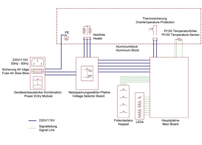
Inhaltsverzeichnis
1.       RD 125  . . . . . . . . . . . . . . . . . . . . . . . . . . . . . . . . . . . . . . . . . . . . . . . . . .    4
1.1      Einleitung . . . . . . . . . . . . . . . . . . . . . . . . . . . . . . . . . . . . . . . . . . . . . . . . .   4
1.1.1    Bestimmungsgemäßer Gebrauch . . . . . . . . . . . . . . . . . . . . . . . . . . . . . . .                      4
1.1.2    Verwendung von Symbolen . . . . . . . . . . . . . . . . . . . . . . . . . . . . . . . . . . .                  4
1.2      Wichtige Hinweise . . . . . . . . . . . . . . . . . . . . . . . . . . . . . . . . . . . . . . . . . .          5
1.3      Auspacken . . . . . . . . . . . . . . . . . . . . . . . . . . . . . . . . . . . . . . . . . . . . . . . .      6
1.4      Anschließen . . . . . . . . . . . . . . . . . . . . . . . . . . . . . . . . . . . . . . . . . . . . . . .      6
1.5      Bedienelemente . . . . . . . . . . . . . . . . . . . . . . . . . . . . . . . . . . . . . . . . . . . .         7
1.6      Funktion der Bedienelemente . . . . . . . . . . . . . . . . . . . . . . . . . . . . . . . . . .                7
2.       Bedienung  . . . . . . . . . . . . . . . . . . . . . . . . . . . . . . . . . . . . . . . . . . . . . . . 8
3.       Beeper  . . . . . . . . . . . . . . . . . . . . . . . . . . . . . . . . . . . . . . . . . . . . . . . . . . 8
4.       Bedienkonzept  . . . . . . . . . . . . . . . . . . . . . . . . . . . . . . . . . . . . . . . . . . . 9
5.       Wartung  . . . . . . . . . . . . . . . . . . . . . . . . . . . . . . . . . . . . . . . . . . . . . . . 10
6.       Reinigung  . . . . . . . . . . . . . . . . . . . . . . . . . . . . . . . . . . . . . . . . . . . . . . 10
7.       Technische Daten  . . . . . . . . . . . . . . . . . . . . . . . . . . . . . . . . . . . . . . . . 10
8.       Blockschaltbild  . . . . . . . . . . . . . . . . . . . . . . . . . . . . . . . . . . . . . . . . . . 11
9.       LED-Fehlercode  . . . . . . . . . . . . . . . . . . . . . . . . . . . . . . . . . . . . . . . . . . 12

                                                Wichtige Information
      Um die Qualität unserer Umwelt zu erhalten, beschützen und zu verbessern
             Entsorgung von elektronischen Geräten in der Europäischen Union
     Aufgrund der Europäischen Verordnung 2012/19/EU darf Ihr elektronisches Gerät nicht
                            mit dem normalen Hausmüll entsorgt werden!
      Tintometer GmbH entsorgt ihr elektrisches Gerät auf eine professionelle und für die
              Umwelt verantwortungsvolle Weise. Dieser Service ist, die Transportkosten
             nicht inbegriffen, kostenlos. Dieser Service gilt ausschließlich für elektrische
            Geräte die nach dem 13.08.2005 erworben wurden. Senden Sie Ihre zu entsor-
                       genden Tintometer Geräte frei Haus an Ihren Lieferanten.

     RD 125_7b 01/2020                                                                                                      3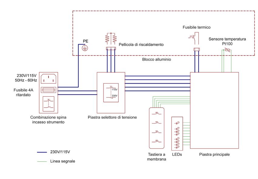
1.      RD 125
    1.1     Einleitung
            Bitte Bedienungsanleitung lesen, ehe Sie das Gerät in Betrieb nehmen. Der Hersteller
            übernimmt keine Haftung bei nicht sachgemäßer Benutzung des Gerätes und
            Nichteinhaltung der Bedienungsvorschriften.

    1.1.1   Bestimmungsgemäßer Gebrauch
            Der Thermoreaktor darf ausschließlich zum Erhitzen von verschlossenen 16-mm-Ø
            Küvettenteströhrchen verwendet werden.
            Grundsätzlich ist beim Starten des Heizvorgangs und während der Heizperiode die
            Schutzhaube geschlossen zu halten.
            Die zu wählende Temperatur und das entsprechende Zeitintervall sind Küvettentest-
            abhängig und sind in der zu den Küvettentest gehörenden Analysenvorschrift ange-
            geben. Auf die Einhaltung dieser Angaben ist unbedingt zu achten.
            Die am Gerät angebrachten Schilder weisen auf die Gefahren hin, denen der
            Benutzer beim Betrieb oder bei Wartungsarbeiten ausgesetzt ist. Die Etiketten dürfen
            nicht entfernt werden und müssen, wenn sie unleserlich geworden sind, durch neue
            ersetzt werden.

    1.1.2   Verwendung von Symbolen
            In dieser Anleitung wurden folgende Symbole verwendet, um auf eine mögliche
            Personengefährdung, Sachschäden bzw. nützliche Informationen hinzuweisen:

            ELEKTRISCHE GEFAHR!
            Bezeichnet eine mögliche Gefährdung des Anwenders. Bei Nichtbeachtung können
            Tod oder schwerste Verletzungen die Folge sein.

            ACHTUNG!
            Weist auf mögliche Sachschäden hin. Bei Nichtbeachtung können Geräte ernsthaft
            beschädigt werden.

i           WICHTIG!
            Bezeichnet Anwendungstipps und andere besonders nützliche Informationen.

            ACHTUNG!
            Heiße Oberfläche! Nicht berühren: Verbrennungsgefahr!

            Bedienungsanleitung lesen, bevor Sie das Gerät in Betrieb nehmen.

4                                                                      RD 125_7b 01/2020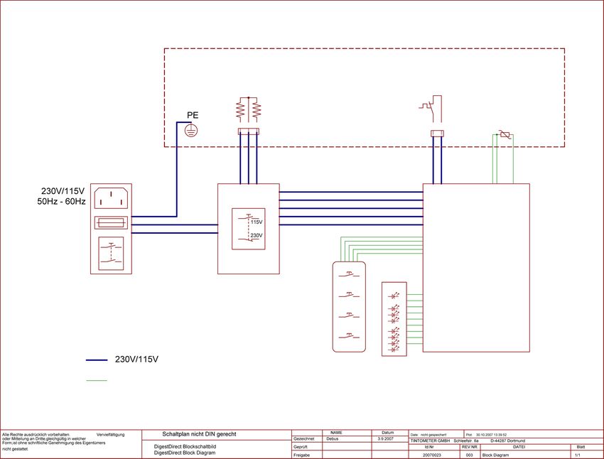
1.2   Wichtige Hinweise
      Hinweise zum Aufstellungsort
      Der Aufstellungsort darf weder extrem heiß oder kalt, noch feucht oder staubig sein.
      Hitze und Kälte können die Funktionsfähigkeit des Thermoreaktors beeinträchtigen.
      Feuchtigkeit und Staub können zu einem Ausfall des Thermoreaktors führen.
      Stellen Sie den Thermoreaktor nicht in unmittelbarer Nähe von Wärmequellen wie
      Heizkörpern oder Radiatoren auf. Das Gerät darf zudem keinen mechanischen Vibra-
      tionen oder Stößen ausgesetzt werden.
      Die an der Unter- und Rückseite des Gerätes angebrachten Lüftungsschlitze dürfen
      nicht abgedeckt sein.

      Hinweise zum Netzanschluss
      Verwenden Sie ausschließlich das für Ihr Land geeignete Netzkabel.
      Die Netzsteckdose sollte sich in direkter Nähe befinden und leicht zugänglich sein.

i     Der Thermoreaktor kann nur durch Ziehen des Netzsteckers aus der Steckdose ganz
      vom Netz getrennt werden.

      Sicherheitshinweise zum Betrieb
      Das Netzkabel darf nicht beschädigt werden. Stellen Sie keine Gegenstände auf das
      Netzkabel, und sorgen Sie dafür, dass keine Knoten am Kabel auftreten. Um das
      Kabel zu lösen, ziehen Sie stets am Stecker und nie am Kabel selbst. Ein beschädigtes
      Netzkabel kann zu Brand oder Stromschlägen führen.
      Achten Sie darauf, dass die Lüftungsschlitze nicht verdeckt werden. Die Luftzirkula-
      tion im Thermoreaktor ist erforderlich, um eine Überhitzung zu vermeiden. Wird sie
      beeinträchtigt können Brand oder ein Ausfall des Thermoreaktors die Folge sein.
      Öffnen Sie den Thermoreaktor niemals eigenständig. Andernfalls besteht die Gefahr
      eines Stromschlags oder anderer Personenschäden. Der Thermoreaktor darf nur von
      Fachpersonal geöffnet und gewartet werden.

      Sicherheitsvorschriften
      Der Heizblock kann bei entsprechender Programmierung eine Temperatur von
      150 °C erreichen und zwar sowohl während der Heizphase (wenn die HEAT-LED
      leuchtet) als auch während der Abkühlphase.
      Während dieser Zeit kann die Unterseite des Gerätes heiß sein!
      Nicht berühren, Verbrennungsgefahr!
      Die bei den Arbeiten verwendeten Materialien müssen bei den Temperaturen, die
      vom Gerät erreicht werden, beständig sein.
      Bitte unbedingt Klarsichtdeckel schließen, wenn Küvettentests im Gerät erhitzt werden.

      Reinigung
      Vor Beginn der Reinigungsarbeiten immer den Netzstecker ziehen. Die Heizplatte
      muss bei Reinigungsarbeiten kalt sein. Die Reinigung erfolgt mit einem feuchten Tuch
      und nicht brennbaren, nicht korrosiven Reinigungsmitteln.

      Schutzvorrichtungen
      Die Schutzvorrichtungen müssen gegen die vom Gerät erreichten Temperaturen und
      die beim Arbeiten benutzten Materialien und Reagenzien beständig sein.

  RD 125_7b 01/2020                                                                            5
1.3 Auspacken
Heben Sie den Thermoreaktor vorsichtig aus der Verpackung und überprüfen Sie das
Zubehör auf Vollständigkeit.
Bewahren Sie den Originalkarton und das Verpackungsmaterial für den Fall auf, dass
Sie den Reaktor einschicken oder anderweitig transportieren müssen.
Stückliste
Teil Anzahl
1 Thermoreaktor RD 125 1
2 Netzkabel (Europa-Version) 1
3 Bedienungsanleitung 1
1.4 Anschließen
Auf der Rückseite des Thermoreaktors befindet sich:
• Schiebeschalter für Netzspannung
• Stecker für Netzkabel
• Gerätesicherung 4 AT
• Netzschalter (0/I)
Das Gerät ist mit einem Wahlschalter für 115 V / 230 V ausgerüstet. Dieser
befindet sich an der Geräterückseite. Erst wenn die vorhandene Netzspannung am
Schiebeschalter richtig eingestellt ist und der Netzschalter in der Position „0“ ist,
darf das Gerät über das mit Schutzleiter versehene Kabel an das Netz angeschlossen
werden.
Schutzhaube
Schiebeschalter
Gerätesicherung für Netzspannung
Stecker für Netzkabel Netzschalter
6 RD 125_7b 01/20201.5 Bedienelemente
Start-Taste / Timer
Aufheiz-Taste Heat LED
Temperatur-Wahl-Taste Temperatur LEDs
Zeit (Intervall)-Wahl-Taste Zeit LEDs
R 125
1.6 Funktion der Bedienelemente
Start-Taste / Timer: Mit der “START“-Taste wird (nachdem die Solltemperatur
erreicht ist) die Zeitmessung (Countdown) für das eingestellte Zeitintervall aktiviert.
Der Ablauf des Zeitintervalls wird akustisch angekündigt (Beeper, siehe Seite 8) und
die Heizung automatisch abgeschaltet.
Aufheiz-Taste: Mit der „HEAT“-Taste wird (nachdem das Gerät mit dem
Hauptschalter I/O eingeschaltet wurde) der Aufheizvorgang für die eingestellte
Solltemperatur aktiviert.
Temperaturwahl-Taste: Durch mehrfaches Drücken der Taste „TEMP“ wird zwischen
100/120/150 °C Solltemperatur gewählt (Scrollen).
Zeitwahl-Taste: Durch mehrfaches Drücken der Taste „TIME“ wird zwischen den
Zeitintervallen 30/60/120/∞ (min) gewählt (Scrollen).
RD 125_7b 01/2020 72. Bedienung
In diesem Kapitel wird die Bedienung Schritt für Schritt für eine Standardanwendung
beschrieben. Von der Standardanwendung abweichende Vorgehensweisen werden in
der Tabelle „Bedienkonzept“ (siehe Seite 9) beschrieben.
Das Gerät wird mit dem Netzschalter an der Rückseite eingeschaltet (Position I). Nach
dem Einschalten zeigt das Gerät automatisch die zuletzt eingestellte Temperatur und
die zuletzt gewählte Zeitspanne an. Die entsprechenden LEDs auf der Frontplatte
leuchten. Nach dem Einschalten des Netzschalters heizt das Gerät noch nicht auf,
dazu muss die „HEAT“-Taste gedrückt werden. Nach dem Drücken der „HEAT“-Taste
leuchtet die Heat-LED.
Vor und nach dem Drücken der „HEAT“-Taste können Temperatur- u. Zeiteinstel-
lungen verändert werden. Während der Aufheizphase blinkt die Temperatur-LED,
die Zeit-LED leuchtet dauernd.
Wenn die eingestellte Solltemperatur erreicht ist, wechselt die blinkende Temperatur-
LED auf Dauerleuchten.
Der Timer beginnt mit der Zeitmessung entsprechend dem eingestellten Wert nach
Drücken der Taste „START“. Sobald die Zeitmessung beginnt, wechselt die Zeit-LED
von Dauerleuchten auf Blinken. Wenn die eingestellte Zeitspanne abgelaufen ist,
leuchten die Zeit-LED und die Temperatur-LED, während die Heat-LED aus ist (Hei-
zung ist abgeschaltet).
3. Beeper
Temperatur oder Zeit weiterschalten: kurzer Doppel-Beep
(zwei Frequenzen)
Heizung (per Heat-Taste) einschalten: langer Beep (eine Frequenz)
Heizung (per Heat-Taste) vorzeitig abschalten: langer Beep (eine Frequenz)
Temperatur-Sollwert ist erreicht: achtfacher kurzer Beep
(zwei Frequenzen)
Starten des Timers (per Start-Taste): langer Beep (eine Frequenz)
Timer ist abgelaufen: sechzehnfacher kurzer Beep
(zwei Frequenzen)
Zur Zeit ungültige Taste gedrückt kurzer einfacher Beep
(z.B. Start-Taste wenn Aufheizen (eine Frequenz)
noch nicht beendet):
Fataler Fehler,
Gerät hat sich automatisch abgeschaltet: LEDs zeigen Fehlercode
(siehe Seite 12)
anhaltender Dauer-Beep
(zwei Frequenzen), bis Gerät über
Netzschalter ausgeschaltet wird.
8 RD 125_7b 01/2020Nach Einschalten mit dem Netzschalter an der Geräterückseite heizt das Gerät nicht; dazu muss die Taste HEAT gedrückt werden.(Zustand 1)
Nach der Aufheizphase startet die voreingestellte Zeitmessung erst nach Drücken der START Taste.(Zustand 3)
4.
Temp-/Time- Nächster
Zustand Heat-LED Temp.-LED Time-LED Heat-Taste Start-Taste Heizung
Taste Zustand
An (zuletzt An (zuletzt Wenn HEAT
1. Wartet auf HEAT Drücken: => Einstellen
Aus gewählter gewählte Ignorieren Aus Taste gedrückt:
Taste Zustand 2 möglich
Sollwert) Zeit) Zustand 2
Aufheizen Wenn
RD 125_7b 01/2020
Drücken => Einstellen oder Solltemperatur
2. Aufheizen An Blinkt Dauernd an Ignorieren
Zustand 1 möglich abkühlen erreicht:
lassen Zustand 3
Bedienkonzept
Wenn nicht Wenn Start
t=∞: Start gedrückt:
möglich Zustand 4
(t≠∞)
Nach
3. Wartet auf Drücken => Einstellen Temperatur Ändern von
An Dauernd an Dauernd an Solltemperatur:
START Taste Zustand 1 möglich halten
Zustand 2
Wenn t=∞:
ignorieren Wenn zu
sehr von
Solltemperatur
entfernt:
Zustand 2
Wenn Zeit
Drücken => Temperatur
4. Zeit läuft An Dauernd an Blinkt Ignorieren Ignorieren abgelaufen:
Zustand 1 halten
Zustand 1
Heat-LED an bedeutet: aufheizen oder Temperatur halten (wenn Temperatur über Sollwert, abkühlen lassen)
aus bedeutet: nicht heizen
Temp.-LED
blinkt bedeutet: Sollwert ist nicht erreicht, Aufheizen (bzw. Abkühlen) läuft
an bedeutet: in Verbindung mit der Heat-LED an: Sollwert ist erreicht und wird gehalten
in Verbindung mit der Heat-LED aus: zeigt nur Sollwert an, Istwert kann anders sein
9
Zeit-LED blinkt bedeutet: Timer läuft
an bedeutet: Timer läuft noch nicht oder nicht mehr5. Wartung
Der Reaktor ist mit einer 4-A-trägen Sicherung abgesichert. Diese befindet sich auf
der Rückseite unterhalb des Netzschalters.
Sollte die Sicherung gewechselt werden müssen, wird der Reaktor zuerst vom Netz
getrennt (Ziehen des Netzsteckers aus der Netzsteckdose) und dann der Sicherungs-
halter mit einem geeigneten Werkzeug aus der Arretierung gelöst.
6. Reinigung
Der Reaktor wird vom Netz getrennt (Ziehen des Netzsteckers aus der Netzsteckdose).
Reinigungsarbeiten erst vornehmen, wenn der Thermoreaktor vollständig abgekühlt
ist. Zur Reinigung eignet sich ein feuchtes Tuch mit nicht brennbaren, nicht aggres-
siven schleif- und scheuermittelfreien Detergenzien.
ACHTUNG:
Für den Fall, dass in dem Heizblock eine oder mehrere Küvetten platzen und/oder
Inhalte der Küvetten unbeabsichtigt ausgetreten sind, muss die sichere Entsorgung
des Küvettenglases und -inhalts gemäß den Angaben im entsprechenden Sicherheits-
datenblatt erfolgen.
Ein kontaminierter Reaktor darf nicht weiterverwendet werden und muss für den
Austausch des Aluminiumblocks zum Hersteller oder einem autorisierten
Servicecenter geschickt werden.
7. Technische Daten
Netzanschluss V/Hz 230 / 50-60 oder
115 / 50-60 (über Wahlschalter)
Leistungsaufnahme W 550
Abmessungen mm 248 x 219 x 171
Gewicht kg 3,9
Werkstoffe Gehäuse Ober-/Unterteil: ABS
Innengehäuse: PBT
Schutzgitter: PPS
Klarsichtdeckel: PC
Heizblock: Aluminium
Küvettenaufnahme 24 Bohrungen,
Aluminiumblock Durchmesser 16,2 mm ± 0,2 mm
Temperaturwahl °C 100 / 120 /150
Temp.-Überwachung Pt100 A-Klasse
Temperaturstabilität °C ±1
am Pt100
Zeitintervalle min 30 / 60 / 120 / und unbegrenzt (∞)
Aufheizgeschwindigkeit
(20 °C --> 150 °C) min 12
Steuerung Mikroprozessor
Überhitzungsschutz °C am Thermoblock bei 190
Beeper (Piezo Summer) dB max. 88
Umgebungsbed. Temp. °C 10 – 40
relative Feuchte % max. 85
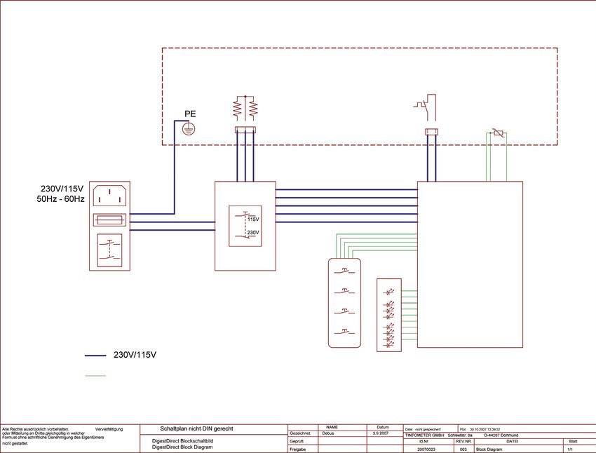
10 RD 125_7b 01/20208. Elektrisches Blockschaltbild
RD 125_7b 01/2020 1112
9.
Piepton
Fehler-Nr Fehler mögliche Ursachen Temp-LEDs LED 30 min. LED 60 min. LED 120 min. LED ∞
Daueralarm
Netzfrequenz unter 50Hz
1 Netzfrequenz oder über 60Hz; ein aus aus aus ein ja
Fehler auf Platine
Ansprechen der
2 Fehler auf Platine ein aus aus ein aus ja
Schutzschaltung
3 ADC-Fehler Fehler auf Platine ein aus aus ein ein ja
Zuleitung zum Pt100
4 Kabelbruch unterbrochen; sehr abrupte ein aus ein aus aus ja
Temperaturänderung
LED-Fehlercode
Pt100 nicht richtig auf
Alublock befestigt;
5 Timeout beim Aufheizen Kurzschluss des Pt100; ein aus ein aus ein ja
verringerte oder gar keine
Heizleistung
unterer Referenzwert
6 Fehler auf Platine ein aus ein ein aus ja
außerhalb Toleranz
oberer Referenzwert
7 Fehler auf Platine ein aus ein ein ein ja
außerhalb Toleranz
Zuleitung zum Pt100
Temperaturmessung
8 unterbrochen ein ein aus aus aus ja
am oberen Anschlag
Fehler auf Platine
100° ein
EMV-relevante Störung von
9 Programmabsturz 120° aus ein aus ein aus nein
außen (HF, Funken etc)
150° ein
Übertemperatur auf
10 Gerät überhitzt ein ein ein aus aus ja
Platine
RD 125_7b 01/2020RD 125_7b 01/2020 13
Content
     1.        RD 125  . . . . . . . . . . . . . . . . . . . . . . . . . . . . . . . . . . . . . . . . . . . . . . . . .     15
     1.1       Introduction . . . . . . . . . . . . . . . . . . . . . . . . . . . . . . . . . . . . . . . . . . . . . .      15
     1.1.1     Preface . . . . . . . . . . . . . . . . . . . . . . . . . . . . . . . . . . . . . . . . . . . . . . . . . .   15
     1.1.2     Guide to symbols . . . . . . . . . . . . . . . . . . . . . . . . . . . . . . . . . . . . . . . . . .          15
     1.2       Important information . . . . . . . . . . . . . . . . . . . . . . . . . . . . . . . . . . . . . .             16
     1.3       Unpacking . . . . . . . . . . . . . . . . . . . . . . . . . . . . . . . . . . . . . . . . . . . . . . .       17
     1.4       Connecting  . . . . . . . . . . . . . . . . . . . . . . . . . . . . . . . . . . . . . . . . . . . . . .       17
     1.5       Buttons  . . . . . . . . . . . . . . . . . . . . . . . . . . . . . . . . . . . . . . . . . . . . . . . . .    18
     1.6       Function of buttons . . . . . . . . . . . . . . . . . . . . . . . . . . . . . . . . . . . . . . . .           18
     2.        Work session  . . . . . . . . . . . . . . . . . . . . . . . . . . . . . . . . . . . . . . . . . . . 19
     3.        Beeper  . . . . . . . . . . . . . . . . . . . . . . . . . . . . . . . . . . . . . . . . . . . . . . . . . 19
     4.        Function schematics  . . . . . . . . . . . . . . . . . . . . . . . . . . . . . . . . . . . . . . 20
     5.        Maintenance  . . . . . . . . . . . . . . . . . . . . . . . . . . . . . . . . . . . . . . . . . . . . 21
     6.        Cleaning  . . . . . . . . . . . . . . . . . . . . . . . . . . . . . . . . . . . . . . . . . . . . . . . 21
     7.        Technical data  . . . . . . . . . . . . . . . . . . . . . . . . . . . . . . . . . . . . . . . . . . . 21
     8.        Wiring diagramm  . . . . . . . . . . . . . . . . . . . . . . . . . . . . . . . . . . . . . . . . 22
     9.        Error code (LED indication)  . . . . . . . . . . . . . . . . . . . . . . . . . . . . . . . . 23

                                                     Important Information
                  To Preserve, Protect and Improve the Quality of the Environment
                          Disposal of Electrical Equipment in the European Union
          Because of the European Directive 2012/19/EU your electrical instrument must not be
                                  disposed of with normal household waste!
          Tintometer GmbH will dispose of your electrical instrument in a professional and envi-
                  ronmentally responsible manner. This service, excluding the cost of trans-
                  portation is free of charge. This service only applies to electrical instruments
                purchased after 13th August 2005. Send your electrical Tintometer instruments
                                   for disposal freight prepaid to your supplier.

14                                                                                                       RD 125_7b 01/2020
1. RD 125
1.1 Introduction
Please read the manual before using the unit in particular taking note of the warning
symbols listed below.
The manufacture does not take responsibility for any issues caused by use of the unit
not in accordance with the instructions laid out in this manual.
1.1.1 Preface
The reactor is only suitable for 16 mm Ø test tubes, closed with a lid.
The unit has a transparent cover, which has to be closed during the heating process.
The required temperatures and the corresponding time periods are specific for the
different test tube types and specified in the corresponding method descriptions.
Don’t exceed temperatures or time spans in any case.
All warning labels must NOT be removed and should be replaced if they become
damaged or faded.
1.1.2 Guide to symbols
The symbols below are used in this manual to indicate where there is risk of injury or
damaging devices or to indicate especially useful information:
DANGER!
Indicates risk of injury.
When not following instructions, severe injury or death may result.
ATTENTION!
Indicates possible damage to devices.
When not following instructions, devices may be heavily damaged.
i IMPORTANT!
Indicates hints on operation and other useful information.
ATTENTION!
Hot surfaces! Do not touch, risk to be badly burned!
Read all instructions before using the instrument.
RD 125_7b 01/2020 151.2 Important information
Note on reactor placement
The setup location must not be extremely hot, cold, humid or dusty. Heat and cold
can impair the functionality of the reactor. Humidity and dust can cause the reactor
to fail.
Do not place the reactor near heaters such as radiators or the like. Do not expose the
reactor to mechanical vibrations or jarring.
Do not block or cover the ventilation openings.
Notes on power connection
Only use the power cord designated for use in your country.
i
The wall outlet should be within easy reach.
Pulling the power plug is the only way to disconnect the reactor from the power
source
Safety instructions for operation
The power cord must not be damaged. Do not place any objects on the power cord
and make sure it does not have any knots. To unplug the cord, always pull on the
plug and not on the cable itself.
Avoid covering the ventilation slots. Air circulation is necessary to prevent the reactor
from overheating. If the air circulation is restricted it could cause fire or damage the
reactor.
Never open the reactor housing yourself. There is a danger of electric shock
and other hazards. The reactor may only be opened and serviced by qualified
professionals.
Safety rules
The heating block if programmed, may reach a temperature of 150 °C, this hap-
pens during the heating phase when the red LED is lighted. Please note the unit will
remain hot during the cooling phase even though the LED-light may be off.
During this phase the base of the instrument may be very hot!
Do not touch, risk to be badly burned!
The materials used during the work must be compatible with the temperatures
reached by the unit.
Cleaning
The heating plate must be allowed to cool before cleaning.
Use a damp cloth with a non flammable, non corrosive detergent .
Personal Protection Equipment
The equipment used for personal protection must be compatible with the reached
temperature and the dangers due to the working materials.
16 RD 125_7b 01/20201.3 Unpacking
Carefully inspect all items to ensure that every part on the list below is present
and no visible damage has occurred during transportation.
Store the packing material to return the unit for repair or other kinds of transport.
The table below shows the parts included in the packing.
Part list
Part Quantity
1 Thermoreactor RD 125 1
2 Power cord (European version) 1
3 Instruction manual 1
1.4 Connecting
On the reverse side of the reactor:
• Selector for voltage 115 V / 230 V
• Plug for power cord
• Fuse 4 AT
• ON/OFF Switch (0/I)
Before connecting to power supply check that the ON/OFF switch is turned to “0”
and check that the voltage selector (115 V/230 V) corresponds to the voltage
supplied by the electric socket.
Cover
Selector
Fuse for voltage
Plug for power cord ON/OFF Switch
RD 125_7b 01/2020 171.5 Buttons
Start key / Timer
Heat key Heat LED
Temperature key Temperature LEDs
Time (interval) key Time LEDs
R 125
1.6 Function of buttons
Start key (for timer): By pressing this key the work cycle will start with the
pre-selected values for temperature and time. At the end of the work cycle the
beeper will sound (Beeper, see page 19) and the heater automatically switches off.
Heat key: By pressing this key (after switching the instrument on using the main on/
off switch) the reactor will heat up to the pre-selected temperature.
Temp key: By pressing this key the temperature is selected (scrolling). It is possible
to select between 100/120 and 150 °C. When a temperature is selected the
corresponding LED will light.
Time key: By pressing this key the time is selected (scrolling). It is possible to select
between: 30/60/120 min or ∞ (infinite). When a time is selected the corresponding
LED will light.
18 RD 125_7b 01/20202. Work session
This section describes the use of the reactor for a standard application.
For further applications please refer to “Function schematics” (see page 20).
After the unit is switched on (main switch, reverse side, position I) the keypad
automatically shows the last selected temperature and time span.
The corresponding LEDs are lighted.
After switching on the block heating does not commence automatically.
For heating up the unit press the “Heat” key.
After pressing this key the Heat LED is lighted.
Before and after pressing the “Heat” key temperature and time span still can be
changed.
During heating up the Temperature LED will light intermediately, when the selected
temperature is reached the Temperature LED is lighted permanently.
By pressing the “Start” key the timer starts the work cycles corresponding to the cho-
sen time span (indication by Time LED). Starting the work cycle the Time LED changes
from lighted to flashing.
When the work cycle ends Time LED and Temperature LED are lighted while the Heat
LED is off.
At the end of the work cycle the heater is switched off.
3. Beeper
Select temperature or time: short double beep
(two frequencies)
Switch heater on: long beep (one frequency)
Switch heater off: long beep (one frequency)
Temperature reaches the selected value: 8 x short beep
(two frequencies)
Start of countdown: long beep (one frequency)
End of countdown: 16 x short beep
(two frequencies)
Pressing a key which is inactive short beep
(at the moment): (one frequency)
Malfunction: Continuous beep (2 frequencies)
until the instruments is switched
off with the main switch
(position “O”). In this case the LED
combination according pages 23
allows a failure definition.
RD 125_7b 01/2020 1920
After switching on the instrument with the main on/off switch, the heater is not active. Press the HEAT-key for heating up (status 1).
4.
After heating up to the selected temperature the timer starts after pressing START-key (status 3).
Temp-/Time- next possible
Status Heat-LED Temp.-LED Time-LED Heat-key Start-key Heater
key status
After pressing
1. Waiting for last selected last selected Press: => Selection
Off Ignore Off HEAT-key:
pressing HEAT-key temperature time-span Status 2 possible
Status 2
If selected
Heating up
Press => Selection temperature is
2. Heating up On Flashing On Ignore or Cooling
Status 1 possible reached:
down
Status 3
After pressing
Press for t =
Start-key:
30, 60, 120
Status 4
Function schematics
(t≠∞)
Temperature-
If selected
controlled for
3. Waiting for Press => Selection temperature will
On On On stability of
pressing START-key Status 1 possible be changed:
the selected
Ignore for Status 2
temperature
t=∞ If temperature
to different to
selected one:
Status 2
End of count
4. Time: Count Press => Stable
On On Flashing Ignore Ignore down:
down Status 1 Temperature
Status 1
Heat-LED On: Heating up or stabilizing selected temperature.
Off: Heater is off
Temp.-LED Flashing: Selected temperature is not reached (heating up or cooling down)
Together with HEAT-LED On: Selected temperature is reached
RD 125_7b 01/2020
Together with HEAT-LED Off: Indicates selected temperature without indication of the real temperature of the reactor
Time-LED Flashing: Count down function
On: indication of selected time-span without count down function.5. Maintenance
The unit is protected by a 4AT fuse. The position of the fuse holder is on the reverse
side of the unit under the main switch.
Should the fuse need changing, disconnect the unit from the power supply and open
the cover with a suitable tool to access the fuse.
6. Cleaning
No special maintenance is necessary apart from periodic cleaning of the unit.
Disconnect the unit from power supply and use a dust-free cloth with a non flamma-
ble, non aggressive detergent to clean the unit.
ATTENTION:
If the reactor is contaminated by spillage of the tube contents or breakage of the test
tube, the disposal of waste (both glass and liquid) must be done according to the
instructions set out in the Material Safety Data Sheet (MSDS).
A contaminated aluminium block must be replaced prior to further use of the reactor.
The reactor should be sent to the manufacturer or an authorised service centre.
7. Technical data
Power supply V/Hz 230 / 50-60 or
115 / 50-60 selectable
Power W 550
Size mm 248 x 219 x 171
Weight kg 3.9
Construction materials Housing: ABS
Protection grid: PPS
Lid: PC
Block insert: PBT
Heating block: Aluminium
Holes in the
aluminium block 24 holes, ø 16.2 mm ± 0.2 mm
Selectable temperatures °C 100 / 120 /150
Probe type Pt100 A class
Temperature stability °C ±1
at the Pt100
Selected time min 30 / 60 / 120 / continuous (∞)
Heating up from
(20 °C --> 150 °C) min 12
Thermoregulation Microprocessor
Protection °C at the Alublock for 190
against overheating
Beeper dB max. 88
Environmental conditions (operation)
Temperature °C 10 – 40
Humidity % max. 85
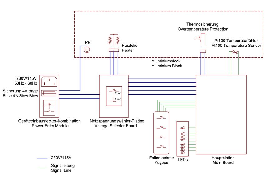
RD 125_7b 01/2020 218. Wiring diagramm 22 RD 125_7b 01/2020
No.   Error type                Possible reason(s)        Temp LED   LED 30 min   LED 60 min   LED 120 min   LED ∞   Continuous beep   9.
                                                    Frequency higher/lower
                    1     Power supply frequency    50Hz / 60Hz;              on         off          off          off           on      yes
                                                    Mainboard faulty
                    2     Safety feature reaction   Mainboard faulty          on         off          off          on            off     yes
                    3     ADC error                 Mainboard faulty          on         off          off          on            on      yes
                                                    internal connection
                    4     Wiring problem                                      on         off          on           off           off     yes

RD 125_7b 01/2020
                                                    incomplete
                                                    - no power;
                    5     Heating problem           - reactor power           on         off          on           off           on      yes
                                                    - probe problem
                    6     T value underrange        Mainboard faulty          on         off          on           on            off     yes
                    7     T value overrange         Mainboard faulty          on         off          on           on            on      yes
                                                    Probe connection faulty
                    8     Temperature too high                                on         on           off          off           off     yes
                                                    Mainboard faulty
                                                                              100° on
                                                                                                                                                           Error Code (LED indication)

                    9     Microprocessor failure    EMC-interference          120° off   on           off          on            off     no
                                                                              150° on
                          Temperature on
                    10                              Unit overheated           on         on           on           off           off     yes
                          mainboard too high

23
Table des matières
1. RD 125 . . . . . . . . . . . . . . . . . . . . . . . . . . . . . . . . . . . . . . . . . . . . . . . . . 25
1.1 Introduction . . . . . . . . . . . . . . . . . . . . . . . . . . . . . . . . . . . . . . . . . . . . . . 25
1.1.1 Usage conforme à la détermination de l’appareil . . . . . . . . . . . . . . . . . . 25
1.1.2 Utilisation des symboles . . . . . . . . . . . . . . . . . . . . . . . . . . . . . . . . . . . . . 25
1.2 Indications importantes . . . . . . . . . . . . . . . . . . . . . . . . . . . . . . . . . . . . . 26
1.3 Déballage . . . . . . . . . . . . . . . . . . . . . . . . . . . . . . . . . . . . . . . . . . . . . . . . 27
1.4 Connexion . . . . . . . . . . . . . . . . . . . . . . . . . . . . . . . . . . . . . . . . . . . . . . . 27
1.5 Eléments de manipulation . . . . . . . . . . . . . . . . . . . . . . . . . . . . . . . . . . . 28
1.6 Fonction des éléments de manipulation . . . . . . . . . . . . . . . . . . . . . . . . . 28
2. Manipulation . . . . . . . . . . . . . . . . . . . . . . . . . . . . . . . . . . . . . . . . . . . 29
3. Beeper . . . . . . . . . . . . . . . . . . . . . . . . . . . . . . . . . . . . . . . . . . . . . . . . . 29
4. Concept de manipulation . . . . . . . . . . . . . . . . . . . . . . . . . . . . . . . . . 30
5. Maintenance . . . . . . . . . . . . . . . . . . . . . . . . . . . . . . . . . . . . . . . . . . . . 31
6. Nettoyage . . . . . . . . . . . . . . . . . . . . . . . . . . . . . . . . . . . . . . . . . . . . . . 31
7. Données techniques . . . . . . . . . . . . . . . . . . . . . . . . . . . . . . . . . . . . . . 31
8. Diagramme de connexion . . . . . . . . . . . . . . . . . . . . . . . . . . . . . . . . . 32
9. Code d’erreur DEL . . . . . . . . . . . . . . . . . . . . . . . . . . . . . . . . . . . . . . . 33
Notice importante
Conserver, protéger et optimiser la qualité de l’environnement
Élimination du matériel électrique dans l’Union Européenne
Conformément à la directive européenne nº 2012/19/UE, vous ne devez plus jeter vos
instruments électriques dans les ordures ménagères ordinaires !
La société Tintometer GmbH se charge d’éliminer vos instruments électriques de façon
professionnelle et dans le respect de l’environnement. Ce service, qui ne
comprend pas les frais de transport, est gratuit. Ce service n’est valable que
pour des instruments électriques achetés après le 13 août 2005. Nous vous
prions d’envoyer vos instruments électriques Tintometer usés à vos frais à votre
fournisseur.
24 RD 125_7b 01/20201. RD 125
1.1 Introduction
Lire le mode d’emploi avant de mettre l’appareil en service. Le fabricant décline toute
responsabilité en cas d’utilisation non adéquate de l’appareil et le non respect des
instructions d’utilisation.
1.1.1 Usage conforme à la détermination de l’appareil
Ce thermoréacteur est uniquement destiné au chauffage de tubes fermés de diamè-
tre 16 mm.
Il est impératif de tenir le couvercle de protection fermé lors du démarrage du proces-
sus et de la période de chauffage.
La température à sélectionner et l’intervalle de temps dépendent du test en cuvette
et sont indiqués dans les instructions d’analyse propres à ceux-ci. Il est impératif de
bien respecter ces informations.
Les étiquettes fixées sur l’appareil attirent l’attention sur les dangers auxquels
l’utilisateur s’expose lors de l’utilisation ou la maintenance. Ne pas enlever ces
étiquettes et les remplacer si elles sont devenues illisibles.
1.1.2 Utilisation des symboles
Dans ce mode d’emploi, les symboles suivants ont été utilisés afin d’attirer l’attention
sur un danger potentiel humain ou matériel et apporter des informations utiles :
DANGER ELECTRIQUE
Définit un danger potentiel pour l’utilisateur. Le non respect peut entraîner la mort ou
des blessure très sévères.
ATTENTION !
Indique un danger matériel potentiel. Le non respect peut entraîner des dégâts
importants de l’appareil.
i IMPORTANT !
Donne des conseils d’utilisation et d’autres informations particulièrement précieuses.
ATTENTION !
Surface brûlante ! Ne pas toucher : danger de brûlure !
Lire le mode d’emploi avant de mettre l’appareil en service.
RD 125_7b 01/2020 251.2 Indications importantes
Indications concernant le lieu d’installation de l’appareil
Le lieu d’installation de l’appareil ne doit être ni extrêmement chaud, ni froid, ni
humide ou poussiéreux. La chaleur et le froid peuvent altérer les fonctions du ther-
moréacteur. L’humidité et la poussière peuvent provoquer une panne de l’appareil.
Ne pas exposer le thermoréacteur à proximité d’une source de chaleur comme les
radiateurs ou radiateurs d’appoint. L’appareil ne doit être exposé à des vibrations
mécaniques ou à des coups.
Ne pas couvrir les fentes d’aération dessous et derrière l’appareil.
Indications concernant le raccordement au secteur
Utiliser uniquement un câble adapté pour votre pays.
La prise de courant doit se trouver à proximité directe et être aisément accessible.
i Le thermoréacteur ne peut être complètement déconnecté du secteur qu’en retirant
la fiche de la prise.
Indications de sécurité pour l’utilisation
Le câble ne doit pas être endommagé. Ne pas poser d’objet sur le câble et s’assurer
que celui- ci n’est pas noué. Pour débrancher l’appareil, tirer sur la fiche mais
jamais sur le câble. Un câble endommagé peut entraîner un danger d’incendie ou
d’électrocution.
Assurez vous que les fentes d’aération ne sont pas couvertes. La circulation d’air dans
le thermoréacteur est nécessaire pour éviter une surchauffe. L’altération de l’aération
peut entraîner un incendie ou une panne de l’appareil.
N’ouvrez jamais le thermoréacteur par vous-même sous peine de vous exposer à une
décharge électrique ou des dégâts humains. L’appareil ne peut être ouvert et entrete-
nu que par un personnel qualifié.
Consignes de sécurité
Le bloc de chauffage peut atteindre une température de 150 °C par programmation
correspondante, et ce aussi bien durant la phase de chauffage (lorsque la DEL HEAT
est allumée) que durant celle de refroidissement.
Durant cette période, le dessous de l’appareil peut être brûlant.
Ne pas toucher, danger de brûlure !
Les matériaux utilisés durant les manipulations doivent être résistants aux tempéra-
tures pouvant être atteintes par l’appareil.
Il est impératif de fermer le couvercle transparent lorsque les tests en cuvettes sont en
cours de chauffage.
Nettoyage
Toujours retirer la fiche de la prise secteur avant de commencer les travaux de netto-
yage. La plaque chauffante doit être froide. Utiliser un chiffon humide et des produits
de nettoyage non inflammables et non corrosifs.
Dispositifs de protection
Les dispositifs de protection doivent être résistants aux température pouvant être
atteintes par l’appareil et aux matériaux et réactifs utilisés lors des travaux.
26 RD 125_7b 01/20201.3 Déballage
Retirer avec précaution le thermoréacteur de l’emballage et vérifier l’intégralité du
contenu de livraison.
Gardez le carton original et les matériaux d’emballage au cas où vous devriez
retourner l’appareil ou le transporter.
Nomenclature
Pièce Nombre
1 Thermoréacteur RD 125 1
2 Câble de raccordement (version européenne) 1
3 Mode d’emploi 1
1.4 Connexion
A l’arrière du thermoréacteur se trouvent :
• interrupteur coulissant pour règlage de la tension
• fiche pour câble secteur
• Fusible 4 AT
• Interrupteur réseau (0/I)
L’appareil est équipé d’un interrupteur sélecteur pour 115 V / 230 V. Celui-ci se
trouve à l’arrière de l’appareil. L’appareil ne peut être connecté au secteur par le
câble de sécurité qu’après que la tension ait été réglée par l’interrupteur coulissant et
l’interrupteur réseau soit en position « 0 ».
Couvercle de protection
Interrupteur coulissant
Fusible pour la tension
Prise pour câble secteur Interrupteur réseau
RD 125_7b 01/2020 271.5 Eléments de manipulation
Touche de mise en marche/timer
Touche chauffage DEL chaleur
Touche de sélection de la température DEL température
Touche temps (intervalle) DEL temps
R 125
1.6 Fonction des éléments de manipulation
Touche de mise en marche/timer : en appuyant sur START, le compte à rebours est
activé pour l’intervalle de temps réglé (après que la température à atteindre soit
atteinte).
L’expiration de l’intervalle de temps est signalée par un signal acoustique (beeper,
voir page 29) et le chauffage s’arrête automatiquement.
Touche chauffage : en appuyant sur la touche HEAT, le processus de chauffage pour
la température sélectionnée est activé (après que l’appareil ait été mis en marche à
l’aide de la touche I/0)
Touche de sélection de la température : en appuyant à plusieurs reprises sur la touche
TEMP, vous pouvez sélectionner entre 100/120/150 °C (faire défiler).
Touche temps (intervalle) : en appuyant à plusieurs reprises sur la touche TIME, vous
pouvez sélectionner entre 30/60/120/ ∞ (min) (faire défiler).
28 RD 125_7b 01/20202. Manipulation
Ce chapitre décrit l’utilisation pas à pas pour une application standard. La marche
à suivre pour une application autre que l’application standard est décrite dans le
tableau « concept de manipulation » (voir page 30).
L’appareil est mis en marche à l’aide de l’interrupteur à l’arrière de l’appareil (position I).
Après la mise en marche, l’appareil affiche automatiquement la dernière température
et la dernière tension sélectionnées. Les DEL correspondant s’allument à l’avant de
l’appareil. L’appareil ne chauffe pas directement après la mise en marche, pour cela il
faut appuyer sur la touche HEAT. Après avoir appuyé sur la touche HEAT, la DEL HEAT
s’allume.
Avant comme après avoir appuyé sur la touche HEAT, la température et le réglage du
temps peuvent être modifiés. Pendant la période de chauffage, la DEL TEMP clignote
et la DEL TIME s’allume en continu.
La température sélectionnée étant atteinte, la DEL TEMP ayant clignoté jusque là
s’allume en continu.
Le compte à rebours commence en appuyant sur la touche START. Aussitôt que
le compte à rebours commence, la DEL TIME passe de l’allumage en continu au
clignotement. La période de chauffage sélectionnée passée, les LED TIME et TEMP
s’allument, tandis que le DEL HEAT s’éteint (le chauffage est désactivé).
3. Beeper
Sélection de la température ou du temps : double beep court
Mettre le chauffage en marche (par touche HEAT) : beep long (une fréquence)
Arrêt anticipé du chauffage : beep long (une fréquence)
Température à atteindre est atteinte : 8 beeps courts (2 fréquences)
Mise en marche du timer (par touche start) : beep long (une fréquence)
Compte à rebours écoulé : 16 beeps courts (2 fréquences)
Touche non valide appuyée (ex : beep court (une frèquence)
Touche start lorsque le chauffage
n’est pas terminé :
Erreur fatale, les DEL affichent message
l’appareil s’est éteint utomatiquement d’erreur (voir pages 33)
beep continu (2 fréquences)
jusqu’à la mise hors service.
RD 125_7b 01/2020 2930
Après la mise en marche à l’aide de l’interrupteur réseau à l’arrière de l’appareil, celui-ci ne chauffe pas. Pour cela, appuyer sur la touche HEAT (état 1).
4.
Après la phase de chauffage, le compte à rebours se met en marche seulement après avoir appuyé sur la touche START (état 3).
Touche Touche
Etat DEL-HEAT DEL Temp. DEL Time Touche HEAT Chauffage Etat suivant
START Temp-/Time
Allumé
Allumé
(valeur à
1. Attend la touche (temps Appuyer: => Réglage Si touche HEAT
Eteint atteindre Ignorer Eteint
HEAT sélectionné Etat 2 possible appuyée : état 2
sélectionnée
en dernier)
en dernier)
Laisser Si température
Appuyer => Réglage
2. Chauffage Allumé Clignote En continu Ignorer chauffer ou à atteindre est
Etat 1 possible
refroidir atteinte : état 3
Si t n’est
pas = ∞: Si Start appuyé :
démarrage Etat 4
possible (t≠∞)
Concept de manipulation
Après
3. Attend la touche Appuyer => Réglage Tenir la changement de
Allumé En continu En continu la température
START état 1 possible température
à atteindre :
Si t = ∞: Etat 2
Ignorer
Si trop éloigné
de température
à atteindre :
Etat 2
Appuyer => Tenir la Quand temps
4. Temps s’écoule Allumé En continu Clignote Ignorer Ignorer
Etat 1 température écoulé : état 1
DEL HEAT : allumé signifie : chauffer ou tenir température (si température supérieure à température à atteindre : laisser refroidir)
Eteint signifie : ne pas chauffer
RD 125_7b 01/2020
DEL temp. :
Clignotement signifie : valeur à atteindre pas atteinte, chauffage (ou refroidissement) en cours
Allumé signifie : en combinaison avec la DEL HEAT allumée : valeur atteinte et tenue
En combinaison avec la DEL HEAT éteinte : affiche seulement la valeur à atteindre, la valeur nominale peut être autre.
DEL time : clignotement signifie : compte à rebours en cours
Allumé signifie : compte à rebours n’est pas encore ou plus en cours.5. Maintenance
Le réacteur est équipé d’un fusible 4-A. Celui-ci se trouve à l’arrière, en dessous de
l’interrupteur réseau.
Si vous deviez changer le fusible, d’abord débrancher le réacteur du secteur (retirer la
fiche de la prise) et desserrer le porte-fusible avec un outil adapté.
6. Nettoyage
Débrancher le réacteur du secteur (retirer la fiche de la prise). Commencer les travaux
de maintenance seulement après que le réacteur ait totalement refroidi.
Pour le nettoyage, utiliser un chiffon humide et des détergents non inflammables,
non agressifs et non abrasifs.
ATTENTION :
Pour le cas où une ou plusieurs cuvettes et /ou leur contenu s’est échappé, la collecte
du verre des cuvettes et de leur contenu doit s’effectuer selon les instructions indi-
quées dans la fiche de sécurité correspondante.
Un réacteur contaminé ne doit pas être utilisé et doit être retourné au fabricant ou
un centre de maintenance autorisé pour échange de la plaque chauffante.
7. Données techniques
Connexion secteur V/Hz 230 / 50-60 ou
115 / 50-60 (par interrupteur coulissant)
Puissance W 550
Dimensions mm 248 x 219 x 171
Poids kg 3,9
Matériau Boîtier supérieur/inférieur: ABS
Boîtier intérieur: PBT
Grille protectrice: PPS
Couvercle transparent: PC
Bloc chauffant: Aluminium
Nombre de cuvettes 24 emplacements,
Bloc aluminium Diamètre 16,2 mm ± 0,2 mm
Sélection de la °C 100 / 120 /150
température
Contrôle de la température Pt100 classe A
Stabilité de la température °C ±1
a Pt100
Intervalle de temps min 30 / 60 / 120 / et illimité (∞)
Rapidité de chauffage
(20 °C --> 150 °C) min 12
Pilotage microprocesseur
Protection contre °C au thermobloc à 190
surchauffe
Beeper (piezo Summer) dB max. 88
Conditions ambiantes °C 10 – 40
Humidité relative % max. 85
RD 125_7b 01/2020 3132
8.
Protection contre surchauffe
Sonde de température
Chauffage Pt100
Bloc aluminium
Fusible 4A
Diagramme de connexion
Connecteur d‘alimentation secteur Platine pour sélection de voltage
Ecran DEL Platine principale
Ligne de signal
RD 125_7b 01/2020N° erreur Erreur Causes possibles DEL temp. DEL 30 min. DEL 60 min. DEL 120 min. DEL ∞ Signal 9.
Fréquence secteur inférieure
à 50 Hz ou supérieure à
1 Fréquence secteur Allumé Eteint Eteint Eteint Allumé oui
60 Hz
Erreur sur platine
2 Réaction de la sécurité Erreur sur platine Allumé Eteint Eteint Allumé Eteint oui
3 Erreur ADC Erreur sur platine Allumé Eteint Eteint Allumé Allumé oui
RD 125_7b 01/2020
Connexion interne
4 Rupture de câble Allumé Eteint Allumé Eteint Eteint oui
incomplète
Pt100 pas bien fixé au bloc
aluminium ;
Court-circuit du Pt100 ;
5 Problème de chauffage Allumé Eteint Allumé Eteint Allumé oui
Puissance de chauffage
Code d’erreur DEL
réduite ou pas de puissance
de chauffage
Valeur inférieure de
6 Erreur sur platine Allumé Eteint Allumé Allumé Eteint oui
référence hors tolérance
Valeur supérieure de
7 Erreur sur platine Allumé Eteint Allumé Allumé Allumé oui
référence hors tolérance
Alimentation de Pt100
8 Température trop élevée interrompue Allumé Allumé Eteint Eteint Eteint oui
Erreur sur platine
100° allumé
9 Chute du programme Interférence EMV 120° éteint Allumé Eteint Allumé Eteint non
150° allumé
10 Surchauffe sur platine Appareil en surchauffe Allumé Allumé Allumé Eteint Eteint oui
33Contenido
1. RD 125 . . . . . . . . . . . . . . . . . . . . . . . . . . . . . . . . . . . . . . . . . . . . . . . . . 35
1.1 Introducción . . . . . . . . . . . . . . . . . . . . . . . . . . . . . . . . . . . . . . . . . . . . . . 35
1.1.1 Uso conforme a lo prescrito . . . . . . . . . . . . . . . . . . . . . . . . . . . . . . . . . 35
1.1.2 Utilización de los símbolos . . . . . . . . . . . . . . . . . . . . . . . . . . . . . . . . . . . 35
1.2 Indicaciones importantes . . . . . . . . . . . . . . . . . . . . . . . . . . . . . . . . . . . . 36
1.3 Desempaquetar . . . . . . . . . . . . . . . . . . . . . . . . . . . . . . . . . . . . . . . . . . . 37
1.4 Conexión . . . . . . . . . . . . . . . . . . . . . . . . . . . . . . . . . . . . . . . . . . . . . . . . 37
1.5 Elementos de mando . . . . . . . . . . . . . . . . . . . . . . . . . . . . . . . . . . . . . . . 38
1.6 Función de los elementos de mando . . . . . . . . . . . . . . . . . . . . . . . . . . . 38
2. Manejo . . . . . . . . . . . . . . . . . . . . . . . . . . . . . . . . . . . . . . . . . . . . . . . . 39
3. Localizador . . . . . . . . . . . . . . . . . . . . . . . . . . . . . . . . . . . . . . . . . . . . . 39
4. Concepto de manejo . . . . . . . . . . . . . . . . . . . . . . . . . . . . . . . . . . . . . 40
5. Mantenimiento. . . . . . . . . . . . . . . . . . . . . . . . . . . . . . . . . . . . . . . . . . 41
6. Limpieza . . . . . . . . . . . . . . . . . . . . . . . . . . . . . . . . . . . . . . . . . . . . . . . 41
7. Datos técnicos . . . . . . . . . . . . . . . . . . . . . . . . . . . . . . . . . . . . . . . . . . 41
8. Esquema funcional . . . . . . . . . . . . . . . . . . . . . . . . . . . . . . . . . . . . . . . 42
9. Código de errores LED . . . . . . . . . . . . . . . . . . . . . . . . . . . . . . . . . . . . 43
Información Importante
Para preservar, proteger y mejorar la calidad del medio ambiente
Eliminación de equipos eléctricos en la Unión Europea
Con motivo de la Directiva Europea 2012/19/UE, ¡ningún instrumento eléctrico deberá
eliminarse junto con los residuos domésticos diarios! Tintometer GmbH se
encargará de dichos instrumentos eléctricos de una manera profesional y sin
dañar el medio ambiente. Este servicio, el cual escluye los gastos de trans-
porte, es gratis y se aplicará únicamente a aquellos instrumentos eléctricos
adquiridos después del 13 de agosto de 2005. Se ruega enviar aquellos instru-
mentos eléctricos inservibles de Tintometer a carga pagada a su distribuidor
34 RD 125_7b 01/2020Sie können auch lesen