MULTI MODE COMPENSER UMTS/GSM-MMC - Einbauanleitung Installation Manual
←
→
Transkription von Seiteninhalten
Wenn Ihr Browser die Seite nicht korrekt rendert, bitte, lesen Sie den Inhalt der Seite unten

MULTI MODE COMPENSER
                    UMTS/GSM-MMC

                      Einbauanleitung
				               Installation Manual

dabendorf.                      164 8000 0.01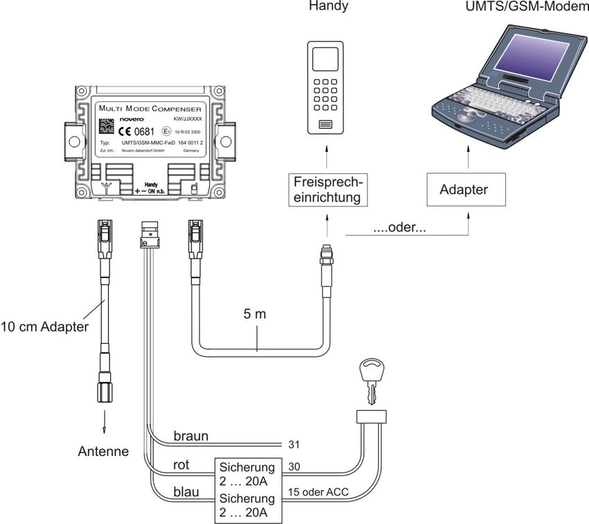
Lesen Sie die Sicherheitshinweise in diesem Handbuch auf Seite 6!

            Read the Safety Information section of this user guide on page 18!

dabendorf

novero dabendorf GmbH

Märkische Straße
D-15806 Zossen

Telefon            +49 (0) 3377316-0
Telefax            +49 (0) 3377316-300
eMail		            info.dabendorf@novero.com
Internet           www.novero-antennas.com

Änderungen im Sinne des technischen Fortschrittes und Abweichungen vom Liefe-
rumfang vorbehalten! Alle Rechte vorbehalten! Vervielfältigungen, auch auszugs-
weise, nur mit schriftlicher Genehmigung!

                                      2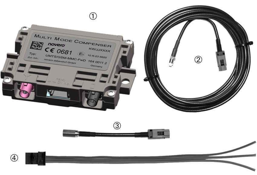
Inhaltsverzeichnis

                                                                                      Deutsch
Einführung.................................................................6
Konformitätserklärung.......................................................6
Typzulassung......................................................................6
Sicherheitshinweise..................................................6
Abklemmen des Minus-Pols der Autobatterie...................6
Bestimmungsgemäßer Einsatz...........................................6
Unsachgemäßer Einbau......................................................7
Verletzungsgefahr...............................................................7

                                                                                      English
Beschädigung wichtiger Fahrzeugteile..............................7
Kabelverlegung...................................................................7
Funktionsbeschreibung.............................................7
Lieferumfang.............................................................8
Gehen Sie beim Einbau wie folgt vor: ................................9
Nach dem Einbau................................................................9
Montage.....................................................................11
Verletzungsgefahr...............................................................11
Abklemmen des Minus-Pols der Autobatterie...................11
Einbau.......................................................................12
Unsachgemäßer Einbau......................................................12
Vorbereitungen...................................................................12
Inbetriebnahme.........................................................13
Hotline.......................................................................13
Technische Daten.......................................................14

                                                     3
Table of contents
Deutsch
Introduction..............................................................16
Declaration of Conformity...................................................16
Type approval......................................................................16
Safty Instructions......................................................16
Disconnecting the negative terminal on
the car battery....................................................................16
Intended use........................................................................16
Improper installation..........................................................17
English
Risk of injury.......................................................................17
Damage to important vehicle parts....................................17
Cable laying.........................................................................17
Function Description.................................................17
Scope of Supply.........................................................18
Function principle.....................................................19
To install the device proceed as follows:............................19
After installation.................................................................19
Installation...............................................................21
Risk of injury.......................................................................21
Disconnecting the negative terminal on the car battery....21
Installation..........................................................................22
Improper installation..........................................................22
Preparations.......................................................................22
Putting into operation...............................................23
Hotline......................................................................23
Technical Specifications............................................24
4Deutsch English
5Einführung
Vielen Dank, dass Sie sich für einen COMPENSER UMTS/GSM-MMC der Novero
Deutsch
Dabendorf GmbH entschieden haben!
Der COMPENSER sorgt in Ihrem Fahrzeug für eine optimale Sende- und Emp-
fangsleistung und damit für einen verbesserten Betrieb Ihrer GSM- und UMTS-
Endgeräte.
Konformitätserklärung
Wir, die Funkwerk Dabendorf GmbH, erklären voll verantwortlich, dass das Pro-
dukt UMTS/GSM - MULTI MODE COMPENSER den Bestimmungen der Directive
1999/5/EC des Rates der Europäischen Union entspricht.
English
Typzulassung
Die Typzulassung gemäss ECE-R10 Rev. 3 erfolgte beim Kraftfahrt-Bundesamt
unter der Nr.
10R - 03 6600
Sicherheitshinweise
Abklemmen des Minus-Pols der Autobatterie
Bei Klemmarbeiten an der elektrischen Anlage des Fahrzeugs ist grund-
sätzlich der Minus-Pol der Autobatterie abzuklemmen. Es empfiehlt sich,
den Minus-Pol auch während des gesamten Einbaus abzuklemmen.
Bestimmungsgemäßer Einsatz
Der COMPENSER ist ausschließlich für 12 V-Fahrzeuge, Minuspol an Masse
geeignet. Er gleicht die Kabelverluste der Verbindungskabel aus und ist nur
in Verbindung mit einer externen Mobilfunk-Autoantenne zu betreiben. Der
COMPENSER ist nur für den Betrieb mit GSM900/1800/UMTS-Band1-Han-
dys bzw. GSM900/1800/UMTS-Band1-PC-Card Modems zu verwenden.
6Unsachgemäßer Einbau
Unsachgemäßer Einbau kann zu Schäden am Gerät oder am Fahrzeug füh-
ren. Für den Einbau des COMPENSER´s sind spezielle Kenntnisse und Fä-
Deutsch
higkeiten erforderlich. Wir empfehlen, den Einbau in einer Fachwerkstatt
vornehmen zu lassen.
Verletzungsgefahr
Ungeeignete Einbaustellen können zu Verletzungen bei einem Verkehrsun-
fall führen oder Sicherheitseinrichtungen unwirksam machen. Bringen Sie
den COMPENSER nicht im Wirkungsbereich von Airbags an.
Beschädigung wichtiger Fahrzeugteile
Beim Bohren von Befestigungslöchern oder beim Eindrehen von Blech-
schrauben können Fahrzeugteile oder Leitungen beschädigt werden. Ach-
ten Sie auf ausreichende Baufreiheit auch hinter den Schrauben und
English
Bohrlöchern.
Kabelverlegung
Kabel dürfen im verlegten Zustand nicht auf Zug beansprucht werden. Füh-
ren Sie die Kabel so, dass sie nicht scheuern oder gequetscht werden. Beim
HF-Kabel ist ein Biegeradius von 3cm nicht zu unterschreiten!
Funktionsbeschreibung
Der COMPENSER UMTS/GSM-MMC enthält bidirektionale Sende- und Empfangs-
verstärker, jeweils für die Frequenzbereiche GSM900, GSM1800 und UMTS-Band1.
Sämtliche Kabel- und Steckerverluste, die auf dem Signalweg vom Mobiltelefon
zur Außenantenne entstehen, werden ausgeglichen. Auch Mobiltelefon-Halterun-
gen mit einem Antennenkoppler sind hier mit berücksichtigt. Dadurch wird eine
optimale Gesprächsqualität durch optimierte Sende- und Empfangseigenschaften
erreicht.
Der COMPENSER ist mit dem Anlegen einer Einschaltspannung (9V-16V) am „Han-
dy-On“-Pin betriebsbereit. Solange kein Telefongespräch geführt wird, sind nur
die Empfangsverstärker aktiv. Bei einem Telefongespräch wird zusätzlich der ent-
sprechende Sendeverstärker aktiv.
Im Standby Modus (Compenser ausgeschaltet) ist die Stromaufnahme minimal (<
0,1 mA), wodurch eine Belastung der Autobatterie vermieden wird.
7Die Einschalt-Funktion kann durch Beschalten des „Handy-On“-Anschlusses mit
Dauerplus (Bild 3, Klemme 30, +) außer Betrieb genommen werden. Der COMPEN-
SER ist dann immer eingeschaltet (ACHTUNG! Beachten Sie, dass dabei auch mit
ausgeschaltetem Motor eine Stromaufnahme von ca. 103 mA erfolgt und die Auto-
Deutsch
batterie belastet wird!).
Lieferumfang
English
Bild 1
À - MultiModeCompenser
- HF-Kabel (5m)
- Adapterkabel (10cm)
- Stromversorgungskabel (mit Stecker)
8Funktionsprinzip
Deutsch
English
Bild 2
Gehen Sie beim Einbau wie folgt vor:
Überprüfen Sie zunächst anhand der Abbildung (Bild 1), ob alle Teile vollständig
vorhanden sind. Legen Sie vor dem Einbau die erforderlichen Werkzeuge bereit.
Bestimmen Sie anhand der im Kapitel „Einbau“ beschriebenen Kriterien den Ein-
bauort und die Anschlussstellen für die Stromversorgung. Bauen Sie den COM-
PENSER dann entsprechend der Einbauanleitung in das Fahrzeug ein.
Nach dem Einbau
Klemmen Sie den Minus-Pol der Autobatterie wieder an und prüfen Sie wie im Ka-
pitel „Einbau, Inbetriebnahme“ beschrieben den ordnungsgemäßen Einbau des
COMPENSER´s.
Wir wünschen Ihnen viel Erfolg!
9Deutsch
English
Bild 3
Anschlussdarstellung, angeschlossene UMTS- oder GSM-Endgeräte beispielhaft
10Montage
Verletzungsgefahr
Deutsch
Ungeeignete Einbaustellen können zu Verletzungen bei einem Verkehrs-
unfall führen oder Sicherheitseinrichtungen unwirksam machen.
Bringen Sie den COMPENSER nicht im Wirkungsbereich von Airbags an.
Abklemmen des Minus-Pols der Autobatterie
Bei Klemmarbeiten an der elektrischen Anlage des Fahrzeugs ist
grundsätzlich der Minus-Pol der Autobatterie abzuklemmen.
Es empfiehlt sich, den Minus-Pol auch während des gesamten Einbaus
abzuklemmen.
English
Die Montage des UMTS/GSM - MULTI MODE COMPENSER´s erfolgt entspre-
chend Bild 3.
Verlegen Sie zunächst das im Lieferumfang enthaltene 5 m lange HF-Kabel zwi-
schen Mobiltelefon und COMPENSER (Anschluss ).
Achten Sie auf ein hörbares Einrasten des Steckverbinders am COMPENSER und
ziehen Sie die FME-Buchse am anderen Kabelende fest an (Drehmoment: 1 Nm).
Danach verlegen Sie das individuell angefertigte Antennenkabel zwischen COM-
PENSER und Mobilfunkantenne und ziehen den FME-Stecker am Adapterkabel
fest an (Drehmoment: 1 Nm).
Verlegen Sie nun das Stromversorgungskabel zwischen dem COMPENSER und den
Anschlussstellen. Verbinden Sie dieses an der Anschlusskabelseite entsprechend
den Farben.
Klemmen Sie zuerst die Masseleitung (braun) an die Anschlussstelle (Klemme 31),
danach die Einschaltleitung (blau) an die festgelegte Anschlussstelle (Klemme 15
oder ACC) und zuletzt die Dauerplusleitung (rot) an die festgelegte Anschlussstelle
(Klemme 30).
Bei diesen Klemmarbeiten muß der Minuspol der Autobatterie abgeklemmt sein.
Als nächstes verbinden Sie den Stromversorgungsstecker (Buchsenleiste am An-
schlusskabel) mit dem COMPENSER (er muß hörbar einrasten).
Zum Schluß gefestigen Sie den COMPENSER sicher im Fahrzeug und klemmen das
Minuskabel wieder an die Autobatterie.
11Einbau
Deutsch
Unsachgemäßer Einbau
Unsachgemäßer Einbau kann zu Schäden am Gerät oder am Fahrzeug
führen! Für den Einbau des COMPENSER´s sind spezielle Kenntnisse
und Fähigkeiten erforderlich.
Wir empfehlen dringend, den Einbau in einer Fachwerkstatt vornehmen
zu lassen.
Vorzugsweise sollte der Einbau des COMPENSER´s im Kofferraum des Fahrzeugs,
möglichst dicht an der Mobilfunkantenne, erfolgen. Der Einbau im Motorraum ist
nicht zulässig.
Der UMTS/GSM-MMC darf nicht geöffnet werden. Ein Eingriff führt zum Garantie-
verlust.
English
Wenden Sie sich bitte im Servicefall an Ihren Fachhändler bzw. an unsere Service-
abteilung (siehe Kapitel „Hotline“).
Vorbereitungen
Legen Sie zunächst den Einbauort für den COMPENSER fest. Dabei sollten die Si-
cherheitskriterien und der möglichst antennennahe Einbau in Betracht gezogen
werden.
Legen Sie jetzt die Anschlussstellen für Dauerplus (Klemme 30, +), Masse (Klem-
me 31, -) und geschaltetem Plus (Handy on) fest. Dabei müssen die Anschlussstel-
len Dauerplus und geschaltetem Plus abgesichert sein. Folgende Absicherungen
können verwendet werden:
Dauerplus: 5A Sicherungen
geschaltetes Plus: 5A Sicherungen
Für einen optimalen Betrieb ist das Antennenkabel so kurz wie möglich zu wählen.
Wenn Ihre Fahrzeugantenne bereits ein Kabel besitzt, kann dieses gegebenenfalls
gekürzt werden. Die notwendigen FME-Kabelbuchsen und Krimpwerkzeuge sind
im Fachhandel erhältlich.
Das im Lieferumfang enthaltene HF-Kabel hat einen FME-Stecker, da die meisten
Antennen einen FME-Anschluss besitzen.
Für Antennen ohne FME-Anschluss berät Sie Ihr Fachhändler über Adaptiermög-
lichkeiten.
Mobilfunkantennen mit sehr dünnem HF-Kabel (z.B. RG 174) sollten Sie möglichst
nicht verwenden, da dies besonders bei GSM1800 und UMTS zu erhöhten Verlusten
führt.
12Inbetriebnahme
Deutsch
Prüfen Sie bei nicht eingeschalteter Zündung mit einem Voltmeter an der Verbin-
dungsstelle von Anschlusskabel und Stromversorgungskabel, ob der Dauerplus
richtig angeschlossen ist (+12V zwischen rot und braun).
Bei einer eventuellen Verpolung stellen Sie die korrekte Anschlussbelegung her.
Der COMPENSER ist verpolungssicher; er erleidet dabei keinen Schaden.
Schalten Sie die Zündung ein und prüfen Sie an der Verbindungsstelle von An-
schlusskabel und Stromversorgungskabel, ob die Zündungsleitung richtig ange-
schlossen ist (+12 V zwischen blau und braun).
Stellen Sie eine Mobilfunkverbindung her und testen Sie, ob die Verbindung ein-
wandfrei funktioniert.
English
Hotline
Haben Sie Fragen oder Anregungen? Möchten Sie sich näher informieren?
Benötigen Sie Beratung und Service vor Ort? Rufen Sie uns an!
In den folgenden Zeiten steht Ihnen unsere Hotline zur Verfügung:
Montag – Donnerstag von 7.15 Uhr bis 18.00 Uhr
Freitag von 7.15 Uhr bis 16.00 Uhr
Folgende Schritte sollten Sie einhalten:
1. Prüfen Sie, ob die Einbauanleitung in allen Schritten korrekt befolgt wurde.
2. Halten Sie die Bezeichnung der verwendeten Geräte bereit (Handy, GSM-
Modul, etc.).
3. Versuchen Sie das Problem möglichst genau zu beschreiben.
Unsere Hotline können Sie unter folgenden Nummern erreichen:
innerhalb Deutschlands (kostenlos): Telefon: 0800 - 0 393 393
außerhalb Deutschlands: Telefon: +49 (0) 3377 - 316 233
+49 (0) 3377 - 316 234
Telefax: +49 (0) 3377 - 316 244
13Technische Daten
Deutsch
Betriebsspannung : 9 V ... 16 V
Stromaufnahme (bei UB = 14V)
Empfang : ca. 103 mA
Telefongespräch (im Mittel) : 110 mA … 260 mA
max. Spitzenstrom (im Sendezeitschlitz) :ca. 600 mA
Stand-by (Pin 3 = 0V) : < 0,1 mA
Frequenzbereiche (Senden / Empfang)
GSM 900 : 880 ... 915 MHz, 925 ... 960 MHz
GSM 1800 : 1710 ... 1785 MHz, 1805 ... 1880 MHz
English
UMTS-Band 1 (FDD) : 1920 ... 1980 MHz, 2110 ... 2170 MHz
Maximale Sendeleistung nach Mobilfunk- :bei GSM 900: 2 W (33 dBm)
Spezifikation am Antennenfußpunkt bei GSM 1800: 1 W (30 dBm)
bei UMTS: 0,25 W (24 dBm)
Minimale Sendeleistung nach Mobilfunk- :bei GSM 900: 3,2 mW (5 dBm)
Spezifikation am Antennenfußpunkt bei GSM 1800: 1 mW (0 dBm)
bei UMTS: 0,01 µW (-50 dBm)
Empfindlichkeit nach Mobilfunk- : bei GSM 900:
Spezifikation eingehalten bei einem Leistungs-
pegel
< -102 dBm am Antennenfuß punkt
: bei GSM 1800:
eingehalten bei einem Leistungs-
pegel
< -100 dBm am Antennenfuß punkt
: bei UMTS:
eingehalten bei einem Leistungs-
pegel
< -106,7dBm am Antennenfußpunkt
14Umgebungstemperatur für Betrieb : (-40 ... +70) °C
Deutsch
Dämpfungsausgleich für Sende- : GSM 900 je 8 dB
und Empfangsweg : GSM 1800 je 11,5 dB
: UMTS Band1 je 13 dB
Steckverbindung Stromversorgung : Mikro-Quadlok 4 polig, 1 Pol nicht
benutzt, (Pin1: 12V, Pin2: Masse,
Pin3: Einschaltleitung)
English
HF-Steckverbindung : Antennenanschluß: FAKRA Stecker
(lila Codierung D)
: Handyanschluß: FAKRA Stecker
(schwarze Codierung A)
: an den Kabelenden: FME
Gehäuse : Druckguß, HF-dicht
Abmessungen in mm (LxBxH) : 92,6 x 62,2 x 18,2
Masse : ca. 150 g
Mitgelieferter Kabelsatz : 5,0m + 0,1m RG58 mit FME-Steck-
verbindern
15Introduction
Deutsch
Thank you for choosing an COMPENSER UMTS/GSM-MMC from Novero Daben-
dorf!
The COMPENSER ensures optimum transmitting and receiving power in your ve-
hicle and therefore enhances the operation of your GSM and UMTS end devices.
Declaration of conformity
We, Novero Dabendorf GmbH, declare with full responsibility that the product
UMTS/GSM - MULTI MODE COMPENSER meets the requirements of Directive
1999/5/EC of the Council of the European Union.
English
Type approval
Type approval in accordance with Directive ECE-R10 Rev. 3, was granted at the
Kraftfahrt-Bundesamt (Federal Motor Transport Authority) under number.
10R - 03 6600
Safety unstructions
Disconnecting the negative terminal on the car battery
The negative terminal on the car battery must always be disconnected when
working with the terminals on the vehicle’s electrical system. It is advisable
to disconnect the negative terminal throughout the whole installation.
Intended use
The COMPENSER is only suitable for 12 V vehicles with a negative terminal
to ground. It compensates for the cable losses of the connecting cables and
is only to be operated in conjunction with an external mobile phone vehic-
le antenna. The COMPENSER should only be operated with GSM 900/1800/
UMTS Band I mobiles or GSM 900/1800/UMTS Band I PC card modems.
16Improper installation
Improper installation can cause damage to the device or vehicle. Specific
knowledge and skills are required to install the COMPENSER. We recom-
Deutsch
mend that the installation be carried out in a specialist workshop.
Risk of injury
Installing the device in inappropriate positions may cause injuries in a road
accident or render safety devices ineffective. Do not position the COMPEN-
SER within the effective range of the airbags.
Damage to important vehicle parts
Vehicle parts or leads may be damaged when drilling fixing holes or tighte-
ning tapping screws. Please ensure there is sufficient space, even behind
the screws and drill holes.
English
Cable laying
When laid, cables should not be subjected to strain. Lay the cables in such a
way that they do not rub against each other or become crushed. With the HF
cable, the bend radius may not lie below 3 cm!
Functional description
The COMPENSER UMTS/GSM MMC contains bidirectional transmitting and recei-
ving amplifiers for the respective frequency ranges of GSM 900, GSM 1800 and
UMTS Band I. All cable and connector losses that arise on the signal's path from
the mobile phone to the external antenna are compensated for. Even mobile phone
cradles with an antenna connection are included here. Optimum call quality is
therefore achieved, as the transmitting and receiving properties are optimised.
The COMPENSER is ready for operation as the vehicle’s ignition is switched on. If
no telephone call is in progress, only the receiving amplifiers will be active. When
a telephone call is in progress, the corresponding transmitting amplifier is also
active.
The device remains ready for operation for approx. 2 hours after the ignition is
switched off. The COMPENSER does not switch off completely until this time has
elapsed (standby); this means it can continue to be used when journeys are briefly
interrupted. Current consumption in standby mode is minimal (< 0.1 mA), thereby
avoiding load on the car battery. The COMPENSER is reactivated when the ignition
is switched back on.
The timer function can be disabled by wiring the ignition connection (Ign.) to con-
stant positive (Fig. 3, terminal 30, +). This means that the COMPENSER is always
switched on. (CAUTION! Please note that a constant current consumption of ap-
prox. 250 mA occurs in the process and a load is placed on the car battery!)
17Scope of supply
Deutsch
English
Fig. 1
À MultiModeCompenser
HF cable
ST 2.9 x 19 (DIN 7981) CH Zn mounting screws
Power supply cable
18Function principle
Deutsch
English
Fig. 2
To install the device proceed as follows:
First of all, use the illustration overleaf (Fig. 1) to check that you have all the compo-
nents. Have all the necessary tools at hand before starting installation. Referring
to the criteria described in the “Installation” chapter, determine the installation
position and the connection points for the power supply. Then install the COMPEN-
SER in the vehicle, following the instructions in the installation manual.
After installation
Reconnect the negative terminal on the car battery and check that the COMPENSER
has been installed correctly, as described in the “Installation, Putting into Opera-
tion” chapter.
Good luck!
19Deutsch
English
Fig. 3
Connection diagram, with connected UMTS or GSM end devices, as an example
20Installation
Deutsch
Risk of injury
Installing the device in inappropriate positions may cause injuries in a
road accident or render safety devices ineffective. Do not position the
ACTIVE COMBINER within the effective range of the airbags.
Disconnecting the negative terminal on the car battery
The negative terminal on the car battery must always be disconnected
when working with the terminals on the vehicle’s electrical system. It is
advisable to disconnect the negative terminal throughout the whole ins-
tallation.
English
The UMTS/GSM - MULTI MODE COMPENSER is installed as shown in Fig. 3.
First of all, install the provided 5 m HF cable between the mobile phone and the
COMPENSER (connection ).
Ensure that the connector audibly engages at the COMPENSER and tighten the FME
jack at the opposite cable end (torque: 1 Nm).
Then install the individually-prepared antenna cable between the COMPENSER and
mobile phone antenna and tighten the FME connector at the adapter cable (torque:
1 Nm).
Now install the power supply cable between the COMPENSER and the connection
points. Connect this to the connection cable side in accordance with the colours
shown.
First connect the earth lead (brown) to the connection point (terminal 31), then the
ignition lead (blue) to the fixed connection point (terminal 15) and finally the cons-
tant positive lead (red) to the fixed connection point (terminal 30).
When working with these terminals, the negative terminal on the car battery must
be disconnected.
Then connect the power supply connector (socket connector on the connection
cable) to the COMPENSER (you must hear it lock in place).
Finally, screw in the COMPENSER using the four screws provided and reconnect
the negative cable to the car battery.
21Installation
Deutsch
Improper installation
Improper installation can cause damage to the device or vehicle!
Specific knowledge and skills are required to install the COMPENSER.
We strongly recommend that the installation is carried out in a specialist
workshop.
The COMPENSER should preferably be installed in the vehicle’s boot, as close as
possible to the mobile phone antenna. Installation within the engine compartment
is not permitted.
The UMTS/GSM MMC must not be opened. Interference will render the guarantee
invalid.
English
For servicing purposes, please contact your specialist dealer or our service de-
partment (see “Hotline” chapter).
Preparations
First of all, determine where the COMPENSER is to be installed. In doing so, you
should consider the safety criteria and remember that it should be installed as
close to the antenna as possible.
Now determine the connection points for constant positive (terminal 30, +), earth
(terminal 31, -) and ignition/positive connected (terminal 15, Ign.). The connection
points for constant positive and ignition must be fused. The following fuse ratings
may be used:
Constant positive: 5A fuse
Ignition: 5A fuse
For optimum operation, the antenna cable should be kept as short as possible. If
your vehicle antenna already has a cable, this can be shortened if required. The ne-
cessary FME cable plugs and crimping tools are available from specialist dealers.
The HF cable included in the scope of supply has an FME connector as most anten-
nas have an FME connection.
For antennas without an FME connection, please ask your dealer about adapter
options.
If possible, do not use mobile phone antennas with very thin HF cable (e.g. RG 174),
as this will result in increased transmission losses, particularly with GSM 1800 and
UMTS.
22Putting into operation
Deutsch
With the ignition switched off, use a voltmeter at the connection point of the con-
nection cable and power supply cable to check whether the constant positive is
connected correctly (+12 V between red and brown).
Should the polarity be reversed, establish the correct pin assignment. The COM-
PENSER is protected against polarity reversal; the device will not be damaged.
Switch on the ignition and check at the connection point of the connection cable and
power supply cable whether the ignition lead is connected correctly (+12 V between
blue and brown).
Establish a mobile phone connection and test the connection to ensure it works
correctly.
English
Hotline
Do you have questions or suggestions to make? Are you interested in more detailed
information? Do you need advice or service locally? Simply call us!
Our hotline is at your disposal in the following times
Monday – Thursday from 7:15 hrs to 18:00 hrs
Friday from 7:15 hrs to 16:00 hrs
You should comply with the following steps:
→ Check whether you can solve your problem with the help of the section
„Trouble Shooting“.
→ Try to describe the problem as precisely as possible.
You can contact our hotline under the following numbers:
within Germany, [free of charge]: Telephone: 0800 – 0393 393
outside Germany: Telephone: +49 [0] 3377 – 316 233
+49 [0] 3377 – 316 234
Facsimile: +49 [0] 3377 – 316 244
23Technical specifications
Deutsch
Operating voltage : 9 V ... 16 V
Current consumption (at UB = 13V)
Reception : approx. 250 mA
Telephone call (average) : 260 mA … 400 mA
Max. peak current
(in the transmitting slot) : approx. 1,6 A
Stand by (after 2 hrs. with timer) : < 0,1 mA
Frequency range (Transmissio/Reception)
GSM 900 : 880 ... 915 MHz, 925 ... 960 MHz
English
GSM 1800 : 1710 ... 1785 MHz, 1805 ... 1880 MHz
UMTS-Band 1 (FDD) : 1920 ... 1980 MHz, 2110 ... 2170 MHz
Maximum transmitting power in
acc. with mobile : with GSM 900: 2 W (33 dBm)
phone-specification at the base
of the antenna with GSM 1800: 1 W (30 dBm)
with UMTS: 0,25 W (24 dBm)
Minimum transmitting power in
acc. with mobile : with GSM 900: 3,2 mW (5 dBm)
phone-specification at the base
of the antenna with GSM 1800: 1 mW (0 dBm)
with UMTS: 0,01 µW (-50 dBm)
Sensitivity in acc. with mobile phone- : with GSM 900:
specification maintained with a power level
< -102 dBm at base of the antenna
: with GSM 1800:
maintained with a power level
< -100 dBm at base of the antenna
: withUMTS:
maintained with a power level
< -106,7dBm at base of the antenna
24Ambient temperature for operation : (-40 ... +70) °C
Deutsch
Attenuation compensation for
transmitting and receiving path : GSM 900 Per 8 dB
: GSM 1800 Per 11,5 dB
: UMTS Band1 Per 13 dB
Plug connection on the power supply : Micro Quadlok 4-pin, 1 pin not
used, (Pin 1: 12 V, Pin 2: ground,
English
Pin3: ignition)
HF-plug connection : Double FAKRA connector (coding A)
Gehäuse : Druckguß, HF-dicht
Housing : Diecast, impervious to HF
Dimensions in mm (L x W x H) : 110 x 84 x 23
Mass : approx. 250 g
Cable set provided : 5,0m + 0,25m RG58 mit FME-Steckver
bindern
2526
27
novero dabendorf GmbH

Märkische Straße
D-15806 Zossen

Telefon    +49 (0) 3377 316 - 0
Telefax    +49 (0) 3377 316 - 300
eMail      info.dabendorf@novero.com
			        service.dabendorf@novero.com
Internet   www.novero-antennas.com        dabendorf
Sie können auch lesen