SARTOFLOW Alpha plus SU - Operating Manual | Bedienungsanleitung 85032-537-29
←
→
Transkription von Seiteninhalten
Wenn Ihr Browser die Seite nicht korrekt rendert, bitte, lesen Sie den Inhalt der Seite unten
Operating Manual | Bedienungsanleitung

SARTOFLOW® Alpha plus SU
Crossflow Filtration System | Crossflow-Filtrationssystem

                                       85032-537-29         Vers. 10 | 2012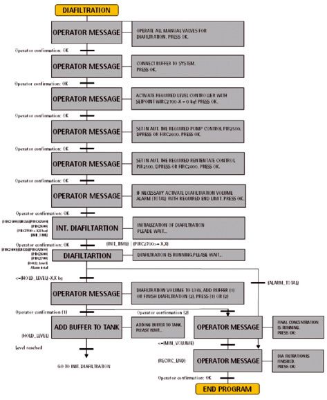
Auf der beiliegenden CD befindet sich die Bedie-        The enclosed CD contains the operating instructions
nungsanleitung für SARTOFLOW® Alpha plus SU             for SARTOFLOW® Alpha plus SU as a PDF file in
als PDF-File in deutscher, englischer, französischer,   German, English, French, Spanish and Italian.
spanischer und italienischer Sprache.
                                                        Further languages on request.
Weitere Sprachen sind auf Anfrage erhältlich.
                                                        If the CD is missing, you can obtain a copy form
Sollte die CD fehlen können Sie diese unter Angabe      us by specifying the order number:
der Bestellnummer bei uns beziehen:                     Order number: 85032-537-47
Bestellnummer: 85032-537-47                             Publication number: SPC6041-p
Publikationsnummer: SPC6041-p

                                                        Sartorius Stedim Biotech GmbH
Sartorius Stedim Biotech GmbH                           Technical Editorial Department
Technical Editorial Department                          August-Spindler-Strasse 11
August-Spindler-Strasse 11                              37079 Goettingen, Germany
37079 Goettingen, Germany
                                                        tech.pubs@sartorius-stedim.com
tech.pubs@sartorius-stedim.com                          www.sartorius-stedim.com
www.sartorius-stedim.com

                                                        System requirements:
Systemvoraussetzungen:                                  Windows® XP or higher
Windows® XP oder höher                                  Adobe® Reader® 5.0 or higher
Adobe® Reader® 5.0 oder höher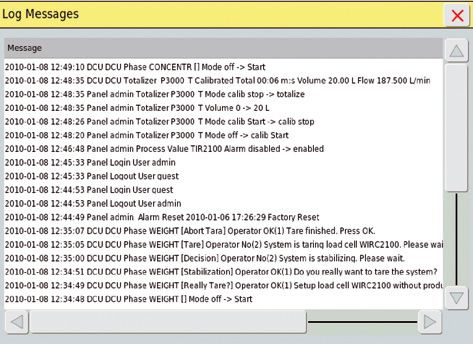
Contents of this Manual |
Inhalt dieser Anleitung
English . . . . . . . . . . . . . . . . . . . . . . . . . . . . . . . . . . . . . . . . . . . . . . . Page 5
Deutsch . . . . . . . . . . . . . . . . . . . . . . . . . . . . . . . . . . . . . . . . . . . . . . Seite 47

If you require further information on crossflow filtration, other than mentioned in
this User Manual, please contact us.
Reproduction, translation and duplication in any form, in part or in full, requires
the written permission of the Sartorius Stedim Biotech GmbH.

For technical information write to:

Sartorius Stedim Biotech GmbH
August-Spindler-Strasse 11
D-37079 Goettingen
Internet: www.sartorius-stedim.com

Edition: June 2010
Ordernumber: 85032-537-29

Wenn Sie verbindliche Informationen zu bestimmten Eigenschaften Ihrer Crossflow
Cassetten benötigen, welche über die hier beschriebenen hinaus gehen, bitten wir um
Ihre Anfrage.
Nachdruck, Übersetzung und Vervielfältigung in jeglicher Form, auch auszugsweise,
bedürfen der schriftlichen Genehmigung der Sartorius Stedim Biotech GmbH.

Adresse der Technischen Dokumentation:

Sartorius Stedim Biotech GmbH
August-Spindler-Strasse 11
D-37079 Göttingen
Internet: www.sartorius-stedim.com
Germany

Version: Juni 2010
Bestellnummer: 85032-537-29

                                                                                                               3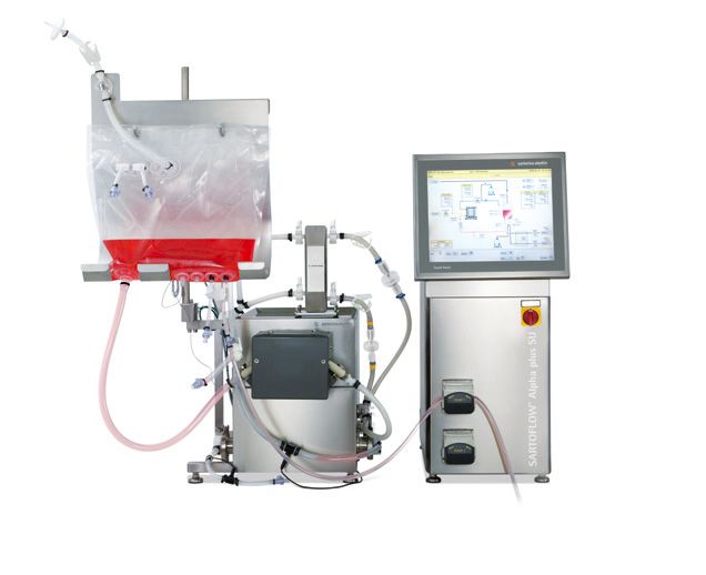
4
Contents
1. Structure and Application . . . . . . . . . . . . . . . . . . . . . . . 10              3. Operation of the Filtration System . . . . . . . . . . . . . . . . 23
   1.1   General Notes . . . . . . . . . . . . . . . . . . . . . . . . . . . . 10             3.1   Starting the Unit | Emergency Stop Function . . . 23
   1.2   System Structure . . . . . . . . . . . . . . . . . . . . . . . . . 10                3.2   Display . . . . . . . . . . . . . . . . . . . . . . . . . . . . . . . . . . . 23
                                                                                              3.2.1 Touch Fields of the Start Screen . . . . . . . . . . . . . . 23
2. Installation and Starting Up . . . . . . . . . . . . . . . . . . . . . . 12                3.3   Modes of Operation . . . . . . . . . . . . . . . . . . . . . . . . 24
   2.1     In General . . . . . . . . . . . . . . . . . . . . . . . . . . . . . . . . 12      3.3.1 Manual Operation . . . . . . . . . . . . . . . . . . . . . . . . . 24
   2.1.1 Assembly Surface . . . . . . . . . . . . . . . . . . . . . . . . . . 12              3.3.2 Semi-Automatic Operation . . . . . . . . . . . . . . . . . . 24
   2.1.2 Preparation of the Workplace . . . . . . . . . . . . . . . . 13                      3.3.3 Menu Bar . . . . . . . . . . . . . . . . . . . . . . . . . . . . . . . . . 24
   2.2     General Connections and
                                                                                           4. Appendix . . . . . . . . . . . . . . . . . . . . . . . . . . . . . . . . . . . . . . . 41
           Installation Material of the Filtration Module . . . 13
                                                                                              4.1  Technical Data . . . . . . . . . . . . . . . . . . . . . . . . . . . . 41
   2.2.1 Mains Supply . . . . . . . . . . . . . . . . . . . . . . . . . . . . . . 13
                                                                                              4.2  Cleaning and Care . . . . . . . . . . . . . . . . . . . . . . . . . 41
   2.2.2 Communication (Ethernet) . . . . . . . . . . . . . . . . . . 13
                                                                                              4.3  Maintenance and Service . . . . . . . . . . . . . . . . . . . 41
   2.2.3 Sewage Discharge . . . . . . . . . . . . . . . . . . . . . . . . . . 13
                                                                                              4.4  Causes of Malfunction . . . . . . . . . . . . . . . . . . . . . . 42
   2.2.4 Discharged Air | Ventilation . . . . . . . . . . . . . . . . . . 13
                                                                                              4.5  Disassembly and Disposal . . . . . . . . . . . . . . . . . . . . 43
   2.3     DCU4 Tower . . . . . . . . . . . . . . . . . . . . . . . . . . . . . . . 14
                                                                                              4.6  Warranty . . . . . . . . . . . . . . . . . . . . . . . . . . . . . . . . . 44
   2.3.1 Structure of the DCU4 Tower . . . . . . . . . . . . . . . . 14
                                                                                              4.7  EC Declaration of Conformity . . . . . . . . . . . . . . . . 44
   2.3.2 Installation and Alignment of DCU4-Tower . . . . 14
                                                                                              4.8  Declaration of Decontamination . . . . . . . . . . . . . 44
   2.3.3 Signal and Power Supply of the DCU4 Tower . . . 15
                                                                                              4.9  Contact Addresses . . . . . . . . . . . . . . . . . . . . . . . . . 44
   2.4     Filtration Unit . . . . . . . . . . . . . . . . . . . . . . . . . . . . . 15
                                                                                              4.10 Information and Instructions on Disposal . . . . . . 45
   2.4.1 Structure of the Filtration System . . . . . . . . . . . . 15
   2.4.2 Assembly and Alignment of Filtration Unit . . . . . 16
   2.4.3 Inspection of the filtration unit . . . . . . . . . . . . . . 16
   2.4.4 Signal and Power Supply of the Filtration Unit . . 17
   2.4.5 Mounting of the Recirculation Container
           (Bag as Recirculation Container) . . . . . . . . . . . . . . 17
   2.4.6 Installation of the presterilized Single use
           Crossflow Loop . . . . . . . . . . . . . . . . . . . . . . . . . . . . 18

                                                                                                                                                              Contents               5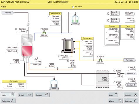
Introduction                       Introduction
                                   This operating manual describes the installation and commissioning, the connection
                                   of the energy | supply modules as well as the operation of a SARTOFLOW® filtration
                                   system.

                                   Information on the different components you can find in the external operating
                                   manuals.

Application of the                 The SARTOFLOW® filtration system is suited for the continuous filtration of
SARTOFLOW® Filtration System       suspensions and liquid media within the laboratory and production scale.
                                   By using different kinds of Self Contained Units the filtration system can be used for
                                   microfiltration as well as for ultrafiltration purposes.

                                   For special processes the use may be permitted only under certain circumstances.
                                   As concerns e. g. the biological safety there are special requirements on the
                                   workplace, the instrumentation, the handling of the components, the safety of the
                                   personnel and the work environment. This operating manual does not specify such
                                   requirements and other regulations which are obligatory by law or otherwise.

                                   The operating of the filtration system requires the usual knowledge of an expert for
                                   the handling of micro organisms, cells and contaminated items. If there are special
                                   risks for users and the working environment at the handling of components, the
                                   operating manual contains danger, warning, caution and safety notes. They apply in
                                   addition to the regulations for the use at the workplace.

                                   The SARTOFLOW® filtration system has been designed for stationary operation
                                   purposes only.

Signs and symbols                  Danger notes bear the preceding symbol and they are marked in red colour.
                                   If you disregard these danger notes damages of the equipment or other material
                                   damages or personal injury with a high risk may result.

                                   Notes of warning bear the preceding symbol and they are marked
                                   in orange colour.
                                   If you disregard these notes of warning damages of the equipment or other
                                   material damages and personal injury with a medium risk may result.

                                   Caution notes bear the preceding symbol and they are marked in yellow colour.
                                   If you disregard these caution notes damages of the equipment or other
                                   material damages and personal injury with a low risk may result.

                                   Safety notes and general notes bear the preceding symbol.
                                   It identifies all steps which have to be carried out with extreme care.
                                   It appears if special aspects have to be considered.

                               t   The refers to any information included in this or in other documents.
                                   The brackets specify the sources of figures, paragraphs or documents.

                               §   These paragraphs contain operating steps which have to be carried out one after
                                   another.

6       Introduction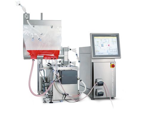
Introduction                  The SARTOFLOW® microfiltration or ultrafiltration system is a part of the product
                              program of Sartorius Stedim.
                              If you have any questions concerning this system or the rest of the product program
                              of Sartorius Stedim you can contact the following address.

                              Sartorius Stedim Systems GmbH
                              Robert-Bosch-Str. 5–7
                              D - 34302 Guxhagen, Germany
                              Phone: +49.5665.407.0
                              Fax: +49.5665.407.2201

Notes to this documentation   All information on the SARTOFLOW® filtration system refers to the time of the
                              publication of this document. We reserve the right to modify different components of
                              the filtration system compared with the information and modifications of this docu-
                              ment without separate notice. Third parties are not allowed to alter the operating
                              manual in some way without our previous written authorization. The same applies to
                              the copying or the use of the document for other purposes.

                                                                                               Introduction         7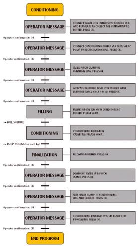
Safety notes
General notes              Please note:
                           – The operators must be technically qualified for the field of application and they
                              must be familiar with the handling of the unit and the resulting dangers.

                           – Your company must hang up safety regulations on existing dangers. They must
                             be visible (at the application) for the employees and the work environment at the
                             place of assembly. If necessary suitable safety devices have to be provided.

                           – It is generally necessary to wear suited work wear and personal protective equip-
                             ment such as gloves, protective goggles and eventually a breathing protection.

                           – Unauthorized employees are not allowed to work at the unit.

Notes for the save use     Please note:
of the filtration system   – At the work at and with the SARTOFLOW® filtration system you only have to use
                              such devices and peripheral devices which have been released for this kind of use
                              by Sartorius Stedim.

                           Risk!
                           Be very careful when handling with the recirculation bag. You may injure or
                           unintentionally spill the media.

                           – If modifications are carried out at the filtration system you have to handle the
                             recirculation system with care. Please check the proper condition of all parts before
                             using them. Damaged parts must not be installed.
                             Optionally mounted parts, external connections and components have to be
                             fastened carefully and protected from loosening unintentionally.

                           – Please take care of the weight and the required space of the components.
                             The installation surface must be able to carry the completely equipped filtration
                             system t „see chapter 2.1.1 |2.1.2“. You have to use suitable transport aids for the
                             transport to the installation location and for relocations.

                           – Ensure that the supply voltage as well as any other supply powers correspond with
                             the device specifications t „see chapter 2.3.3, chapter 4.1“.

8       Safety notes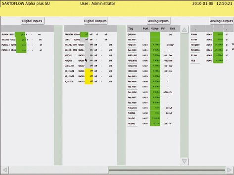
Notes for the save operation   Please note:
of the SARTOFLOW®
filtration system
                               Risk of breakage or bursting!
                               You must charge the recirculation bag only with the maximum pressure
                               of 300 mbar.

                               At all plastic or similar materials (e. g. bags) it is not recommended to use pointy
                               items (scissors, knife, screwdriver etc.) since they may break.

                               – The SARTOFLOW® filtration system must only be operated with the admissible
                                 energies (power supply) and the provided performance data.

                               – The technical data are described in a separate chapter
                                 t „see chapter 4.1“ of the operating manual.

                               – You must always control the processes if critical situations may occur. You must
                                 make arrangements in order to avoid any dangers or damages due to process
                                 disturbances.

                               – t „After finishing the filtration process and before any maintenance works you
                                 have to observe the safety regulations for contaminated devices“.

                               Interventions and technical modifications at the DCU4 tower, the control
                               modules, the supply modules, the drive modules, the vessels and the peripheral
                               devices as well as at all adapters for the connection to the peripheral devices are
                               not allowed if you have not been authorized by Sartorius Stedim Systems GmbH.

Safety notes                   – Only authorized persons are allowed to carry out service and repair works. You
                                 must only use spare parts which have been released for the existing SARTOFLOW®
                                 filtration system by Sartorius Stedim Systems GmbH.

                                                                                                Safety notes        9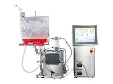
1. Structure and Application        1. Structure and Application
1.1 General Notes                   The SARTOFLOW® Alpha plus SU filtration system has been designed for Single use
                                    applications as well as for the use at the production of small volumes. The automati-
                                    cally mode of operation of the SARTOFLOW® Alpha plus SU filtration system guaran-
                                    tees repeatable results.

                                    SARTOFLOW® Alpha plus SU can be equipped with a gamma presterilized loop. All
                                    product-contact surfaces like self contained UF|MF unit, pressure domes, flow
                                    meters, valves, bags, sterile connectors and tubing support a maximum of flexibility
                                    and process security.

                                    The SARTOFLOW® Alpha plus SU is particularly suitable for contract manufacturers,
                                    research and development applications, small scale production cycles and companies
                                    with frequently changing productions.

1.2 System Structure                The SARTOFLOW® Alpha plus SU consists of the following:

                                    No. Modules                                    Description
                                    1     SARTOFLOW® Alpha plus SU                 Filtration unit with standard
                                          filtration unit with standard            instrumentation, and bag stand.
                                          filter holder                            Manual filter holder
                                    2     SARTOFLOW® Alpha plus SU                 Filtration unit with standard
                                          filtration unit with hydraulic           instrumentation, and bag stand.
                                          filter holder                            Hydraulic filter holder
                                    3     DCU4 Tower
                                          230 VAC|60 Hz
                                    4     DCU4 Tower
                                          120 VAC|50 Hz

                                    Consumables
                                    Order number          Description
                                    SFA-SU-1463901        UF 10 kDa PESU, 0.1 m2 components of bag assembly:
                                    SFA-SU-1463921        UF 10 kDa PESU, 0.2 m2 10 l recirculation bag, pressure domes,
                                                                                 flow meters, valve bodies,
                                    SFA-SU-1463931        UF 10 kDa PESU, 0.3 m2 OPTA connectors and tubing
                                    SFA-SU-1465901        UF 30 kDa PESU, 0.1 m2
                                    SFA-SU-1465921        UF 30 kDa PESU, 0.2 m2
                                    SFA-SU-1465931        UF 30 kDa PESU, 0.3 m2
                                    TBD                   MF 0.1 μm PESU, 0.1 m2
                                    TBD                   MF 0.1 μm PESU, 0.2 m2
                                    TBD                   MF 0.1 μm PESU, 0.3 m2

10      Structure and Application
2
1
Figure 1-1: SARTOFLOW® Alpha plus SU
1. Hardware: DCU4 control tower, Filtration unit with standard instrumentation,
filter holder and bag stand.
2. Gamma presterilized Loop consisting of Self Contained Unit MF or UF,
recirculation bag, pressure domes, flow meters, valves, OPTA sterile connectors
and tubing.
Structure and Application 112. Installation and Starting Up 2. Installation and Starting Up
2.1 In General The SARTOFLOW® Alpha plus SU filtration unit is supplied to the customer after
a thorough functional check.
In case the SARTOFLOW® Alpha plus SU filtration unit should have been damaged
during the transport or after the delivery and installation you have to pay attention
to the following details due to eventual warranty claims (and also due to other
defects).
– Check the completeness of the supplied material according to your order.
– Thoroughly check all components for damages.
– Report the missing parts or any transport damages to your local representation of
Sartorius Stedim Systems GmbH or to Sartorius AG.
– Please check the operability of the SARTOFLOW® Alpha plus SU filtration unit
before starting the first filtration process. Please thoroughly record eventual
malfunctions. A record may facilitate you and Sartorius the handling of eventual
claims.
2.1.1 Assembly Surface The lower figure shows the SARTOFLOW® Alpha plus SU as complete unit with the
minimum external dimensions.
All dimensions in mm.
L
1200
L
96
0 M
M
M
1300
L
Figure 2-1: External dimensions of the SARTOFLOW® Alpha plus SU
12 Installation and Starting Up2.1.2 Preparation of the Workplace The installation location must be suited for the filtration system. The installation loca-
tion must offer enough space and the bottom must be able to carry the weight
of the completely equipped unit.
– When installing the SARTOFLOW® Alpha plus SU you must take care for sufficient
space for the connection to the laboratory devices as well as other necessary
modules.
Check the correct dimensioning of the following connections:
– Mains voltage.
2.2 General Connections
and Installation Material
of the Filtration Module
2.2.1 Mains Supply
Voltage damage!
The connection to a wrong power supply may lead to damage of the unit.
Before starting the device the correct power supply has to be checked carefully.
Check at the type plates of the systems components supplied to you if the
voltage type is correct and if the power cables are provided with the right plug
necessary for your kind of use.
If you have got a wrong voltage type or a power cable with wrong plugs,
please contact your customer service at Sartorius Stedim Systems GmbH.
The DCU4 tower of the SARTOFLOW® Alpha plus SU is available in two
voltage types.
230 volts (±10 %), 50|60 Hz
or
110 volts (±10 %), 50|60 Hz
2.2.2 Communication (Ethernet) In order to communicate with superior central computer systems (SCADA)
the SARTOFLOW® Alpha plus SU has got an Ethernet connection in the DCU4
tower module.
2.2.3 Sewage Discharge The discharge of sewage is carried out by means of respective connections (part of
presterilized Loop).
2.2.4 Discharged Air | Ventilation The pressure equalization within the filtration unit is carried out by means
of a ventilation device (part of presterilized Loop).
Installation and Starting Up 132.3 DCU4 Tower
2.3.1 Structure of the DCU4 Tower The „DCU4 tower“ serves as digital measurement and control system which
is connected to the filtration unit.
t „Technical description: see external operating manual „DCU4 Tower“.
1
2
3
3
Figure 2-2: Front view of the DCU4 tower
1. Touch panel
2. Main switch
3. Peristaltik pump 1 + 2
2.3.2 Installation and Alignment The DCU4 tower is provided with height adjustable feet for the alignment.
of DCU4-Tower
Carefully level the DCU4 tower before you start it up.
1
Figure 2-3: Feet of the DCU4 tower
1. Height adjustable feet (4 pieces)
Please proceed as follows in order to level the DCU4 tower:
§ Loosen the counter nuts of the feet.
§ Carefully level the DCU4 tower by turning the feet out or in.
§ Fasten the counter nuts of the feet.
14 Installation and Starting Up2.3.3 Signal and Power Supply For the signal and power supply the DCU4 tower has got the connections
of the DCU4 Tower described as follows.
They are on the back side of the DCU4 tower.
5 4
3
6 2
1
Figure 2-4: Signal and power supply of the DCU4 tower (rear view)
1. Main supply
2. Power supply of the recirculation pump
3. Connections for digital signals and 24 volts power supply of the filtration unit
4. Connections for analog signals of the filtration unit
5. Ethernet connection
6. External 4–20 mA Signal
2.4 Filtration Unit
2.4.1 Structure of the Filtration System The filtration unit mainly consists of the following single components:
7
10
6
9
8 1
11
4 12
5
2
3
13
14
Figure 2-5: Front view of the filtration unit Figure 2-6: Side view of the filtration unit
1. Retentate connection 6. Recirculation bag 10. Over pressure protection (Bag)
2. Recirculation pump 7. Air-filter 11. Temperature sensor
3. Pressure transducers 8. Filter holder 12. Load cell
4. Feed line 9. Permeat connection 13. Flow meter in the retentate line
5. Feed connection 14. Flow meter in the permeate line
Installation and Starting Up 152.4.2 Assembly and Alignment The filtration unit is provided with height adjustable feet for the alignment.
of Filtration Unit
Carefully level the filtration unit before you start it.
1 1
Figure 2-7: Feet of the filtration unit
1. Height adjustable feet (4 … 6 pieces)
For the alignment of the filtration unit please proceed as follows:
§ Loosen the counter nuts of the feet.
§ Level the filtration unit by turning the feet in or out.
§ Fasten the counter nuts of the feet.
2.4.3 Inspection of the filtration unit Before you start the filtration system you have to carry out the following inspections:
§ Inspection of the tubing of the complete system.
§ Inspection of all connections and seals (if visible).
§ Inspection of all electrical cable connections at the measuring sensors
(flow meter).
16 Installation and Starting Up2.4.4 Signal and Power Supply The filtration unit is provided with respective connecting lines for the signal and
of the Filtration Unit power supply.
(t „Connector pin assignment at the DCU4 tower“ see chapter 2.3.3)
5
1
6 3 4
2
Figure 2-8: Signal and power supply filtration unit
1. Main supply
2. Power supply of the recirculation pump
3. Connections for digital signals and 24 volts power supply of the filtration unit
4. Connections for analog signals of the filtration unit
5. Ethernet connection
6. External 4–20 mA Signal
2.4.5 Mounting of the The bag stand is assembled at a weight measuring system (e. g. load cell).
Recirculation Container The recirculation bag is hung up at the bag stand.
(Bag as Recirculation Container)
Load cells are very precise weighing devices. For the mounting and the handling
of the load cells please observe:
– The load cell must not be exposed to torsion.
– The maximum bearing force of the load cell must not be exceeded during
mounting and operation.
– Incorrect handling and | or mounting may lead to damage of the load cell.
The bag stand is screwed directly at the weighing device (load cell).
2
3 1. Weighing device (load cell)
2. Bag stand
3. Recirculation Bag
1
Figure 2-9: Bag stand for the recirculation bag
Installation and Starting Up 17Bag Stand installation The weighing device is equipped with a welded fastener. The bag stand is directly
screwed over it at the weighing device (load cell).
For the assembly of the bag stand please proceed as follows:
§ Apply the bag stand with the fastener at the screw-down surface of the load cell.
§ Screw down the bag stand with the provided socket screws (4 pieces)
at the load cell.
2.4.6 Installation of the presterilized When unpacking the components please check whether the packaging is intact
Single use Bag Loop and no damage to the individual components is visible. Also, make sure that during
the installation no parts are being damaged or contaminated.
Procedure 1. Installation of Self Contained Unit following the instructions listed below.
2. Hang the recirculation Bag on the Bag holder and mount pressure sensor
on Bag holder.
3. Install the Pump element in the peristaltic pump.
4. Mount the Feed pressure sensor.
5. Connect Feed line to filter element using OPTA.
6. Connect Retentate line to filter element using OPTA.
7. Mount the Retentate pressure sensor.
8. Mount the Retentate valve body.
9. Mount the Retentate flow sensor.
10. Connect Permeate line to filter element using OPTA.
11. Mount the Permeate pressure sensor.
12. Mount the Permeate valve body.
13. Mount the Permeate flow sensor.
Further instructions see below
Pressure sensor 1. Remove the membrane Protection element from the locator on the
pressure sensor.
2. Mount the open locator together with the pressure dome on the pressure
transducer. It is important to ensure that the locator is aligned as shown
in Figure 1. By applying light pressure on the two bars the gap is expanded and
the pressure dome reaches into the groove of the transducer for fixation.
3. Turn the locator to 90 degrees – shown in Figure 2
Figure 1 Figure 2
18 Installation and Starting UpElectronic positioning valve – 1. During assembly of the valve body, the electronic positioning valve must be
Valve body installation in the position “100%”.
2. Mount the Valve body to the connector (see Figure 3).
3. Fasten the Valve with Tri-clamp (see Figure 4).
4. The connection in between the actuator and the valve body is established
by moving the actuator into the position ”0%”.
Figure 3 Figure 4
Flow sensor 1. The sensor mounted on the flow cell as shown in Figure 5.
Figure 5
Installation of the Pump element 1. Lay the double y-tube element into the open pump head and place the branches
over the fixing screws.
2. Close the lid. It might be helpful to use a wrench (SW10).
Figure 6
Installation and Starting Up 19Installation of the
Sartocon Slice Self Contained
Before the assembly and cleaning of the filter holder you must carefully read
the operating manual of the Sartocon Slice Self Contained Unit! In the case of
incorrect handling of the filter cassettes severe injuries may result or the filter
cassette may be damaged.
You must only use the provided torque wrench or the hydraulic assembly
to clamp the Self Contained Unit!
- Incorrect handling may result cassette damage.
Keep the stud bolts and screw nuts clean and free of grease!
Greased or polluted threads lead to wrong clamp forces which may destroy
the cassettes.
For the installation or change of the filter cassettes follow the instructions
in „Sartocon Slice Self Contained Unit “[1], see bibliography at the end
of the chapter.
1. Install the Self Contained unit in the filter holder and clamp it with the
recommended torque, or with the appropriate hydraulic pressure.
Figure 7
– Tighten the Cassette with the recommended clamping force according to the
selected clamping device.
– When installing the Cassette make sure that the grooves are in correct orientation
(to accommodate the upper and lower rod sites).
– Keep the threads of the rods clean (avoid grease).
Do not forget hydraulic clamping the upper locking bars | rods
Clamping force for Sartocon® Slice Self Contained
Sartocon® Slice Self Contained Holder
Clamping force Clamping force
Operating parameters Operating parameters
Torque wrench
Sartocon® Slice Self Contained 14–17 kN 20 Nm
20 Installation and Starting UpOPTA-Connector 1. Connect the female and male OPTA connectors with the same colour tag.
These colour codes ensure the correct allocation of the ports.
Orange: Feed
Blue: Retentate
Yellow: Permeate
Making the Connection
Male connector Female connector
Step 1 Remove the protective caps by pulling on the flaps that are located at the bottom
of each cap. After removal of the caps membrane tapes will be released. These
membrane tapes should always hang down to assure the correct assembly of the
male and female connector bodies.
Male connector Female connector
Step 2 Retract the collar that is fixed on the female connector to prepare for assembly.
Assemble the two connectors by sliding the two connector heads together until the
two pins of the male connector click into place. Once the female and the male con-
nectors are assembled they should not be disassembled. The integrity of the male and
female connectors is ensured by the membrane sterile barrier. Each membrane tape is
equipped with a mating gripper to assure simultaneous removal of the sterile barrier.
“Click”
Installation and Starting Up 21Step 3 After the two pins of the male connector are “clicked” into place, join the grippers
at the bottom of each membrane tape together. The grippers should also “click” into
place. Remove the membrane horizontally.
Pins
Click
Grippers
Step 4 (A) Slide the collar that has been retracted back in place and (B) turn it clockwise until
the lock “clicks” into place.
(A)
(B)
“Click”
Once the cassette and the assembly is connected we recommend to flush
the loop.
Flushing – Fill the recirculation bag with 5l of sterile water (WFI).
Retentate and Permeate valves are fully open.
Set delta P to a value of 1 bar.
Flushing the system to the drain.
Refill the recirculation bag with 10l of sterile water (WFI) and pause for 15 min.
Set delta P to a value of 1 bar.
– Restrict the retentate to an extent that a ratio between the Permeate flux to
Retentate of 1:1:
Discard the permeate and retentate
22 Installation and Starting Up3. Operation of the
Filtration System 3. Operation of the Filtration System
3.1 Starting the Unit |
Emergency Stop Function
1 1. Main switch
Figure 3-1: Main switch
Before you start the unit you have to read chapter 2 „Installation and
Starting-up“ carefully.
For the starting of the unit you must proceed as follows:
1. Turn the main switch (pos. 1) to position “1” (vertical switch position).
2. Await the system start (starting-up of the unit).
In the case of eventual alarms you have to proceed as described in chapter 3.3.3
“Menu Bar → „Alarms“.
3.2 Display For the operation of the touch panels you must not use pointy items
(e. g. pens etc.).
For the cleaning of the touch panel you must only use suited cleaning agents.
3.2.1 Touch Fields After starting the unit the start screen (entry screen) shows the following windows:
of the Start Screen
Figure 3-2: Start screen of the SARTOFLOW® Alpha plus SU
Operation of the Filtration System 23The start screen is divided into the following frames:
1. Menu bar: The menu bar serves for the selection of the main menus
(main, trend, settings, remote, alarm, calibration etc.).
2. Main window: Graphic of the process including all process values as well as
the parameters of the control cycles.
3.3 Modes of Operation
3.3.1 Manual Operation This mode of operation allows a free configuration of all parameters (e. g. controller
settings, alarms etc.) considering the permissible performance data (see chapter 4.1).
3.3.2 Operation It leads the user step by step through the configuration of the parameter settings
needed for the selected sequence.
3.3.3 Menu Bar
By pressing the button „Main“ the display in the main window changes to the display
of the process. Here all process values as well as the control and alarm parameters
are indicated.
The „Main“ menu can always be accessed from all menus and submenus.
The main display represents the active process. The indicated process values can be
read off completely.
All settings relevant to the process (controller settings, process values) are controlled
via the main display.
24 Operation of the Filtration SystemSetting of the controller parameters
By pressing the button the display in the lower help window changes to the display
where the controller values are entered.
Entry of the mode of operation „auto“, „manual“, „off“
Set value display
Actual value display
Controller exit
Entry of the controller value
PID parameters (controller parameters)
Enter the alarm low and high limits
Setting of the process values
By pressing the button the display in the help window at the bottom changes to the
display where the process limit values are entered.
Enter the alarm high limit
Actual value display
Enter the alarm low limit
Switch on | off alarm
Operation of the Filtration System 25Calibration of peristaltic pumps – P3000 & P3100
By pressing the button “P3000_T”, the display changes
Press the ‘off’ Button the display changes.
Insert tubing in the peristaltic pump. Use a glass cylinder to measure
the pumped volume.
The calibration starts after you press ‘CALIBTATE’ in the next window.
By pressing OK the calibration stops.
Enter the measured the volume.
Confirm by pressing OK.
26 Operation of the Filtration SystemCalibration of flow meter
By pressing the button “Calibration”, the display changes and the phase for flow
meter calibration starts.
Calibration values are displayed for Retentate and Permeate.
Enter the calibration factor k that is delivered with the disposable part.
The calibration factor k for the installed turbine is adjusted and confirmed
by pressing OK.
Tare function and Phases
By pressing the button Tare Pressure or Weight, the display changes and the phase
for zero point tarring starts.
Further information Chapter: Phases
Operation of the Filtration System 27Trend
By pressing the „Trend“ button the display in the main window changes to the display
of the trend. Here all process values are represented as a chronological sequence.
The „Trend“menu can always be accessed from all menus and submenus.
Settings at controller parameters and process values are not possible
at this representation.
3
2
1
Figure 3-4: Trend display of the SARTOFLOW® Alpha plus SU
1. History (time)
2. Display of the process value size depending on the set scale
3. Select button (configurable)
Configuration of select button
By pressing the button an additional window appears in the trend display.
Here you find characteristics which can be assigned to the button after the
respective selection.
28 Operation of the Filtration SystemSelection of the process value to be represented
Selection of the colour of the trend line
Determine scale of the process value
Determine scale of the process values to the factory setting
Settings
All system parameters, system settings etc. can be modified at the menu point
“Settings”. After pressing the button “Settings” the submenu points are displayed on
the main window.
Any settings and modifications must only be carried out by instructed
and authorized persons as well as by the service personnel of Sartorius Stedim
Systems GmbH.
Incorrect settings may cause errors or damages of the unit and may lead to
eventual resulting accidents.
1 2 3
4 5
6
Figure 3-5: Trend display of SARTOFLOW® Alpha plus SU
1. System parameters
2. PV ranges
3. External
4. Manual Operation
5. Trend
6. Service
Operation of the Filtration System 29Settings of the system parameters (e. g. time, date, IP address etc.)
By pressing the button „system parameters“ the display in the main window changes
to the display where the values are entered.
Settings of the. time, date, IP address etc.
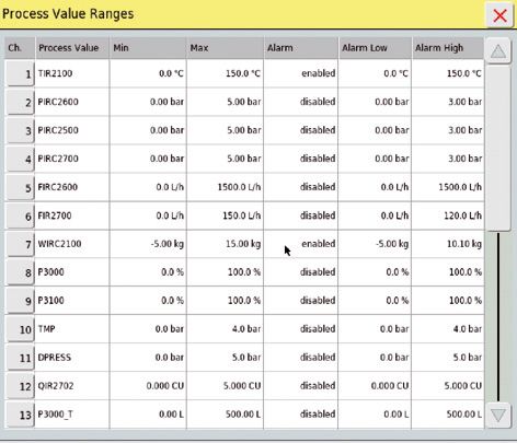
Settings of the process values (e. g. min., max., alarm values etc.)
By pressing the button „process values“ the display in the main window changes
to the display where the values are entered.
Settings of the process values (e.g. min., max., alarm values etc.)
30 Operation of the Filtration SystemSettings of external connections (not available)
Configuration of all analog and digital entries and exits as well as control cycles.
By pressing the button „manual operation“ the display in the main window
changes to the display where the values are entered and all process values as well as
in- and outputs are indicated.
Manual operation of all analog and digital entries and exits as well as control cycles.
By pressing the button „Users“ the display in the main window changes to the display
where all existing users are listed and new users can be integrated.
Operation of the Filtration System 31User settings.
Edit User.
Log Book.
32 Operation of the Filtration SystemLog Book with process messages.
Changes and operations are recorded with time and user.
Service menu
This menue can only be operated by Sartorius Service.
Operation of the Filtration System 33Alarm
By pressing the „Alarm“ button the display in the main window changes to the
display of alarms. Here all alarms which have occurred during the running process
are displayed.
Status „Ready for operation“ Status „Alarm“
1 2 3 4 5
6
Figure 3-6: Alarm display of the SARTOFLOW® Alpha plus SU
1. Alarm time (time of the arising alarm).
2. Alarm text (description of the alarm).
3. Alarm status (unreceipted | receipted).
4. Button to receipt an alarm (single receipt).
5. Button to cancel an alarm (receipt and cancel).
6. Button for the actualization of the alarm display.
34 Operation of the Filtration SystemRemote mode
The remote mode is deactivated. There is a communication between the external
control and the DCU4 control unit. The remote control is deactivated. The operator
cannot access the DCU4 control unit from an external control (e. g. MFCS/win).
Data transfer to an external control will not be interrupted.
The remote mode is activated. There is a communication between the external
control and the DCU4 control unit. The bi-directional control is activated. A remote
control of the DCU4 control unit is possible.
If you use MFCS/win or MFCS/DA the remote mode should be activated, in order
to set the DCU4 control unit in the bi-directional status. Only that way it is
guaranteed that the remote control of the DCU4 control unit works correctly.
Phases
Before starting a process you should tare the pressure sensors and the load cell.
The flow meters have to be calibrated by entering the k factor in the
calibration window.
General
The system provides the following phases and controller:
1. Tare Pressure 4. Concentration 7. DPRESS
2. Tare Wight 5. Diafiltration
3. Conditioning 6. TMP
Operation of the Filtration System 35The phases will be started from the operator panel and the DCU executes the steps
with interaction of the operator. A phase can be started and stopped at each
state by the operator. If no phase is active, the system is in manual mode. In this
mode the feed pump can be started and all valves can be operated directly from the
operator panel.
1. Phase „TARE PRESSURE“ The sequence “PRESSURE” is used to set all the pressure sensors to zero automatically
before using another phase. It has to be started after a new bag assembly is
installed. This phase should only be started with an empty bag immediately after the
installation. The sequence executes the steps automatically, also triggers “operator
information | messages or questions” and waits for operator interaction wherever it is
necessary as described below: This phase starts after activating the start button in
the phase menu and confirming by pressing OK.
2. Phase „TARE WEIGHT“ The sequence “WEIGHT” is used to set the load cell to zero automatically before using
another phase. The sequence executes the steps automatically, also triggers “operator
information | messages or questions” and waits for operator interaction wherever
it is necessary as described below: This phase starts after activating the start button in
the phase menu and confirming by pressing OK.
36 Operation of the Filtration System3. Phase „CONDITIONING“ The phase “Conditioning” is used to flush the cassettes with buffer and prepare them
for the process. The peristaltic pumps fill the recirculation bag with buffer until the
filling volume reaches the defined end level. The buffer flushes the filter cassettes and
is collected in a waste container. The sequence executes the steps automatically, also
triggers “operator information | messages or questions” and waits for operator inter-
action wherever it is necessary. This phase starts after activating the start button in
the phase menu and confirming by pressing OK. The phase should only be used for the
flushing new bag assemblies after the installation.
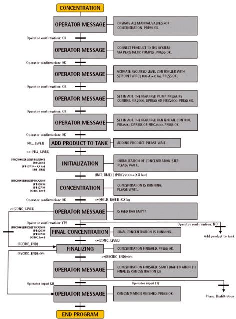
Operation of the Filtration System 374. Phase „CONCENTRATION“ The phase “Concentration” is used to concentrate the working volume until the level
drops down to a defined end level. The sequence executes the steps automatically,
also triggers “operator information | messages or questions” and waits for operator
interaction wherever it is necessary. This phase starts after activating the start button
in the phase menu and confirming by pressing OK.
38 Operation of the Filtration System5. Phase „DIAFILTRATION“ The sequence “Diafiltration” substitutes media for buffer. During the concentration
phase the working volume decreases to a defined level. Once the hold level is reached
the peristaltic pump will adjust the weight to the defined level. If the level sensor reg-
isters a weight that is 0,1 kg below the defined level, the peristaltic pump stops and
the DCU submits a query to the operator and asks for more buffer. When the buffer
supply can be guarantied, the operator has to confirm the status and the
system fills up the tank until the set point is reached and continues with the diafiltra-
tion step. The sequence executes the steps automatically, also triggers “operator
information | messages or questions” and waits for operator interaction wherever it
is necessary as described below: This phase starts after activating the start button in
the phase menu and confirming by pressing OK.
Operation of the Filtration System 396. „TMP CONTROL“ The sequence “TMP Control” is used to control the transmembrane pressure by using
the “difference pressure control loop” and the “TMP control loop”. The sequence
executes the steps automatically, also triggers “operator information | messages or
questions” and waits for operator interaction wherever it is necessary as described
below: This phase starts after setting the TMP controller into “manual” or
“automatic” mode.
7. „DPRESS CONTROL“ The sequence “DPRESS” is used to control the differential pressure by using the
“DPRESS control loop”. The sequence executes the steps automatically, also triggers
“operator information | messages or questions” and waits for operator interaction
wherever it is necessary as described below: This phase starts after setting the
DPRESS controller into “manual” or “automatic” mode.
For your notices:
40 Operation of the Filtration System4. Appendix 4. Appendix
4.1 Technical Data Dimensions 1300 + 1200 + 960 mm
Weight Approx. 150 kg
Power supply 110 Volt AC or 230 Volt AC (16 A)
Pressure –1 to +3 bar
Filter area 0.1 m² to 0.3 m²
Weighing range 0 to 100 kg
Pump capacity 300 L/h at 3 bar
Material Stainless steel
Communication connection Ethernet
4.2 Cleaning and Care The cleaning and maintenance intervals mainly depend on the degree of wear and
pollution of the accessories.
You can clean the machine surfaces with common household dish liquids or alcohol.
For the care of stainless steel surfaces the respective stainless steel cleaning agents
of leading manufacturers are suited.
Please avoid aggressive cleaning agents, e.g. chloric cleaning agents
4.3 Maintenance and Service The maintenance of the SARTOFLOW® Alpha plus SU is restricted to the general test
and inspection works of the filtration module.
t See chapter 2.4.3 „Inspection of the Filtration Unit“
In the case of other malfunctions of the unit please contact your responsible service
of Sartorius Stedim Systems GmbH.
t See chapter 4.10 „Contact – Addresses“
Appendix 414.4 Causes of Malfunction
Malfunction Possible reasons Possible countermeasures
Display rests dark Unit has not been switched on Check power supply | start the unit again
Incorrect system start Start the system again
Emergency stop is activated Deactivate emergency stop
Unit cannot be started Wrong power supply Check power supply
Emergency stop is activated Deactivate emergency stop
Pump P-2500 does not start Pump cover is not closed Close the pump cover
Flexible-tube pump P-3000 does Incorrect controller settings Check controller settings
not start
Sequence cannot be started Other sequence is active Check active sequences and eventually
deactivate them
Alarms are active Receipt alarms
Measured values are wrong or Connection error between measuring Check cable connections
they are not displayed device and DCU4 control unit
No communication between DCU4 Remote button has not been activated Check remote settings
control unit and MFCS
Ethernet cable has not been Connect Ethernet cable correctly
connected correctly
Measured values indicate the maximum Cable break Check cable connections
measured value
Measurement range has been exceeded Check measurement range
Wrong results at pressure measurement Measuring instrument not calibrated Calibrate measuring device
No zero point alignment Carry out zero point alignment
Wrong results at level measuring Weighing machine not tared Tare weighing machine
Measuring instrument not calibrated Calibrate measuring instrument
Wrong results at flow measuring The calibration factor k has not been Adjust the calibration factor k
given correctly to the installed turbine
42 Appendix4.5 Disassembly and Disposal
Disassembly
t „Fill out the declaration of decontamination (chapter 4.8)“
Pay attention to the qualification of the disassembling personnel.
– Only instructed | skilled personnel (experts) must demount the filtration system.
– Only qualified personnel must be in charge with specific areas (hydraulic systems,
gas, electro technology etc.).
Conditions for the disassembly.
– The filtration system must be completely emptied before disassembling it.
– Strong pollutions must be removed. You must clean the components polluted
by dangerous substances (before disassembling).
– Set the main switch to „0“and save this position.
– Lock the energy supply and save it.
– Separate the DCU4 tower from the power supply unit.
Unload the containers and lines (under pressure).
– Unload the containers and lines under pressure at the specified locations.
– Close the connections after having disconnected the lines.
Springs and similar components (under tension) must be unloaded.
– Unload the tightened springs.
Carry out the disassembly.
– Arrange the disassembled filtration unit components so that they are suited
for the transport.
Disposal
Collect dangerous substances.
– Operating materials may contain dangerous substances. Clean the components
which have been polluted by dangerous substances (before the disassembly).
– Collect all operating materials and other harmful substances in collecting tanks
and dispose them according to the statutory provisions (professional disposal).
Please observe the statutory provisions.
– The disposal of the filtration system must be carried out according to the
applicable laws and regulations.
– Since the filtration system is fixed in the operating state, the old electronics
guideline „WEEE“ is not applicable.
– You must eventually sign off the filtration unit or any parts must | can be returned
to the manufacturer.
– Before the dispatch you must identify the parts which have been polluted by
dangerous substances.
You have to care for a separate disposal of the different components according
to the type of material.
– Metal and non-ferrous metals at metal recycling companies.
– Plastics and compounds at plastic recycling companies.
Appendix 434.6 Warranty As far as not stipulated otherwise all products of Sartorius Stedim Systems GmbH
are subject to a warranty according to the valid general terms of business.
– All components of SARTOFLOW® Alpha plus SU have been designed for the use in
common filtration processes. Under special environmental ambient conditions or
when using aggressive media you must check the suitability and durability of all
components.
– The warranty applies for all construction, fabrication or material faults and the
resulting malfunctions. It includes the repair or the replacement of damaged parts.
– The warranty does not refer to consumables and parts which are subject to wear
and tear (for example electrodes, o-rings, seals, membrane filters). Excluded from
the guarantee are also any malfunctions, defects or resulting damages due to
corrosion at improper ambient conditions or at the use of corroding materials.
Warranty and liability claims are excluded at those components,
– which do not correspond with the specifications for the unit and its application.
– which are procured from other suppliers.
– for which Sartorius Stedim Systems has not given its written authorization of use.
4.7 EC Declaration of Conformity EC declaration of conformity see enclosure
4.8 Declaration of Decontamination Declaration of decontamination see enclosure
4.9 Contact Addresses Contact addresses see enclosure
44 Appendix4.10 Information and Attention must be paid to the applicable laws, rules and regulations, when disposing
Instructions on Disposal of the contaminated components.
The packaging is to be taken to a local waste disposal site if no longer required.
The packaging is made of environmentally friendly materials that can be used as
secondary raw materials.
The equipment, including accessories and batteries, does not belong in your regular
household waste. EU legislation requires its Member States to collect electrical and
electronic equipment and disposed of it separately from other unsorted municipal
waste with the aim of recycling it.
In Germany and several other countries, Sartorius Stedim Biotech GmbH itself
assumes responsibility for the return and conformant disposal of its electronic and
electrical products. These products may not be placed with household waste or
brought to collection centers run by local public disposal operations – not even by
small commercial operators.
For disposal in Germany and in the other member nations of the European Economic
Area (EEA), please contact our local service technicians or our Service Center in
Goettingen, Germany:
Sartorius Stedim Biotech GmbH
Servicezentrum Biotechnologie
August-Spindler-Strasse 11
37079 Goettingen, Germany
WEEE-Reg.-No. DE 89907997
In countries that are not members of the European Economic Area (EEA) or where no
Sartorius Stedim Biotech subsidiaries or dealerships are located, please contact your
local authorities or a commercial disposal operator.
Prior to disposal and |or scrapping of the equipment, any batteries should be removed
and disposed of in local collection boxes.
Sartorius Stedim Biotech will not take back equipment contaminated with hazardous
materials (ABC contamination) – either for repair or disposal. Please refer to the
package leaflet | the included CD ROM or to our web site (www.sartorius-stedim.com)
for more detailed information and addresses for repair service or disposal of
your device.
Appendix 4546
Inhalt
1. Aufbau und Einsatz . . . . . . . . . . . . . . . . . . . . . . . . . . . . . .52    3. Betrieb des Filtrationssystems . . . . . . . . . . . . . . . . . . . . .65
   1.1   Allgemeine Hinweise . . . . . . . . . . . . . . . . . . . . . . . .52            3.1    Starten der Einheit | Notabschaltung . . . . . . . . . . 65
   1.2   Aufbau des Systems . . . . . . . . . . . . . . . . . . . . . . . .52             3.2    Display . . . . . . . . . . . . . . . . . . . . . . . . . . . . . . . . . . . 65
                                                                                          3.2.1 Touchfelder auf der Startanzeige . . . . . . . . . . . . . 65
2. Aufstellung und Inbetriebnahme . . . . . . . . . . . . . . . . . .54                   3.3    Betriebsarten . . . . . . . . . . . . . . . . . . . . . . . . . . . . . . 66
   2.1   Allgemeine Informationen . . . . . . . . . . . . . . . . . . . 54                3.3.1 Manueller Betrieb . . . . . . . . . . . . . . . . . . . . . . . . . . 66
   2.1.1 Aufstellfläche . . . . . . . . . . . . . . . . . . . . . . . . . . . . . 54      3.3.2 Semi-automatischer Betrieb . . . . . . . . . . . . . . . . . 66
   2.1.2 Vorbereitung des Arbeitsplatzes . . . . . . . . . . . . . . 55                   3.3.3 Menüleiste . . . . . . . . . . . . . . . . . . . . . . . . . . . . . . . . 66
   2.2   Allgemeine Abschlüsse und
                                                                                       4. Anhang . . . . . . . . . . . . . . . . . . . . . . . . . . . . . . . . . . . . . . . . .83
         Installationsmaterial der Filtrationseinheit . . . . . 55
                                                                                          4.1  Technische Daten . . . . . . . . . . . . . . . . . . . . . . . . . . 83
   2.2.1 Hauptanschlüsse . . . . . . . . . . . . . . . . . . . . . . . . . . . 55
                                                                                          4.2  Reinigung und Pflege . . . . . . . . . . . . . . . . . . . . . . . 83
   2.2.2 Kommunikation (Ethernet) . . . . . . . . . . . . . . . . . . 55
                                                                                          4.3  Instandhaltung und Wartung . . . . . . . . . . . . . . . . 83
   2.2.3 Abwassereinleitung . . . . . . . . . . . . . . . . . . . . . . . . 55
                                                                                          4.4  Ursachen von Störungen . . . . . . . . . . . . . . . . . . . . 84
   2.2.4 Abluft | Belüftung . . . . . . . . . . . . . . . . . . . . . . . . . . 55
                                                                                          4.5  Demontage und Entsorgung . . . . . . . . . . . . . . . . . 85
   2.3   DCU4 Tower . . . . . . . . . . . . . . . . . . . . . . . . . . . . . . . 56
                                                                                          4.6  Gewährleistung . . . . . . . . . . . . . . . . . . . . . . . . . . . . 86
   2.3.1 Aufbau des DCU4 Towers . . . . . . . . . . . . . . . . . . . . 56
                                                                                          4.7  EG-Konformitätserklärung . . . . . . . . . . . . . . . . . . 86
   2.3.2 Aufstellung und Ausrichtung des DCU4-Towers . 56
                                                                                          4.8  Dekontaminierungserklärung . . . . . . . . . . . . . . . . 86
   2.3.3 Signal- und Stromeinspeisung des DCU4-Towers 57
                                                                                          4.9  Kontaktadressen . . . . . . . . . . . . . . . . . . . . . . . . . . . 86
   2.4   Filtrationseinheit . . . . . . . . . . . . . . . . . . . . . . . . . . 57
                                                                                          4.10 Informationen und Anweisungen
   2.4.1 Aufbau des Filtrationssystems . . . . . . . . . . . . . . . . 57
                                                                                               zur Entsorgung . . . . . . . . . . . . . . . . . . . . . . . . . . . . 87
   2.4.2 Aufstellung und Ausrichtung
         der Filtrationseinheit . . . . . . . . . . . . . . . . . . . . . . . 58
   2.4.3 Überprüfung der Filtrationseinheit . . . . . . . . . . . . 58
   2.4.4 Signal- und Stromeinspeisung
         der Filtrationseinheit . . . . . . . . . . . . . . . . . . . . . . . 59
   2.4.5 Befestigung des Rezirkulationsbehälters
         (Beutel als Rezirkulationsbehälter) . . . . . . . . . . . . 59
   2.4.6 Montage des vorsterilisierten
         Crossflow Bag Loops . . . . . . . . . . . . . . . . . . . . . . . 60

                                                                                                                                                                Inhalt           47
Einleitung Einleitung
In dieser Bedienungsanleitung werden die Installation und Inbetriebnahme, der
Anschluss der Energie-|Stromversorgungsmodule sowie die Bedienung eines
SARTOFLOW®-Filtrationssystem beschrieben.
Informationen zu den verschiedenen Komponenten finden Sie in den externen
Bedienungsanleitungen.
Einsatz des Das SARTOFLOW®-Filtrationssystem ist für die kontinuierliche Filtrierung von
SARTOFLOW®-Filtrationssystems Suspensionen und flüssigen Medien im Labor und in der Produktion geeignet.
Da das Filtrationssystem auf die Verwendung mit verschiedenen Arten von
eigenständigen Einheiten ausgelegt ist, kann es sowohl für die Mikrofiltration
als auch für die Ultrafiltration eingesetzt werden.
Bei speziellen Prozessen ist die Verwendung möglicherweise nur unter bestimmten
Umständen zulässig. In Bezug auf die biologische Sicherheit sind z. B. spezielle Anfor-
derungen an den Arbeitsplatz, die Instrumentierung, die Handhabung der
Komponenten, die Sicherheit der Mitarbeiter und die Arbeitsumgebung zu beachten.
Auf diese Anforderungen sowie andere Bestimmungen, die gesetzlich oder anderweitig
vorgeschrieben sind, wird in dieser Bedienungsanleitung nicht eingegangen.
Für die Bedienung des Filtrationssystems werden die Kenntnisse eines Experten im
Umgang mit Mikroorganismen, Zellen und kontaminierten Objekten vorausgesetzt. Sofern
für die Anwender und die Arbeitsumgebung bei der Handhabung von Komponenten spe-
zielle Risiken bestehen, enthält die Bedienungsanleitung Gefahren-, Warn-, Vorsichts- und
Sicherheitshinweise. Sie gelten zusätzlich zu den Bestimmungen zur Verwendung am
Arbeitsplatz.
Das SARTOFLOW®-Filtrationssystem wurde nur für den stationären Betrieb entwickelt.
Zeichen und Symbole Gefahrenhinweise sind mit dem vorstehenden roten Symbol gekennzeichnet.
!
Bei Nichtbeachtung der Gefahrenhinweise besteht ein großes Risiko, dass es zu
Geräte- bzw. anderen Materialschäden oder Personenschäden kommt.
Warnhinweise sind mit dem vorstehenden orangefarbenen Symbol gekennzeichnet.
Bei Nichtbeachtung der Warnhinweise besteht ein mittleres Risiko, dass es zu
Geräte- bzw. anderen Materialschäden oder Personenschäden kommt.
Vorsichtshinweise sind mit dem vorstehenden gelben Symbol gekennzeichnet.
Bei Nichtbeachtung der Vorsichtshinweise besteht ein geringes Risiko, dass es zu
Geräte- bzw. anderen Materialschäden oder Personenschäden kommt.
Sicherheitshinweise und allgemeine Hinweise sind mit dem vorstehenden Symbol
gekennzeichnet.
Die unter diesem Symbol aufgeführten Schritte sind mit größter Sorgfalt auszu-
führen.
Es erscheint immer dann, wenn besondere Aspekte zu berücksichtigen sind.
t Unter diesem Zeichen wird Bezug auf Informationen in diesem Dokument oder
anderen Dokumenten genommen. In den Klammern befinden sich Quellangaben
zu Abbildungen, Absätzen oder Dokumenten.
§ Die mit diesem Zeichen gekennzeichneten Absätze enthalten Bedienungsschritte,
die nacheinander auszuführen sind.
48 EinleitungEinleitung Das SARTOFLOW®-System für die Mikrofiltration oder Ultrafiltration gehört zum
Produktprogramm von Sartorius Stedim.
Bei Fragen zu diesem System oder anderen Geräten aus dem Produktprogramm
von Sartorius Stedim können Sie uns unter folgender Adresse kontaktieren.
Sartorius Stedim Systems GmbH
Robert-Bosch-Str. 5–7
34302 Guxhagen, Deutschland
Telefon: +49.5665.407.0
Fax: +49.5665.407.2201
Hinweise zu dieser Dokumentation Alle Informationen zum SARTOFLOW®-Filtrationssystem entsprechen dem Wissens-
stand zum Zeitpunkt der Veröffentlichung des vorliegenden Dokuments. Wir behalten
uns das Recht vor, die verschiedenen Komponenten des Filtrationssystems gegenüber
den Informationen und Änderungen in diesem Dokument ohne gesonderte Ankündi-
gung zu ändern. Dritten ist es nicht gestattet, die Bedienungsanleitung ohne vorheri-
ge schriftliche Genehmigung zu ändern. Dasselbe gilt in Bezug auf das Kopieren oder
die Verwendung des Dokuments zu anderen Zwecken.
Einleitung 49Sie können auch lesen