4032 Betriebsanleitung Manuel d'utilisation - Operating Instructions - Schubert & Salzer
←
→
Transkription von Seiteninhalten
Wenn Ihr Browser die Seite nicht korrekt rendert, bitte, lesen Sie den Inhalt der Seite unten
Betriebsanleitung

                    Operating Instructions

                    Manuel d'utilisation

                            4032

Version: 02/2021
                        Bunsenstrasse             D-85053 Ingolstadt
M4032def.doc            Tel: (0841) 9654-0        Fax: (0841) 9654-590
Art.-Nr: 110 4032       www.schubert-salzer.com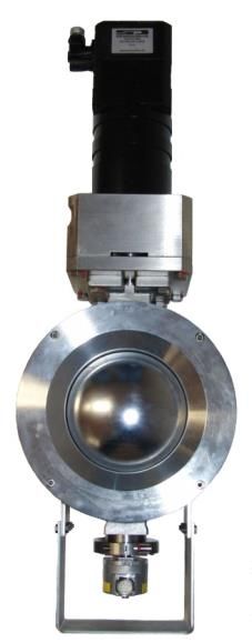
Inhalt/Content/Sommaire

1          Betriebsanleitung (deutsch) ...................................................... 3

    1.1   Allgemeines                                                                       3
    1.2   Technische Daten                                                                  3
    1.3   Elektrische Anschlüsse                                                            4
    1.4   Anschluss der Antriebseinheit                                                     7
    1.5   Handverstellung                                                                   7
    1.6   Konfigurierung                                                                    8
    1.7   Wartung                                                                           15
    1.8   Abmessungen                                                                       18
    1.9   Explosionsschutz nach ATEX 2014/34/EU                                             20

2                 Operating Instructions (English) ..................................... 22

    2.1   General                                                                           22
    2.2   Technical data                                                                    22
    2.3   Electrical connections                                                            23
    2.4   Actuation unit connection                                                         26
    2.5   Manual positioning                                                                26
    2.6   Configuration                                                                     27
    2.7   Maintenance                                                                       34
    2.8   Dimensions                                                                        37
    2.9   Explosion protection according to ATEX 2014/34/EU                                 39

3           Instructions de service (français) ........................................... 41

    3.1   Généralités                                                                       41
    3.2   Caractéristiques techniques                                                       41
    3.3   Raccords électriques                                                              42
    3.4   Raccordement de l’actionneur                                                      45
    3.5   Actionnement manuel                                                               45
    3.6   Configuration                                                                     46
    3.7   Maintenance                                                                       53
    3.8   Dimensions                                                                        56
    3.9   Protection antidéflagrante selon ATEX 2014/34/UE                                  58

                                                  –2–
1               Betriebsanleitung (deutsch)

1.1 Allgemeines
Der Stellantrieb wird zusammen mit Kugelsektorventilen DN80 bis DN250 ausgeliefert.
Der Stellantrieb wird nach Kundenwunsch werksseitig zur Kommandierung über ein analoges
Stellsignal (4-20mA), über Schritt-/Richtungssteuerung oder über PROFIBUS-DP konfiguriert.
Jedwede Bewegung des Stellantriebs erfolgt positionsgeregelt. Eine externe Positionsregelung
ist nicht erforderlich.
Die Installation und die Inbetriebnahme müssen durch entsprechend qualifiziertes und
geschultes Personal erfolgen.
Die Positionsmessung erfolgt hochgenau abtriebsseitig und kräftefrei.

1.2 Technische Daten
Technische Daten Ventil
Bauform                    Zwischenflansch-Ausführung
Nennweiten                 DN 80 bis DN 250
                           Bis PN 25 nach DIN 2401, je nach Nennweite
Nenndruck
                           für Flansche PN 10 – PN 40
Medientemperatur           O-Ringe VITON           -10°C bis +170°C
                           Weitere Angaben siehe „Dichtungswerkstoffe“

Umgebungstemperatur        -10°C bis +60°C
Leckrate mit PTFE-Sitz     Leckrate 2 nach DIN 3230-BO
          mit Metallsitz   < 0,01% vom Kvs-Wert

Technische Daten Antrieb
                                                                            Ansteuerung
Ausführung                               Analog                Schritt-/Richtung             PROFIBUS-DP              CAN-Bus
Stellsignal                            4 … 20 mA               24V, 400Hz, max.              PROFIBUS-DP              CAN-Bus
Positionsregelung                                        Intern, keine externe Positionsregelung erforderlich!
Bürde                                     470 Ω                       1500 Ω                         -                     -
Pulsbreite                                   -                  50%, 1 ms min.                       -                     -
Hilfsenergie, elektrisch                                     100 … 230 VAC [±10%], 50 … 60 Hz [±10%]
Antriebsart                                                       Servomotor mit Planetengetriebe
Stellgenauigkeit                   8192 Schritte / 90°         8192 Schritte / 90°        8192 Schritte / 90°     8192 Schritte / 90°
Drehwinkelerfassung                                                15 Bit absolut Drehwinkelgeber
Stellbereich                                                                    0 … 90°
Stellgeschwindigkeit                ca. 2s bis 5 min.             max. 400 Hz                ca. 2s bis 5 min.     ca. 2s bis 5 min.
Positionsrückmeldung             4 … 20 mA, Bürde: 1kΩ max., Auflösung: 10 Bit                           Über Bussystem
Anpassung                                                                      werksseitig
Konfiguration                                                    Per PC-Software ValveConfig4032
Zul. Umgebungsbedingungen                          Am Antrieb: -10°C bis +60°C, rel. Feuchte:
1.3 Elektrische Anschlüsse
Der elektrische Anschluss darf nur durch qualifiziertes Personal erfolgen.
Beachten Sie unbedingt bei Montage, Inbetriebnahme und Betrieb der Geräte die
entsprechenden nationalen Sicherheitsvorschriften (z. B. VDE 0100).
Alle Arbeiten dürfen nur im spannungslosen Zustand erfolgen.
Das Nichtbeachten der entsprechenden Vorschriften kann zu schweren Verletzungen
sowie zur Beschädigung des Antriebs, des Ventils oder anderer Teile der Anlage
führen.
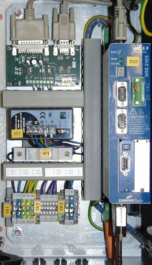
A Spannungsversorgung
B Erdungsklemmen
C Analoge Positionsrückmeldung
D Klemmen für Sollwertvorgabe
E Anschluss für PROFIBUS-DP
E
B D
A C
Für den elektrischen Anschluss der Stellsignalleitung wird ein geschirmtes Kabel empfohlen.
Die zusätzlich erforderliche Spannungsversorgung muss dabei über ein getrenntes zweites
Kabel erfolgen.
–4–Nach dem Öffnen der Tür des Schaltschranks sind die Schraubklemmen der Klemmleiste für
die einzelnen Anschlüsse zugänglich.
Die Spannungsversorgung wird an 1X1 angeschlossen (Marke A im Bild oben, Erdung an
Marke B).
Für alle externen Leitungen werden paarweise verdrillte Leitungen (Twisted-Pair) mit Schirm
empfohlen. Der Schirm ist auf beiden Seiten mit dem Gehäuse zu verbinden.
Die Spannungsversorgung ist bauseits mit einer Sicherung B16A und einem allstromsensitiven
FI-Schutzschalter (300mA) abzusichern.
Nicht verwendete Kabelverschraubungen sind unbedingt mit einem geeigneten
Verschlussstopfen abzudichten um die Schutzart (IP65) zu erhalten.
1.3.1 Ausführung für analoge Sollwertvorgabe
Als Stellsignal ist ein Stromsignal von 4-20mA anzulegen. Das Stellsignal wird an der
Klemmleiste (1X2) an den Klemmen 3 (AIN+) und 4 (AIN-) (Marke D im Bild oben)
angeschlossen. Die Positionierung erfolgt dabei absolut.
Die analoge Rückmeldung der Position erfolgt über ein Stromsignal von 4-20mA
(Auflösung: 10bit) und wird an der Klemmleiste (1X2) an den Klemmen 1 (FB+) und 2 (FB-)
(Marke C im Bild oben) angeschlossen.
Um eine ausreichende Verträglichkeit gegenüber elektromagnetischen Störungen
sicherzustellen, muss der Stellungsregler geerdet werden. Im Schaltschrank befinden
sich entsprechend markierte Erdungsklemmen und Erdungsschrauben.
Der Minuspol des Stellsignaleingangs ist mit dem GND der Betriebsspannung
verbunden. Beachten Sie bitte dabei, ob die Spannungsquellen in Ihrem System
geerdet werden dürfen, ansonsten ist für den Stellungsregler eine eigene Versorgung
vorzusehen!
1.3.2 Ausführung für Schritt-/Richtungssteuerung
Das Stellsignal wird digital mittels Richtung und Schrittzahl vorgegeben. Die Signaleingänge
sind galvanisch getrennt und für einen Signalhub von 24V ausgelegt. Die maximale
Eingangsfrequenz beträgt 400 Hz. Die Pulsbreite soll 50% mit einer Mindestpulsdauer von 1ms
sein.
Das Schrittsignal wird an der Klemmleiste (1X2) an den Klemmen 3 (CLK) und 4 (GND) (Marke
D im Bild oben) angelegt.
Das Richtungssignal wird an der Klemmleiste (1X2) an den Klemmen 5 (DIR) und 6 (GND)
(Marke D im Bild oben) angeschlossen.
Die analoge Rückmeldung der Position erfolgt über ein Stromsignal von 4-20mA
(Auflösung: 10bit) und wird an der Klemmleiste (1X2) an den Klemmen 1 (FB+) und 2 (FB-)
(Marke C im Bild oben) angeschlossen.
–5–Eine zu hohe Spannung oder eine zu hohe Eingangsfrequenz können das Gerät
beschädigen.
Um eine ausreichende Verträglichkeit gegenüber elektromagnetischen Störungen
sicherzustellen, muss der Stellungsregler geerdet werden. Im Schaltschrank befinden
sich entsprechend markierte Erdungsklemmen und Erdungsschrauben.
1.3.3 Ausführung für CAN-Bus
Die Bedienung des Stellantriebs per CAN-Bus ist möglich. Wenden Sie sich hierzu bitte an
Ihren Vertriebspartner.
1.3.4 Ausführung für PROFIBUS-DP
Der PROFIBUS-Bus-Anschluss ist gemäß EN 50170 als 9-polige DSUB-Buchse auf der
Oberseite des Servoreglers (blau) ausgeführt.
Pin Signal Beschreibung Beschreibung
Kabel Slave
1 Schirmung Schirmung / Potentialausgleich
2 n. c. n. c.
3 RxD/TxD-P Daten senden / empfangen; Datenader A
4 CNTR-P n. c. Repeater Steuersignal
5 DGND Masse für Datensignale und 5V
6 VP / +5V +5V Spannungsversorgung (max. ca. 30mA)
7 n. c. n. c.
8 RxD/TxD-N Daten senden / empfangen; Datenader A
9 CNTR-N n. c. Repeater Steuersignal
Es wird ein Kabel von SIEMENS, Bestell-Nr.: 6XV1 830-0EN20: SIMATIC NET, PB FC
Standard Busleitung, 2-adrig und geschirmt, Spezialaufbau für Schnellmontage, 20 m,
empfohlen.
Jedes Bussegment eines PROFIBUS-Netzwerkes ist mit Busabschlusswiderständen zu
versehen, um Leitungsreflexionen zu minimieren, ein nahezu konstantes Lastverhalten am Bus
zu gewährleisten und ein definiertes Ruhepotential auf der Leitung einzustellen. Die
Terminierung erfolgt jeweils am Anfang und am Ende eines Bussegments.
Der Servoregler hat diese Abschlusswiderstände integriert, so dass keine externe Beschaltung
(spezieller Stecker) notwendig ist. Diese können über die zwei DIP-Schalter auf dem Modul
zugeschaltet werden (Schalter auf ON).
–6–Eine externe Beschaltung ist ebenfalls möglich. Die für die extern beschalteten
Abschlusswiderstände benötigte Versorgungsspannung von 5 V wird am PROFIBUS-Anschluss
des Servoreglers (siehe Steckerbelegung) zur Verfügung gestellt.
Ist die eingestellte Baudrate > 1,5 MBaud müssen aufgrund der kapazitiven Last des
Teilnehmers und der somit erzeugten Leitungsreflexion Stecker mit integrierten
Längsinduktivitäten (110 nH) verwendet werden. Einige Hersteller bieten Anschlussstecker an,
die eine Kombination der Busabschlusswiderstände und Längsinduktivitäten enthalten.
1.4 Anschluss der Antriebseinheit
Der Schaltschrank wird mit drei Kabeln (2x orange, 1x schwarz) mit der Antriebseinheit
verbunden.
Positionsgeber Ventil Motor
Die Kabel sind beschriftet und werden entsprechend der Beschriftung angeschlossen.
Die beiden orangen Kabel (Beschriftung: Pow und Res) werden an die entsprechend markierten
Gegenstecker am Motor angesteckt.
Das schwarze Kabel (Beschriftung: Enc) wird an den entsprechend markierten Gegenstecker
am Positionsgeber angesteckt.
1.5 Handverstellung
Im Falle einer Fehlfunktion der übergeordneten Steuerung kann das Ventil von Hand verstellt
werden. Im unwahrscheinlichen Fall eines kompletten Ausfalls des Systems oder der
Versorgungsspannung kann das Ventil ebenfalls von Hand bedient werden.
Die Handnotverstellung kann nur dann angewendet werden, wenn der Regler „inaktiv“ also
stromlos ist. Dazu muss der Hauptschalter an der Vorderseite des Schaltschranks auf „OFF“
gestellt sein.
Ein Bedienen der Notverstellung im eingeschalteten Zustand ist nicht möglich!
Hauptschalter auf „OFF“ stellen!
Der Versuch kann zu schweren Verletzungen sowie zur Beschädigung des
Antriebs, des Ventils oder anderer Teile der Anlage führen.
Ist der Antrieb deaktiviert, kann der beiliegende Hakenschlüssel (24) in die Öffnung (22) der
Antriebseinheit (21) gesteckt werden. Der Haken des Schlüssels greift in die Nuten der Welle.
Bei stehend montiertem Antrieb schließt eine Drehung nach links das Ventil (23). Nach dem
Verstellen des Ventils ist der Schlüssel wieder zu entfernen.
Es ist zu beachten, dass es im System keine mechanischen Endanschläge gibt. Wird der
Antrieb über den Schließpunkt hinaus gedreht, so kann dies zu einer Beschädigung des Ventils
führen.
–7–21 Antriebseinheit
22 Öffnung für Notverstellung
23 Ventil
24 Schlüssel für Notverstellung
21 22 24 23
Nach Bedienen der Notverstellung den Schlüssel wieder entfernen!
Niemals den Schlüssel im Gerät belassen. Dies kann zu schweren Verletzungen
sowie zur Beschädigung des Antriebs, des Ventils oder anderer Teiler der Anlage
führen.
Der Stellantrieb beinhaltet keine mechanischen Endanschläge. Zu weites Drehen
kann das Ventil beschädigen.
Die Handverstellung ist eine Notfallbetriebsart und ist nicht für den regelmäßigen Betrieb
vorgesehen.
1.6 Konfigurierung
1.6.1 Referenzierung
Die Referenzierung des montierten Stellungsreglers wurde im Werk vorgenommen.
Sie ist normalerweise nur nach einem Austausch oder nach einer Reparatur des
Ventils oder des Antriebs erforderlich.
Bevor ein Stellantrieb, der demontiert wurde, wieder in Betrieb genommen werden
kann, muss eine Referenzierung durchgeführt werden.
Wird keine Referenzierung durchgeführt, kann dies zu schweren Verletzungen
sowie zur Beschädigung des Antriebs, des Ventils oder anderer Teile der Anlage
führen.
Die Referenzierung ist von einem entsprechend geschulten Servicetechniker mittels der dafür
vorgesehenen Software ValveConfig4032 durchzuführen. Das Vorgehen bei der
Referenzierung ist zusammen mit den weiteren Softwarefunktionen in einem separaten
Softwarehandbuch beschrieben.
1.6.2 Schritt-/Richtungssteuerung
Für die Schritt-/Richtungssteuerung gilt folgende Konvention:
Die Richtung wird über das Signal DIR vorgegeben.
24V entspricht Öffnen, 0V entspricht Schließen.
Schritte werden über das Signal CLK kommandiert.
Bei einer steigenden Flanke am Signal CLK wird jeweils ein Schritt ausgeführt. Die Schrittweite
kann mittels der dafür vorgesehenen Software ValveConfig4032 eingestellt werden.
–8–1.6.3 PROFIBUS-DP
1.6.3.1 Allgemeines
Über PROFIBUS-DP wird dem Stellantrieb die Sollposition, die Fahrgeschwindigkeit sowie ein
Kontrollwort kommandiert.
Zur Konfiguration der Kommunikation auf Seiten des Positionierreglers ist lediglich die Angabe
der Slave-Adresse erforderlich. Dies kann über die Software ValveConfig4032 geschehen.
Werksseitig ist die Adresse 9 eingestellt.
Der Stellantrieb unterstützt die Version DP-V0 und lehnt sich an die PROFIdrive Version 3.1 an.
Die Baudrate der PROFIBUS-Kommunikation wird von der eingesetzten Hardware automatisch
erkannt. Folgende Baudrates werden unterstützt:
Anhand der mitgelieferten GSD-Datei (MXME08CE.GSD) kann der Positionierantrieb in die Steuerung
eingebunden werden.
1.6.3.2 Zustände
Die Gerätesteuerung erfolgt durch eine Zustandsmaschine, die mit einem Kontrollwort und
einem Statuswort kontrolliert wird.
Die vereinfachte Zustandsmaschine sieht wie folgt aus:
–9–Die wichtigsten Zustandsübergänge sind dabei:
1.6.3.3 Aufbau Datentelegramme
Das Empfangsdatentelegramm ist 12 Byte lang. Der Aufbau ist in der nachfolgenden Tabelle
dargestellt.
Byte Bezeichnung PNU Wert
1 Telegrammadresse -- E0h
2 Reserviert 1002.0 FFh
3 Kontrollwort (High Byte) 967.0
4 Kontrollwort (Low Byte) 967.0
5 Sollposition [in Inkrementen] (High Byte) 1001.0
6 Sollposition [in Inkrementen] 1001.0
7 Sollposition [in Inkrementen] 1001.0
8 Sollposition [in Inkrementen] (Low Byte) 1001.0
9 Profile Velocity [in °/s] (High Byte) 1001.1 00h
10 Profile Velocity [in °/s] 1001.1 00h
11 Profile Velocity [in °/s] 1001.1
12 Profile Velocity [in °/s] (Low Byte) 1001.1
– 10 –Das Antwortdatentelegramm ist 16 Byte lang. Der Aufbau ist in der nachfolgenden Tabelle
dargestellt.
Byte Bezeichnung PNU Wert
1 Telegrammadresse -- F0h
2 Betriebsart 1500.0 10h
3 Statuswort (High Byte) 968.0
4 Statuswort (Low Byte) 968.0
5 Istposition [in Inkrementen] (High Byte) 1100.0
6 Istposition [in Inkrementen] 1100.0
7 Istposition [in Inkrementen] 1100.0
8 Istposition [in Inkrementen] (Low Byte) 1100.0
9 Istgeschwindigkeit [in °/s] (High Byte) 1101.0
10 Istgeschwindigkeit [in °/s] 1101.0
11 Istgeschwindigkeit [in °/s] 1101.0
12 Istgeschwindigkeit [in °/s] (Low Byte) 1101.0
13 Wirkiststrom [in 1/1000 Nennstrom] (High Byte) 1102.0
14 Wirkiststrom [in 1/1000 Nennstrom] 1102.0
15 Wirkiststrom [in 1/1000 Nennstrom] 1102.0
16 Wirkiststrom [in 1/1000 Nennstrom] (Low Byte) 1102.0
1.6.3.4 Freigabe des Antriebs
Die Freigabe erfolgt über das Kontrollwort. Die Rückmeldung im Statuswort ist jeweils
abzuwarten.
Übergang Befehl Rückmeldung Neuer Zustand
(Kontrollwort) (Statuswort)
0000h ????h SWITCHING_ON_INHIBITED
Übergang 1 2436h 2301h READY_FOR_SWITCHING_ON
Übergang 2 2437h 2303h SWITCHED_ON
Übergang 3 243Fh 2707h OPERATION
Damit ist der Antrieb betriebsbereit und die Positionierung kann gestartet werden.
– 11 –1.6.3.5 Positionierung
Nach der Freigabe des Antriebs (siehe 1.6.3.4) kann die Positionierung gestartet werden. Die
Positionierung erfolgt über Inkremente, d.h. Schritte, symmetrisch zur Mittellage. Der gesamte
Stellbereich wird in 16384 Inkremente unterteilt. Dabei entsprechen -8192 Inkremente -45° und
0%. +8192 Inkremente entsprechen +45° und 100%. Ein Inkrement entspricht also 0,0061%
(= 0,0055°)
Die Position wird folgendermaßen berechnet:
Öffnung Winkel Inkremente Hexadezimal
0% -45° -8192 FF FF E0 00h
25% -22,5° -4096 FF FF F0 00h
50% 0° 0 00 00 00 00h
75% +22,5° +4096 00 00 10 00h
100% +45° +8192 00 00 20 00h
Umrechnung Prozent in Inkremente:
x% − 50%
8192ink = xink
50%
Umrechnung Inkremente in Prozent:
xink
50% + 50% = x %
8192ink
Umrechnung in Winkel:
x%
90 − 45 = x
100%
Die Sollgeschwindigkeit wird in Inkrementen/s angegeben.
Die Geschwindigkeitsgrenzen sind:
s ink ink
Höchste zulässige Geschwindigkeit: 10 1638,4 1638 = 666 h
90 s s
s ink ink
Geringste zulässige Geschwindigkeit: 300 54,613 55 = 37 h
90 s s
Zum Starten einer Positionierung erwartet der Antrieb eine steigende Flanke am Bit 6 des Low
Bytes des Kontrollworts. Es wird die Position angefahren, die in der Nachricht gesendet wird, in
der auch das Kontrollwort von 243Fh auf 247Fh gesetzt wird. Es wird empfohlen, das
Kontrollwort gleich wieder auf 243Fh zu setzen, damit die nächste Positionierung ohne
Verzögerungen erfolgen kann.
Die beiden folgenden Beispiele erläutern die Ansteuerung.
– 12 –Beispiel 1 zur Positionierung:
Positionieren von 0%auf 30% mit einer Geschwindigkeit von 25s/90°:
Dabei wird die Sollposition wie folgt errechnet:
x% − 50%
8192ink = xink
50%
30% − 50%
8192ink = −0,4 8192ink = −3276,8ink −3277ink = FF FF F 3 33h
50%
Die Sollgeschwindigkeit:
s 25s s ink ink
25 = = 0,001526 655.36 655 = 028Fh
90 16384ink 1ink s s
Ursprünglicher Zustand:
Byte 1 2 3 4 5 6 7 8 9 10 11 12
Wert E0h FFh 24h 3Fh FFh FFh E0h 00h 00h 00h ??h ??h
Adr. Kontroll- Soll- Soll-
wort position geschwindigkeit
Somit ist zu kommandieren:
Sollposition = -3277 = FF FF F3 33h
Sollgeschwindigkeit = 655 = 00 00 02 8Fh
Byte 1 2 3 4 5 6 7 8 9 10 11 12
Wert E0h FFh 24h 7Fh FFh FFh F3h 33h 00h 00h 02h 8Fh
Adr. Kontroll- Soll- Soll-
wort position geschwindigkeit
Anschließend wird das Kontrollwort wieder zurückgesetzt:
Byte 1 2 3 4 5 6 7 8 9 10 11 12
Wert E0h FFh 24h 3Fh FFh FFh F3h 33h 00h 00h 02h 8Fh
Adr. Kontroll- Soll- Soll-
wort position geschwindigkeit
– 13 –Beispiel 2 zur Positionierung:
Positionieren von 90% auf 70% mit einer Geschwindigkeit von 50s/90°:
Dabei wird die Sollposition wie folgt errechnet:
x% − 50%
8192ink = xink
50%
80% − 50%
8192ink = 0,6 8192ink = 4915,2ink 4915ink = 00 00 0133h
50%
Die Sollgeschwindigkeit:
s 50s s ink ink
50 = = 0,00305 327,68 328 = 00 00 0148 h
90 16384ink 1ink s s
Ursprünglicher Zustand:
Byte 1 2 3 4 5 6 7 8 9 10 11 12
Wert E0h FFh 24h 3Fh 00h 00h 19h 9Ah 00h 00h ??h ??h
Adr. Kontroll- Soll- Soll-
wort position geschwindigkeit
Somit ist zu kommandieren:
Sollposition = 4915 = 00 00 01 33h
Sollgeschwindigkeit = 328 = 00 00 01 48h
Byte 1 2 3 4 5 6 7 8 9 10 11 12
Wert E0h FFh 24h 7Fh 00h 00h 01h 33h 00h 00h 01h 48h
Adr. Kontroll- Soll- Soll-
wort position geschwindigkeit
Anschließend wird das Kontrollwort wieder zurückgesetzt:
Byte 1 2 3 4 5 6 7 8 9 10 11 12
Wert E0h FFh 24h 3Fh 00h 00h 01h 33h 00h 00h 01h 48h
Adr. Kontroll- Soll- Soll-
wort position geschwindigkeit
– 14 –1.7 Wartung
31
32
Steckverbinder für
31
Antriebseinheit
Befestigungsschrauben für
32
Antriebseinheit
Steckverbinder für
33
Winkelgeber
Befestigungsschraube für
34
Winkelgeber (DIN912 M6)
35 Klemmring
33
35
34
– 15 –1.7.1 Demontage
Referenzierung erforderlich!
Nach einer Demontage ist im Regelfall eine Referenzierung erforderlich, die nur von
einem entsprechend geschulten Servicetechniker durchgeführt werden kann.
Wird keine Referenzierung durchgeführt, kann dies zu schweren Verletzungen
sowie zur Beschädigung des Antriebs, des Ventils oder anderer Teile der Anlage
führen.
Bei Montage Anzugsdrehmomente beachten!
Zur Wartung des Ventils kann es erforderlich sein, die Antriebseinheit oder den Winkelgeber zu
demontieren. Dazu wird wie folgt vorgegangen.
1.7.1.1 Antrieb deaktivieren
Es ist sicherzustellen, dass der Antrieb deaktiviert und stromlos ist. Dazu die Stellung des
Hauptschalters überprüfen. Der Hauptschalter muss in der Stellung „OFF“ stehen.
Nach dem Abschalten des Antriebs den Stecker X1 von der Platine abziehen.
1.7.1.2 Kabel demontieren
Die beiden Stecker (31) von der Antriebseinheit abziehen.
1.7.1.3 Antriebseinheit demontieren
Die Antriebseinheit ist mit vier Schrauben (32) mit dem Ventil verbunden. Die Antriebseinheit
kann nun nach oben vom Ventil abgenommen werden.
1.7.1.4 Winkelgeber demontieren
Der Winkelgeber, der sich auf der der Antriebseinheit gegenüberliegenden Seite des Ventils
befindet, kann ebenfalls demontiert werden. Dazu wird zunächst das Kabel mit dem Stecker
(33) entfernt. Dann kann die axiale Schraube M6 gelöst und komplett herausgedreht werden.
Anschließend wird die Schraube am Spannring (35) gelöst und der Winkelgeber kann nach
unten abgezogen werden.
Schraube, Unterlegscheibe und die beiden Spannkonusse geschützt aufbewahren.
Den Winkelgeber mit dem Spannring nach unten vorsichtig auf eine ebene Fläche stellen.
Der Winkelgeber ist ein Präzisionsmessinstrument und ist entsprechend vorsichtig
zu behandeln.
– 16 –1.7.2 Montage
1.7.2.1 Winkelgeber montieren
42
43
41 Bolzen
41
42 Winkelgeber
43 Axiale Befestigungsschraube M6
44 Spannkonusse
44
Einen der beiden Spannkonusse (44) auf den Bolzen (41) stecken. Den Winkelgeber (42)
vorsichtig auf den Bolzen aufschieben. Dabei auf den korrekten des Spannkonus (44) achten.
Den zweiten Spannkonus aufsetzen. Auf das Gewinde der axialen Befestigungsschraube (43)
flüssige Gewindesicherung (z.B. Loctite 243) aufbringen, die Schraube mit Unterlegscheibe
DIN 9021 ansetzen und mit 3Nm anziehen.
Schraube des Spannrings gut handfest anziehen.
Anzugsdrehmoment beachten!
Der Winkelgeber ist ein Präzisionsmessinstrument und ist entsprechend vorsichtig
zu behandeln.
1.7.2.2 Antriebseinheit montieren
Die Antriebseinheit von oben auf das Ventil stecken. Dabei auf die korrekte Lage der Passfeder
achten.
Nach dem Aufstecken die Antriebseinheit mit vier Schrauben anschrauben. Das Gewinde der
Schrauben mit flüssiger Gewindesicherung (z.B. Loctite 243) benetzen und die Schrauben mit
einem Drehmoment von 40Nm anziehen.
1.7.2.3 Kabel anschließen
Als erstes das Winkelgeberkabel (33) anschließen; erst danach die Motorkabel (31)
anschließen.
– 17 –1.7.2.4 Referenzierung durchführen
Nach dem Zusammenbau der Ventileinheit ist in jedem Fall eine neue
Referenzierung erforderlich. Diese ist vor der erneuten Inbetriebnahme des
Stellantriebs durchzuführen.
Wird keine Referenzierung durchgeführt, kann dies zu schweren Verletzungen
sowie zur Beschädigung des Antriebs, des Ventils oder anderer Teile der Anlage
führen.
1.8 Abmessungen
1.8.1 Schaltschrank
250
400
300
– 18 –1.8.2 Ventileinheit
H
88,39
D
OG
OB
OA
C
F
E
DN ØA ØB C D E F ØG H
80 80 65 191 107 95 55 142 485
100 100 80 210 118 112 62 174 485
150 150 120 248 156 170 96 220 485
200 200 155 284 185 210 120 280 485
250 250 195 316 229 270 145 338 540
– 19 –1.9 Explosionsschutz nach ATEX 2014/34/EU
WARNUNG
Die in diesem Kapitel aufgeführten Hinweise zum Betrieb der Armatur in
explosionsgefährdeten Bereichen sind zwingend zu beachten!
Das Ventil Typ 4032 wurde nach der ATEX-Richtlinie einer Zündgefahrenbewertung für
nichtelektrische Geräte unterzogen. Daraus ergibt sich die folgende Kennzeichnung
II 2G Ex h IIC T6…T2 X Gb
II 2D Ex h IIIC 85°C…220°C X Db
Aus dieser Kennzeichnung ergeben sich Unterschiede in den einzelnen Varianten, die für einen
sicheren Betrieb in einer explosionsgefährdeten Atmosphäre zu beachten sind.
Grenzen des Betriebsbereichs
• Die zu erwartende Oberflächentemperatur des Ventils ist von der Medientemperatur
abhängig und kann maximal die Medientemperatur erreichen.
• Die maximal erlaubte Medientemperatur ist von der der Ventilausführung abhängig und
ist dem Datenblatt zu entnehmen.
• Bei Schaltfrequenzen von mehr als 0,5 Hz ist eine zusätzliche Erwärmung des Antriebs
um 10K über die Medientemperatur zu berücksichtigen. Schaltfrequenzen von über 2 Hz
sind in explosionsgefährdeten Bereichen nicht zulässig.
Die Zuordnung der Temperaturklassen zur maximalen Oberflächentemperatur erfolgt nach DIN
EN ISO 80079-36 6,2,5 Tabelle 2:
Temperaturklasse Maximale Oberflächentemperatur
T1 ≤ 450°C
T2 ≤ 300°C
T3 ≤ 200°C
T4 ≤ 135°C
T5 ≤ 100°C
T6 ≤ 85°C
Die Kennzeichnung gilt für alle Ventile der aufgeführten Baureihe inklusive Antrieb jedoch nur in
den Standard-Ausführungen, die in den Datenblättern aufgeführt sind. Sonderausführungen und
andere Antriebe müssen einer eigenen Konformitätsbewertung nach ATEX unterzogen werden.
– 20 –Alle elektrischen und mechanischen Zubehörteile (z.B. Stellungsregler,
Grenzsignalgeber, Magnetventile usw.) müssen einer eigenen Konformitätsbewertung
nach ATEX unterzogen werden.
Im Zweifel wird angeraten, der Hersteller zu kontaktieren.
– 21 –2 Operating Instructions (English)
2.1 General
The actuator is supplied together with Ramén ball sector valves DN80 to DN250.
The customer can choose whether to have the actuator factory-configured to be controlled by
an analogue set point signal (4-20mA) or by a stepping/direction controller.
The installation and commissioning must be carried out by appropriately qualified and trained
personnel.
The positioning testing is done on the output side under no-load conditions.
2.2 Technical data
Technical data (valve)
Body design flangeless, wafer-type construction
Nominal size DN 80 up to DN 250
Nominal pressure up to PN 25 acc. DIN 2401, depending on the
nominal size for flanges PN 10 - PN 40
Media temperature O-rings VITON -10°C up to +170°C
further details see sealing materials
Ambient temperature -10°C up to +60°C
Leackage with PTFE-seat Leckrate 2 acc. DIN 3230-BO
with metal seat < 0,01 % of Kvs - value
Technical data (actuator)
Activation
analog step / direction bus system
Set point signal 4 - 20 mA 24V, 400 Hz max. CAN / Profibus
Burden 470 Ohm 1500 Ohm
Supply energy, electrical 100...230 VAC [±10%], 50-60 Hz [±10%]
Actuator servo motor with planetary gear
Resolution 8192 steps / 90° 8192 steps / 90° in preparation
Turning angle detection 15 Bit absolute turning angle transmitter Drehwinkelgeber
Adjusting range 0 - 90°
Stroking time (max.) ca. 2 s up to 5 min. max. 400 Hz ca. 2 s up to 5 min.
Feed back 4 - 20 mA, load resistor: 1kΩ max.
Adaptation factory provided
Configuration with PC-Software
Ambient temperature limit, actuator -10°C bis +60°C (at the control cabinet)
Ambient temperature limit, control cabinet 0°C bis +40°C (at the control cabinet)
Limit stops control sxstem; no mechanical strokes
Protection class acc. DIN 40050 IP 65
– 22 –2.3 Electrical connections
The electrical installation must only be carried out by qualified personnel.
Please note the applicable national safety regulations for installation, start-up and
operation of the device (e.g. VDE 0100).
All work has to be carried out isolated from the power supply.
Disregarding the relevant regulations may result in serious physical injuries and/or
property damage.
A Power supply
B Earth connections
C Analogue position feedback
D Terminals for set point setting
E
B D
A C
A screened cable is recommended for connecting the set point signal. The power supply
additionally required must be connected by a second separate cable. Once the door of the
– 23 –switchbox is opened, the terminal screws in the terminal strip can be accessed to make the
individual connections.
Twisted-pair screened cables are recommended for all external wiring. The screening must be
attached to the housing on both sides.
The power supply must be protected on the installation side by a B16A fuse and an AC/DC FI
circuit breaker (300mA).
It is imperative that all cable glands not in use are sealed with a suitable stopper to
preserve the protection level (IP65).
2.3.1 Arrangement for analogue set point setting
A 4-20mA current signal is applied as the set point signal. The set point signal is connected at
the terminal strip (11) to terminals AIN+ and AIN-. This provides absolute positioning.
The analogue feedback of the position is carried out by a 4-20mA current signal and is
connected at the terminal strip (11) to terminals FB+ und FB-.
The positioner must be earthed to ensure that there is sufficient compatibility against
electromagnetic disturbances. Appropriately marked earthing terminals and earthing
screws can be found in the switchbox.
The negative terminal of the set point signal input is connected to the GND of the
operating voltage. When doing so, please check whether the power source has to be
earthed to your system, otherwise the positioner will need its own power supply!
2.3.2 Arrangement for stepping/direction control
The set point signal is defined digitally by direction and number of steps. The signal inputs are
metallically isolated and designed for a signal range of 24V. The maximum input frequency is
400 Hz.
The stepping signal is applied at the terminal strip (11) to terminals CLK and GND.
The direction signal is connected at the terminal strip (11) to terminals DIR and GND.
The analogue feedback of the position is carried out by a 4-20mA current signal and is
connected at the terminal strip (11) to terminals FB+ und FB-.
The equipment may be damaged if the voltage or input frequency is too high.
– 24 –The positioner must be earthed to ensure that there is sufficient compatibility against
electromagnetic disturbances. Appropriately marked earthing terminals and earthing
screws can be found in the switchbox.
2.3.3 Arrangement for CAN bus
The actuator can be operated via a CAN bus also. For more information on this, please consult
your contact in Sales.
2.3.4 Arrangement for the PROFIBUS-DP
The PROFIBUS bus connection conforms to EN 50170 and takes the form of a 9-pin DSUB
socket on the upper side of the servo controller (blue).
B lead
A lead
Pin Signal Cable Slave
description description
1 Shield Shield / potential equalisation
2 n. c. n. c.
3 RxD/TxD-P Send / receive data; data feed A
4 CNTR-P n. c. Repeater control signal
5 DGND Earth for data signals and 5V
6 VP / +5V +5V power supply (max. approx. 30mA)
7 n. c. n. c.
8 RxD/TxD-N Send / receive data; data feed A
9 CNTR-N n. c. Repeater control signal
A SIEMENS cable, order no.: 6XV1 830-0EN20: SIMATIC NET, PB FC standard bus cable,
twin-conductors and shielded, special fast-installation construction, 20 m, is recommended.
Each bus segment of a PROFIBUS network is to be provided with bus terminating resistors to
minimise line reflections, to ensure a practically constant loading of the bus and to establish a
defined resting potential on the line. Each bus segment is terminated at its start and end.
The servo controller already incorporates these terminating resistors so that no external wiring
is needed (special plugs. These may be connected to the module by means of the two DIP
switches (switches set to ON).
– 25 –External wiring is also a possibility. The 5 V power supply required for the externally wired
terminating resistors is available at the PROFIBUS connection of the servo controller (see pin
arrangement).
If the baud rate is set at > 1.5 Mbaud, in view of the capacitive load of the user and, therefore,
the generated line reflection, plugs with integrated series inductances (110 nH) must be used.
Some manufacturers offer connector plugs which contain a combination of bus terminating
resistors and series inductances.
2.4 Actuation unit connection
The actuation unit is connected to the switch panel by means of three cables (2x orange, 1x
black).
Positionsgeber
Position sensor Ventil
Valve Motor
The cables are labelled and are connected in accordance with the inscription.
The two orange cables (marked: Pow and Res) are plugged into the appropriately marked
mating connectors on the motor.
The black cable (marked: Enc) is plugged into the appropriately marked mating connector on
the position sensor.
2.5 Manual positioning
If the main control system develops a fault, the valve can be positioned manually. In the unlikely
event of a complete failure of the system or the power supply, again, the valve can be operated
manually.
The emergency manual operation can take place only if the controller is “inactive”, that is, the
power is switched off to it. This is done by placing the main switch on the front of the switchbox
in the “OFF” position.
It is not possible to use the emergency positioning facility with the switch in the “ON”
position!
Set the main switch to “OFF”!
Otherwise, if an attempt is made to operate the system, the valve or other parts of
the equipment can be damaged and there is also the risk of serious injury.
Once the actuator is deactivated, the hook wrench (24) provided can be inserted into the
opening (22) of the actuator unit (21). The hook on the wrench engages in the grooves in the
– 26 –shaft. Where the actuator is mounted upright, turning to the left will close the valve (23). After
repositioning the valve, the wrench is removed.
Attention is drawn to the fact that there are no mechanical end stops in the system. If the
actuator is turned beyond the closing point, the valve may be damaged.
21 Actuator unit
22 Opening for emergency setting
23 Valve
24 Hook wrench for emergency setting
21 22 24 23
After carrying out the emergency setting procedure, remove the wrench!
Never leave the wrench in the device. This can damage the actuator, the valve and
other parts of the equipment, and there is also the risk of serious injury.
The actuator has no mechanical end stops. Turning too far may damage the valve.
Manual positioning is purely an emergency measure and is not intended for regular operation.
2.6 Configuration
2.6.1 Referencing
Referencing the mounted positioner was carried out in the factory. Afterwards, it is
normally required only in the case of an exchange or after repair work on the valve
or the actuator.
Before an actuator, which had been dismantled, is placed in operation once more,
referencing must be carried out.
Referencing must be performed by an appropriately trained service engineer using the PC
software provided for the purpose. The referencing procedure is described in a separate
software manual, together with the other software functions.
– 27 –2.6.2 PROFIBUS-DP
2.6.2.1 General
Commands are sent to the actuator via the PROFIBUS-DP giving the desired position, the
travel velocity and a control word.
All that is needed to configure the communication for the positioner is the slave address. This
can be accomplished by using the ValveConfig4032 software. The address 9 is set at the
factory.
The actuator supports the Version DP-V0 and works using PROFIdrive Version 3.1.
The baud rate of the PROFIBUS communication is detected automatically by the hardware
being used. The following baud rates are supported:
Using the GSD file supplied with the equipment (MXME08CE.GSD), the positioner drive can be
connected to the control.
2.6.2.2 States
Control of the equipment is done by means of a state machine which is controlled by a control
word and a status word.
– 28 –The simplified state machine looks like the following:
Switch on
The most important state transitions are as shown below:
No. Happens when Bit combination Action
Final stages and controller
enabled
+no coast stop
+ no quick stop None
+ command OFF
Final stage
Command enable
Command Control acc. to set
type of operation
Command Controller enable
withdrawn
Controller enable
Command withdrawn
Final stage locked.
motor idles down
Command and can be turned
freely
Once state transition is complete, mask for the relevant bits is 0x0277
– 29 –2.6.2.3 Format of data telegram
The reception data telegram is 12 bytes long. The table below shows its format.
Byte Designation PNU Value
1 Telegram address -- E0h
2 Reserved 1002.0 FFh
3 Control word (High Byte) 967.0
4 Control word (Low Byte) 967.0
5 Desired position [in increments] (High Byte) 1001.0
6 Desired position [in increments] 1001.0
7 Desired position [in increments] 1001.0
8 Desired position [in increments] (Low Byte) 1001.0
9 Profile velocity [in °/s] (High Byte) 1001.1 00h
10 Profile velocity [in °/s] 1001.1 00h
11 Profile velocity [in °/s] 1001.1
12 Profile velocity [in °/s] (Low Byte) 1001.1
The response data telegram is 16 bytes long. The table below shows its format.
Byte Designation PNU Value
1 Telegram address -- F0h
2 Type of operation 1500.0 10h
3 Status word (High Byte) 968.0
4 Status word (Low Byte) 968.0
5 Actual position [in increments] (High Byte) 1100.0
6 Actual position [in increments] 1100.0
7 Actual position [in increments] 1100.0
8 Actual position [in increments] (Low Byte) 1100.0
9 Actual velocity [in °/s] (High Byte) 1101.0
10 Actual velocity [in °/s] 1101.0
11 Actual velocity [in °/s] 1101.0
12 Actual velocity [in °/s] (Low Byte) 1101.0
13 Actual active current [in 1/1000 nominal current] (High Byte) 1102.0
14 Actual active current [in 1/1000 nominal current] 1102.0
15 Actual active current [in 1/1000 nominal current] 1102.0
16 Actual active current [in 1/1000 nominal current] (Low Byte) 1102.0
– 30 –2.6.2.4 Enabling of actuation
Enabling is done by means of the control word. The response in the form of the status word
must be awaited in each case.
Transition Command Response New state
(control word) (status word)
0000h ????h SWITCHING_ON_INHIBITED
Transition 1 2436h 2301h READY_FOR_SWITCHING_ON
Transition 2 2437h 2303h SWITCHED_ON
Transition 3 243Fh 2707h OPERATION
The actuation is now ready to operate and the positioning can be started.
2.6.2.5 Positioning
After the actuation is enabled (see 1.2.1.4), the positioning can be started. Positioning takes
place symmetrically in increments, that is, stepwise, to the central position. The whole
positioning range is divided into 16384 increments. Within this, -8192 increments correspond to
-45° and 0%. +8192 increments correspond to +45° and 100%. One increment therefore
corresponds to 0.0061% (= 0,0055°)
The position is calculated in the following manner:
Opening Angle Increments Hexadecimal
0% -45° -8192 FF FF E0 00h
25% -22.5° -4096 FF FF F0 00h
50% 0° 0 00 00 00 00h
75% +22.5° +4096 00 00 10 00h
100% +45° +8192 00 00 20 00h
Conversion of percentages to increments:
x% − 50%
8192ink = xink
50%
Conversion of increments to percentages:
xink
50% + 50% = x %
8192ink
Conversion into angles:
x%
90 − 45 = x
100%
The desired velocity is stated in increments/sec.
The velocity limits are:
– 31 –s inc inc
Highest permissible velocity: 10 1638.4 1638 = 666 h
90 s s
s inc inc
Lowest permissible velocity: 300 54.613 55 = 37 h
90 s s
At the start of a positioning action, the actuator waits for a rising slope on Bit 6 of the Low Byte
of the control word. Travel takes place to the position which is transmitted in the message, in
which the control word is set from 243Fh to 247Fh also. It is recommended that the control word
is set right away to 243Fh so that the next positioning can be executed without delay.
The two following examples will explain the actuation operation.
Example 1 of positioning:
Positioning from 0% to 30% with a velocity of 25sec/90°:
For this, the desired position is calculated as follows:
x% − 50%
8192ink = xink
50%
30% − 50%
8192ink = −0,4 8192ink = −3276,8ink −3277ink = FF FF F 3 33h
50%
The desired velocity:
s 25s s ink ink
25 = = 0,001526 655.36 655 = 028Fh
90 16384ink 1ink s s
Original state:
Byte 1 2 3 4 5 6 7 8 9 10 11 12
Value E0h FFh 24h 3Fh FFh FFh E0h 00h 00h 00h ??h ??h
Addr. Control Desired Desired
word position velocity
The command is then sent:
Desired position = -3277 = FF FF F3 33h
Desired velocity = 655 = 00 00 02 8Fh
Byte 1 2 3 4 5 6 7 8 9 10 11 12
Value E0h FFh 24h 7Fh FFh FFh F3h 33h 00h 00h 02h 8Fh
Addr. Control Desired Desired
word position velocity
Then the control word is reset:
Byte 1 2 3 4 5 6 7 8 9 10 11 12
Value E0h FFh 24h 3Fh FFh FFh F3h 33h 00h 00h 02h 8Fh
Addr. Control Desired Desired
word position velocity
– 32 –Example 2 of positioning:
Positioning from 90% to 70% with a velocity of 50sec/90°:
For this, the desired position is calculated as follows:
x% − 50%
8192ink = xink
50%
80% − 50%
8192ink = 0,6 8192ink = 4915,2ink 4915ink = 00 00 0133h
50%
The desired velocity:
s 50s s ink ink
50 = = 0,00305 327,68 328 = 00 00 0148 h
90 16384ink 1ink s s
Original state:
Byte 1 2 3 4 5 6 7 8 9 10 11 12
Value E0h FFh 24h 3Fh 00h 00h 19h 9Ah 00h 00h ??h ??h
Addr. Control Desired Desired
word position velocity
The command is then sent:
Desired position = 4915 = 00 00 01 33h
Desired velocity = 328 = 00 00 01 48h
Byte 1 2 3 4 5 6 7 8 9 10 11 12
Value E0h FFh 24h 7Fh 00h 00h 01h 33h 00h 00h 01h 48h
Addr. Control Desired Desired
word position velocity
Then the control word is reset:
Byte 1 2 3 4 5 6 7 8 9 10 11 12
Value E0h FFh 24h 3Fh 00h 00h 01h 33h 00h 00h 01h 48h
Addr. Control Desired Desired
word position velocity
– 33 –2.7 Maintenance
31
32
Plug connector for
31
actuation unit
Fixing screws for
32
actuation unit
Plug connector for
33
angle sensor
Fixing screw for
34
angle sensor (DIN912 M6)
35 Clamp ring
33
35
34
2.7.1 Dismantling
Referencing essential!
After dismantling, referencing is needed as a general rule, which can only be
performed by a suitably trained service technician.
If referencing is not performed, serious injuries may result as well as damage to the
actuator, the valve or other parts of the equipment.
When reassembling, observe tightening torques !
It may be necessary, when maintaining the valve, to dismantle the actuation unit or the angle
sensor. This is carried out as follows.
– 34 –2.7.1.1 Deactivate actuator
It is essential to ensure that the actuator is deactivated and the power is off. Additionally, check
the setting of the main switch. The main switch must be in the “OFF” position.
After switching the actuator off, remove plug X1 from the circuit board.
2.7.1.2 Remove cable
Pull both plugs (31) out of the actuation unit.
2.7.1.3 Dismantle the actuation unit
The actuation unit is connected to the valve by four screws (32). The actuation unit can now be
removed upwards from the valve.
2.7.1.4 Remove angle sensor
The angle sensor, which is located on the side of the valve opposite the actuation unit, can also
be removed. To do this, first remove the cable with the plug (33). Next, the axial screw M6 can
be loosened and the removal completed. Then, loosen the screw on the clamping ring (35) and
the angle sensor can be extracted downwards.
Take care to retain screws, washers and both clamping cones.
Carefully place the angle sensor with the clamping ring down on to a flat surface.
The angle sensor is a precise measuring instrument and must be handled with
suitable care.
2.7.2 Assembly
2.7.2.1 Attach angle sensor
42
43
41 Bolt
41
42 Angle sensor
43 Axial fixing screw M6
44 Clamping cone
44
Place one of the two clamping cones (44) on bolt (41). Carefully place the angle sensor (42)
over the bolt. In doing so, ensure that the clamping cone (44) is orientated correctly.
Place the second clamping cone on top. Smear liquid thread lock (e.g. Loctite 243) on the
thread of the axial fixing screw (43), insert the screw with its DIN 9021 washer and tighten to a
torque of 3Nm.
– 35 –Screw on the clamping ring securely so that it is hand-tight.
Observe tightening torques!
The angle sensor is a precise measuring instrument and must be handled with
suitable care.
2.7.2.2 Assemble actuation unit
Place the actuation unit on the valve from above. In doing so, ensure that the fitted key is in the
correct position.
After placing the actuation unit on the valve, secure with four screws. The thread of the screws
must be smeared with liquid thread lock (e.g. Loctite 243) and the screws are then tightened to
a torque of 40Nm.
2.7.2.3 Connect cable
Firstly, connect the angle sensor cable (33), after which the motor cable (31) can then be
connected
2.7.2.4 Perform referencing
Once the valve unit has been completely assembled, a new referencing operation
must always be carried out. This must be done before the actuator is operated
again.
If referencing is not carried out, this can damage the actuator, the valve and other
parts of the equipment, and there is also the risk of severe injury.
– 36 –2.8 Dimensions
2.8.1 Switchbox
250
400
300
– 37 –2.8.2 Valve unit
H
88,39
D
OG
OB
OA
C
F
E
DN ØA ØB C D E F ØG H
80 80 65 191 107 95 55 142 485
100 100 80 210 118 112 62 174 485
150 150 120 248 156 170 96 220 485
200 200 155 284 185 210 120 280 485
250 250 195 316 229 270 145 338 540
– 38 –2.9 Explosion protection according to ATEX 2014/34/EU
WARNING
The instructions for operating the valve in potentially explosive atmospheres,
as detailed in this chapter, must be observed without fail!
The valve type 4032 has been subjected to an ignition hazard assessment for non-electrical
devices in accordance with the ATEX directive. This results in the following marking
II 2G Ex h IIC T6…T2 X Gb
II 2D Ex h IIIC 85°C…220°C X Db
This marking indicates differences in the individual variants, which must be observed for safe
operation in a potentially explosive atmosphere.
Limitations of the operating range
• The expected surface temperature of the valve depends on the media temperature and
can reach the media temperature at the most.
• The maximum permitted media temperature depends on the valve version and can be
taken from the data sheet.
• In the case of switching frequencies of more than 0.5 Hz, an additional heating of the
actuator by 10K above the media temperature must be taken into account. Switching
frequencies higher than 2 Hz are not permitted in potentially explosive atmospheres.
The temperature classes are assigned to the maximum surface temperature in accordance with
EN ISO 80079-36 6,2,5 Table 2:
Temperature class Maximum surface temperature
T1 ≤ 450°C / 842°F
T2 ≤ 300°C / 572°F
T3 ≤ 200°C / 392°F
T4 ≤ 135°C / 275°F
T5 ≤ 100°C / 212°F
T6 ≤ 85°C / 185°F
The marking applies to all valves from the listed series including actuator, but only in the
standard versions, which are listed in the data sheets. Special versions and other actuators
must be subjected to a separate conformity assessment according to ATEX.
– 39 –All electrical and mechanical accessories (e.g. positioners, limit signal transmitters,
solenoid valves, etc.) must be subjected to their own conformity assessment according
to ATEX.
– 40 –3 Instructions de service (français)
3.1 Généralités
Le servomoteur est livré avec des vannes à secteur sphérique Ramén DN80 à DN250.
Le servomoteur est configuré en usine selon les indications du client pour la commande via un
signal analogique (4-20 mA) ou une commande pas à pas / de direction.
L’installation et la mise en service doivent impérativement être confiées à un personnel qualifié
et formé en conséquence.
La position est mesurée avec une grande précision, côté sortie et sans force.
3.2 Caractéristiques techniques
Caractéristiques techniques de la vanne :
Corps de vanne Montage entre brides
Diamètre nominal DN 80 à DN 250
Pression nominale jusqu'à PN 25 selon DIN 2401, selon de diamètre
nominal pour brides PN 10 - PN 40
Température du fluide O-rings VITON -10°C à +170°C
pour information complémentaire voir l'ètanchéité du siège
Température ambiante -10°C à +60°C
Taux de fuite:
avec joint de siège PFTE Taux de fuite niveau 2 selon DIN 3230-BO
avec siège métallique < 0,01 % de valeur de Kvs
Caractéristiques techniques du moteur :
Pilotage
analogue pas / direction systéme de bus
Signal de commande 4 - 20 mA 24V, 400 Hz max. CAN / Profibus
Boulet 470 Ohm 1500 Ohm
Alimentation électrique 100...230 VAC [±10%], 50-60 Hz [±10%]
Commande Servomoteur à train planétaire
Résolution 8192 pas / 90° 8192 pas / 90° en préparation
Saisie de l'angle de rotation Capteur d'angle de rotation abolut 15 bits
Signal de étendue 0 - 90°
Vitesse de régulation (max.) ca. 2 s à 5 min. max. 400 Hz ca. 2 s à 5 min.
Signal de recopie 4 - 20 mA, résistance de boulet: 1kΩ max.
Adaption par l'usine
Configuration par PC-Software
Température ambiante adm. commande -10°C bis +60°C (au armoire électrique)
Température ambiante adm. armoire électrique 0°C bis +40°C (au armoire électrique)
Arrêts finales commande; ans arrêts mécaniques
Protection selon DIN 40050 IP 65
– 41 –3.3 Raccords électriques
Le raccordement électrique doit impérativement être confié à un personnel qualifié.
Les prescriptions de sécurité nationales (par ex. VDE 0100) doivent également être
respectées pour le montage, la mise en service et l’exploitation des appareils.
Tous les travaux doivent être effectués hors tension.
Le non-respect des prescriptions peut entraîner de graves blessures et/ou dommages
matériels.
1 Alimentation
2 Bornes de mise à la terre
3 Borne pour valeurs de consigne
4 Confirmation analogique
5 Vis de mise à la terre
6 Carte imprimée
E
B D
A C
Il est recommandé d’utiliser un câble blindé pour le raccordement électrique de la conduite du
signal de réglage. L’alimentation supplémentaire de nécessaire doit obligatoirement être
assurée par un deuxième câble séparé. Après l’ouverture de la porte de l’armoire de
commande, les bornes à vis de la prise domino (1) des différents raccords sont accessibles sur
la carte imprimée (6).
– 42 –Il est conseillé d’utiliser des conduites torsadées par paire (twisted-pair) et blindées pour toutes
les conduites externes. Le blindage doit être raccordé au boîtier des deux côtés.
L’alimentation de doit être protégée par un fusible B16A et un interrupteur de protection contre
les courants de court-circuit (300 mA).
Il est impératif de colmater les presse-étoupe non utilisés à l’aide d’un bouchon
approprié afin de garantir la protection (IP65).
11 Prise domino (X20)
12 13 12 Douille D-Sub à 25 pôles (X1)
11 13 Douille D-Sub à 9 pôles (X10)
3.3.1 Version avec valeur de consigne analogique
Un signal électrique de 4-20 mA doit être fourni comme signal de réglage. Le signal de réglage
doit être raccordé aux bornes AIN+ et AIN- de la prise domino (11). Le positionnement est
absolu.
La confirmation analogique de la position est assurée par un signal électrique de 4-20 mA et est
prélevée aux bornes FB+ et FB- de la prise domino (11).
Le positionneur doit être mis à la terre afin de garantir une compatibilité suffisante
contre les perturbations électromagnétiques. L’armoire de commande contient des
bornes et vis de mise à la terre marquées en conséquence.
Le pôle négatif de l’entrée du signal de réglage doit être raccordé au GND de la
tension de service. Vérifiez si les sources de tension de votre système peuvent être
mises à la terre ! Si ce n’est pas le cas, il faut prévoir une alimentation séparée pour
le positionneur.
3.3.2 Version avec commande pas à pas / de direction
Le signal de réglage est fourni de manière numérique par direction et nombre de pas. Les
entrées de signal sont séparées électrolytiquement et conçues pour une déviation de signal de
24 V. La fréquence d’entrée maximum s’élève à 400 Hz.
– 43 –Le signal de pas doit être raccordé aux bornes CLK et GND de la prise domino (11).
Le signal de direction doit être raccordé aux bornes DIR et GND de la prise domino (11).
La confirmation analogique de la position est assurée par un signal électrique de 4-20 mA et est
prélevée aux bornes FB+ et FB- de la prise domino (11).
Une tension ou une fréquence d’entrée excessives peuvent endommager l’appareil.
Le positionneur doit être mis à la terre afin de garantir une compatibilité suffisante
contre les perturbations électromagnétiques. L’armoire de commande contient des
bornes et vis de mise à la terre marquées en conséquence.
3.3.3 Version pour bus CAN
Le servomoteur peut également être commandé par bus CAN. Dans ce cas, veuillez vous
adresser à votre partenaire commercial.
3.3.4 Version pour PROFIBUS-DP
Le port PROFIBUS est réalisé sous forme de douille DSUB à 9 pôles sur le dessus du
servorégulateur (bleu), conformément à EN 50170.
Câble B (RxD/TxD-P)
Câble A (RxD/TxD-N)
Broche Signal Description Description
câble Slave
1 Blindage Blindage / compensation de potentiel
2 n. c. n. c.
3 RxD/TxD-P Envoyer / recevoir des données ; conducteur de données A
4 CNTR-P n. c. Repeater signal de commande
5 DGND Masse pour signaux de données et 5V
6 VP / +5V Alimentation +5V (max. env. 30mA)
7 n. c. n. c.
8 RxD/TxD-N Envoyer / recevoir des données ; conducteur de données A
9 CNTR-N n. c. Repeater signal de commande
Il est conseillé d’utiliser un câble de SIEMENS, réf. : 6XV1 830-0EN20 : SIMATIC NET, PB FC
câble de bus standard, à deux conducteurs et blindé, pour montage rapide, 20 m.
– 44 –Chaque segment de bus d’un réseau PROFIBUS doit être doté de résistances terminales de
bus afin de minimiser les réflexions dans les câbles, de garantir une charge quasi constante sur
le bus et de régler un potentiel de repos défini sur le câble. La terminaison s’effectue au début
et à la fin d’un segment de bus.
Le servorégulateur ayant intégré ces résistances terminales, il n’est pas nécessaire de prévoir
un câblage externe (connecteurs spéciaux). Ceux-ci peuvent être raccordés par le biais de
deux commutateurs DIP sur le module (commutateurs sur ON).
Il est également possible de réaliser un câblage externe. La tension d'alimentation de 5 V
nécessaire aux résistances terminales à câbles externes est fournie au niveau du raccord
PROFIBUS du servorégulateur (voir l'affectation des plots de connexion).
Si le baud réglé est supérieur à 1,5 Mbaud, il faut impérativement utiliser des connecteurs à
inductances série intégrées (110 nH) à cause de la charge capacitive du poste et de la réflexion
ainsi créée dans le câble. Certains fabricants proposent des fiches de raccordement contenant
une combinaison de résistances terminales de bus et d’inductances série.
3.4 Raccordement de l’actionneur
L’armoire de commande est raccordée à l’actionneur avec trois câbles (2 orange, 1 noir).
Positionsgeber
Positionneur Ventil
Vanne Motor
Moteur
Les câbles portent un marquage qui facilite leur branchement.
Les deux câbles orange (marqués Pow et Res) se branchent aux connecteurs du moteur
portant le même marquage.
Le câble noir (marqué Enc) se branche au connecteur correspondant du positionneur.
3.5 Actionnement manuel
En cas de dysfonctionnement de la commande supérieure, la vanne peut être réglée à la main.
Dans le cas, improbable, où l’intégralité du système ou la tension d’alimentation tombaient en
panne, la vanne peut également être réglée à la main.
La commande manuelle d’urgence ne peut être utilisée que lorsque le régulateur est « inactif »,
c’est-à-dire hors circuit. Pour cela, l’interrupteur principal situé sur la face avant de l’armoire de
commande doit être sur « OFF ».
Il n’est pas possible d’utiliser la commande d’urgence lorsque le système est en
circuit !
L’interrupteur principal doit absolument être sur « OFF ».
– 45 –Sie können auch lesen