AS 8 AS 8 TC - Notice-Facile.com
←
→
Transkription von Seiteninhalten
Wenn Ihr Browser die Seite nicht korrekt rendert, bitte, lesen Sie den Inhalt der Seite unten
AS 8
 AS 8 TC

Kurzbedienungsanleitung . . . . . . . . S. 2
☞ Bitte vor Inbetriebnahme des Gerätes lesen!
Quickstart Manual . . . . . . . . . . . . . . p. 5
☞ Please read the manual before using the equipment!
Mode d’emploi abrégé . . . . . . . . . . . p. 8
☞ Veuillez lire cette notice avant d’utiliser le système!
Brevi istruzioni per l’uso . . . . . . . . p. 11
☞ Prima di utilizzare l’apparecchio, leggere il manuale
Modo de empleo resumido. . . . . . . p. 14
☞ ¡Sirvase leer el manual antes de utilizar el equipo!
Breve manual de operação . . . . . . p. 17
☞ Favor leia este manual antes de usar o equipamento!
1 Sicherheit und Umwelt
       1.1 Sicherheit     1. Schütten Sie keine Flüssigkeiten auf das Gerät und lassen Sie keine sonstigen Gegenstände durch die
                              Lüftungsschlitze in das Gerät fallen.
                          2. Das Gerät darf nur in trockenen Räumen eingesetzt werden.
                          3. Das Gerät darf nur von autorisiertem Fachpersonal geöffnet, gewartet und repariert werden. Im Inneren des
                              Gehäuses befinden sich keinerlei Teile, die vom Laien gewartet, repariert oder ausgetauscht werden können.
                          4. Prüfen Sie vor Inbetriebnahme des Gerätes, ob die auf dem mitgelieferten Steckernetzteil angegebene
                              Betriebsspannung der Netzspannung am Einsatzort entspricht.
                          5. Betreiben Sie das Gerät ausschließlich mit dem mitgelieferten Wechselspannungsnetzteil mit einer Ausgangs-
                              spannung von 20 V AC. Andere Stromarten und Spannungen könnten das Gerät ernsthaft beschädigen!
                          6. Brechen Sie den Betrieb der Anlage sofort ab, wenn ein fester Gegenstand oder Flüssigkeit in das Geräteinnere
                              gelangen sollte. Ziehen Sie in diesem Fall sofort das Steckernetzteil aus der Steckdose und lassen Sie das Gerät
                              von unserem Kundendienst überprüfen.
                          7. Ziehen Sie das Steckernetzteil bei längerer Nichtverwendung aus der Steckdose. Bitte beachten Sie, dass bei ange-
                              stecktem Steckernetzteil das Gerät nicht vollständig vom Netz getrennt wird, wenn Sie es ausschalten.
                          8. Stellen Sie das Gerät nicht in der Nähe von Wärmequellen wie z. B. Radiatoren, Heizungsrohren, Verstärkern, usw.
                              auf und setzen Sie es nicht direkter Sonneneinstrahlung, starker Staub- und Feuchtigkeitseinwirkung, Regen,
                              Vibrationen oder Schlägen aus.
                          9. Verlegen Sie zur Vermeidung von Störungen bzw. Einstreuungen sämtliche Leitungen, speziell die der
                              Mikrofoneingänge, getrennt von Starkstromleitungen und Netzleitungen. Bei Verlegung in Schächten oder
                              Kabelkanälen achten Sie darauf, die Übertragungsleitungen in einem separaten Kanal unterzubringen.
                          10. Reinigen Sie das Gerät nur mit einem feuchten, aber nicht nassen Tuch. Ziehen Sie unbedingt das Steckernetzteil
                              vorher aus der Steckdose! Verwenden Sie keinesfalls scharfe oder scheuernde Reinigungsmittel sowie solche, die
                              Alkohol oder Lösungsmittel enthalten, da diese den Lack sowie die Kunststoffteile beschädigen könnten.
                          11. Verwenden Sie das Gerät nur für die in dieser Bedienungsanleitung beschriebenen Anwendungen. Für Schäden
                              infolge unsachgemäßer Handhabung oder missbräuchlicher Verwendung kann AKG keine Haftung übernehmen.

          1.2 Umwelt      1. Das Steckernetzteil nimmt auch bei ausgeschaltetem Gerät einen geringen Strom auf. Um Energie zu sparen, zie-
                             hen Sie daher das Steckernetzteil von der Netzsteckdose ab, wenn Sie das Gerät längere Zeit nicht benützen.
                          2. Wenn Sie das Gerät verschrotten, trennen Sie Gehäuse, Elektronik und Kabel und entsorgen Sie alle Komponenten
                             gemäß den dafür geltenden Entsorgungsvorschriften.

     2 Beschreibung
       2.1 Einleitung     Der AS 8 von AKG ist ein 8-kanaliges automatisches Audiomischpult in einem 1 HE hohen 19”-Gehäuse. Der spezielle
                          Mischalgorithmus bietet einen hohen Bedienungskomfort und verhindert störende Nebengeräusche im automatischen
                          Betrieb. Der AS 8 besitzt eine RS-232-Schnittstelle und Anschlüsse für eine Reihe von fernsteuerbaren Funktionen.
                          Zusätzlich verfügt der AS 8 über einen hochwertigen Compressor/Leveler zur Dynamikregelung. Der AS 8 ist zum Aufbau
                          von Beschallungsanlagen mit mehr als 8 Mikrofonkanälen kaskadierbar.
                          Der AS 8 TC ist zusätzlich mit einer Klangregelung ausgestattet.
                          Nähere Informationen über das Gerät und dessen Betrieb finden Sie im AS 8 Operator’s Manual in englischer Sprache.

    2.2 Lieferumfang      1   x   AS 8 oder AS 8 TC
                          1   x   Steckernetzteil
                          1   x   CD-ROM mit ”LecNet for AKG” Software
                          1   x   RS-232-Kabel
                          1   x   LecNet-Erweiterungskabel

     3 Montage und Anschluss
    3.1 Rackmontage       1. Montieren Sie das Gerät in Ihrem 19”-Rack.
                          2. Wenn Sie nur ein Gerät verwenden, stellen Sie den MASTER/SLAVE-Schalter auf ”MASTER”.

     3.2 Kaskadieren                                                                Wenn Sie mehr als 8 Mikrofonkanäle benötigen, können Sie
                                                                                    mehrere AS 8 / AS 8 TC kaskadieren.

                                                                                    1. Stellen Sie am obersten Gerät den MASTER/SLAVE-
                                         MASTER                                        Schalter auf ”MASTER”.
                                                                                    2. Stellen Sie an den übrigen Geräten den
                                                                                       MASTER/SLAVE-Schalter auf ”SLAVE”.
                                                                                    3. Verbinden Sie mit Hilfe des mitgelieferten LecNet-
                                                                                       Erweiterungskabels die EXPANSION IN-Buchse am
                                           SLAVE                                       ”Master”-AS 8 mit der EXPANSION OUT-Buchse am
                                                                                       ersten ”Slave” und so weiter wie in Abb. 1 gezeigt.

    Abb. 1: Kaskadieren
                                           SLAVE
         mehrerer AS 8

2
3 Montage und Anschluss
1. Schließen Sie Ihre Mikrofone und anderen Signalquellen an die Audio-Eingangsklemmen CH 1 IN bis CH 8 IN an. 3.3 Audio-Anschlüsse
Die Eingänge sind symmetrisch, Sie können aber auch Signalquellen mit asymmetrischem Ausgang anschließen:
Verbinden Sie den Innenleiter des Kabels mit ”+” und die Abschirmung mit ”-” und Masse.
2. Wenn Sie Kondensatormikrofone verwenden, stellen Sie fest, welche Speisespannung oder Speisegeräte diese
benötigen.
Wenn Ihre Kondensatormikrofone für +15 V Phantomspeisung geeignet sind, schalten Sie die Phantomspeisung ein,
indem Sie an der Rückseite des Gerätes den Dipschalter 2 des betreffenden Kanals auf ON stellen.
3. Verbinden Sie die MAIN OUT-Klemmen mit dem Verstäkereingang. Der Ausgang ist symmetrisch. Zum Anschließen
an einen asymmetrischen Eingang verbinden Sie den Innenleiter des Kabels mit ”+” und die Abschirmung mit
Masse. Lassen Sie den ”-”-Anschluss frei!
Jeder Audiokanal ist mit einem asymmetrischen Direktausgang DIR. OUT ausgestattet. Wenn Sie die Wichtig!
DIR. OUT-Klemmen als zusätzliche Ausgänge verwenden, verbinden Sie die Masseader des Kabels NICHT
➔
mit der Masseklemme des jeweiligen Eingangs, sondern mit der Masseklemme des MAIN OUT-Ausgangs.
Verbinden Sie den RS-232-Anschluss an der Rückseite des AS 8 / AS 8 TC mit dem RS-232-Port an Ihrem Computer. 3.4 Anschluss an den
Computer
Die 15-polige Sub-D-Buchse REMOTE LEVEL CONTROL 3.5 Anschluss externer
an der Rückseite des Gerätes erlaubt Ihnen, den Pegel Bedienelemente
jedes Kanals separat extern einzustellen oder Kanäle ein-
zeln stummzuschalten. Je nach Anwendung können Sie
dafür Potentiometer, Schalter oder externe Steuer-
spannungen einsetzen.
Abb. 2 zeigt drei Beispiele:
Stufenlose Pegelregelung (Kanal 1) mittels linearem 10
kΩ-Potentiometer Uext
Stummschaltung (Kanal 5) mittels einpoligem
Ein/Ausschalter
Stufenlose Pegelregelung (Kanal 7) mittels externer
DC-Steuerspannung (Uext = Steuerspannung, =
Masse)
Abb. 2: Beispiel für extern
gesteuerte Funktionen
1. Verbinden Sie das Kabel des mitgelieferten Steckernetzteils mit der PWR IN-Buchse an der Rückseite des AS 8 / AS 8 TC. 3.6 Netzanschluss
2. Stecken Sie das Steckernetzteil an eine Netzsteckdose an.
4 Betriebshinweise
Sie können Ihren AS 8 bzw. AS 8 TC entweder von einem Computer aus (”Remote”-Modus) oder mit den 4.1 ”Local”-Modus
Bedienelementen am AS 8/AS 8 TC selbst (”Local”-Modus) einstellen und betreiben. Wenn Sie den AS 8 /AS 8 TC nicht
mit einem Computer verbunden haben, können Sie sofort nach dem Einschalten alle Parameter am Gerät selbst ein-
stellen. Wenn Sie den AS 8 /AS 8 TC mit einem Computer verbunden und die mitgelieferte Software installiert haben
(siehe Kapitel 4.2), müssen Sie im Hauptmenü auf ”Local AS 8” klicken.
Schalten Sie das Gerät mit dem POWER-Schalter ein und stellen Sie die einzelnen Parameter ein:
1. Manuell/Automatik: Der Dipschalter 1 an der Rückseite des Geräts schaltet den jeweiligen Kanal zwischen manu- Siehe Schaltersymbole an
ellem Betrieb (Stellung ”DIRECT” - der Kanal ist immer offen) und Automatikbetrieb (Stellung ”AUTO” - der Kanal der Rückseite oberhalb der
schaltet sich nur so lange ein, wie das Mikrofon besprochen wird) um. Die ON-LED leuchtet, solange der Kanal ein- Eingangsklemmen.
geschaltet ist.
2. Phantomspeisung: Der Dipschalter 2 schaltet für jeden Kanal die Phantomspeisung ein (Stellung ON) und aus
(Stellung OFF).
3. Eingangsempfindlichkeit und -pegel: Die Dipschalter 3 und 4 stellen für jeden Kanal die Eingangsverstärkung in
3 Stufen (0 dB, +30 dB, +60 dB) ein.
Der LEVEL-Regler an der Frontplatte dient zur Feineinstellung des relativen Signalpegels für jeden Kanal.
4. Ausgangspegel: Den Ausgangspegel des Geräts an den MAIN OUT-Anschlüssen können Sie mit dem OUTPUT
LEVEL-Regler an der Frontplatte einstellen.
5. Kompressor/Leveler: Mit dem COMP/LEVEL IN/OUT-Schalter können Sie den Kompressor/Leveler ein- (IN) und
ausschalten (OUT). Der THRESHOLD-Regler stellt die Einsatzschwelle von 0 dB bis -40 dB ein. Wir empfehlen, die
Einsatzschwelle nicht höher als -12 dB einzustellen.
Die GAIN REDUCTION-LEDs zeigen die momentane Reduktion des Ausgangspegels an.
6. Klangregelung (nur AS 8 TC): Mit den LF-Reglern an der Frontplatte können Sie die Tiefen, mit den HF-Reglern die
Höhen für jeden Kanal getrennt absenken und anheben.
34 Betriebshinweise
7. Kontrollieren Sie, ob der MASTER/SLAVE-Schalter an der Rückseite in der richtigen Position steht (siehe Kapitel 3.1
und 3.2).
4.2 ”Remote”-Modus 1. Legen Sie die mitgelieferte CD-ROM in das CD-Laufwerk Ihres Computers ein. Das Installationsprogramm startet
(Computersteuerung) automatisch.
2. Folgen Sie den Anweisungen am Bildschirm.
4.2.1 Software 3. Geben Sie, wenn Sie dazu aufgefordert werden, Ihren Namen und den Firmennamen ein; wir empfehlen, das vor-
installieren geschlagene Verzeichnis für das Programm zu akzeptieren.
4. Wenn Sie mit der LecNet-Software nicht vertraut sind, empfehlen wir, zur einfachen Installation auf ”Typical” zu
klicken.
5. Klicken Sie auf ”Next” und akzeptieren Sie die vorgegebene Einstellung, indem Sie noch zwei Mal auf ”Next” klicken.
6. Klicken Sie, wenn Sie dazu aufgefordert werden, auf ”Finish”, um die Installation abzuschließen.
7. Sie können die Software nun jederzeit starten, indem Sie auf ”Start/Programs/LecNet for AKG” klicken.
4.2.2 Software Bevor Sie das Programm starten:
konfigurieren • Kontrollieren Sie, ob der AS 8 /AS 8 TC mit dem Computer verbunden ist. Falls nicht, verbinden Sie das Gerät mit
Hilfe des mitgelieferten RS-232-Kabels mit dem Computer. Schalten Sie den AS 8 / AS 8 TC ein.
➔ Wichtig! • Bevor Sie Parameter einstellen oder zusätzliche Geräte anschließen, ordnen Sie jedem Gerät eine eindeuti-
ge Adresse - eine Zahl zwischen 128 und 256 - zu. Zum Ändern einer Adresse darf jeweils nur ein Gerät mit
dem Computer verbunden sein und Sie müssen den MASTER/SLAVE-Schalter auf ”MASTER” stellen.
4.2.3 Gerät wählen 1. Starten Sie das Programm mit ”Start/Programs/LecNet for AKG/LecNet
Master Pro” oder durch Doppelklick auf den Kurzbefehl, den Sie mögli-
cherweise auf Ihrem Computer eingerichtet haben.
Das LecNet-Programm überprüft, welche Geräte an den Computer ange-
schlossen sind, und findet damit automatisch den AS 8 / AS 8 TC, den
Sie an den Computer angeschlossen haben.
Abb. 3: Adressen
überprüfen...
2. Klicken Sie im Menü ”LecNet Master Pro” auf ”Devices/Select Device...”.
Es erscheinen die Adressen aller angeschlossenen Geräte.
3. Klicken Sie auf die Adresse des Geräts, das Sie programmieren möchten.
Damit gelangen Sie zu einem aktiven Programmiermenü für den AS 8 /
Abb. 4: Zur AS 8 TC.
Programmiermaske für den
AS 8 /AS 8 TC...
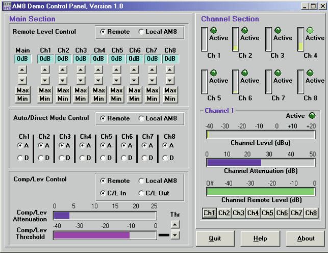
4.2.4 Parameter Im ”Remote”-Modus können Sie alle Parameter vom Computer
einstellen aus einstellen. Die Einstellung der Regler wird durch die
Einstellungen, die Sie am Computer vornehmen, ersetzt.
1. Klicken Sie in der Zeile ”Remote Level Control” auf
”Remote” und stellen Sie die Empfindlichkeit jedes Eingangs
ein.
2. Klicken Sie in derZeile ”Auto/Direct Mode Control” auf
”Remote” und klicken Sie bei jedem Kanal auf ”D” für manu-
ellen Betrieb oder ”A” für automatischen Betrieb.
Schalten Sie die Kanäle für Zuspielgeräte oder ein
Ansagemikrofon auf ”D”.
3. Klicken Sie in derZeile ”Comp/Lev Control” auf ”Remote”
und auf ”C/L In”, um den Kompressor/Leveler einzuschal-
ten.
Abb. 5: Parametermenü und
Anzeigefelder
Stellen Sie mit den Pfeiltasten unter ”Thr” die Einsatzschwelle ein. Wir empfehlen, die Einsatzschwelle nicht höher
als -12 dB einzustellen.
4. Im Anzeigefeld ”Channel Section” wird der Betriebszustand und Signalpegel jedes Kanals angezeigt.
Um zusätzliche Informationen einzublenden, klicken Sie auf eine der Tasten ”Ch1” bis ”Ch8” rechts unten, z.B.
”Ch1”.
Im Anzeigefeld ”Channel x” wird der Signalpegel (Channel Level), die momentane Dämpfung (Channel Attenuation)
und die externe Pegeleinstellung (Channel Remote Level) des gewählten Kanals (z.B. ”Channel 1”) angezeigt.
☞ Hinweis: Die LEVEL-Regler an der Frontplatte sind auch im ”Remote”-Modus wirksam. Der Regelbereich ist jedoch einge-
schränkt.
4.3 Externe 5. Speichern Sie Ihre Einstellungen, indem Sie auf ”Quit” klicken und die daraufhin erscheinenden Fragen mit ”Yes”
Bedienelemente oder ”No” beantworten.
Mit den externen Bedienelementen, die Sie an den AS 8 /AS 8 TC angeschlossen haben, können Sie den Pegel der ent-
sprechenden Kanäle regeln oder Kanäle stummschalten.
Die externen Bedienelemente sind immer wirksam, unabhängig davon, ob Sie den AS 8 / AS 8 TC im ”Local”- oder im
”Remote”-Modus betreiben.
41 Safety and Environment
1. Do not spill any liquids on the equipment and do not drop any objects through the ventilation slots in the equipment. 1.1 Safety
2. The equipment may be used in dry rooms only.
3. The equipment may be opened, serviced, and repaired by authorized personnel only. the equipment contains no
user-serviceable parts.
4. Before connecting the equipment to power, check that the AC mains voltage stated on the supplied AC adapter is
identical to the AC mains voltage available where you will use the equipment.
5. Operate the equipment with the supplied 20-V AC adapter. Using adapters with a DC output and/or a different out-
put voltage may cause serious damage to the unit.
6. If any solid object or liquid penetrates into the equipment, shut down the sound system immediately. Disconnect the
AC adapter from the power outlet immediately and have the equipment checked by AKG service personnel.
7. If you will not use the equipment for a long period of time, disconnect the AC adapter from the power outlet. Please
note that the equipment will not be fully isolated from power when you set the power switch to OFF.
8. Do not place the equipment near heat sources such as radiators, heating ducts, or amplifiers, etc. and do not ex-
pose it to direct sunlight, excessive dust, moisture, rain, mechanical vibrations, or shock.
9. To avoid hum or interference, route all audio lines, particularly those connected to the microphone inputs, away from
power lines of any type. If you use cable ducts, be sure to use separate ducts for the audio lines.
10. Clean the equipment with a moistened (not wet) cloth only. Be sure to disconnect the AC adapter from the power
outlet before cleaning the equipment! Never use caustic or scouring cleaners or cleaning agents containing alcohol
or solvents since these may damage the enamel and plastic parts.
11. Use the equipment for the applications described in this manual only. AKG cannot accept any liability for damages
resulting from improper handling or misuse.
1. The AC adapter will draw a small amount of current even when the equipment is switched off. To save energy, dis- 1.2 Environment
connect the AC adapter from the power outlet if you will leave the equipment unused for a long period of time.
2. When scrapping the equipment, separate the case, circuit boards, and cables, and dispose of all components in
accordance with local waste disposal rules.
2 Description
The AKG AS 8 is an 8-channel, single rack space automatic audio mixer. Using a unique mixing algorithm, the automatic 2.1 Introduction
mixing action is inaudible and very simple to set up. The AS 8 offers a range of remote control options including an
RS-232 port. In addition, the AS 8 is equipped with a sophisticated compressor/leveller for dynamic range control.
Multiple AS 8s can be coupled together for applications that call for more than eight microphone channels.
The AS 8 TC is identical to the AS 8 and provides separate HF and LF controls on each channel.
For more details refer to the AS 8 / AS 8 TC Owner's Manual.
1 x AS 8 or AS 8 TC 2.2 Packing List
1 x AC adapter
1 x CD-ROM with "LecNet for AKG" software
1 x RS-232 cable
1 x LecNet expansion cable
3 Installation and Interfacing
1. Install the unit in your 19” rack. 3.1 Rack Mounting
2. If you use only one unit, set the MASTER/SLAVE switch to "MASTER".
If you need more than eight microphone channels, you can 3.2 Daisy Chaining
couple several AS 8s /AS 8 TCs together.
1. Set the MASTER/SLAVE switch on the unit in the
highest slot in the rack to "MASTER". MASTER
2. Set the MASTER/SLAVE switches on all other units to
"SLAVE".
3. Use the supplied LecNet expansion cable to connect
the EXPANSION IN port on the "Master" to the EXPAN-
SION OUT port on the first "Slave" and so on as shown SLAVE
in fig. 1.
SLAVE Fig. 1: Daisy-chaining
several AS 8s
1. Connect your microphones and other audio sources to the CH 1 IN to CH 8 IN audio input terminals. All inputs are 3.3 Audio Connections
balanced. To connect unbalanced audio sources, connect the signal lead to the "+" terminal and the shield to both
the "-" and ground terminals.
2. If you use condenser microphones, check what supply voltage or what type of power supply they require.
If your condenser microphones will operate on +15 V phantom power, set the rear panel dip switch no. 2 for the
appropriate channel(s) to ON to switch phantom power for each condenser microphone on.
3. Connect the MAIN OUT terminals to the amplifier input. The output is balanced. To connect to an unbalanced inputs,
connect the hot wire of the cable to the "+" terminal and the shield to ground. Leave the "-" terminal floating!
53 Installation and Interfacing
Important! Each audio channel provides an unbalanced direct output called DIR. OUT. If you use the DIR. OUT terminals as
additional outputs, DO NOT connect the ground lead (shield) of the cable to the ground terminal of the respec-
➔
tive input but to the ground terminal of the MAIN OUT.
3.4 Connecting to the Use the supplied RS-232 cable to connect the RS-232 port on the AS 8 / AS 8 TC rear panel to the RS-232 port on your
Computer computer.
3.5 Connecting Remote The REMOTE LEVEL CONTROL 15-pin D-Sub connector
Level Controls on the rear panel of the unit allows you to control the level
of each channel separately or to mute channels individual-
ly. Depending on the application, you can use potentio-
meters, switches, or external control voltages.
Fig. 2 shows three examples:
Continuous level control of channel 1 using a 10 kΩ
linear pot.
Uext
Muting channel 5 with an SPST switch.
continuous level control of channel 7 using an external
DC control voltage (Uext = control voltage, = ground).
Fig. 2: Remote level control
example.
3.6 Connecting to 1. Connect the cable on the supplied AC adapter to the PWR IN jack on the AS 8 / AS 8 TC rear panel.
Power 2. Connect the AC adapter to a convenient power outlet.
4 Operating Notes
4.1 Local Mode You can set up and operate your AS 8 / AS 8 TC either in Remote mode from a computer or in Local mode using the
controls on the AS 8 / AS 8 TC itself. If you have not connected the AS 8 / AS 8 TC to a computer, you can set all
parameters on the unit itself as soon as you switched power to the unit on. If you connected the AS 8 / AS 8 TC to a
computer and installed the supplied software (refer to section 4.2), you will first have to click on "Local AS 8" in the main
menu.
Switch the unit ON with the POWER switch and adjust the various parameters:
Refer to the switch symbols 1. DIRECT/AUTO: The rear panel dip switch no. 1 toggles the appropriate channel between DIRECT (always on) mode
on the rear panel, above the and AUTO mode (the channel will be open for as long as somebody talks into the microphone). The ON LED illumi-
input terminals. nates for as long as the channel is active.
2. Phantom power: Dip switch no. 2 switches phantom power ON or OFF for each channel.
3. Input gain and level: Dip switches nos. 3 and 4 set the input gain for each channel in 3 steps (0 dB, +30 dB,
+60 dB).
The LEVEL rotary pot on the front panel adjusts the relative signal level of each channel.
4. Output level: The front panel OUTPUT LEVEL control sets the output level at the MAIN OUT terminals.
5. Compressor/Leveller: The COMP/LEVEL IN/OUT switch lets you switch the compressor/Leveller into (IN) or out of
circuit (OUT). The THRESHOLD control sets the compression threshold from 0 dB to –40 dB. We recommend using
THRESHOLD settings of –12 dB or lower.
The GAIN REDUCTION LEDs indicate the instantaneous amount of gain reduction applied to the output signal.
6. Tone controls (AS 8 TC only): The LF controls cut or boost the low frequency range for each channel, the HF con-
trols cut or boost the high frequency range.
7. Make sure the rear panel MASTER/SLAVE switch is in the correct position (refer to sections 3.1 and 3.2).
4.2 Remote Mode 1. Insert the CD-ROM into your drive. The installation program will start automatically.
(Computer Control) 2. Follow the on-screen instructions.
3. Enter your name and company name when asked and we you to accept the default directory.
4.2.1 Installing the 4. If you are not familiar with the LecNet software we recommend you to choose "Typical" installation.
Software 5. Click on "Next" and accept the given setting by double-clicking on "Next" again.
6. To complete the installation, click on "Finish" when asked for.
7. You can now start the software anytime by clicking on "Start/Program/LecNet for AKG".
4.2.2 Setting Up your Before starting the program:
Software • Check that the AS 8 / AS 8 TC is connected to your computer. If it is not, use the supplied RS-232 cable to connect
the AS 8 / AS 8 TC to the computer. Switch power to the AS 8 / AS 8 TC ON.
64 Operating Notes
• Prior to all manipulation and interconnection make sure you have equipped all the devices with a unique Important! ➔
address, a number between 128 and 256. To change an address, connect only one device to the computer
and set the MASTER/SLAVE switch to "MASTER" mode.
1. Launch the software at "Start/Programs/LecNet for AKG/LecNet Master 4.2.3 Selecting Devices
Pro" or double click on the shortcut to LecNet Master Pro you might have
created on your desktop.
The LecNet program will run a check to see which devices are connected
to your computer, thus automatically find the AS 8 / AS 8 TC you have link-
ed to your computer.
Fig. 3: Checking LecNet
Addresses…
2. In the Lecnet Master Pro screen that has popped up, click on
"Devices/Select Device…..".
The addresses of all your connected devices will pop up.
3. Click on the device you want to program.
This will get you to an active programming screen for your AS 8 / AS 8 TC.
Fig. 4: Programming screen
for the AS 8 / AS 8 TC.
In Remote mode, you can adjust all parameters from the com- 4.2.4 Adjusting
puter. The settings you make on the computer will override the Parameters
settings of the controls on the AS 8 /AS 8 TC.
1. In the "Remote Level Control" field, click on "Remote" and
set the input gain for each channel.
2. In the "Auto/Direct Mode control" field, click on "Remote"
and click on either "D for direct mode or "A" for automatic
control for each channel.
Set any channels that you use for audio sources or an
announcement microphone to "D".
3. In the "Comp/Lev Control" field, click on "Remote" and
"C/L In" to switch the compressor/leveller in.
Use the arrow buttons below "Thr" to set the compression
threshold. We recommend setting the threshold to –12 dB
or lower. Fig. 5: Parameter and
4. The "Channel Section" part of the screen shows the status metering screen.
and signal level of each channel.
To display additional information, click on one of the keys "Ch1" to "Ch8" at bottom right, for instance, "Ch1". The
"Channel x" field will indicate the Channel Level, Channel Attenuation, and Channel Remote Level of the selected
channel (in this example, "Channel 1").
The front panel LEVEL controls remain active in "Remote" mode, although their range is limited. Note: ☞
5. Save your settings by clicking on "Quit" and answering the questions appearing on the screen with "Yes" or "No".
The external controls you may have connected to the AS 8 / AS 8 TC allow you to adjust the signal level of or mute the 4.3 Remote Level
appropriate channels. Controls
The external controls are always active, no matter whether the AS 8 / AS 8 TC is in "Local" or "Remote" mode.
71 Sécurité et environnement
1.1 Sécurité 1. Attention de ne pas renverser de liquide ou de ne pas faire tomber un objet quelconque dans les fentes de ventila-
tion de l’appareil.
2. Cet appareil ne doit en aucun cas être utilisé dans un local humide.
3. Cet appareil ne peut être ouvert, entretenu et réparé que par le personnel technique autorisé. On ne trouve à
l’intérieur du boîtier aucun élément pouvant être entretenu, réparé ou remplacé par un profane.
4. Avant de mettre l’appareil en service, vérifiez si la tension de service indiquée sur l’adaptateur secteur fourni corre-
spond bien à la tension secteur sur le lieu d’utilisation.
5. N’utilisez jamais l’appareil avec une alimentation autre que l’adaptateur secteur pour courant alternatif et tension
sortie de 20 V c.a. fourni avec l’appareil. Tout autre type de courant ou de tension risqueraient de provoquer de
sérieux dégâts sur l’appareil !
6. S’il arrivait qu’un objet quelconque ou du liquide pénètre à l’intérieur de l’appareil, mettez immédiatement la chaîne hors
service. Débranchez aussitôt l’adaptateur secteur et faites réviser l’appareil par notre service après-vente.
7. Lorsque vous avez l’intention de rester quelque temps sans utiliser l’appareil, débranchez l’adaptateur secteur. Tant
que l’adaptateur est branché sur la prise secteur, l’appareil n’est pas entièrement coupé du secteur lorsque vous le
mettez hors tension.
8. Ne placez jamais l’appareil à proximité d’une source de chaleur (radiateurs, tuyaux de chauffage, amplis, etc.) et ne
l’exposez pas au rayonnement direct du soleil, à une atmosphère poussiéreuse ou humide, à la pluie, aux vibrations
ou aux chocs.
9. Pour éviter les parasites et les interférences, posez tous les fils, en particulier ceux des entrées micro, séparément
des câbles de puissance et des lignes de secteur. En cas de pose dans un puits ou une conduite pour câbles, les
câbles de transmission devront toujours être posés dans une conduite séparée.
10. Pour nettoyer l’appareil, utilisez un chiffon légèrement humide, jamais un chiffon mouillé. N’oubliez surtout bas de
débrancher auparavant l’adaptateur secteur ! N’utilisez jamais de produits de nettoyage mordants ou abrasifs, non plus
que des produits contenant de l’alcool ou un solvant qui risqueraient d’abîmer la laque et les éléments en plastique.
11. N’utilisez jamais l'appareil pour une application autre que celles indiquées dans le mode d’emploi. AKG décline toute res-
ponsabilité concernant les dégâts qui résulteraient d’une manipulation inappropriée ou d’une utilisation non conforme.
1.2 Environnement 1. L’adaptateur secteur consomme toujours un peu de courant même lorsque l’appareil est hors tension. Pour écono-
miser le courant, pensez donc à débrancher l’adaptateur du secteur lorsque l’appareil restera un certain temps sans
être utilisé.
2. Lorsque vous jetterez l’appareil, séparez le boîtier, l’électronique et les câbles et éliminez les différents éléments con-
formément à la réglementation en vigueur.
2 Description
2.1 Introduction L’AS 8 d’AKG est une console de mixage audio automatique 8 voies dans un boîtier 19" de 1 U de haut. L’algorithme
de mixage spécial offre un grand confort d’exploitation et évite les bruits gênants en fonctionnement automatique. L’AS
8 possède une interface RS-232 et des connecteurs pour toute une série de fonctions télécommandables. Elle com-
porte en outre un compresseur/leveler performant pour le réglage de la dynamique. L’AS 8 peut être cascadée pour réa-
liser des systèmes de sonorisation avec plus de 8 voies micro.
L’AS 8 TC possède en outre un réglage de timbre.
Pour des informations plus détaillées, veuillez vous reporter au manuel AS 8 / AS 8 TC en anglais.
2.2 Fournitures 1 AS 8 ou AS 8 TC
d’origine 1 adaptateur secteur
1 CD-ROM avec logiciel "LecNet for AKG"
1 câble RS 232
1 câble d’extension LecNet
3 Montage et raccordement
3.1 Montage en rack 1. Montez la console dans votre rack 19”.
2. Si vous utilisez une seule console, mettez le commutateur MASTER/SLAVE sur "MASTER".
3.2 Cascade Si vous avez besoin de plus de 8 voies micro, vous pouvez
cascader plusieurs AS 8/AS 8 TC.
1. Mettez le commutateur MASTER/SLAVE de la console
MASTER du haut sur "MASTER".
2. Sur les autres consoles, mettez le commutateur
MASTER/SLAVE sur "SLAVE".
3. Raccordez l’embase EXPANSION IN de l’AS 8 maître à
l’embase EXPANSION OUT de la première console
SLAVE esclave à l’aide du câble d’extension LecNet fourni,
comme indiqué à la Fig. 1.
Fig. 1: Cascade de SLAVE
plusieurs AS 8
83 Montage et raccordement
1. Raccordez vos micros et autres sources de signaux aux bornes d’entrée audio CH 1 IN à CH 8 IN. Les entrées sont 3.3 Bornes audio
symétriques mais il est néanmoins possible de raccorder des sources de signaux avec sorties asymétriques :
connectez le fil interne du câble sur "+" et le blindage sur "-" et à la masse.
2. Si vous utilisez des microphones électrostatiques vérifiez la tension d’alimentation ou les appareils d’alimentation
dont vous avez besoin.
Si vos microphones électrostatiques fonctionnent avec une alimentation fantôme de +15 V, mettez l’alimentation
fantôme en service en mettant le commutateur DIP 2 de la voie correspondante, au dos de la console, sur ON.
3. Raccordez les bornes MAIN OUT à l’entrée de l’ampli.
La sortie est symétrique. Pour le raccordement sur une entrée asymétrique, connectez le fil interne du câble sur "+"
et le blindage à la masse. La borne "-" reste libre!
Chaque voie audio a une sortie directe asymétrique DIR.OUT. Si vous utilisez les bornes DIR. OUT en tant que Important!
sorties supplémentaires, reliez le fil de masse du câble à la borne de masse de la sortie MAIN OUT et NON
➔
PAS à la borne de masse de l’entrée correspondante.
Raccordez le connecteur RS-232 au dos de l’AS 8/AS 8 TC au port RS-232 de votre ordinateur. 3.4 Raccordement à
l’ordinateur
L’embase 15 points Sub-D REMOTE LEVEL CONTROL au 3.5 Raccordement
dos de la console vous permet de régler séparément le d’éléments de
niveau de chaque voie de l’extérieur ou de muter des voies commande externes
séparément. Suivant le cas, vous pouvez utiliser à cet effet
des potentiomètres, des commutateurs ou des tensions de
commande externes.
La Fig 2 donne trois exemples :
Réglage de niveau en continu (voie 1) à l’aide d’un
potentiomètre linéaire de 10 kΩ Uext
Mise sur mute (voie 5) à l’aide d’un interrupteur mono-
polaire
Réglage du niveau en continu (voie 7) à l’aide d’une
tension de commande c.c. externe (Uext = tension de
commande, = masse)
Fig. 2 Exemple de fonctions
à commande externe
1. Branchez le câble de l’adaptateur secteur fourni sur l’embase PWR IN en face arrière du AS 8 / AS 8 TC. 3.6 Branchement au
2. Branchez l’adaptateur secteur sur une prise secteur. secteur
4 Instructions pour l’utilisation
Vous pouvez régler et piloter votre AS 8 / AS 8 TC soit à partir d’un ordinateur (mode "Remote") soit directement à l’ai- 4.1 Mode "Local"
de des éléments de commande de l’AS 8 / AS 8 TC (mode "Local"). Si votre AS 8 / AS 8 TC n’est pas branchée sur un
ordinateur, vous pouvez régler tous les paramètres directement sur la console dès qu’elle est sous tension. Si par con-
tre votre AS 8 / AS 8 TC est branchée sur un ordinateur, dès lors que le logiciel est installé (voir point 4.2), vous devrez
cliquer sur "Local AS 8" dans le menu principal.
Mettez la console sous tension à l’aide de l’interrupteur POWER et réglez les paramètres suivants :
1. Manuel/automatique : Le commutateur DIP 1 au dos de la console permet de régler chaque voie sur manuel (posi- Voir les symboles des com-
tion "DIRECT" – la voie est toujours en service) ou automatique (position "AUTO" – la voie n’est en service que pen- mutateurs au dos de la con-
dant qu’on parle dans le micro). La LED ON allumée indique que le canal est en service. sole, au-dessus des bornes
2. Alimentation fantôme : Le commutateur DIP 2 met pour chaque voie l’alimentation fantôme en service (position d’entrée.
ON) ou hors service (position OFF).
3. Sensibilité et niveau d’entrée : Les commutateurs DIP 3 et 4 permettent de régler pour chaque voie l’amplificati-
on d’entrée sur une des 3 valeurs : 0 dB, +30 dB ou +60 dB.
Le réglage LEVEL en façade s’utilise pour le réglage fin du niveau relatif du signal pour chaque voie.
4. Niveau sortie : Le niveau de sortie de la console aux bornes MAIN OUT se règle à l’aide du bouton OUTPUT LEVEL
en façade.
5. Compresseur/leveler : Le commutateur COMP/LEVEL IN/OUT vous permet de mettre le compresseur/leveler en
service (IN) ou hors service (OUT). Le réglage THRESHOLD permet de régler le seuil d’intervention entre 0 dB et –40
dB. Nous conseillons de ne pas choisir une valeur au-delà de -12 dB.
Les LED GAIN REDUCTION indiquent la réduction momentanée du niveau de sortie.
6. Réglage de timbre (sur AS 8 TC seulement) : Les boutons LF en façade permettent d’atténuer ou amplifier les
basses, les boutons HF d’atténuer ou amplifier l’aigu, séparément pour chaque voie.
94 Instructions pour l’utilisation
7. Vérifiez si le commutateur MASTER/SLAVE au dos de la console est bien sur la position voulue (voir points 3.1
et 3.2).
4.2 Mode "Remote" 1. Placez le CD-ROM fourni dans le lecteur de CD de votre ordinateur. Le programme d’installation démarre automa-
(commande par tiquement.
ordinateur) 2. Suivez les indications données sur l’écran.
3. Sur invite, écrivez votre nom et le nom de la société ; nous vous conseillons d’accepter le répertoire proposé pour
4.2.1 Installation du le programme.
logiciel 4. Si vous n’êtes pas familier du logiciel LecNet, nous vous conseillons de cliquer sur "Typical" pour faciliter l’installa-
tion.
5. Cliquez sur "Next" et acceptez le réglage prédéfini en cliquant encore deux fois sur "Next".
6. Sur invite, cliquez sur "Finish" pour terminer l’installation.
7. Vous pouvez maintenant lancer le programme en cliquant sur "Start/Programs/LecNet for AKG".
4.2.2 Configuration Avant de lancer le programme :
du logiciel • Contrôlez si l’AS 8/AS 8 TC est raccordée à l’ordinateur. Si ce n’est pas le cas, raccordez la console à l’ordinateur
à l’aide du câble RS-232 fourni. Mettez l’AS 8/AS 8 TC sous tension.
➔ Important! • Avant de choisir des paramètres ou de raccorder d’autres appareils, attribuez à chaque appareil une adresse
claire - un chiffre entre 128 et 256. Pour modifier une adresse vous ne devez avoir qu’un seul appareil rac-
cordé à l’ordinateur et le commutateur MASTER/SLAVE doit être sur "MASTER".
4.2.3 Choisir l’appareil 1. Lancez le programme avec "Start/Programs/LecNet for AKG/LecNet
Master Pro" ou par un double clic sur le raccourci que vous aurez éventu-
ellement mis sur votre écran.
Le programme LecNet vérifie quels sont les appareils raccordés à l’ordina-
teur et trouve donc automatiquement le AS 8 / AS 8 TC que vous avez rac-
cordé.
Fig. 3 : Vérifier les
appareils…
2. Cliquez sur "Devices/Select Device…" dans le menu "LecNet Master Pro".
On voit apparaître les adresses de tous les appareils raccordés.
3. Cliquez sur l’adresse de l’appareil que vous voulez programmer.
Vous arrivez ainsi à un menu de programmation actif pour le AS 8 / AS 8 TC.
Fig. 4 : Chercher le masque
de programmation pour
l’AS 8 / AS 8 TC…
4.2.4 Réglage des En mode "Remote", vous pouvez réglez tous les paramètres sur
paramètres l’ordinateur. La position de l’élément de réglage est remplacée
par celle que vous choisissez sur l’ordinateur.
1. Cliquez sur "Remote" dans la ligne "Remote Level Control"
et réglez la sensibilité de chaque entrée.
2. Cliquez sur "Remote" dans la ligne "Auto/Direct Mode
Control" et cliquez pour chaque voie sur "D" pour fonc-
tionnement manuel ou "A" pour fonctionnement automa-
tique.
Mettez les voies correspondant aux appareils audio ou à un
micro d’annonces sur "D".
3. Cliquez dans la ligne "Comp/Lev Control" sur "Remote" et
sur "C/L In" pour mettre en service le compresseur/Leveler.
A l’aide des touches fléchées réglez le seuil d’intervention
Fig. 5 : Menu paramètres et sous "Thr". Nous vous conseillons de ne pas choisir une
zones d’affichage valeur au-delà de -12 dB.
4. L’état de service et le niveau du signal sont indiqués pour chaque voie dans la zone d’affichage "Channel Section".
Pour obtenir des informations supplémentaires cliquez sur un des boutons "Ch1" à "Ch 8" en bas à droite, p.ex.
"Ch1".
Dans la zone d’affichage "Channel x" sont affichés le niveau du signal (Signal Level), l’atténuation momentanée
(Channel Attenuation) et la valeur de réglage externe du niveau (Channel Remote Level) pour la voie sélectionnée.
☞ Remarque: Les boutons LEVEL en façade ont également un effet en mode "Remote", mais avec une plage de réglage limitée.
5. Enregistrez vos réglages en cliquant sur "Quit" et en répondant par "Yes" ou "No" aux questions qui s’affichent.
4.3 Eléments de Les éléments de commande externes que vous avez raccordé à votre AS 8 / AS 8 TC vous permettent de régler le niveau
commande externes des voies correspondantes ou de muter les canaux.
Les éléments de commande externes sont toujours opérationnels, que vous utilisiez le mode "Local" ou "Remote".
101 Sicurezza ed ambiente
1. Non fate entrare liquidi nell’apparecchio e non fate entrare oggetti attraverso le fessure di ventilazione. 1.1 Sicurezza
2. L’apparecchio deve venir adoperato solo in vani asciutti.
3. L’apparecchio può venir aperto, mantenuto e riparato solo da personale specializzato autorizzato. All’interno dell’-
apparecchio non vi sono componenti che possano venir mantenuti, riparati o sostituiti da non esperti.
4. Prima di mettere in esercizio l’apparecchio, controllate se la tensione d’esercizio indicata sull’alimentatore a spina in
dotazione corrisponde alla tensione di rete del luogo d’impiego.
5. Gestite l’apparecchio esclusivamente con l’alimentatore a spina a corrente alternata in dotazione, con una tensione
di uscita di 20 V c.a. Altre tensioni o altri tipi di corrente potrebbero danneggiare seriamente l’apparecchio!
6. Se un oggetto solido o un liquido dovesse entrare nell’interno dell’apparecchio, interrompete subito l’esercizio
dell’impianto. Sfilate in questo caso subito l’alimentatore a spina dalla presa e fate controllare l’apparecchio dal
nostro servizio assistenza clienti.
7. In caso di non-uso prolungato staccate l’alimentatore a spina dalla presa. Tenete presente che anche se spegnete
l’apparecchio, esso non viene staccato completamente dalla rete fin quando l’alimentatore a spina rimane inserito.
8. Non posizionate l’apparecchio nelle vicinanze di fonti di calore, come p.e. radiatori, tubi di riscaldamento, amplifi-
catori ecc. e non esponetelo all’irradiazione diretta del sole, a polvere o forte umidità, pioggia, vibrazioni o colpi.
9. Per evitare disturbi, risp. correnti di dispersione, posate tutte le linee, in particolare quelle degli ingressi microfonici,
separatamente da linee di corrente ad alta tensione e linee di rete. Nel caso di posa di linee in pozzi o in canali per
cavi fate attenzione a sistemare le linee di trasmissione in un canale separato.
10. Pulite l’apparecchio solo con un panno umido, ma non bagnato. Prima di farlo, dovete assolutamente staccare l’ali-
mentatore a spina dalla presa! Non usate in nessun caso detergenti acidi o abrasivi o detergenti contenenti alcool o
solventi perché potrebbero danneggiare la vernice e i componenti in materia sintetica.
11. Usate l'apparecchio solo per gli impieghi descritti nelle presenti istruzioni per l’uso. La AKG non assume nessuna
responsabilità per danni causati da manipolazione non effettuata a regola d’arte o da uso non corretto.
1. L’alimentatore a spina assorbe piccole quantità di corrente anche quando è spento. Per risparmiare energia, stac- 1.2 Ambiente
cate quindi l’alimentatore a spina dalla presa se non usate l’apparecchio per un periodo prolungato.
2. Se rottamate l’apparecchio, fate la cernita di scatola, parti elettroniche e cavo e smaltite tutti i componenti secondo
le norme di smaltimento vigenti al riguardo.
2 Descrizione
L’AS 8 della AKG è un mixer audio automatico ad 8 canali in una scatola da 19" di 1 unità d’altezza. Lo speciale algo- 2.1 Introduzione
ritmo di mixaggio offre alto confort di gestione ed impedisce fastidiosi rumori collaterali durante l’esercizio automatico.
L’AS 8 è dotato di un’interfaccia RS-232 e di collegamenti per una serie di funzioni telecomandabili. Inoltre, l’AS 8 è dota-
to di un pregiato compressor/leveler per regolare la dinamica. Per poter configurare impianti di sonorizzazione con più
di 8 canali microfonici, l’AS 8 può essere collegato in cascata.
L’AS 8 TC è dotato inoltre di una regolazione del suono.
Informazioni più dettagliate sull’apparecchio e sul suo esercizio sono contenute nel manuale AS 8 /AS 8 TC in lingua
inglese.
1 x AS 8 o AS 8 TC 2.2 In dotazione
1 x alimentatore a spina
1 x CD-ROM con software "LecNet for AKG"
1 x cavo RS-232
1 x cavo di ampliamento LecNet
3 Montaggio e collegamento
1. Montate l’apparecchio nel vostro rack di 19”. 3.1 Montaggio in rack
2. Se usate solo un apparecchio, portate l’interruttore MASTER/SLAVE in posizione "MASTER".
Se avete bisogno di più di 8 canali microfonici, potete col- 3.2 Collegamento in
legare in cascata più AS 8 / AS 8 TC. cascata
1. Sull’apparecchio più in alto portate l’interruttore
MASTER/SLAVE in posizione "MASTER". MASTER
2. Sugli altri apparecchi portate l’interruttore
MASTER/SLAVE in posizione "SLAVE".
3. Collegate, con l’aiuto del cavo d’espansione LecNet in
dotazione, la presa EXPANSION IN disposta sul
"Master"-AS 8 alla presa EXPANSION OUT disposta sul SLAVE
primo "Slave" e così via, come raffigurato nella fig. 1.
SLAVE Fig. 1: Collegamento in
cascata di più AS 8
113 Montaggio e collegamento
3.3 Collegamenti audio 1. Collegate i vostri microfoni e le altre fonti di segnale ai morsetti d’ingresso audio CH 1 IN - CH 8 IN. Gli ingressi sono
simmetrici, potete comunque collegare anche fonti di segnale con uscita asimmetrica: collegate il filo interno del
cavo a "+" e la schermatura a "-" e alla massa. Leggete al riguardo le istruzioni per l’uso del rispettivo microfono o
apparecchio.
2. Se usate microfoni a condensatore, verificate di quale tensione di alimentazione o di quali apparecchi di alimenta-
zione hanno bisogno.
Se i vostri microfoni a condensatore sono adatti per l’alimentazione phantom da +15 V, inserite l’alimentazione phan-
tom portando l’interruttore dip 2 del rispettivo canale sul retro dell’apparecchio in posizione ON.
3. Collegate i morsetti MAIN OUT all’ingresso dell’amplificatore. L’uscita è simmetrica. Per il collegamento ad un
ingresso asimmetrico collegate il filo interno del cavo a "+" e la schermatura alla massa.
Lasciate libero il morsetto "-"!
Importante! Ogni canale audio è dotato di un’uscita diretta asimmetrica DIR. OUT. Se usate i morsetti DIR. OUT come uscite
addizionali, NON collegate il filo di massa del cavo al morsetto di massa del rispettivo ingresso, ma al morsetto di
➔
massa dell’uscita MAIN OUT.
3.4 Collegamento al Collegate la presa RS-232 disposta sul retro dell’AS 8 / AS 8 TC al port RS-232 disposto sul vostro computer.
computer
3.5 Collegamento di La presa Sub-D a 15 poli REMOTE LEVEL CONTROL dis-
elementi di comando posta sul retro dell’apparecchio vi permette di regolare
esterni dall’esterno e separatamente il livello di ogni canale oppu-
re di silenziare singoli canali. A seconda dell’applicazione,
potete impiegare al riguardo potenziometri, interruttori o
tensioni di comando esterne.
La fig. 2 illustra tre esempi:
Regolazione continua del livello (canale 1) mediante
potenziometro lineare da 10 kΩ
Uext Silenziamento (canale 5) mediante interruttore on/off ad
un polo
Regolazione continua del livello (canale 7) mediante ali-
mentazione di comando c.c. esterna (Uext = tensione di
comando, = massa)
Fig. 2 Esempio di funzioni
esterne telecomandate
3.6 Collegamento 1. Collegate il cavo dell’alimentatore a spina in dotazione alla presa PWR IN disposta sul lato posteriore del
alla rete AS 8 / AS 8 TC.
1. Inserite l’alimentatore a spina ad una presa di rete.
4 Istruzioni per l’esercizio
4.1 Modo "Local" Potete regolare o gestire il vostro AS 8 risp. AS 8 TC o con un computer (modo "Remote") oppure con gli elementi di
comando disposti sull’AS 8 / AS 8 TC stesso (modo "Local"). Se non avete collegato l’AS 8 / AS 8 TC ad un computer,
subito dopo l’inserimento potete regolare tutti i parametri sull’apparecchio stesso. Se avete collegato l’AS 8 / AS 8 TC
ad un computer e se avete installato il software in dotazione (vedi capitolo 4.2), dovete cliccare nel menù principale su
"Local AS 8".
Inserite l’apparecchio con l’aiuto dell‘interruttore POWER e regolate i singoli parametri:
Vedi i simboli degli interrut- 1. Manuale/automatico: l’interruttore dip 1 disposto sul retro dell’apparecchio porta il rispettivo canale o in esercizio
tori disposti sul retro sopra i manuale (posizione "DIRECT" – il canale è sempre aperto) o in esercizio automatico (posizione "AUTO" – il canale
morsetti d’ingresso. rimane inserito solo fin quando si parla nel microfono). Il LED ON rimane acceso fin quando il canale è inserito.
2. Alimentazione phantom: l’interruttore dip 2 inserisce l’alimentazione phantom per ogni canale (posizione ON) e la
disinserisce (posizione OFF).
3. Sensibilità e livello d‘ingresso: gli interruttori dip 3 e 4 regolano l’amplificazione d’ingresso per ogni canale in tre
stadi (0 dB, +30 dB, +60 dB).
Il regolatore LEVEL disposto sul pannello frontale serve alla regolazione fine del livello di segnale relativo per ogni
canale.
4. Livello d’uscita: potete regolare il livello d’uscita dell’apparecchio presente ai collegamenti MAIN OUT con il rego-
latore OUTPUT LEVEL disposto sul pannello frontale.
5. Compressor/leveler: Con l’interruttore COMP/LEVEL IN/OUT potete inserire il compressor/leveler (IN) e disinserir-
lo (OUT). Il regolatore THRESHOLD regola la soglia d’inserzione da 0 dB a -40 dB. Raccomandiamo di non regola-
re la soglia d’inserzione sopra i -12 dB.
I LED GAIN REDUCTION indicano l’attuale riduzione del livello d’uscita.
124 Istruzioni per l’esercizio
6. Regolazione del suono (solo per l‘AS 8 TC): Con i regolatori LF disposti sul pannello frontale potete ridurre ed
enfatizzare, per ogni canale separatamente, i bassi, con i regolatori HF gli alti.
7. Controllate se l’interruttore MASTER/SLAVE disposto sul retro è nella corretta posizione (vedi capitoli 3.1 e 3.2).
1. Inserite il CD-ROM in dotazione nel drive CD del vostro computer. Il programma di installazione si avvia automati- 4.2 Modo "Remote"
camente. (comando con
2. Seguite le istruzioni sullo schermo. computer)
3. Se invitati, immettete il vostro nome ed il nome della ditta; raccomandiamo di accettare l’elenco proposto per il pro-
gramma. 4.2.1 Installazione del
4. Se non siete familiari del software LecNet, raccomandiamo di cliccare su "Typical" per facilitare l’installazione. software
5. Cliccate su "Next" ed accettate la regolazione prestabilita cliccando ancora due volte su "Next".
6. Se invitati, cliccate su "Finish" per terminare l‘installazione.
7. Potete ora avviare il software in qualsiasi momento cliccando su "Start/Programs/LecNet for AKG".
Prima di avviare il programma: 4.2.2 Configurazione del
• Controllate se l’AS 8 / AS 8 TC è collegato al computer. Se no, collegate l’apparecchio con l’aiuto del cavo RS-232 software
in dotazione al computer. Inserite l’AS 8 / AS 8 TC.
• Prima di regolare dei parametri o di collegare apparecchi addizionali, assegnate ad ogni apparecchio un indi- Importante! ➔
rizzo inequivocabile – un numero tra 128 e 256. Per cambiare l’indirizzo, solo un apparecchio deve essere col-
legato al computer e l’interruttore MASTER/SLAVE deve essere in posizione "MASTER".
1. Avviate il programma servendovi di "Start/Programs/LecNet for 4.2.3 Scegliere
AKG/LecNet Master Pro" o cliccando due volte sul comando breve se l’a- l'apparecchio
vete installato sul vostro desktop.
Il programma LecNet controlla quali apparecchi sono collegati al computer
e trova poi automaticamente quel AS 8 / AS 8 TC che avete collegato al
computer.
Fig. 3: Controllare gli
indirizzi …
2. Nel menù "LecNet Master Pro" cliccate su "Devices/Select Device …".
Vengono visualizzati gli indirizzi di tutti gli apparecchi collegati.
3. Cliccate sull’indirizzo di quell’apparecchio che volete programmare. Così
arrivate ad un menù di programmazione attivo per il AS 8 / AS 8 TC.
Fig. 4: Per la maschera di
programmazione del AS 8 /
AS 8 TC …
Nel modo "Remote" potete regolare tutti i parametri via com- 4.2.4 Regolazione dei
puter. La regolazione per mezzo dei regolatori è sostituita dalle parametri
regolazioni effettuate via computer.
1. Nella riga "Remote Level Control" cliccate su "Remote" e
regolate la sensibilità di ogni ingresso.
2. Nella riga "Auto/Direct Mode Control" cliccate su "Remote"
e per ogni canale cliccate su "D" per l’esercizio manuale o
su "A" per l’esercizio automatico.
Portate i canali per apparecchi audio esterni o microfoni per
annunci su "D".
3. Nella riga "Comp/Lev Control" cliccate su "Remote" e su
"C/L In" per inserire il compressor/leveler.
Con i tasti freccia regolate, alla voce "Thr", la soglia d’ins-
erzione. Raccomandiamo di non regolare la soglia d’inser-
zione sopra i -12 dB. Fig. 5: Menù dei parametri e
4. Nel quadro di visualizzazione "Channel Section" è indicato quadri di visualizzazione
lo stato d’esercizio ed il livello del segnale di ogni canale.
Per visualizzare ulteriori informazioni, cliccate su uno dei tasti da "Ch1" a "Ch8" disposti sul lato destro inferiore, p.e.
su "Ch1".
Nel quadro di visualizzazione "Channel x" è indicato il livello del segnale (Channel Level), l’attenuazione attuale (Channel
Attenuation) e la regolazione esterna del livello (Channel Remote Level) del canale prescelto (p.e. "Channel 1").
I regolatori LEVEL disposti sul pannello frontale spiegano il loro effetto anche nel modo "Remote". Il campo di rego- Avvertenza: ☞
lazione è comunque limitato.
5. Memorizzate le vostre regolazioni cliccando su "Quit" e rispondendo alle questioni che appaiono in seguito con
"Yes" o "No".
Con gli elementi di comando esterni collegati all’AS 8 / AS 8 TC potete regolare il livello dei rispettivi canali oppure silen- 4.3 Elementi di comando
ziare dei canali. esterni
Gli elementi di comando esterni spiegano sempre il loro effetto, indipendentemente dal fatto se l’AS 8 / AS 8 TC lavora
nel modo "Local" o "Remote".
13Sie können auch lesen