Bedienungsanleitung Caravanman Kompakt 3
←
→
Transkription von Seiteninhalten
Wenn Ihr Browser die Seite nicht korrekt rendert, bitte, lesen Sie den Inhalt der Seite unten
Caravanman Kompakt 3
Bedienungsanleitung

Inhaltsverzeichnis

     1. Einführung
        1.1 Sicherheitshinweise............................................................................. 03
        1.2 Lieferumfang......................................................................................... 03
        1.3 Systemkomponenten.......................................................................... 04

     2. Installation
        2.1 Installation auf dem Dach.................................................................. 05
        2.2 Klebeanleitung...................................................................................... 06
        2.3 Installation im Innenbereich.............................................................. 07
        2.4 Anschluss der Komponenten............................................................ 08
        2.5 Das Steuergerät.................................................................................... 10
        2.6 Satellitenübertragung......................................................................... 11

     3. Satellitensuche mit dem Steuergerät
        3.1 Bezeichnung der jeweiligen LEDs und Tasten.............................. 12
        3.2 Satellitensuche..................................................................................... 13

     4. Mobil-App zur Steuerung der Antenne
        4.1 Steuergerät mit dem Mobilgerät verbinden................................. 14
        4.2 Firmware-Update der Antenne........................................................ 16
        4.3 Satellit wechseln................................................................................... 17
        4.4 Bluetooth®-Verbindung trennen...................................................... 17

     5. Fehlerbehebung........................................................................................ 18

     6. Einstellwerte für den Skew................................................................... 19

     7. Ausleuchtzone........................................................................................... 20

     8. Montageabmessungen........................................................................... 21

     9. Technische Daten..................................................................................... 22

02                                                  DEUTSCH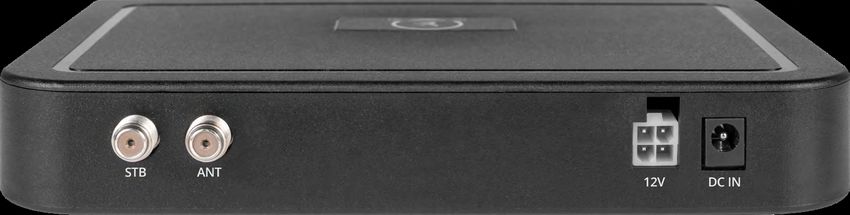
1. Einführung
1.1 Sicherheitshinweise
Lesen Sie das Benutzerhandbuch sorgfältig durch, bevor Sie mit der In-
stallation beginnen. Falls Sie schon ähnliche Produkte installiert haben,
muss die Vorgehensweise mit diesem Produkt nicht übereinstimmen.
Unsachgemäße Handhabung kann zu schweren Schäden an diesem Gerät
führen. Die Verantwortlichen können auch für daraus resultierende weitere
Schäden am Gerät verantwortlich gemacht werden.
Vor Inbetriebnahme überprüfen Sie bitte die richtige Betriebsspannung Ih-
res Stromanschlusses. Die Betriebsspannung des Gerätes entnehmen Sie
bitte den technischen Daten in dieser Bedienungsanleitung.
Das Steuergerät darf keinem Tropfwasser, Spritzwasser oder sonstigen Flüs-
sigkeiten ausgesetzt werden.
Lassen Sie Kinder nicht mit Folien oder anderen Verpackungsmaterialien
spielen, es besteht Erstickungsgefahr.
1.2 Lieferumfang
1x Caravanman Kompakt 3
1x Steuergerät inkl. Stromkabel Optionales Zubehör:
1x Koaxialkabel (1 m) Mobil-Kit 3 zur
1x Koaxialkabel (10 m) mobilen Nutzung
1x Dachdurchführung
1x Bedienungsanleitung
Art-Nr.: 1201000
DEUTSCH 03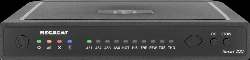
1. Einführung

 1.3 Systemkomponenten

Öffnen Sie den Karton und entnehmen Sie das Steuergerät, die Anschlusska-
bel und das Verpackungsmaterial. Heben Sie die Antenne gerade nach oben
aus dem Karton. Stellen Sie die Anlage niemals auf den Kopf!

                                             ACHTUNG!
                                             Fassen Sie die Antenne niemals
                                             direkt am Spiegel an, wenn Sie
                                             sie aus dem Karton heben.
                                             Heben Sie die Antenne an der
                                             Grundplatte an.

              Antenneneinheit
              Die Hochleistungsantenne und der Elevationswinkel von 15-
              62° ermöglichen bestmöglichen Empfang in den wichtigsten
              Urlaubsländern Europas.

              Steuergerät
              Das Steuergerät dient zur Satellitenauswahl und Steuerung. Es
              wird zwischen Antenne und TV (Receiver) geschaltet und ver-
              sorgt die Antenne mit Strom. Nach erfolgreicher Ausrichtung
              kann das Gerät ausgeschaltet werden.

 Hinweis:
 Der Caravanman Kompakt 3 Twin besitzt zusätzlich einen weiteren Anschluss
 für einen zweiten Fernseher bzw. Receiver. Für den korrekten Anschluss der
 Komponenten beachten Sie bitte das Anschlussdiagramm in dieser Bedie-
 nungsanleitung.

04                               DEUTSCH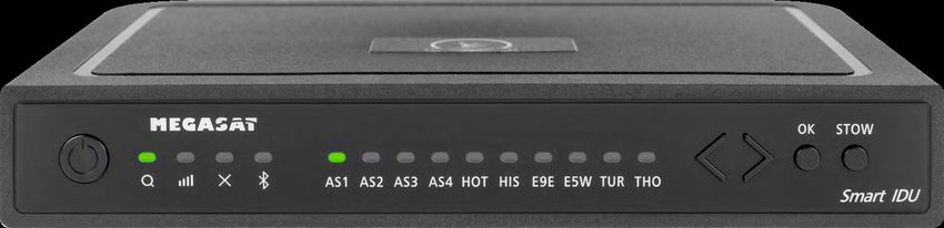
2. Installation
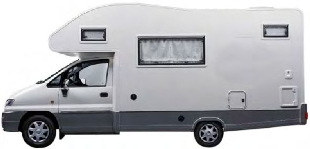
2.1 Installation auf dem Dach
Grundsätzlich empfehlen wir den Einbau durch Ihren Fachhändler
oder eine Fachwerkstatt vornehmen zu lassen! Beachten Sie bitte
auch, dass sich durch die Antenne die Fahrzeughöhe entsprechend
ändert! Bitte halten Sie sich unbedingt an die einzelnen Punkte der
Montageanweisung!
Allgemeines
Sorgen Sie für einen geeigneten Arbeitsplatz, eine Garage/Halle ist besser als
ein Platz im Freien. Die Umgebungstemperatur zur Montage muss zwischen
+5° C und max. +25° C liegen. Arbeiten Sie nicht direkt in der Sonne. Halten Sie
die Arbeitsvorschriften beim Umgang mit Chemieprodukten ein. Sorgen Sie für
die notwendige Arbeitshygiene.
Vorbereitung
1. Vergewissern Sie sich, dass das Dach Ihres Fahrzeugs ausreichend stabil
ist. Bei ungenügender oder zweifelhafter Dachstabilität ist ein ca. 2 mm
starkes Blech mit ca. 100 x 100 cm auf der Dachaußenhaut zu befestigen.
Erkundigen Sie sich dazu bei Ihrem Fahrzeughersteller.
2. Prüfen Sie, ob alle Teile vorhanden sind.
3. Setzen Sie die Antenne auf den späteren
Montageplatz und richten Sie sie so aus,
dass der Spiegel und die LNB-Einheit in
Richtung Heck des Fahrzeuges zeigen.
Achten Sie darauf, dass die Montageflä-
che eben ist und keine Dachaufbauten
im Weg sind. Beachten Sie unbedingt
die Montageabmessungen in dieser
Anleitung. Der Mindestabstand zu einer
Klimaanlage sollte 30 cm betragen.
4. Säubern Sie die Montagefläche mit
einem geeigneten Reiniger und einem
Vliestuch um Schmutz und Unreinheiten
zu entfernen. Zeichnen Sie anschließend
den Antennenfuß mit einem Stift an.
DEUTSCH 05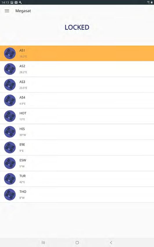
2. Installation
5. Rauen Sie die gezeichneten Flächen und Füße mit Schleifpapier (120er Kör-
   nung) leicht an und säubern Sie die Fläche erneut mit dem Reiniger und
   lassen Sie den Reiniger ca. 10 Minuten ablüften. ACHTUNG: Flächen an-
   schließend nicht mehr berühren.
6. Montieren Sie die Dachdurchführung (am besten im Windschatten hinter
   der Antenne) auf dem Fahrzeugdach. Es ist darauf zu achten, dass das Ein-
   dringen von Wasser und Feuchtigkeit (z. B. Regen oder Spritzwasser) im
   Bohrloch vermieden werden muss. Achten Sie darauf, dass die Kabel nicht
   zu sehr gebogen werden um Signalverlust und eine Beschädigung des Ka-
   bels zu vermeiden (kleinster Biegeradius max. 5-7 cm).

 2.2 Klebeanleitung

1. Bereiten Sie den Kleber für die Montage vor.

2. Tragen Sie nun den Kleber auf die Unterseite
   des Antennenfußes in Schlangenlinien auf, da-
   mit der Kleber bis ins Innere gut aushärten kann.

3. Setzen Sie nun sofort (innerhalb von 5 Minuten nach Kleberauftrag) die An-
   tenne auf das angezeichnete Feld. Drücken Sie den Fuß leicht und gleichmä-
   ßig an und fixieren Sie die Antenne, damit sie nicht verrutscht, z.B. durch ein
   Klebeband. Es müssen sich nach dem Andrücken noch mindestens 2 mm
   Kleber zwischen Antennenfuß und Oberfläche befinden. Der Kleber ist
   nach max. 48 Stunden bei +18° C und einer relativen Luftfeuchte von 50%
   ausgehärtet. Sollte während der Montagezeit eine geringe Luftfeuchtigkeit
   herrschen, sprühen Sie nach dem Verkleben in der Umgebung der Antenne
   immer wieder etwas Wasser in die Luft.

4. Entfernen Sie die evtl. ausgetretene Klebemasse sofort mit einer Spachtel
   oder Ähnliches und säubern Sie die verunreinigten Flächen mit dem Reini-
   ger und einem Vliestuch.

5. Zur Sicherheit können Sie den Antennenfuß zusätzlich befestigen. Dazu
   bohren Sie durch die vorhandenen Löcher im Antennenfuß in das Dach
   Ihres Fahrzeuges und fixieren es durch eine Schraube mit Kontermutter.
   Damit der frisch verklebte Fuß nicht verrutscht, warten Sie mit dieser Arbeit
   bis der Kleber ausgehärtet ist.

6. Nach der kompletten Montage und Aushärtung des Klebers, kann eine Sili-
   konfuge um den Antennenfuß gezogen werden.

06                                  DEUTSCH
2. Installation
2.3 Installation im Innenbereich
1. Das Koaxialkabel wird im Inneren des Fahrzeuges verlegt.
2. Vergewissern Sie sich bei der Wahl des Standortes für das Steuergerät und
den Sat-Receiver, dass beide Geräte an einem trockenen und geschützten
Ort stehen.
3. Das Steuergerät und den Sat-Receiver nicht in die Nähe von Wärmequellen
stellen und für ausreichend Belüftung sorgen.
4. Im Folgenden werden die grundlegenden Anschlussmöglichkeiten für die
Antennenanlage gezeigt:
Verbinden Sie die Stromversorgung (rot-schwarzes Kabel) für das Steu-
ergerät mit Ihrer Batterie des Fahrzeuges über eine Sicherung (7 Amper),
um einen Kabelbrand bei Kurzschluss zu vermeiden. Das gelbe Kabel
wird an dem Zündungsplus des Fahrzeuges angeschlossen und eben-
falls mit einer Sicherung von 7 Ampere abgesichert (Dieses Kabel muss
nur angeschlossen werden, wenn die Antenne automatisch bei Motor-
start einfahren soll.). Das übrig bleibende schwarze Kabel wird an den
dazugehörigen Minuspol der Zündungsanlage (Masse) angeschlossen.
Verbinden Sie das Koaxialkabel von der Antenne mit dem Steuergerät
(10 m Koaxialkabel mit F-Stecker in „ANTENNA“)
Verbinden Sie das Steuergerät mit dem Fernseher bzw. Sat-Receiver
(1 m Koaxialkabel mit F-Stecker von „RECEIVER“ zum Sat-Receiver)
Hinweis:
Beim Caravanman Kompakt 3 Twin schließen Sie ein zweites Koaxialkabel
von der Antenne direkt an den zweiten Fernseher bzw. Sat-Receiver an.
DEUTSCH 07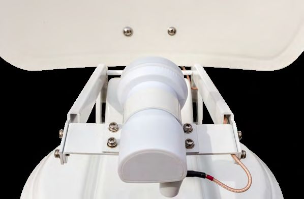
2. Installation

 2.4 Anschluss der Komponenten

Zündungsplus
Die Antenne fährt automatisch in den eingefahrenen Zustand, sobald der
Zündschlüssel gedreht wird. Diese Funktion ist nur gewährleistet, wenn das
Steuergerät eingeschaltet und Kabel 4 und 5 am Zündungsplus des Fahrzeugs
angeklemmt sind.

Stromversorgung
DC 12 V über Batterie (Pluspol Dauerversorgung ROT) oder optionales 230 V /
12 V DC Netzteil (Keine Ladegeräte). Achten Sie darauf, dass eine Stromstärke
von mind. 5 Ampere gewährleistet ist.

     1         Koaxialkabel 10 m
     2         Koaxialkabel 1 m
     3         Pluspol
     4         Minuspol
     5         Zündungsplus

         Achtung: Schließen Sie das Steuergerät immer über eine mit 7 Ampere
         abgesicherte und mind. 2,5 mm² starke Leitung an. Niemals ohne Siche-
         rung an die Autobatterie anschließen.

08                                 DEUTSCH
2. Installation

                                                             Fernseher 2
      Control-Box

                    Receiver

                                 Zweiter Anschluss nur bei
                               Caravanman Kompakt 3 Twin.
                                   Koaxialkabel NICHT im
                                  Lieferumfang enthalten!

       1                               2

                                                             Fernseher 1

                                           (–) (+)
      ANT

                    STB

                                   4
                                                 5
                                                 4
     Steuergerät                   3
                                           (+) (–)

                                       DEUTSCH                             09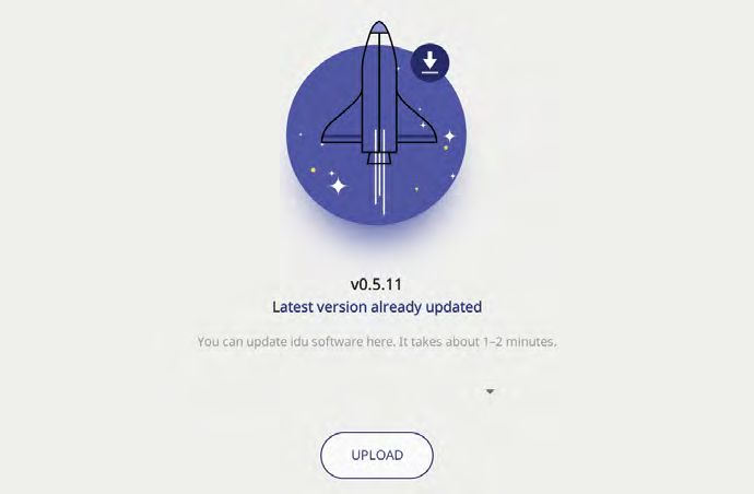
2. Installation

 2.5 Das Steuergerät

Standby-Taste         Aktueller Satellit       Satellitenauswahl   Bestätigung

          Status-LEDs                                          Grundposition
                                                             (fährt die Antenne ein)

                                                        Anschluss für externes
       Anschluss zur Antenne                              Netzteil (optional)

     Anschluss zum                                  Stromversorgung
      TV / Receiver                                     (12 Volt)

        Achtung: Schließen Sie das Steuergerät immer über eine mit 7 Ampere
        abgesicherte und mind. 2,5 mm² starke Leitung an. Niemals ohne Siche-
        rung an die Autobatterie anschließen.

10                                   DEUTSCH
2. Installation
2.6 Satellitenübertragung
Direct Broadcast Service (DBS) strahlt Audio, Video und Daten über den Satel-
liten aus, der sich in 35.000 km Höhe über der Erde befindet. Mit einer Emp-
fangsstation wie der Antenne und einem Satelliten Receiver werden die Signa-
le vom Satelliten empfangen und verarbeitet. Das System erfordert eine klare
Sicht auf den Satelliten, um den Signalempfang maximal auszunutzen.
Gutes Empfangssignal Schlechtes Empfangssignal
Objekte wie Bäume, Brücken und große Häuser, die sich im Einfallswinkel des
Satelliten befinden, führen zu einem Verlust des Signals. Starker Regen, Wol-
ken, Schnee oder Eis kann die Empfangsqualität beeinträchtigen. Wenn das
Satellitensignal durch schwere Wetterbedingungen verloren geht, wird das
laufende Programm des Receivers beendet (das Bild wird einfrieren, bzw. ver-
schwinden). Wenn die Witterungsverhältnisse wieder einen guten Empfang
ermöglichen, wird das TV Bild wieder hergestellt.
DEUTSCH 113. Satellitensuche mit dem Steuergerät
3.1 Bezeichnung der jeweiligen LEDs und Tasten
Such-LED Satelliten-LED
Blinkt während der Satelliten-Suche AS4 Astra 4 (4° Ost)
Empfangs-LED Satelliten-LED
Leuchtet bei gefundenem Satelliten HOT Hotbird (13° Ost)
Error-LED Satelliten-LED
Leuchtet bei einer Fehlfunktion HIS Hispasat (30° West)
Bluetooth-LED Satelliten-LED
Leuchtet bei Verbindung E9E Eutelsat 9 B (9° Ost)
Satelliten-LED Satelliten-LED
AS1 Astra 1 (19,2° Ost) E5W Eutelsat 5 West (5° West)
Satelliten-LED Satelliten-LED
AS2 Astra 2 (28,2° Ost) TUR Türksat (42° Ost)
Satelliten-LED Satelliten-LED
AS3 Astra 3 (23,5° Ost) THOR Thor (0,8° West)
Standby-Taste OK-Taste
Schaltet das Steuergerät ein / aus Bestätigt die Satellitenauswahl
Pfeil-Tasten STOW-Taste
Wechsel der Satelliten Fährt die Antenne in die Grundposition
12 DEUTSCH3. Satellitensuche mit dem Steuergerät
3.2 Satellitensuche
1. Schalten Sie das Steuergerät an der Standby-Taste ein.
2. Die Such-LED blinkt während des Suchvorgangs grün.
3. Die Satelliten-LED des zuletzt vewendeten Satelliten blinkt grün.
Um den Satelliten zu wechseln, müssen Sie innerhalb von ca. 3-5 Sek.,
während die LEDs blinken, den Satelliten mit den Pfeiltasten wechseln.
4.
Später ist ein Wechsel nur möglich, wenn die Antenne zuvor einen
Satelliten gefunden hat.
Bestätigen Sie die Satellitenauswahl mit der OK-Taste, oder warten
5.
Sie 3-5 Sekunden bis sich der Satellit automatisch einloggt.
Nachdem der gewählte Satellit gefunden wurde, leuchtet die Emp-
6.
fangs-LED orange.
Wurde der gewählte Satellit nicht gefunden, leuchtet die Error-LED
7.
rot.
Nach erfolgreicher Suche, können Sie das Steuergerät an der
8.
Standby-Taste wieder ausschalten.
Hinweis:
Möchten Sie an einem anderen Standort die Suche starten, genügt es die
Standby-Taste zu drücken, um nach dem zuletzt ausgewählten Satelliten zu
suchen.
Antenne in die Grundposition einfahren
1. Schalten Sie bei Bedarf das Steuergerät an der Standby-Taste ein.
2. Drücken Sie die STOW-Taste, um die Antenne einzufahren.
DEUTSCH 134. Mobil-App zur Steuerung der Antenne
Mit der App können die Satelliten über das Smartphone oder
Tablet gewechselt werden. Auch zukünftige Firmware-Updates
für das Steuergerät können vorgenommen werden. Die App
ist kostenlos im App Store (iOS) oder im Google Play Store
(Android) erhältlich. Suchen Sie im jeweiligen Store nach dem
Namen „Megasat“.
Hinweis: Achten Sie darauf, dass Bluetooth® im Mobilgerät aktivert ist und
Sie nicht weiter als 10 Meter zum Steuergerät entfernt sind.
4.1 Steuergerät mit dem Mobilgerät verbinden
1. Nachdem die App geöffnet wur- 2. Schalten Sie nun das Steuergerät
de, erscheint folgender Startbild- ein. Anschließend erscheint der
schirm. Name des Steuergerätes im Aus-
wahlmenü. Tippen auf diesen.
14 DEUTSCH4. Mobil-App zur Steuerung der Antenne
3. Auf der Hauptoberfläche der App gibt es nun verschiedene Optionen:
Firmware-Update der Antenne
CARAVANMAN KOMPAKT 3
Satelliten wechseln
Bluetooth®-Verbindung trennen
DEUTSCH 154. Mobil-App zur Steuerung der Antenne
4.2 Firmware-Update der Antenne
1. Tippen Sie auf die Schaltfläche, um
das Update-Menü zu öffnen.
CARAVANMAN KOMPAKT 3
2. Die App prüft, ob aktuell eine
neuere Version der Firmware
verfügbar ist:
Reading data from server...
CARAVANMAN KOMPAKT 3
3. Ist keine neue Firmware verfüg-
bar, wird die aktuelle Versions-Nr.
angezeigt und folgende Meldung
erscheint:
Latest version already updated
CARAVANMAN KOMPAKT 3
4. Ist eine neue Firmware verfüg-
bar, wird die neue Versions-Nr.
angezeigt und folgende Meldung
erscheint:
New software available
Tippen Sie anschließend auf die
CARAVANMAN KOMPAKT 3
Schaltfläche „Upload“, um das Up-
date der Antenne durchzuführen.
16 DEUTSCH4. Mobil-App zur Steuerung der Antenne
4.3 Satellit wechseln
1. Tippen Sie auf die Schaltfläche um
die Satelliten-Liste zu öffnen.
2. Wählen Sie den gewünschten
Satelliten aus. Nach ca. 3-5 Se-
kunden wird dieser automatisch
gesucht.
AS1 Astra 1 (19,2° Ost)
AS2 Astra 2 (28,2° Ost)
AS3 Astra 3 (23,5° Ost)
AS4 Astra 4 (4° Ost)
HOT Hotbird (13° Ost)
HIS Hispasat (30° West)
E9E Eutelsat 9 B (9° Ost)
E5W Eutelsat 5 West (5° West)
TUR Türksat (42° Ost)
THO Thor (0,8° West)
Hinweis:
Ein Satellitenwechsel ist nur mög-
lich, wenn die Antenne zuvor einen
Satelliten gefunden hat.
4.4 Bluetooth®-Verbindung trennen
Tippen Sie auf die Schaltfläche, um
die Bluetooth®-Verbindung zwischen
Mobilgerät und Steuergerät zu
trennen.
DEUTSCH 175. Fehlerbehebung Kein Satellitensignal Objekte wie Bäume, Brücken und große Häuser, die sich im Einfallswinkel des Satelliten befinden, führen zu einem Verlust des Signals. Wenn das Satellitensi- gnal durch schwere Wetterbedingungen verloren geht, wird das laufende Pro- gramm des Fernsehers bzw. Receivers unterbrochen (das Bild wird verpixeln, einfrieren oder verschwinden). Wenn die Witterungsverhältnisse wieder einen guten Empfang ermöglichen, wird das TV-Bild wieder hergestellt. Gibt es Verschmutzung auf der Antenne? Starke Verschmutzung auf dem Gehäuse kann zu Empfangsproblemen führen. Ist alles richtig angeschlossen und eingeschaltet? Vergewissern Sie sich, dass der TV und der Receiver richtig angeschlossen und der Receiver für den Satellitenempfang richtig eingestellt ist. Sind alle Kabel richtig angeschlossen und die Verbindungen fest auf dem Koaxialkabel ver- schraubt? Prüfen Sie auch die Koaxialkabel auf evtl. Knicke. Ausleuchtzone des Satelliten Satelliten sind in festen Positionen über dem Äquator im Orbit positioniert. Um die TV Signale zu empfangen, muss der Empfangsort innerhalb der Aus- leuchtzone liegen. Überprüfen Sie an Hand der Grafik, ob sich Ihr Standort in der Ausleuchtzone des Satelliten befindet. In den Randgebieten der Aus- leuchtzone kann es zu Empfangsstörungen kommen. Satellitenfrequenz eines TV-Senders wurde geändert Fernsehsender wechseln vereinzelt Ihre Frequenz die mit der Frequenz im Receiver dann nicht mehr übereinstimmt. Erkundigen Sie sich nach der aktu- ellen Frequenz des Senders. Die Firmware des Steuergerätes ist veraltet Wenn Transponder auf dem Satelliten geändert werden, kann die Antenne ggf. den Satelliten nicht mehr finden. Aktualisieren Sie die Firmware des Steuerge- rätes um die neuesten Transponderinformationen zu erhalten. Die Mobil-App verbindet sich nicht mit dem Steuergerät Vergewissern Sie sich, das Bluetooth® auf Ihrem Mobilgerät eingeschaltet ist und Sie sich in der direkten Nähe zum Steuergerät befinden (max. 10 Meter). 18 DEUTSCH
6. Einstellwerte für den Skew
Skew-Einstellungswerte für europäische Hauptstädte
Signale in vertikaler (rot) und horizontaler
(blau) Linie haben einen Versatz von genau
0°
90° zueinander. Durch die unterschiedli-
che Position der Satelliten, abhängig von
Ihrem Standort, ist es möglich, dass die Sig-
nale nicht genau vertikal und horizontal auf
den LNB treffen. Um dieses anzupassen,
+90° -90°
müssen Sie den LNB in die richtige Lage zu
dem ausgesendeten Signal bringen. Diese
Anpassung am LNB wird als „Skew-Einstel-
lung“ bezeichnet. Die folgende Abbildung
zeigt Ihnen die optimale Einstellung des
LNBs. Je genauer die Übereinstimmung,
desto besser der Empfang.
LNB-Position
schlechter guter bester
Satellitensignal
Empfang Empfang Empfang
Land Stadt Astra 2 Astra 3 Astra 1 Hotbird Astra 4 Thor Hispasat Eutelsat 5
Bulgarien Sofia +1.7 +6.8 +11.4 +11.0 +19.0 +24.0 +41.0 +27.2
Dänemark Kopenhagen -3.4 -0.4 +2.5 -0.3 +5.3 +9.1 +24.8 +11.6
Finnland Helsinki +5.2 +7.9 +10.3 +6.8 +11.2 +14.2 +25.2 +16.0
Frankreich Paris -13.9 -10.5 -7.2 -9.2 -2.2 +2.9 +25.0 +6.3
Deutschland Berlin -4.1 -0.7 +2.6 +0.3 +6.6 +10.8 +27.8 +13.5
England London -13.7 -10.7 -7.8 -10.3 -4.0 +0.6 +21.6 +3.9
Griechenland Athen +1.3 +7.3 +12.7 +13.4 +22.5 +28.1 +45.9 +31.6
Ungarn Budapest -1.3 +3.0 +6.9 +5.6 +12.8 +17.5 +34.7 +20.5
Italien Rom -9.8 -5.0 -0.4 -0.6 +8.5 +14.6 +37.0 +18.5
Polen Warschau +1.5 +5.1 +8.4 +6.1 +12.2 +16.2 +31.0 +18.8
Portugal Lissabon -30.2 -27.0 -23.7 -25.3 -16.8 -10.1 +23.9 -5.1
Spanien Madrid -24.8 -21.2 -17.6 -18.7 -9.9 -3.2 +27.5 +1.5
Belgien Brüssel -11.2 -7.9 -4.8 -7.0 -0.3 +4.4 +24.7 +9.3
Schweden Stockholm +1.1 +3.8 +6.4 +3.0 +7.8 +11.0 +23.8 +13.0
Schweiz Bern -11.3 -7.5 -3.8 -5.2 +2.4 +7.8 +29.5 +11.4
Österreich Wien -3.4 +0.7 +4.5 +3.0 +10.2 +15.0 +32.9 +18.0
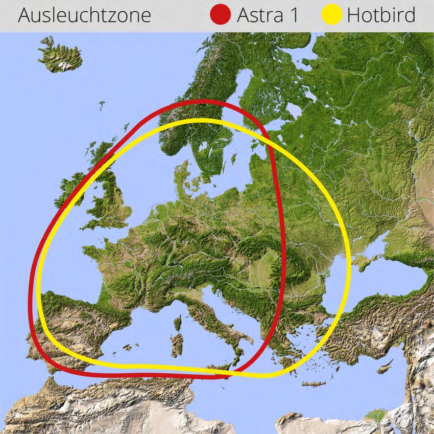
DEUTSCH 197. Ausleuchtzone
Astra 1 Hotbird
Hinweis:
In den Randgebieten der Ausleuchtzone kann es zu Empfangsstörungen
kommen.
20 DEUTSCH8. Montageabmessungen
Fahrtrichtung
Max. Schwenkbereich
Drehpunkt
46 cm
31 cm
31 cm
77 cm
DEUTSCH 219. Technische Details
Antennen-Typ Off-Set-Spiegel
1 (Caravanman Kompakt 3)
Anzahl der Teilnehmer
2 (Caravanman Kompakt 3 Twin)
LNB-Typ Universal-LNB
Frequenzband Ku-Band
Frequenzbereich 10.7 GHz bis 12.75 GHz
LNB-Verstärkung 33 dBi
Empfangsleistung 49 dBW
Polarisation Vertikal / Horizontal
Motorsteuerung 2-Achsen DC-Motor
Neigungswinkel 15° bis 62°
Suchwinkel 360°
Temperaturbereich -25° C bis +70° C
Spannungsversorgung 12 V DC @ 5 Amper
Abmessungen Spiegel 460 x 320 mm (B/H)
Abmessungen Antenne 460 x 170 x 460 mm (B/H/T)
Gewicht Antenne 5,1 kg
Abmessungen Steuergerät 195 x 30 x 150 mm (B/H/T)
Gewicht Steuergerät 360 g
Hinweis:
Gewicht und Abmessungen sind nicht die absolut exakten Werte. Technische
Daten können jederzeit und ohne vorherige Ankündigung geändert werden.
22 DEUTSCHKonformitätsinformation
Hiermit erklärt die Firma Megasat Werke GmbH, dass sich folgendes Gerät in
Übereinstimmung mit den grundlegenden Anforderungen und den übrigen
einschlägigen Bestimmungen der Richtlinien 2014/30/EU (EMV), 2014/35/EU
(LVD) und 2014/53/EU (RED) befindet:
Megasat Caravanman Kompakt 3 (Artikel-Nr. 1500192)
Megasat Caravanman Kompakt 3 Twin (Artikel-Nr. 1500193)
Die Konformitätserklärung zu diesen Produkt liegt der Firma vor:
Megasat Werke GmbH, Industriestraße 4a, D-97618 Niederlauer
Die Konformitätserklärung können Sie auf unserer Homepage downloaden:
www.megasat.tv/support/downloads
Notizen
DEUTSCH 23PRODUKTREGISTRIERUNG
Mit der Registrierung Ihres Megasat-Produkts haben Sie Zugriff auf
unsere automatischen E-Mail-Benachrichtigungen. Falls ihr Produkt
eine neue Firmware benötigt, werden Sie per E-Mail benachrichtigt.
Für die Registrierung besuchen Sie bitte unsere Homepage
www.megasat.tv
Das Formular finden Sie unter Support a Produktregistrierung
Version: 1.0 (August 2020)
Technische Änderungen, Druckfehler und Irrtümer vorbehalten.
Megasat Werke GmbH | Industriestraße 4a | D-97618 Niederlauer
www.megasat.tv | info@megasat.tvCaravanman Kompakt 3 user manual
Content

     1. Introduction
        1.1 Safety Information............................................................................... 03
        1.2 Delivery................................................................................................... 03
        1.3 System components............................................................................ 04

     2. Installation
        2.1 Installation on the roof....................................................................... 05
        2.2 Gluing instructions............................................................................... 06
        2.3 Indoor installation................................................................................ 07
        2.4 Connection of the components....................................................... 08
        2.5 The control unit.................................................................................... 10
        2.6 Satellite transmission.......................................................................... 11

     3. Satellite search with the control unit
        3.1 Designation of the respective LEDs and keys............................... 12
        3.2 Satellite search..................................................................................... 13

     4. Mobile app for controlling the antenna
        4.1 Connecting the control unit to the mobile device....................... 14
        4.2 Firmware update of the antenna..................................................... 16
        4.3 Change satellite.................................................................................... 17
        4.4 Disconnect Bluetooth® connection................................................. 17

     5. Troubleshooting........................................................................................ 18

     6. Setting values for the skew.................................................................. 19

     7. Footprint...................................................................................................... 20

     8. Mounting dimensions............................................................................. 21

     9. Specifications............................................................................................. 22

02                                                     ENGLISH
1. Introduction
1.1 Safety Information
Please read the user manual carefully before you start the installation.
If you have already installed similar products, the procedure may not be
the same as for this product.
Improper handling can cause serious damage to this device. Those respon-
sible may also be held responsible for any resulting further damage to the
equipment.
Please check the correct operating voltage of your power supply before com-
missioning. Please refer to the specifications in this user manual for the ope-
rating voltage of the device.
The control unit must not be exposed to dripping water, splashing water or
other liquids.
Do not let children play with foils or other packaging materials, there is a
danger of suffocation.
1.2 Delivery
1x Caravanman Kompakt 3
1x Control unit incl. powercable Optional accessories:
1x Coax cable (1 m) Mobile Kit 3
1x Coax cable (10 m) for mobile use
1x Roof lead-through
1x User manual
Art-No.: 1201000
ENGLISH 031. Introduction
1.3 System components
Open the carton and remove the control unit, connection cables and packing
material. Lift the antenna straight up out of the box. Never turn the system
upside down!
WARNING!
Never touch the antenna direc-
tly to the mirror when lifting it
out of the box. Lift the antenna
by the base plate.
Antenna unit
The high performance antenna and the elevation angle of 15-
62° allows the best possible reception in the most important
holiday destinations in Europe.
Control unit
The control unit is used for satellite selection and control. It is
connected between antenna and TV (receiver) and supplies the
antenna with power. After successful alignment the device can
be switched off.
Note:
The Caravanman Kompakt 3 Twin has an additional connection for a second
TV or receiver. For the correct connection of the components, please refer to
the connection diagram in this operating manual.
04 ENGLISH2. Installation
2.1 Installation on the roof
As a matter of principle, we recommend having the installation carried
out by your specialist dealer or a specialist workshop! Please also note
that the vehicle height changes accordingly due to the antenna! Please
strictly adhere to the individual points of the installation instructions!
General information
Provide a suitable workplace, a garage/hall is better than an outdoor place. The
ambient temperature for installation must be between +5° C and max. +25° C.
Do not work directly in the sun. Observe the work regulations when handling
chemical products. Ensure the necessary work hygiene.
Preparation
1. Make sure that the roof of your vehicle is sufficiently stable. If the roof sta-
bility is insufficient or doubtful, attach an approx. 2 mm thick sheet metal
plate measuring approx. 100 x 100 cm to the outer skin of the roof. Please
ask your vehicle manufacturer for more information.
2. Check that all parts are present.
3. Place the antenna on the later mounting
place and align it so that the mirror and
the LNB unit point towards the rear of
the vehicle. Ensure that the mounting
surface is level and that no roof struc-
tures are in the way. Always observe
the mounting dimensions in this user
manual. The minimum distance to an air
conditioning unit should be 30 cm.
4. Clean the mounting surface with a
suitable cleaner and a fleece cloth to
remove dirt and impurities. Then mark
the antenna base with a pen.
ENGLISH 052. Installation 5. Slightly roughen the drawn surfaces and feet with sandpaper (120 grain) and clean the surface again with the cleaner and allow the cleaner to flash off for about 10 minutes. WARNING: Do not touch the surfaces afterwards. 6. Mount the roof lead-through (preferably in the slipstream behind the an- tenna) on the vehicle roof. Make sure that the penetration of water and moisture (e.g. rain or splash water) into the drill hole is avoided. Make sure that the cables are not bent too much to avoid signal loss and damage to the cable (smallest bending radius max. 5-7 cm). 2.2 Gluing instructions 1. Prepare the adhesive for mounting. 2. Now apply the adhesive to the underside of the antenna base in serpentine lines so that the adhesive cures well all the way inside. 3. Now immediately (within 5 minutes after applying the adhesive) place the antenna on the marked field. Press the foot lightly and evenly and fix the antenna so that it does not slip, e.g. with adhesive tape. There must still be at least 2 mm of adhesive between the antenna foot and the surface after pressing on. The adhesive is cured after max. 48 hours at +18° C and a rela- tive humidity of 50%. If there is a low humidity during the installation period, spray some water into the air around the antenna after the adhesive has been applied. 4. Remove any leaked adhesive mass immediately with a spatula or similar and clean the soiled surfaces with the cleaner and a fleece cloth. 5. For safety reasons, you can additionally attach the antenna base. To do this, drill through the existing holes in the antenna base into the roof of your vehicle and fix it with a screw and lock nut. To prevent the freshly glued foot from slipping, wait until the adhesive has hardened. 6. After complete assembly and hardening of the adhesive, a silicone joint can be drawn around the antenna base. 06 ENGLISH
2. Installation
2.3 Indoor installation
1. The coax cable is laid inside the vehicle.
2. When choosing the location for the control unit and the satellite receiver,
make sure that both devices are in a dry and protected place.
3. Do not place the control unit and satellite receiver near heat sources and
ensure sufficient ventilation.
4. The basic connection options for the antenna system are shown below:
Connect the power supply (red-black cable) for the control unit to your
vehicle‘s battery via a fuse (7 amps) to prevent cable fire in the event of
a short circuit. The yellow cable is connected to the ignition plus of the
vehicle and is also protected by a 7 amp fuse (This cable only needs to
be connected if the antenna is to retract automatically when the engine
is started). The remaining black cable is connected to the corresponding
negative pole of the ignition system (ground).
Connect the coax cable from the antenna to the control unit
(10 m coax cable with F-plug in „ANTENNA“)
Connect the control unit to the TV or satellite receiver
(1 m coaxial cable with F-plug from „RECEIVER“ to the satellite receiver)
Note:
With the Caravanman Kompakt 3 Twin you connect a second coaxial cable
from the antenna directly to the second TV or satellite receiver.
ENGLISH 072. Installation
2.4 Connection of the components
Ignition plus
The antenna automatically moves to the retracted position as soon as the ig-
nition key is turned. This function is only guaranteed if the control unit is swit-
ched on and cables 4 and 5 are connected to the ignition plus of the vehicle.
Power supply
DC 12 V via battery (positive pole permanent supply RED) or optional 230 V / 12 V
DC power supply (no chargers). Make sure that a current of at least 5 amperes
is guaranteed.
1 Coax cable 10 m
2 Coax cable 1 m
3 Positive pole
4 Negative pole
5 Ignition plus
Warning: Always connect the control unit via a 7 ampere fused cable
of at least 2.5 mm² thickness. Never connect to the car battery without
a fuse.
08 ENGLISH2. Installation
Television 2
Control-Box
Receiver
Second connection only for
Caravanman Kompakt 3 Twin.
Coaxial cable NOT included!
1 2
Television 1
(–) (+)
ANT
STB
4
5
4
Control unit 3
(+) (–)
ENGLISH 092. Installation
2.5 Control unit
Standby Current satellite Satellite selection Confirmation
Status LEDs Home position
(retracts antenna)
Connection Connection for external
for antenna power supply (optional)
Connection to Power supply
TV / set-top box (12 Volt)
Warning: Always connect the control unit via a 7 ampere fused cable
of at least 2.5 mm² thickness. Never connect to the car battery without
a fuse.
10 ENGLISH2. Installation
2.6 Satellite broadcasting
Direct Broadcast Service (DBS) satellites broadcast audio, video and data infor-
mation from satellites located 22.000 miles in space. A receiving station, such as
the antenna, should include a dish and satellite receiver to receive the signals
and process them for use by the consumer audio and video equipment. The
system requires a clear view of the satellite to maximize the signal reception.
Good reception signal Bad reception signal
Objects such as tall lighthouse, bridges and big ship that block this view will
cause a loss of signal. The signal will be quickly restored once the antenna has
a clear line of sight again. Heavy rain, cloud, snow or ice may also interfere
with the signal reception quality. If the satellite signal is lost due to blockage
or severe weather condition, services from the receiver will be lost (picture will
freeze frame and may disappear). When the satellite signal strength is again
high enough, then the receiver will resume providing desired programming
services.
ENGLISH 113. Satellite search with the control unit
3.1 Designation of the respective LEDs and keys
Search-LED Satellite-LED
Flashing during satellite search AS4 Astra 4 (4° East)
Reception-LED Satellite-LED
Lights up when a satellite is found HOT Hotbird (13° East)
Error-LED Satellite-LED
Lights up in case of a malfunction HIS Hispasat (30° West)
Bluetooth-LED Satellite-LED
Lights when connected E9E Eutelsat 9 B (9° East)
Satellite-LED Satellite-LED
AS1 Astra 1 (19,2° East) E5W Eutelsat 5 West (5° West)
Satellite-LED Satellite-LED
AS2 Astra 2 (28,2° East) TUR Turksat (42° East)
Satellite-LED Satellite-LED
AS3 Astra 3 (23,5° East) THOR Thor (0,8° West)
Standby-button OK-button
Switches the control unit on / off Confirms the satellite selection
Arrow-button STOW-button
Changing satellites Moves the antenna to the home position
12 ENGLISH3. Satellite search with the control unit
3.2 Satellite search
1. Switch the control unit on at the standby button.
2. The search LED flashes green during the search process.
3. The satellite LED of the last used satellite flashes green.
To change the satellite, you must change the satellite with the arrow
4. keys within approx. 3-5 seconds while the LEDs are flashing. Later
changing is only possible if the antenna has found a satellite before.
Confirm the satellite selection with the OK button or wait 3-5 se-
5.
conds until the satellite logs in automatically.
After the selected satellite has been found, the reception LED will
6.
light up orange.
7. If the selected satellite was not found, the Error LED will light red.
After successful search, you can switch off the control unit again at
8.
the standby key.
Note:
If you want to start the search at another location, simply press the Standby
key to search for the last selected satellite.
Retract the antenna to the home position
1. If necessary, switch the control unit on at the standby button.
2. Press the STOW button to retract the antenna.
ENGLISH 134. Mobile App to control the antenna
With the app, the satellites can be changed via the smartpho-
ne or tablet. Future firmware updates for the control unit can
also be made. The app is available free of charge from the App
Store (iOS) or the Google Play Store (Android). Search for the
name „Megasat“ in the respective store.
Note: Make sure that Bluetooth® is activated on the mobile device and that
you are no further than 10 metres away from the control unit.
4.1 Connecting the control unit to the mobile device
1. After the app has opened, the 2. Now switch on the control unit.
following start screen appears. The name of the control unit will
then appear in the selection menu.
Click on it.
14 ENGLISH4. Mobile App to control the antenna
3. On the main interface of the app there are now various options:
Firmware update of the antenna
CARAVANMAN KOMPAKT 3
Change satellites
Disconnect Bluetooth® connection
ENGLISH 154. Mobile App to control the antenna
4.2 Firmware Update of the Antenna
1. Tap the button to open the up-
date menu.
CARAVANMAN KOMPAKT 3
2. The app checks whether a newer
version of the firmware is currently
available:
Reading data from server...
CARAVANMAN KOMPAKT 3
3. If no new firmware is available, the
current version number is dis-
played and the following message
appears:
Latest version already updated
CARAVANMAN KOMPAKT 3
4. If a new firmware is available, the
new version number is displayed
and the following message appears:
New software available
Then tap the „Upload“ button to
update the antenna.
CARAVANMAN KOMPAKT 3
16 ENGLISH4. Mobile App to control the antenna
4.3 Change satellite
1. Tap on the button to open the
satellite list.
2. Select the desired satellite. After
approx. 3-5 seconds the satellite
will be searched automatically.
AS1 Astra 1 (19,2° East)
AS2 Astra 2 (28,2° East)
AS3 Astra 3 (23,5° East)
AS4 Astra 4 (4° East)
HOT Hotbird (13° East)
HIS Hispasat (30° West)
E9E Eutelsat 9 B (9° East)
E5W Eutelsat 5 West (5° West)
TUR Türksat (42° East)
THO Thor (0,8° West)
Note:
A satellite change is only possible
if the antenna has found a satellite
before.
4.4 Disconnect Bluetooth® connection
Tap the button to disconnect the
Bluetooth® connection between
mobile device and control unit.
ENGLISH 175. Troubleshooting No satellite signal Objects such as trees, bridges and large houses located at the satellite‘s angle of incidence cause the signal to be lost. If the satellite signal is lost due to severe weather conditions, the current program of the TV or receiver will be interrup- ted (the picture will pixelate, freeze or disappear). When the weather conditions allow good reception again, the TV picture will be restored. Is there dirt on the antenna? Heavy dirt on the housing can cause reception problems. Is everything correctly connected and switched on? Make sure that the TV and the receiver are connected correctly and that the receiver is correctly set for satellite reception. Are all cables connected correc- tly and the connections screwed tightly onto the coaxial cable? Also check the coaxial cable for kinks. Footprint of the satellite Satellites are in fixed positions above the equator in orbit. In order to receive the TV signals, the receiving location must be within the footprint. Use the diagram to check whether your location is within the satellite‘s footprint. In the peripheral areas of the footprint, reception interference may occur. Satellite frequency of a TV channel was changed TV stations change their frequency sporadically, which then no longer matches the frequency in the receiver. Ask for the current frequency of the channel. The firmware of the control unit is outdated If transponders on the satellite are changed, the antenna may no longer be able to find the satellite. Update the firmware of the control unit to get the latest transponder information. The mobil app does not connect to the control unit Make sure that Bluetooth® on your mobile device is switched on and that you are in the direct vicinity of the control unit (max. 10 metres). 18 ENGLISH
6. Einstellwerte für den Skew

 Skew-Einstellungswerte für europäische Hauptstädte

Signale in vertikaler (rot) und horizontaler
(blau) Linie haben einen Versatz von genau
                                                                                 0°
90° zueinander. Durch die unterschiedli-
che Position der Satelliten, abhängig von
Ihrem Standort, ist es möglich, dass die Sig-
nale nicht genau vertikal und horizontal auf
den LNB treffen. Um dieses anzupassen,
                                                                    +90°                     -90°
müssen Sie den LNB in die richtige Lage zu
dem ausgesendeten Signal bringen. Diese
Anpassung am LNB wird als „Skew-Einstel-
lung“ bezeichnet. Die folgende Abbildung
zeigt Ihnen die optimale Einstellung des
LNBs. Je genauer die Übereinstimmung,
desto besser der Empfang.

                                                                                      LNB position

      bad                    good                            best
                                                                                  Satellite signal
   reception               reception                      reception

Country       City         Astra 2   Astra 3    Astra 1   Hotbird   Astra 4   Thor      Hispasat   Eutelsat 5
Bulgaria      Sofia         +1.7      +6.8       +11.4     +11.0     +19.0    +24.0      +41.0       +27.2
Denmark       Copenhagen     -3.4      -0.4       +2.5      -0.3      +5.3     +9.1      +24.8       +11.6
Finland       Helsinki       +5.2      +7.9      +10.3      +6.8     +11.2    +14.2      +25.2       +16.0
France        Paris         -13.9     -10.5       -7.2      -9.2      -2.2     +2.9      +25.0       +6.3
Germany       Berlin         -4.1      -0.7       +2.6      +0.3      +6.6    +10.8      +27.8       +13.5
England       London        -13.7     -10.7       -7.8     -10.3      -4.0    +0.6       +21.6       +3.9
Greece        Athens        +1.3      +7.3       +12.7     +13.4     +22.5    +28.1      +45.9       +31.6
Hungary       Budapest       -1.3     +3.0        +6.9      +5.6     +12.8    +17.5      +34.7       +20.5
Italy         Rome           -9.8      -5.0       -0.4      -0.6      +8.5    +14.6      +37.0       +18.5
Poland        Warsaw         +1.5      +5.1       +8.4      +6.1     +12.2    +16.2      +31.0       +18.8
Portugal      Lisbon        -30.2     -27.0      -23.7     -25.3     -16.8    -10.1      +23.9        -5.1
Spain         Madrid        -24.8     -21.2      -17.6     -18.7      -9.9     -3.2      +27.5        +1.5
Belgium       Brussels      -11.2      -7.9       -4.8      -7.0      -0.3     +4.4      +24.7        +9.3
Sweden        Stockholm      +1.1      +3.8       +6.4      +3.0      +7.8    +11.0      +23.8       +13.0
Switzerland   Bern          -11.3      -7.5       -3.8      -5.2      +2.4     +7.8      +29.5       +11.4
Austria       Vienna         -3.4      +0.7       +4.5      +3.0     +10.2    +15.0      +32.9       +18.0

                                               ENGLISH                                                   19
7. Footprint
Astra 1 Hotbird
Note:
In the outlying areas of the footprint there may be interference.
20 ENGLISH8. Mounting dimensions
Direction of travel
Max. pivoting range
Pivot point
46 cm
31 cm
31 cm
77 cm
ENGLISH 217. Specifications
Antenna type Off-Set-dish
1 (Caravanman Kompakt 3)
Number of user
2 (Caravanman Kompakt 3 Twin)
LNB type Universal-LNB
Frequency band Ku-Band
Frequency range 10.7 GHz to 12.75 GHz
LNB Reinforcement 33 dBi
Reception performance 49 dBW
Polarization Vertikal / Horizontal
Motor control unit 2-axis DC-motor
Tilt angle 15° to 62°
Search angle 360°
Temperature range -25° C to +70° C
Power supply 12 V DC @ 5 Ampere
Dish dimensions 460 x 320 mm (B/H)
Antenna dimensions 460 x 170 x 460 mm (B/H/T)
Weight antenna 5,1 kg
Control unit dimensions 195 x 30 x 150 mm (B/H/T)
Weight control unit 360 g
Note:
Weight and dimensions are not absolutely exact values.
Technical details can be changed at any time without prior notice.
22 ENGLISHConformity information
Hereby, Megasat Werke GmbH declares that the following product is in com-
pliance with the essential requirements and other relevant provisions of direc-
tives 2014/30/EU (EMC), 2014/35/EU (LVD) and 2014/53/EU (RED):
Megasat Caravanman Kompakt 3 (Artikel-No. 1500192)
Megasat Caravanman Kompakt 3 Twin (Artikel-No. 1500193)
The declaration of conformity for this product is located at the company:
Megasat Werke GmbH, Industriestraße 4a, D-97618 Niederlauer
The declaration of conformity can be downloaded from our homepage:
www.megasat.tv/support/downloads
Notes
ENGLISH 23PRODUCT REGISTRATION
Registering your Megasat product gives you access to our automatic
e-mail notifications. If your product requires new firmware, you will
be notified by e-mail.
To register, please visit our homepage www.megasat.tv
You can find the form under Support a Product registration
Version: 1.0 (August 2020)
Technical changes, misprint and errors reserved.
Megasat Werke GmbH | Industriestraße 4a | D-97618 Niederlauer
www.megasat.tv | info@megasat.tvCaravanman Kompakt 3 Mode d’emploi
Sommaire

     1. Introduction
        1.1 Consignes de sécurité......................................................................... 03
        1.2 Volume de livraison............................................................................. 03
        1.3 Composants de système.................................................................... 04

     2. Installation
        2.1 Installation sur le toit........................................................................... 05
        2.2 Instructions de collage........................................................................ 06
        2.3 Installation à l‘intérieur....................................................................... 07
        2.4 Connexion des composants.............................................................. 08
        2.5 L‘unité de contrôle............................................................................... 10
        2.6 Transmission par satellite.................................................................. 11

     3. Recherche de satellites avec l‘unité de contrôle
        3.1 Désignation des LEDs et des clés respectives.............................. 12
        3.2 Recherche par satellite....................................................................... 13

     4. Application mobile pour contrôler l‘antenne
        4.1 Connexion de l‘unité de commande à l‘appareil mobile............ 10
        4.2 Mise à jour du micrologiciel de l‘antenne...................................... 12
        4.3 Changer de satellite............................................................................. 13
        4.4 Déconnexion de Bluetooth®............................................................. 13

     5. Dépannage.................................................................................................. 18

     6. Fixer des valeurs pour le biais............................................................. 19

     7. Zone de couverture................................................................................. 20

     8. Dimensions de montage........................................................................ 21

     9. Spécifications techniques..................................................................... 22

02                                                   FRANÇAIS
1. Introduction
1.1 Consignes de sécurité
Veuillez lire attentivement le manuel d‘utilisation avant de commencer
l‘installation. Si vous avez déjà installé des produits similaires, la procé-
dure peut ne pas être la même que pour ce produit.
Une mauvaise manipulation peut causer de sérieux dommages à cet appa-
reil. Les responsables peuvent également être tenus pour responsables de
tout dommage supplémentaire qui pourrait en résulter pour l‘équipement.
Veuillez vérifier la tension de fonctionnement correcte de votre alimentation
électrique avant la mise en service. Pour la tension de fonctionnement de l‘ap-
pareil, veuillez vous référer aux données techniques de ce mode d‘emploi.
L‘unité de commande ne doit pas être exposée à des gouttes d‘eau, des
éclaboussures d‘eau ou d‘autres liquides.
Ne laissez pas les enfants jouer avec des feuilles ou d‘autres matériaux d‘em-
ballage, il y a danger de suffocation.
1.2 Volume de livraison
1x Caravanman Kompakt 3
1x Appareil de commande Optionales Zubehör:
(câble électrique inclus) Mobil-Kit 3 pour
1x Câble coaxial (1 m) une utilisation mobile
2x Câble coaxial (10 m)
1x Traversée de toit
1x Mode d‘emploi
Numéro d’article: 1201000
FRANÇAIS 031. Introduction
1.3 Composants du système
Ouvrez le carton et retirez l‘unité de commande, les câbles de connexion et le
matériel d‘emballage. Soulevez l‘antenne pour la sortir de sa boîte. Ne mettez
jamais le système sens dessus dessous !
ATTENTION!
Ne touchez jamais l‘antenne
directement au miroir lorsque
vous la sortez de la boîte. Sou-
levez l‘antenne par la plaque de
base.
Unité d‘antenne
L‘antenne haute performance et l‘angle d‘élévation de 15-62°
permettent la meilleure réception possible dans les plus im-
portantes destinations de vacances en Europe.
Unité de contrôle
L‘unité de contrôle est utilisée pour la sélection et le contrô-
le des satellites. Il est connecté entre l‘antenne et le téléviseur
(récepteur) et alimente l‘antenne en énergie. Après un aligne-
ment réussi, l‘appareil peut être éteint.
Remarque:
Le Caravanman Kompakt 3 Twin dispose d‘une connexion supplémentaire
pour un second téléviseur ou récepteur. Pour le branchement correct des
composants, veuillez vous référer au schéma de connexion de ce manuel
d‘utilisation.
04 FRANÇAIS2. Installation
2.1 Installation sur le toit
Par principe, nous recommandons de faire effectuer l‘installation par
votre revendeur spécialisé ou un atelier spécialisé ! Veuillez également
noter que la hauteur du véhicule change en conséquence à cause de
l‘antenne ! Veuillez respecter scrupuleusement les différents points
des instructions d‘installation !
Informations générales
Prévoyez un lieu de travail approprié, un garage/hall est préférable à un lieu
extérieur. La température ambiante pour l‘installation doit être comprise entre
+5° C et +25° C au maximum. Ne pas travailler directement au soleil. Respec-
tez les règles de travail lorsque vous manipulez des produits chimiques. Assu-
rer l‘hygiène nécessaire au travail.
Préparation
1. Assurez-vous que le toit de votre véhicule est suffisamment stable. Si la
stabilité du toit est insuffisante ou douteuse, fixez une plaque de tôle d‘en-
viron 2 mm d‘épaisseur mesurant environ 100 x 100 cm sur le revêtement
extérieur du toit. Veuillez vous adresser au constructeur de votre véhicule
pour plus d‘informations.
2. Vérifiez que toutes les pièces sont pré-
sentes.
3. Placez l‘antenne sur le dernier empla-
cement de montage et alignez-la de
manière à ce que le miroir et l‘unité LNB
soient dirigés vers l‘arrière du véhicule.
Assurez-vous que la surface de montage
est plane et qu‘aucune structure de toit
ne gêne. Il est essentiel de respecter les
dimensions de montage indiquées dans
ces instructions. La distance minimale par
rapport à un appareil de climatisation doit
être de 30 cm.
4. Nettoyez la surface de montage avec un
produit nettoyant approprié et un chif-
fon molletonné pour enlever la saleté et
les impuretés. Ensuite, marquez la base
de l‘antenne avec un stylo.
FRANÇAIS 052. Installation 5. Rendre légèrement rugueux les surfaces et les pieds dessinés avec du pa- pier de verre (grain 120) et nettoyer à nouveau la surface avec le nettoyant et laisser le nettoyant s‘éteindre pendant environ 10 minutes. ATTENTION: Ne pas toucher les surfaces par la suite. 6. Montez le passage de toit (de préférence dans le couloir de saut derrière l‘antenne) sur le toit du véhicule. Veillez à éviter la pénétration de l‘eau et de l‘humidité (par exemple, la pluie ou les éclaboussures d‘eau) dans le trou de forage. Veillez à ce que les câbles ne soient pas trop pliés pour éviter la perte de signal et l‘endommagement du câble (plus petit rayon de courbure max. 5-7 cm). 2.2 Instructions de collage 1. Préparez l‘adhésif pour le montage. 2. Appliquez maintenant l‘adhésif sur la face inférieure de la base de l‘antenne en lignes serpentines afin que l‘adhésif puisse bien durcir jusqu‘à l‘intérieur. 3. Maintenant, immédiatement (dans les 5 minutes suivant l‘application de l‘adhésif), placez l‘antenne sur le champ marqué. Appuyez légèrement et régulièrement sur le pied et fixez l‘antenne de manière à ce qu‘elle ne glisse pas, par exemple avec du ruban adhésif. Il doit rester au moins 2 mm de colle entre le pied de l‘antenne et la surface après avoir appuyé dessus. L‘ad- hésif est durci après 48 heures maximum à +18° C et une humidité relative de 50%. Si l‘humidité est faible pendant la période d‘installation, vaporisez un peu d‘eau dans l‘air autour de l‘antenne après avoir appliqué l‘adhésif. 4. Enlevez immédiatement toute masse adhésive qui a fui à l‘aide d‘une spatu- le ou autre et nettoyez les surfaces souillées avec le nettoyant et un chiffon molletonné. 5. Pour des raisons de sécurité, vous pouvez également fixer le socle de l‘an- tenne. Pour ce faire, percez les trous existants dans la base de l‘antenne dans le toit de votre véhicule et fixez-la avec une vis et un écrou de blocage. Pour éviter que le pied fraîchement collé ne glisse, attendez que la colle ait durci. 6. Après l‘assemblage complet et le durcissement de l‘adhésif, un joint en sili- cone peut être tiré autour de la base de l‘antenne. 06 FRANÇAIS
Sie können auch lesen