Betriebsvorschrift für Sicherheitsventile Operating Instructions for Safety Valves - SVU 446, 448
←
→
Transkription von Seiteninhalten
Wenn Ihr Browser die Seite nicht korrekt rendert, bitte, lesen Sie den Inhalt der Seite unten
Betriebsvorschrift für Sicherheitsventile
Operating Instructions for Safety Valves
  SVU 446, 448
2 ∙        Betriebsvorschriften / Operating Instructions

Sicherheitsventile / Safety Valves
Inhalt

                                                                                                                            The information contained in this brochure merely serves as a non-binding description of our products and is without guarantee. Binding information, in particular relating to capacity data and suitability for specific applications, can only be provided within the framework of concrete
Content
  Kapitel                                                  Seite       Chapter                                       Page

      1.       Übersicht der Bauarten                      3              1.     Overview of Types                   3

      2.       Technische Kennwerte                        3              2.     Technical Characteristics           3

      3.       Sicherheitshinweise                         4              3.     Safety Advices                      4

      4.       Anwendung                                   5              4.     Application                         5

      5.       Funktionsbeschreibung                       6              5.     Functional Description              6

      6.       Einbau                                      6              6.     Installation                        6

      7.       Wartung                                     6              7.     Maintenance                         6

      8.       Transport und Lagerung                      9              8.     Transport and Storage               9

      9.       Garantie                                    9              9.     Warranty                            9

   10.         Ersatzteilliste                             9              10. Spare Parts List                       9

   11.         Kennzeichnung                               10             11. Labelling                              10

   12.         Hinweis auf Restgefahren                    10             12. Advices on Residual Hazards            10

                                                                                                                            inquiries. Printed on chlorine-free bleached paper · Printed in Germany · Subject to modification

GEA Germany
GEA AWP GmbH
Armaturenstr. 2                                 Tel +49 3984 8559-0                             info@awpvalves.com
17291 Prenzlau, Germany                         Fax +49 3984 8559-18                            awpvalves.com
3 ∙ Betriebsvorschriften / Operating Instructions
Sicherheitsventile / Safety Valves
Übersicht der Bauarten, Technische Kennwerte
The information contained in this brochure merely serves as a non-binding description of our products and is without guarantee. Binding information, in particular relating to capacity data and suitability for specific applications, can only be provided within the framework of concrete
Overview of Types, Technical Characteristics
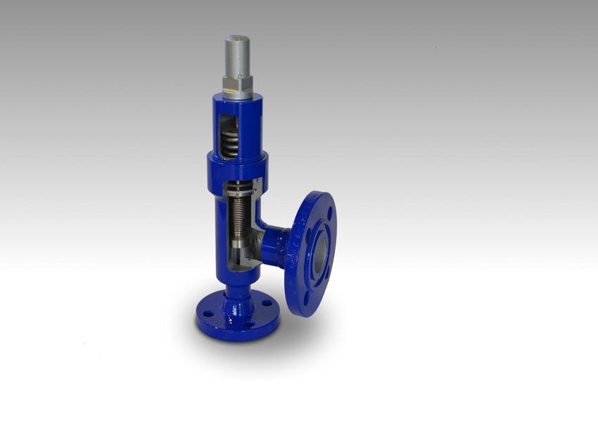
1. Übersicht der Bauarten (DN 8 – DN 15) 1. Overview of Types (DN 8 – DN 15)
SVU 446 / 448…0… Anschweißenden SVU 446 / 448…0… butt welding ends
SVU 446 / 448…1… Flanschenden SVU 446 / 448…1… flanged ends
SVU 446 / 448…4… Schraubenden SVU 446 / 448…4… threaded ends
SVU 446 / 448…B… Lötenden SVU 446 / 448…B… brazed ends
Druckfeder
pressure spring
O-Ring D
o-ring sealing D
PTFE-Ring
PTFE sealing
DN 2
O-Ring S
o-ring sealing S inquiries. Printed on chlorine-free bleached paper · Printed in Germany · Subject to modification
DN 1
2. Technische Kennwerte 2. Technical Characteristics
Gehäusewerkstoff – Auswahl nach DIN EN12284, Selection of body material as per German DIN
AD-2000 Reihe W EN12284, AD-2000 series W
Edelstahl (NIRO): X5CrNi18-10 1.4301 Stainless steel (NIRO): X5CrNi18-10 1.4301
X6CrNiTi18-10 1.4541 X6CrNiTi18-10 1.4541
oder gleichwertige or any equivalent
GEA Germany
GEA AWP GmbH
Armaturenstr. 2 Tel +49 3984 8559-0 info@awpvalves.com
17291 Prenzlau, Germany Fax +49 3984 8559-18 awpvalves.com4 ∙ Betriebsvorschriften / Operating Instructions
Sicherheitsventile / Safety Valves
Technische Kennwerte, Sicherheitshinweise
The information contained in this brochure merely serves as a non-binding description of our products and is without guarantee. Binding information, in particular relating to capacity data and suitability for specific applications, can only be provided within the framework of concrete
Technical Characteristics, Safety Advices
SVU 448 SVU 446
PN DN TB (MWT) [°C] -60 -10 +50 +180 -50 -10 +50 +110
40 8-15 30 40 40 40 30 40 40 40
PS (MWP) [bar]
63 8-15 47,25 63 63 63 47,25 63 63 63
Zulässiger Umgebungstemperaturbereich (C°): Permissible ambient temperature range (C°)
-35 bis +55 -35 to +55
Betriebsmedien Working Media
Kältemittel EN 378 Teil 1, z.B.NH3, R22, R134a, R290 Refrigerant EN 378 part 1, e.g. NH3, R22, R134a,
(Propan), R507, Gemische mit Kältemaschinenöl, R290 (propane), R507, mixtures with refrigerator oil,
neutrale, gasförmige und flüssige Medien Kühlsole auf neutral, gaseous and liquid media, cold brine basing
Glycol-Basis on glycol
Kennwerte Characteristics
zuerkannte Ausflussziffer
DN1/DN2 8/10 10/10 15/15
certified coefficient of discharge
für Dampf/Gas
Kdr (αw) [-] 0,57 0,57 0,57
for steam/gas
für Flüssigkeit
Kdr (αw) [-] - - -
for liquid
engster Strömungsquerschnitt
[mm2] 78 78 78
smallest cross section of flow
Einstelldruck
pe [bar] 5–63 5–63 5–63
set pressure
Druckbereich der Federn siehe Ersatzteilliste. For pressure range of the springs see spare parts list.
Einbaulage: senkrecht nach AD2000-Merkblatt A2, Mounting position: vertical according to AD2000-
waagerecht leaflet A2, and horizontal
Leckage nach außen:5 ∙ Betriebsvorschriften / Operating Instructions
Sicherheitsventile / Safety Valves
Sicherheitshinweise, Anwendung
The information contained in this brochure merely serves as a non-binding description of our products and is without guarantee. Binding information, in particular relating to capacity data and suitability for specific applications, can only be provided within the framework of concrete
Safety Advices, Application
Gesamtanlage kann für sich geerdet werden oder in own or included into the potential equalization of the
den Potentialausgleich des Gebäudes eingebunden building. The operator has to check the potential
werden. Der Potentialausgleich ist vom Betreiber in equalization in regular intervals.
regelmäßigen Abständen zu überprüfen. Outlets to safety devices should not front other branch
Abgänge zu Sicherheitseinrichtungen sollten nicht points.
anderen Abzweigungen gegenüber liegen. Safety valves must be protected against damaging
Sicherheitsventile sind gegen schädigende äußere influences from outside (e. g. climatic influences)
Einflüsse (z. B. Witterungseinflüsse), die which might impair their functionality.
funktionshemmend sein können, zu schützen. Safety valves made of unalloyed body parts must be
Sicherheitsventile aus unlegierten Gehäuseteilen sind permanently protected against corrosion.
dauerhaft gegen Korrosionsbildung zu schützen. Transferring vibrations to the safety valve has to be
Übertragungen von Vibrationen auf das avoided.
Sicherheitsventil sind zu vermeiden. Discharge pipes must be dimensioned and installed in
Abblaseleitungen müssen, unter Berücksichtigung der a way to securely absorb the static dynamic reaction
örtlichen Betriebsverhältnisse, so bemessen und forces as well as the thermic stresses. The local
verlegt sein, dass die statischen dynamischen operating conditions have to be considered. Safety
Reaktionskräfte sowie die thermischen devices that are subject to discharging incendive
Beanspruchungen sicher aufgenommen werden media and therefore constitute a direct or indirect
können. An Sicherheitseinrichtungen, bei denen durch hazard to persons and ignition sources in their
das Austreten eines zündfähigen Mediums direkt oder environment must be appropriately protected (e. g.
indirekt Gefahren für die Personen oder die in der discharging into a safe environment).
Umgebung befindlichen Zündquellen entstehen, The recommended steps to limit potential explosions,
müssen geeignete Schutzmaßnahmen getroffen resp. the recommendations for wearing personal
werden (z.B. Abblasen in eine sichere Umgebung). protection equipment have to be attended and
Die empfohlenen Explosionsbegrenzungsmaßnahmen followed mandatorily when screw connections are
bzw. die Empfehlungen für das Tragen der being loosened or the pressure spring is being
persönlichen Schutzausrüstung im Sinne der Produkt- slackened.
Sicherheitsdatenblätter sind zwingend beim Lösen von Safety devices may be exclusively maintained by the
Verschraubungen oder Entspannen der Druckfeder zu manufacturer.
beachten und einzuhalten. Safety devices may only be replaced when the plant
Instandsetzungsmaßnahmen an den and its pipes are secured and depressurized. When
Sicherheitseinrichtungen dürfen ausschließlich nur inflammable gases such as propane, butane, methane
durch den Gerätehersteller durchgeführt werden. are being used this has to be done with tools that do
Ein Wechsel der Sicherheitseinrichtung darf nur im not create sparks.
gesicherten drucklosen Zustand der Anlage und deren When ammonia is being used as refrigerant, special
Leitungen durchgeführt werden. Bei brennbaren safety instructions have to be followed (see safety data
Gasen wie z.B. Propan, Butan, Methan, etc., ist sheet).
funkenarmes Werkzeug hierzu zu verwenden. After the safety valve has been installed a leakage test
Bei der Verwendung von Ammoniak als Kältemittel has to be performed by an authorized person.
sind besondere Sicherheitsmaßnahmen zu beachten The response pressure has to be checked in regular
(siehe auch Sicherheitsdatenblatt). intervals according to the setting certificate.
Nach der Installation der Sicherheitsarmatur ist ein
Dichtheitstest durch eine befähigte Person
durchzuführen. Die Überprüfung des Ansprechdruckes inquiries. Printed on chlorine-free bleached paper · Printed in Germany · Subject to modification
ist in regelmäßigen Abständen anhand der
Einstellbescheinigung vorzunehmen.
4. Anwendung 4. Application
AWP Normal-Sicherheitsventile sind geeignet für den AWP standard safety valves are suitable for being
Einsatz in Kältemittelkreisläufen für Industrie- Kälte- employed as relief valves in the refrigerant cycles of
anlagen als Abblaseventile. industrial refrigerating plants.
Normal- Sicherheitsventile sind Sicherheitseinrich- Standard safety valves are safety devices for
tungen zum Schutz der Kälteanlage oder ihrer Bauteile protecting the refrigerating plant or its components
vor unzulässiger Druckbeanspruchung (siehe auch from excess pressure (see also DIN 8975 part 7).
DIN 8975 Teil 7). They comply with the technical regulations of the
Sie entsprechen den Ausrüstungsvorschriften der German Technical Control Board (TÜV).
Technischen Überwachungsvereine (TÜV).
GEA Germany
GEA AWP GmbH
Armaturenstr. 2 Tel +49 3984 8559-0 info@awpvalves.com
17291 Prenzlau, Germany Fax +49 3984 8559-18 awpvalves.com6 ∙ Betriebsvorschriften / Operating Instructions
Sicherheitsventile / Safety Valves
Funktionsbeschreibung, Einbau, Wartung
The information contained in this brochure merely serves as a non-binding description of our products and is without guarantee. Binding information, in particular relating to capacity data and suitability for specific applications, can only be provided within the framework of concrete
Functional Description, Installation, Maintenance
5. Funktionsbeschreibung 5. Functional Description
AWP-Normal-Sicherheitsventile öffnen nach dem Once an AWP standard safety valve has responded, it
Ansprechen innerhalb von 10% Drucksteigerung bis opens within a pressure increasing range of 10 % until
zum konstruktiv begrenzten Hub. it reaches the constructional limit. They close within a
Sie schließen innerhalb einer Druckabsenkung von pressure dropping range of 10 % below the set
10% unter dem Ansprechpunkt. response pressure.
Die Ventile öffnen unabhängig vom Gegendruck! The valves open independent of back pressure!
! Ansprechdruck = Einstelldruck! ! response pressure = set pressure!
Zur Gewährleistung des Kdr -Wertes darf der The back pressure [abs.] may not exceed the value of
Gegendruck [abs.] max. 25% des Ansprechdruckes 25% of the set pressure [abs.] in order to ensure the
[abs.] betragen. Kdr -value.
6. Einbau 6. Installation
Vor Einbau der Ventile sind Rohrleitungen und Before installing the valves, the pipelines and the
Anlagenteile zu säubern. components have to be cleaned.
Bitte beachten! Please note!
Die Abweichung von der Parallelität bzw. The welding or flanged ends on the pipes that the
Rechtwinkligkeit der Anschweißenden bzw. valves are connected to have to be parallel, resp.
Flanschdichtflächen darf 1° nicht überschreiten. rectangular. If there is a deviation it may not exceed
Anschlußflansche müssen achsengleich sein. 1°. The connecting flanges have to be coaxial.
Ventile mit Transport- und Lagerschäden dürfen nicht Valves that have been damaged during transport or
eingebaut werden. storage may not be installed.
Nach dem Entfernen der Rohrstopfen können die After the protective caps have been removed, the
Ventile eingeschweißt bzw. montiert werden. valves can be welded, resp. installed.
Die Durchflußrichtung (siehe Pfeil auf Kenn- The flow direction (see arrow on name plate) has
zeichenschild) ist einzuhalten. to be observed.
Bei Anwendung moderner Schweißverfahren When modern welding processes are used (such as
(z. B. WIG, CO2) werden die Ventile zum TIG, CO2-shielded metal-arc) the valves do not have
Einschweißen nicht demontiert. to be disassembled for welding.
Die Befestigungsschrauben und Muttern der Flansche The fastening bolts and nuts have to be tightened
sind über Kreuz und gleichmäßig anzuziehen. crosswise and evenly.
Beim Abblasen in die Atmosphäre sind die The pipes for blowing off the pressure into the
Abblasrohre möglichst kurz zu halten und dürfen keine atmosphere should be as short as possible and may
scharfen Krümmer aufweisen. Der Biegeradius muss not have any sharp bends. The bending radius must
mindestens 3 x RAØ (Rohraußendurchmesser) be at least 3 x RAØ (outside diameter of the pipe).
betragen. When filling oil or water into the recipient make sure
Beim Füllen der Öl- bzw. Wasservorlage ist darauf zu that no water or oil gets into the safety valves.
achten, dass kein Öl bzw. Wasser in die Normal- Installing locking devices before or behind safety
Sicherheitsventile gelangt. valves is not permitted, except 3-way valves (For
Absperreinrichtungen vor und hinter dem exceptions see DIN8975, part 7, article 8).
Sicherheitsventil sind unzulässig, ausgenommen inquiries. Printed on chlorine-free bleached paper · Printed in Germany · Subject to modification
To disassemble the valve cover / bonnet enough
Wechselventile (Ausnahmen siehe DIN8975, Teil 7, space has to be provided on the side of the cover /
Punkt 8). bonnet (approx. 50 mm)
Zur Demontage des Deckels / der Haube ist genügend
Platz auf der Deckel- / Haubenseite vorzusehen (ca.
50 mm).
7. Wartung 7. Maintenance
AWP Normal-Sicherheitsventile arbeiten wartungsfrei. AWP standard safety valves are maintenance-free.
Treten Mängel im Funktionsverhalten auf ist eine In case any defects in the functional performance of
Reparatur möglich. Während der Garantiezeit dürfen the valves occur, they can be repaired. During the
Reparaturen nur durch AWP bzw. – mit Einverständ- term of warranty, repairs may only be carried out by
nis von AWP – durch geschultes Instandhaltungs- AWP or – with AWP’s consent – by specially-trained
personal des Betreibers der Anlage vorgenommen maintenance personnel working for the plant operator.
werden.
GEA Germany
GEA AWP GmbH
Armaturenstr. 2 Tel +49 3984 8559-0 info@awpvalves.com
17291 Prenzlau, Germany Fax +49 3984 8559-18 awpvalves.com7 ∙ Betriebsvorschriften / Operating Instructions
Sicherheitsventile / Safety Valves
Wartung
The information contained in this brochure merely serves as a non-binding description of our products and is without guarantee. Binding information, in particular relating to capacity data and suitability for specific applications, can only be provided within the framework of concrete
Maintenance
Entsprechend TRB 801, Nr. 14, Punkt 5.1.4.2 sind According to TRB 801, no. 14, article 5.1.4.2. Safety
Sicherheitsventile alle 5 Jahre zu überprüfen. valves must be checked every five years.
Nach jedem Ansprechvorgang (Havariefall) ist der After every response action (case of average) the test
Einstelldruck [pe] und die Dichtheit am Sitz zu pressure [pe] and the tightness at the valve seat must
kontrollieren. be verified.
! Sicherheitshinweise beachten (siehe Kapitel 3)! ! Safety instructions have to be followed (see
chapter 3)!
Auswechseln des O-Rings S und des PTFE-Rings How to Replace the O-Ring Sealing S and the PTFE
1. Deckel entgegen dem Uhrzeigersinn lösen. sealing
! Die Einstellung der Druckfeder wird dabei 1. Unloose the cover counter-clockwise.
nicht beeinflusst. Die Plombe ist nicht zu ! This will not affect the setting of the pressure
lösen! spring. Do not remove the seal!
Auf eventuell austretendes restliches Kältemittel Be aware of possibly escaping residual
achten. Bis zum völligen Druckausgleich Deckel refrigerant. The cover should be kept loosely in
lose im Gehäuse belassen. Erst danach völlig the casing until the pressure has equalized totally.
herausschrauben. It should not be unscrewed completely before.
DN1 8-15
Schlüsselweite
30
Wrench width
2. Deckel herausschrauben, daran befindliche 2. Unscrew cover, remove any components fitted on
Einbauteile mit herausnehmen. it.
3. Flachdichtring K, Spindel und Dichteinheit kpl. 3. Remove the flat sealing-ring K, the stem and the
(SVU) bzw. Spindelführung und Ventilteller (SVA) sealing unit cmpl. (SVU) or stem guide and valve
aus dem Gehäuse nehmen. plate (SVA) from the casing.
4. Befestigungsschraube (Senkschraube ISO 7046) 4. Unscrew fastening bolt (countersunk screw ISO
herausdrehen, O-Ring S herausnehmen und 7046), remove o-ring sealing S and replace it (see
ersetzen (siehe Ersatzteilliste). spare parts list).
DN1 8-15
Schraube ISO 7046
M3x8
Screw as per ISO 7046
5. PTFE- Ring mit geeignetem Werkzeug (z.B. 5. Remove the PTFE sealing with an appropriate
Schraubendreher) entfernen und neuen Ring tool (screwdriver) and carefully and evenly press
(siehe Ersatzteilliste) mit dem Daumen vorsichtig the new ring (see list of spare parts) in with
und gleichmäßig reindrucken. thumb.
6. Spindel beim Montieren etwas mit 6. When assembling the stem it should be covered
kältebeständigem Öl (z.B. Anticorit 5F) benetzen with cold-resistant oil (for example Anticorit 5F) inquiries. Printed on chlorine-free bleached paper · Printed in Germany · Subject to modification
und vorsichtig und gleichmäßig in den PTFE- Ring and carefully and evenly be pressed into the
drücken. PTFE-ring.
Vor der Montage sind alle Einzelteile zu reinigen. Before assembling clean all components of the valve.
Anschließend einen neuen O- Ring D auf den Deckel Then draw another o-ring sealing D onto the lid and
ziehen und Deckel einschrauben. screw in the lid.
DN1 8-15
Schlüsselweite
30
Wrench width
Anziehdrehmoment [Nm]
70
Tightening moment
GEA Germany
GEA AWP GmbH
Armaturenstr. 2 Tel +49 3984 8559-0 info@awpvalves.com
17291 Prenzlau, Germany Fax +49 3984 8559-18 awpvalves.com8 ∙ Betriebsvorschriften / Operating Instructions
Sicherheitsventile / Safety Valves
Wartung
The information contained in this brochure merely serves as a non-binding description of our products and is without guarantee. Binding information, in particular relating to capacity data and suitability for specific applications, can only be provided within the framework of concrete
Maintenance
Auswechseln der Druckfeder How to Replace the Pressure Spring
1. Plombe entfernen, Kappe vom Deckel schrauben 1. Remove the lead seal, unscrew the cap from the
und Klemmring linksdrehend lösen. cover and unscrew the clamping ring counter-
Mit Maulschlüssel Einstellschraube festhalten. clockwise. Hold the setting screw in position with
an open-jawed wrench.
Kappe Klemmring Einstellschraube
Cap Clamping Ring Adjusting Screw
DN1 8-15 8-15 8-15
Schlüsselweite
19 30 19
Wrench width
2. Einstellschraube linksdrehend herausschrauben 2. Unscrew the setting screw counter-clockwise and
und Druckfeder entsprechend Ersatzteilliste replace the pressure spring (see list of spare
austauschen. parts).
Vor der Montage sind alle Einzelteile zu reinigen. All component parts of the valves have to be cleaned
before assembly.
! Nach jedem Druckfederwechsel Einstelldruck
(pe) neu einstellen! ! After every change of the pressure spring, the
Dabei ist eine Liegezeit von 48 Stunden zwischen test pressure [pe] must be readjusted!
Montage, bei der die Druckfelder vorgespannt ist, und After the assembly of the valve, an idle time of 48
Einstellung zu gewährleisten. hours has to be observed between assembly with
Die Einstellung des Einstelldruckes (pe), die prestressed spring and setting of the test pressure.
Plombierung der Kappe und das Ausstellen einer The setting of the test pressure [pe], the sealing of the
Einstellbescheinigung hat durch einen Sachver- cap and the issue of the certification for the adjustment
ständigen der Technischen Überwachungsvereine has to be done by a surveyor of the Technical Control
(TÜV) zu erfolgen. Board (TÜV).
Korrektur und Überprüfung des Einstelldruckes Correcting and Checking the Test Pressure
1. Plombe entfernen, Kappe vom Deckel schrauben 1. Remove the lead seal, remove the cap from the
und Klemmring linksdrehend lösen. cover and unscrew the clamping ring counter-
Mit Maulschlüssel Einstellschraube festhalten. clockwise. Hold the setting screw in position with
an open-jawed wrench.
Kappe Klemmring Einstellschraube
Cap Clamping Ring Adjusting Screw
DN1 8-15 8-15 8-15
Schlüsselweite
19 30 19
Wrench width
2. Durch Drehen der Einstellschraube im 2. By turning the setting screw clockwise the test inquiries. Printed on chlorine-free bleached paper · Printed in Germany · Subject to modification
Uhrzeigersinn Einstelldruck erhöhen, durch pressure rises, by turning it counter-clockwise the
Drehen entgegen dem Uhrzeigersinn Einstell- test pressure drops.
druck absenken. ! Mind the range of the set pressure of the
! Einstelldruck-Bereich der Druckfedern pressure spring! (see spare parts list)
beachten! (siehe Ersatzteilliste) 3. Verify the test pressure by loading the valve from
3. Kontrolle des Einstelldruckes durch Belasten des the input side DN1 with compressed air or another
Ventils von der Eingangsseite DN1 aus, mit approved working medium up to the adjusted test
Druckluft oder einem zulässigen Betriebsmedium pressure. The valve starts to open. The valve has
in Höhe des Einstelldruckes, d.h. das Ventil to respond three times.
beginnt zu öffnen. Das Ventil ist dreimal zum ! Tolerance of test pressure [pe] = +3%, -1%!
Ansprechen zu bringen. 4. Check the closing pressure by lowering the
! Einstelldruck-Toleranz [pe]= +3%, -1%! pressure afterwards to 10 % below the test
4. Kontrolle des Schließdruckes durch pressure, i. e. the valve must be closed.
anschließende Druckabsenkung von 10 %
unterhalb des Einstelldruckes, d.h. das Ventil
muss geschlossen sein.
GEA Germany
GEA AWP GmbH
Armaturenstr. 2 Tel +49 3984 8559-0 info@awpvalves.com
17291 Prenzlau, Germany Fax +49 3984 8559-18 awpvalves.com9 ∙ Betriebsvorschriften / Operating Instructions
Sicherheitsventile / Safety Valves
Wartung, Transport und Lagerung, Garantie, Ersatzteilliste
The information contained in this brochure merely serves as a non-binding description of our products and is without guarantee. Binding information, in particular relating to capacity data and suitability for specific applications, can only be provided within the framework of concrete
Maintenance, Transport and Storage, Warranty, Spare Parts List
Die Einstellung des Einstelldruckes [pe], die The setting of the test pressure [pe], the
Plombierung der Einstellschraube und das Ausstellen sealing of the adjusting screw and the issue of the
einer Einstellbescheinigung hat durch einen Sachver- certification for the adjustment has to be done by a
ständigen der Technischen Überwachungsvereine surveyor of the Technical Control Board (TÜV).
(TÜV) zu erfolgen.
8. Transport und Lagerung 8. Transport and Storage
AWP-Normal-Sicherheitsventile werden During transport, AWP standard safety valves are
stoßgeschützt, mit Folie abgedeckt transportiert. Die protected against shocks and covered with plastic
Lagerung hat in trockenen Räumen zu erfolgen. sheeting. They should be stored in dry rooms.
Es ist auf den unversehrten Verschluss der Anschluss- Care has to be taken that the plugs of the connecting
stutzen zu achten. Verschmutzungen jeglicher Art pieces are not damaged. Any kind of soiling has to be
müssen vom Innenraum ferngehalten werden. kept away from the inside of the valves.
Die außenliegenden Flächen der Armaturen sind mit The external surfaces of the valves are provided with a
einem Korrosionsschutzanstrich für trockene Lagerung layer of anticorrosive paint for dry storing at room
bei Raumtemperatur versehen, der mindestens ein temperature, which remains effective for at least one
Jahr wirksam ist. year.
Der Korrosionsschutzanstrich CELEROL- The anticorrosive paint “CELEROL-Reaktionsgrund
Reaktionsgrund 918 ist ein guter Haftvermittler für 918” is a good bonding agent for one or two-pot
Deckanstrichstoffe auf 1- und 2- Komponenten-Basis. finishing coating paints.
9. Garantie 9. Warranty
Die Garantieleistung für Erzeugnisse ist entsprechend The warranty services for our products have been
den vertraglichen Bestimmungen im Liefervertrag defined in compliance with the regulations stipulated in
festgelegt. the contract of delivery.
10. Ersatzteilliste 10. Spare Parts List
Typ 446 / 448, DN 8-15 Types 446 / 448, DN 8-15
O-Ring S O-Ring D PTFE-Ring
O Ring Sealing S O Ring Sealing D PTFE Sealing
Typ / Type
Artikelnummer Material, Abm. Artikelnummer Material, Abm. Artikelnummer Material, Abm.
Item no. Material, Dim. Item no. Material, Dim. Item no. Material, Dim.
446 CR 85 sb CR 70
73 75 74 73 75 71 - -
(nur SVUB / SVUB only) ᴓ8x3 ᴓ 26 x 3
PTFE PTFE
448 72 81 52 - - 72 84 15
ᴓ8x3 ᴓ 12 x 17 x 3,9
Druckfeder Druckbereich
Pressure Spring Pressure Range
inquiries. Printed on chlorine-free bleached paper · Printed in Germany · Subject to modification
56 20 04 5 -10 ∙ Betriebsvorschriften / Operating Instructions
Sicherheitsventile / Safety Valves
Kennzeichnung, Hinweise auf Restgefahren
The information contained in this brochure merely serves as a non-binding description of our products and is without guarantee. Binding information, in particular relating to capacity data and suitability for specific applications, can only be provided within the framework of concrete
Labelling, Advices on Residual Hazards
11. Kennzeichnung 11. Labelling
Die Kennzeichnung der AWP Sicherheitsventile erfolgt The labelling of AWP safety valves complies with
entsprechend EN12284. European Standard EN12284
PS maximal zulässiger Betriebsdruck (bar) PS max. permissible working pressure (bar)
DN Nennweite (mm) DN nominal diameter (mm)
EN12284 Kältemittelarmaturen, Sicherheits- EN12284 European standard for refrigeration
technische Festlegungen, Prüfung, valves, safety requirements, testing,
Kennzeichnung labelling
Bauteilkennzeichen Mark of Conformity
09
1 SV = Sicherheitsventil 1 SV = safety valve
2 Jahr der Bauteilprüfung / Wiederholungsprüfung 2 Year of type approval / re-approval
3 Bauteilprüfnummer 3 number of type approval
4 Engster Strömungsdurchmesser vor dem 4 smallest cross section of flow before valve seat
Ventilsitz (mm) [mm]
5 D = einsetzbar für Dampf 5 D = applicable for steam
G = einsetzbar für Gase G = applicable for gases
F = einsetzbar für Flüssigkeiten F = applicable for fluids
6 zuerkannte Ausflussziffer aw 6 certified coefficient of discharge aw
7 Einstelldruck pset (bar) 7 set pressure pset (bar)
12. Hinweise auf Restgefahren entsprechend der 12. Advices on Residual Hazards According to Pressure
Druckgeräterichtlinie Appliance Directive
Vom Hersteller nicht zu vermeidende Restgefahren Residual hazards which cannot be avoided by the
bestehen durch: manufacturer arise because of:
- Unbefugtes Lösen der Haube während des - Unauthorized loosening of the bonnet during
Betriebes operation
- Unsachgemäße Montage von - Incorrect assembly of the flange connections (inlet
inquiries. Printed on chlorine-free bleached paper · Printed in Germany · Subject to modification
Flanschverbindungen (Eingangs- und and outlet flange, cover)
Ausgangsflansch, Deckel) - Dirt in the operating medium or inappropriate
- Verschmutzungen im Betriebsmedium bzw. handling of the internal fittings may cause damage
unsachgemäßer Umgang mit Einbauteilen können to the seat seal
zu Beschädigungen an der Sitzdichtung führen - Not following the operating range and
- Nichtbeachtung der Einsatzgrenzen und manufacturer rules acc. to these operating
Herstellervorschriften entsprechend dieser instructions
Betriebsvorschrift
GEA Germany
GEA AWP GmbH
Armaturenstr. 2 Tel +49 3984 8559-0 info@awpvalves.com
17291 Prenzlau, Germany Fax +49 3984 8559-18 awpvalves.comSie können auch lesen