INOFlex VL Fliehkraftausgleich - DREHSPANNTECHNIK - HWR Spanntechnik

Die Seite wird erstellt Nils Steffen
 
WEITER LESEN
INOFlex VL Fliehkraftausgleich - DREHSPANNTECHNIK - HWR Spanntechnik
DREHSPANNTECHNIK
TURNING CLAMPING TECHNOLOGY

INOFlex VL             ®

Fliehkraftausgleich
INOFlex VL Fliehkraftausgleich - DREHSPANNTECHNIK - HWR Spanntechnik
www.hwr.de

QUALITÄT
TRIFFT
PRÄZISION
QUALITY MEETS PRECISION

  WIR SCHAFFEN NEUE STANDARDS
       CREATING NEW STANDARDS
[ INOFlex ]

 Jetzt mit Fliehkraftausgleich
 Now with centrifugal force compensation

Fliehkraftausgleich                                               Spannung mit Festanschlägen
centrifugal force compensation                                                 clamping with fixed jaws

min. Gewicht                                                                         minimale Aufbau-
durch Leichtbau                                                                             höhe in Z
min. weight                                                                              min. height in Z

 abgedichtet                                                                               höchste
     gegen                                                                              Spannkräfte
    Schmutz                                                                                    highest
 sealed against                                                                         clampingforces
           dirt

höchste Zentrier- und                                             verwendbar als Zentrierspanner
Wiederholgenauigkeit                                                                mit 2 Backen
Highest centering and repeat                                         Use as centering vise with 2 jaws
accuracy

Im Bereich Ø 160–2.000 mm vereint       In the range from Ø 160–2,000 mm
INOFlex® die Vorteile und Funktio-      INOFlex® combines the advantages of
nen vom 2-, 3-, 4-Backenfutter und      the 2-, 3- and 4-jaw chuck and vice
Schraubstock und vermeidet dabei,       and through its patented compensa-
durch den patentierten Ausgleich, die   tion feature it avoids disadvantages
Nachteile wie z. B. Überbestimmtheit.   such as the over-determinedness.

                 H W R 01
[ INOFlex ]

                                                                                              INOFlex®
INOFlex                                                                        ®

                                                                                              01
Ausgleichendes 4-Backen-Spannfutter mit
Fliehkraftausgleich
Compensating 4-jaw chuck with centrifugal force compensation

UNSCHLAGBAR FLEXIBEL
HWR hat auf die Entwicklung moderner Werkzeugmaschinen
reagiert und das flexible Spannfutter INOFlex® entwickelt. Mit
INOFlex® lassen sich runde, rechteckige und auch geomet-
risch unregelmäßige Teile ausgleichend zentrisch spannen.

• Für zentrisch ausgleichendes Spannen
• Zum Spannen runder, kubischer und
  geometrisch unförmiger Teile
• Für verformungsemfpindliche Werkstücke geeignet
• Einsetzbar auf allen modernen Werkzeugmaschinen
• Lieferbar als Hand- und Kraftspannung Ø 160–2.000 mm

UNBEATABLE FLEXIBILITY
HWR has responded to the development of modern ma-
chine tools and developed the flexible INOFlex® chuck.
INOFlex® permits compensating concentric clamping of
round, rectangular and also geometrically irregular parts.

• For concentric compensating clamping
• For clamping round, cubic and geometrically
  irregular parts
• Suitable for deformation sensitive workpieces
• Can be used on any modern machine tool
• Available as manual and power chuck Ø 160–2,000 mm

                                                                                   H W R 27
                                                                                         02
[ INOFlex ]

Flexibler Allrounder
Flexible allrounder

DAS PLUS AN FLEXIBILITÄT
INOFlex® ist das flexible Spannfutter, welches für nahezu
jede Spannaufgabe auf modernen Werkzeugmaschinen
geeignet ist. Unabhängig von der Werkstückgeometrie,
dem zu bearbeitenden Werkstoff oder der Art der Bear-
beitung ist INOFlex® die Lösung für jedes Spannproblem.
Das Konzept der 4-Backen-Anordnung in Verbindung mit
dem patentierten Ausgleich, ermöglicht es sowohl rotati-
onssymmetrische als auch kubische Werkstücke, gleicher-
maßen zentrisch als auch sicher, zu spannen. Dabei wird
insbesondere durch den Ausgleich sichergestellt, dass zu
jedem Zeitpunkt an allen Spannstellen die gleiche Spann-
kraft wirkt. Durch die 4-Backen-Anordung in einer 90°
Teilung ergeben sich eine Vielzahl von Kombinationsmög-
lichkeiten. So können beispielsweise 2 gegenüberliegende
Backen als Zentrierspanner verwendet werden. Die beiden
nicht benötigten Backen bleiben einfach unbeachtet/de-
montiert. Für die Zwei-Backen-Zentrierspannung ist dem
zufolge keine besondere Vorbereitung notwendig. Wird
eine eindeutige Bezugskante benötigt, können ergänzend            THE SURPLUS OF FLEXIBILITY
zur ausgleichenden 4-Backen- und zur 2-Backen-Zen-                INOFlex® is the flexible chuck which is suitable for almost
trierspannung alternativ bis zu 2 Festanschläge verwen-           every clamping task on modern machine tools. Regardless
det werden. Jede der beiden Spannachsen hat so einen              of the workpiece geometry, the material to be machined
definierten Bezug und ist vergleichbar mit einer Spannung         or the type of machining, INOFlex® is the solution for eve-
in einem Festanschlagspanner mit seitlichem Anschlag.             ry clamping problem. The concept of the 4-jaw arrange-
Durch den Einsatz von Backen mit Halteverzahnung, können          ment in combination with the patented compensation
selbstverständlich auch Bauteile mit der bewährten Präge-         enables rotationally symmetrical as well as cubic work-
spanntechnik gespannt und bearbeitet werden.                      pieces to be clamped both centrically and safely. In parti-
                                                                  cular, the compensation ensures that the same clamping
                                                                  force is applied at all clamping points at all times. The
                                                                  4-jaw arrangement of the jaws in a 90° pitch results in a
                                                                  multitude of possible combinations. For example, 2 oppo-
                                                                  site jaws can be used for centring clamping. The two jaws
                                                                  that are not required simply remain unnoticed/desam-
                                                                  bled. Therefore, no special preparation is necessary for
                                                                  the 2-jaw centring clamping. If a clear reference edge is
                                                                  required, up to 2 fixed stops can be used as an alternative
                                                                  to the compensating 4-jaw and 2-jaw centring clamping.
                                                                  Each of the two clamping axes has a defined reference
                                                                  and is comparable to a clamping with a fixed stationary
                                                                  jaw. By using jaws with holding teeth, components can of
                                                                  course also be clamped and machined using the proven
                                                                  stamping technology.

                 H W R 03
[ INOFlex ]

                                                                                                                          INOFlex®
                                                                                                                          01
                                                                                Zentrisch ausgleichende
                                                                                Spannung von runden Teilen
                                                                                Concentric compensating clamping
                                                                                of round parts

DAS FUNKTIONSPRINZIP
In einem herkömmlichen Spannfutter bewegen sich alle Bau-
teile, die für den Antrieb zuständig sind, in gleicher Richtung
um das Zentrum (z. B. Keilstange, Keilhaken, Planspirale),
auf das Zentrum zu oder vom Zentrum weg. Im Antrieb des
INOFlex®-4-Backen-Futters (zentrisch ausgleichend) be-
wegt sich der Antrieb auf zwei parallel angeordneten Ach-
sen aufeinander zu bzw. voneinander weg. Der Ausgleich
                                                                                Zentrisch ausgleichende
wird ermöglicht, indem die jeweils diametral angeordneten
                                                                                Spannung von kubischen Teilen
Schlitten über Hebel bzw. über ein verschiebbares Kulissen-                     Concentric compensating
getriebe miteinander verbunden sind.                                            clamping of cubic parts
Durch die ausgleichende Technik können runde, kubische,
geometrisch unregelmäßige Werkstücke in der Dreh- und
Fräsbearbeitung konzentrisch zum Spannmittel / zur Dreh-
achse gespannt werden. Dabei liegt zu jedem Zeitpunkt an
allen Spannpunkten die gleiche Spannkraft an.

HOW IT WORKS
In a conventional chuck, all drive parts move in the same                       Zentrisch ausgleichende Spannung
                                                                                von geometrisch unförmigen Teilen
direction around the centre (e.g. wedge bar, wedge hook,
                                                                                Concentric compensating clamping
scroll) either towards or away from the centre. The drive of                    of geometrically irregular shaped parts
the INOFlex® 4-jaw chuck (concentric compensation) moves
towards or apart on two parallel axes. Compensation is pro-
vided by connecting the diametrically opposed slides with
levers or a sliding gate-type gear.
The compensating technology allows round, cubic, geome-
trically irregular workpieces to be machined concentric to
the clamping device / rotary axis in turning and milling ope-
rations. The same clamping force is applied at all clamping
points at all times.
                                                                                Verformungsarmes zentrisches,
                                                                                ausgleichendes Spannen von
                                                                                dünnwandingen Bauteilen
                                                                                Concentric compensating
                                                                                clamping of thin-walled parts
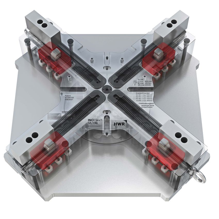
                                                                                                           H W R 04
INOFlex® VL
                                               4-Backen-Handspannfutter gewichtserleichtert
                                               mit Fliehkraftausgleich
                                               4-jaw weight reduced manual chuck with
                                               centrifugal force compensation

ANWENDUNG                                                           APPLICATION
• Spannen von runden, quadratischen/rechteckigen                    • Clamping of round, square/rectangular
  und geometrisch unregelmäßigen Bauteilen                            and irregular parts
• Für den Einsatz auf Fräs-/Drehzentren                             • For milling/turning centers
• Innen- und Außenspannung                                          • Internal and external clamping

TECHNISCHE MERKMALE                                                 TECHNICAL FEATURES
•   Zentrisch ausgleichendes Spannen mit 4 Backen                   •   Centric compensating clamping with 4 jaws
•   Zentrisch spannen mit 2 Backen                                  •   Centric clamping with 2 jaws
•   Spannung mit Festanschlag                                       •   Clamping with ixed stop
•   Gewichtserleichtert                                             •   Weight reduced
•   Mit Fliehkraftausgleich                                         •   with centrifugal force compensation

Technische Daten                                   VL042    VL060              VL070         VL100            VL120
technical information

Ident-Nr. / ident-no.                              846042   846060             846070        846100           846120

Durchmesser / diameter                    mm       420      600                700           990              1150

Hub pro Backe                             mm       5,2      11,1               11,1          11,3             11,3
radial jaw stroke
Ausgleichshub                             mm       3,5      9,1                9,1           9,3              9,3
compensation
max. Anzugsmoment                         Nm       145      185                185           280              280
max. torque
max. Spannkraft bei 4 Backen              kN       110      135                135           200              200
max. gripping force with 4 jaws
max. Spannkraft bei 2 Backen              kN       55       67,5               67,5          100              100
max. gripping force with 2 jaws
max. Drehzahl                             1/min    1800     1300               1200          850              750
max. speed                                r.p.m.
Masse (ohne Backen)                       kg       90       179                215           561              691
weight extension set (without top jaws)
Massenträgheitsmoment                     kg • m2 1,6       6,2                9,9           52,4             86,9
moment of inertia
Nutenstein                                —        GP11     GP11               GP11          GP13             GP13
standard t-nut
Standard weiche Aufsatzbacke              —        VS16     VP16               VP16          VP21             VP21
standard soft jaw
Standard harte Aufsatzbacke               —        VG16     VR16               VR16          VR21             VR21
standard hard jaw

                    H W R 05
[ INOFlex ]

                                                                                                       INOFlex®
  INOFlex® VL
  Spannkraft-/Drehzahl-Diagramm
  Clamping force - speed diagram

                                                                                                       01
                                                                 VL100                 VL120
• Alle Größen jetzt mit Fliehkraftausgleich
  erhältlich                                                     990                   1150

  all sizes now available with                                   50                    50

  centrifugal force compensation                                 M6; 14,3 tief         M6; 14,3 tief

                                                                 410                   410

                                                                 283                   282,5
• Spannung mit Festanschlägen                                    183                   183
  clamping with fixed jaws                                       846                   —

                                                                 886                   988

• höchste Zentrier- und WiederholgenauigkeitM20; 22 tief         M20; 22 tief          M20; 22 tief

  highest centering and repeat accuracy                          176,5                 176,5

                                                                 8,6                   8,6

                                                                 408,7                 490,8
• min. Gewicht durch max. Materialersparnis                      55                    55
  min. weight due to max. material savings                       9,8                   9,8

                                                      Modul 2    Modul 2               Modul 2

• abgedichtet gegen Schmutz                                      2,5                   2,5

  sealed against dirt                                            10                    10

                                                                 495,5                 574,3

                                                                 78                    78
• verwendbar als Zentrierspanner mit 2 Backen
                                                                 21                    21
  use as centering vise with 2 jaws                              30                    30

                                                      41 / 279   43 / 399              43 / 482

• höchste Spannkräfte und Drehzahlen                             21                    21

  highest clampingforces and speed                    M12 x 30   M16 x 35              M16 x 35

                                                                 22                    22

                                                                 37                    37
• minimal Aufbauhöhe in Z
                                                                 38                    38
  minimal height in Z                                            16                    16

                                                                 105                   105

                                                                 57                    57

                                                                 390,75                465,75

                                                                 24                    24

                                                                 142,5                 142,5

                                                                 118,5                 118,5

                                                                 8                     8

                                                                            H W R 06
[ INOFlex ]

                                                              INOFlex® VL

                                                   INOFlex® VLVL 042 – VL 070
                                                              VL 120
                                                                                                             D
                                                                                                             D1
                                                                                                                                 R
                                                   4-Backen-Handspannfutter
                                                                       z1
                                                                            gewichtserleichtert
                                                   4-jaw weight reduced manual chuck
                                                                                   z2

                                                                           z                                                             L
                                                                                           ØC

                                                                                                                                G1        l1
ANWENDUNG                                                                           APPLICATION
• Spannen von runden, quadratischen/rechteckigen                                    • Clamping of round, square/rectangular

                                                                                                                                                   z3
                                                                                                                                                   M
                                                                                                                                                    n
  und geometrisch unregelmäßigen Bauteilen                                            and irregular parts
• Für den Einsatz auf Fräs-/Drehzentren                                             • For milling/turning centers
                                                                                                                                              l2
• Innen- und Außenspannung                                                          • Internal and external clamping                                    P

                                                                                                                                 y1
TECHNISCHE MERKMALE                                                                 TECHNICAL FEATURES

                                                                                           y2
•    Zentrisch ausgleichendes Spannen mit 4 Backen                                  •   Centric compensating clamping with
                                                                                                                       A 4 jaws

                                                                                    E1
•    Zentrisch spannen mit 2 Backen                                                 •   Centric clamping with 2 jaws
•    Spannung mit Festanschlag                                                      •   Clamping with fixed stop            Ansicht A
•    Gewichtserleichtert                                                            •   Weight reduced                     x
•    Mit Fliehkraftausgleich

                                                                                                                                                   x3
                                                                                                                                 x2
    Technische Daten                                   VL042                VL060                VL070                 VL100             VL120
    technical information                                                                                                                 x1

    Ident-Nr. / ident-no.                              846042               846060               846070                846100            846120

    Durchmesser / diameter                    mm       420                  600                  700                   990               1150
                                                                                                                       VL 100
    Hub pro Backe                             mm       5,2                  11,1                 11,1                  11,3          A   11,3
    radial jaw stroke                                                Detail B              s

                                                                                                                                         E1
    Ausgleichshub                             mm       3,5                  9,1                   Q2
                                                                                                 9,1                   9,3               9,3
    compensation
    max. Anzugsmoment                         Nm       160                  200                  200                   320               320
    max. torque                                                                                 Q1                                                 D
                                                                      N            z4
    max. Spannkraft bei 4 Backen              kN       100                  125                  125                   180               180
    max. gripping force with 4 jaws
    max. Spannkraft bei 2 Backen              kN       50                   62,5                 62,5                  90                90
                                                                                                                        E

    max. gripping force with 2 jaws
    max. Drehzahl                             1/min    1200                 900                  800                   700               600
    max. speed                                r.p.m.            B

    Masse (ohne Backen)                       kg       85                   172                  209                   535               666
    weight extension set (without top jaws)                                                              o                                         H
    Massenträgheitsmoment                     kg • m2 1,6                   6,2                  9,9                   52,4              86,9
    moment of inertia
    Nutenstein                                —        GP11                 GP11                 GP11                  GP13              GP13
                                                                                          W
    standard t-nut                                                                                                H1
    Standard weiche Aufsatzbacke              —        VS16                 VP16                 VP16                  VP21              VP21
    standard soft jaw                                                               U            B1
    Standard harte Aufsatzbacke               —        VG16                 VR16                 VR16   ØB             VR21              VR21
    standard hard jaw                                                                                   ØA

                        H W R 05
[ INOFlex ]

                                                                                                                                      INOFlex®
                                                          Anbindung: maschinenspezifisches Befestigungsbohrbild nach Kundenvorgaben
                                                          Connection: machine specific bore pattern as per customer request

                                                                                                                                      01
Abmessungen                                VL042           VL060             VL070              VL100                 VL120
dimensions

                                  A mm     420             600               700                990                   1150

                                B G7 mm    50              50                50                 50                    50

                                  B1 mm    M6; 7,4 tief    M6; 6,2 tief      M6; 6,2 tief       M6; 14,3 tief         M6; 14,3 tief

                                  C mm     250             315               315                410                   410

                                  D mm     149             188               188,6              283                   282,5

                                  D1 mm    116             120               120                183                   183

                                   E mm    —               —                 —                  846                   —

                                  E1 mm    383             535,5             610                886                   988

                                 G1 mm     M12; 20 tief    M20; 22 tief      M20; 22 tief       M20; 22 tief          M20; 22 tief

                                  H mm     121             142               142                176,5                 176,5

                                  H1 mm    8,6             8,6               8,6                8,6                   8,6

                                   L mm    168             233               283,5              408,7                 490,8

                                  M mm     40              40                40                 55                    55

                                  N mm     5               7,8               7,8                9,8                   9,8

                                  P mm     1,5 x 60°       Modul 2           Modul 2            Modul 2               Modul 2

                                 Q1 mm     3               1,2               1,2                2,5                   2,5

                                 Q2 mm     11,4            10                10                 10                    10

Futter geöffnet / chuck open      R mm     208,9           299,4             349,4              495,5                 574,3

                                  U mm     53              62                62                 78                    78

Schlüsselweite / wrench width     W mm     17              17                17                 21                    21

                                  l1 mm    30              30                30                 30                    30

min./max .                        l2 mm    41 / 148        41 / 225          41 / 279           43 / 399              43 / 482

                                n H8 mm    16              16                16                 21                    21

                                   s mm    M12 x 30        M12 x 30          M12 x 30           M16 x 35              M16 x 35

                                x H12 mm   14              14                14                 22                    22

                                  x1 mm    23              23                23                 37                    37

                                  x2 mm    25              25                25                 38                    38

                                  x3 mm    9               9                 9                  16                    16

                                  y1 mm    40              88                88                 105                   105

                                  y2 mm    40              61                61                 57                    57

                                   z mm    170             246               296                390,75                465,75

                                z1 G7 mm   20              22                22                 24                    24

                                  z 2 mm   50              70                70 (2x)            142,5                 142,5

                                  z 3 mm   71,5            60,5              60,5               118,5                 118,5

                                  z4 mm    6               8                 8                  8                     8

                                                                                                           H W R 06
Sie können auch lesen