ProGAV 2.0 IN TOUCH WITH YOU - Christoph Miethke GmbH & Co. KG
←
→
Transkription von Seiteninhalten
Wenn Ihr Browser die Seite nicht korrekt rendert, bitte, lesen Sie den Inhalt der Seite unten

proGAV 2.0                        ®

    IN TOUCH WITH YOU

Patientenhandbuch | Patient Manual | Manuel du patient
Manual para el paciente

CAUTION: US Federal law restricts this device to sale by or on order of a physician!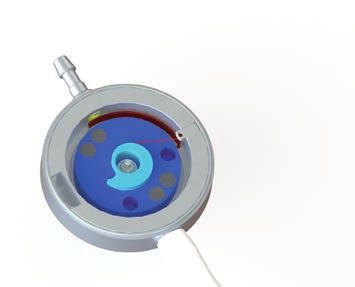
1

                 2

                 3

                 4

                 5

                 6

Abb. 1, Fig. 1

                 1

                 2

                 3

                 6

                 6

                 4

                 5

Abb. 9, Fig. 9

                     3
PATIENTENHANDBUCH | DE
DAS UNTERNEHMEN darin, das Gehirn vor mechanischer Schädigung
zu schützen. Zusätzlich regelt es den Hirninnen-
Die Christoph Miethke GmbH & Co. KG ist ein druck, hält das Hirngewebe feucht und transpor-
Brandenburger Unternehmen, das sich mit der tiert die Stoffwechselprodukte.
Entwicklung, Produktion und dem Vertrieb von
innovativen neurochirurgischen Implantaten zur
Behandlung des Hydrocephalus beschäftigt. Wir KRANKHEITSBILD
arbeiten hierbei erfolgreich mit Kliniken weltweit
zusammen. Beim gesunden Menschen existiert ein Gleichge-
Diese Broschüre soll Ihnen und Ihrer Familie einen wicht zwischen Produktion und Resorption des
Einblick in die Behandlung des Hydrocephalus ge- Hirnwassers. Die täglich produzierte Flüssigkeits-
ben. Erst seit den 50er Jahren ist es möglich, diese menge liegt beim Säugling bei ca. 100 ml, beim
Krankheit erfolgreich zu behandeln. Der Techni- Kleinkind bei ca. 250 ml und beim Erwachsenen
ker John D. Holter hatte in einem dramatischen bei ca. 500 ml. Wird mehr Liquor gebildet als abge-
Wettlauf um das Leben seines an Hydrocephalus baut werden kann, kommt es zur Vergrößerung der
leidenden Sohnes Casey in Philadelphia in weni- Hirnkammern, dem so genannten Hydrocephalus
gen Wochen ein Silikon-Ventil entwickelt. Obwohl (Abb. 2). Der Begriff Hydrocephalus beschreibt ei-
sich dieses Ventil nach seiner Implantation im März nen Zustand, bei dem „Wasser“ (Hydro) im „Kopf“
1956 klinisch bewährt hatte und einen großen (Cephalus) ständig an Volumen zunimmt. Dieser
Schritt in der Behandlung dieser Krankheit dar- Zustand besteht oft schon bei der Geburt (ange-
stellt, gibt es bis heute eine erhebliche Anzahl von borener Hydrocephalus). Er kann sich aber auch
Patienten, die mit Ventilsystemen große Probleme im späteren Leben ausbilden, z.B. durch eine Ent-
haben. zündung oder Blutung, durch eine schwere Verlet-
Die Christoph Miethke GmbH & Co. KG hat die Er- zung am Kopf oder infolge einer Hirnoperation. In
kenntnisse von 50 Jahren Ventilbehandlung aufge- diesen Fällen spricht man von einem erworbenen
griffen und durch die Verwendung des Werkstoffs Hydrocephalus.
Titan eine neue Generation von hochpräzisen
Ventilen entwickelt. Erstmals stehen Ventilsysteme Man unterscheidet außerdem zwischen dem Hy-
zur Verfügung, die konsequent die physikalischen drocephalus occlusus (nicht kommunizierender
Randbedingungen der Hirnwasserableitung be- Hydrocephalus) und dem Hydrocephalus commu-
rücksichtigen und so einen physiologischen Hirn- nicans (kommunizierender Hydrocephalus). Beim
druck unabhängig von der Körperlage einstellen. Hydrocephalus occlusus ist die Verbindung zwi-
schen den Hirnkammern unterbrochen, so dass
Abb. 1: Anatomische Darstellung des Schädels sie nicht miteinander „kommunizieren“ können.
(siehe Umschlaginnenseite)
Wenn die Ventrikel miteinander frei verbunden sind,
1 Schädeldecke
2 Gehirn aber eine Störung der Hirnwasserresorption be-
3 Hirnwasser (Liquor) steht, liegt ein Hydrocephalus communicans vor.
4 Seitlicher Ventrikel
5 Dritter Ventrikel
6 Vierter Ventrikel
ANATOMISCHE GRUNDLAGEN
Das menschliche Gehirn (Abb. 1) ist von einer
speziellen Flüssigkeit, dem Hirnwasser (Liquor),
umgeben. Im Inneren des Kopfes befinden sich
mehrere Hirnkammern, so genannte Ventrikel,
in denen das Hirnwasser produziert wird. Die
Ventrikel sind durch Kanäle untereinander ver-
bunden und stellen ein komplexes Ableitungs-
system dar. Das Wasser zirkuliert durch diese Hirn- a) b)
kammern und wird schließlich in das venöse Blut Abb. 2: Ventrikelgröße
abgegeben. Die Aufgabe des Hirnwassers besteht a) normal b) Hydrocephalus
5DE | PATIENTENHANDBUCH
KRANKHEITSSYMPTOME BEHANDLUNGSMETHODEN
Im Säuglingsalter sind die Schädelknochen noch Obwohl es immer Bemühungen gab, alternative
nicht fest verwachsen. Das zunehmende Hirnwas- Therapiemöglichkeiten zur Ventilimplantation zu
ser führt hier zu einer Zunahme des Kopfumfangs finden, beispielsweise durch die Behandlung mit
unter gleichzeitigem Abbau von Hirngewebe. Ab Medikamenten oder in jüngster Zeit auch durch
einem Alter von ca. 2 Jahren wird durch den har- minimalinvasive chirurgische Eingriffe, gibt es bis
ten Schädel eine Vergrößerung des Kopfumfangs heute in den meisten Fällen keine Alternative zur
verhindert. Hier führt die Flüssigkeitszunahme zu Implantation eines Ableitungssystems, des so
einem enormen Druckanstieg, wodurch sich die genannten „Shunts“. Die Operation ist im Allge-
Hirnkammern erweitern und das Gehirn kompri- meinen weder gefährlich noch schwierig. Die Ab-
miert wird. Sowohl beim Säugling als auch beim leitungssyteme (siehe Abb. 3) bestehen aus Kathe-
Erwachsenen können irreversible Gehirnschäden tern, durch die das Hirnwasser abgeführt wird, und
auftreten. Je nach Grad der Störung kommt es zu einem Ventil zur Regulierung des Hirninnendrucks.
Übelkeit, Kopfschmerzen, Erbrechen, Koordinati- Es wird zwischen ventrikulo-peritonealer (vom Kopf
onsstörung, Schläfrigkeit und schließlich Bewusst- in die Bauchhöhle) und ventrikulo-atrialer (vom
losigkeit. Kopf in den rechten Vorhof des Herzens) Ableitung
unterschieden.
DIAGNOSE DER ERKRANKUNG 1 Rechter Herzvorhof
2 Herzkatheter (atrialer Katheter)
3 Ventil
Dem Arzt stehen heute verschiedene Möglich- 4 Reservoir
keiten zur Diagnose eines Hydrocephalus zur 5 Hirnkammerkatheter (Ventrikelkatheter)
6 Hirnkammern
Verfügung. Mittels bildgebender Verfahren (z.B. 7 Bauchhöhlenkatheter (Peritonealkatheter)
Computertomographie, Ultraschall oder Magnetre- 8 Bauchhöhle
sonanztomographie) wird die Größe der Ventrikel
bestimmt. 4 4
5
6
Computertomographie (CT) 3 3
Bei dieser schnellen und schmerzlosen Unter-
suchung werden durch Röntgenstrahlung Abbil- 2 7
dungen der verschiedenen Schichten des Kopfes 1
erzeugt.
8
Magnetresonanztomographie (MRT)
Dieses schmerzlose bildgebende Verfahren lie-
fert durch elektromagnetische Wellen sehr feine
Schichtbilder des Kopfes. Es wird auch als Kern-
spinresonanztomographie bezeichnet. Abb. 3: Ableitungssysteme
a) ventrikulo-atrial b) ventrikulo-peritoneal
Ultraschall
Nur bei kleinen Kindern kann bei diesem Verfahren
durch die offene Fontanelle das Kopfinnere unter- THERAPIE-KOMPLIKATIONEN
sucht werden.
Die Behandlung des Hydrocephalus mit einem
Durch Druckmessungen kann eine Erhöhung des Shuntsystem ist nicht immer komplikationslos. Es
Hirndrucks festgestellt werden. Kontrastmittelun- kann wie bei jedem chirurgischen Eingriff zu einer
tersuchungen dienen der Untersuchung der Hirn- Infektion kommen. Leider treten auch teilweise
wasserzirkulation. Probleme auf, die direkt oder indirekt mit dem im-
plantierten Ventilsystem in Verbindung stehen kön-
nen. Solche Komplikationen sind Verstopfungen
des Ableitungssystems oder die ungewollt erhöhte
Ableitung des Hirnwassers. Um den physikalischen
6PATIENTENHANDBUCH | DE
Hintergrund zu verstehen, warum sich Ihr Arzt in Ih-
rem Fall für das proGAV 2.0 entschieden hat, lesen
Sie bitte im Kapitel “physikalische Grundlagen”.
0
VERHALTEN NACH DER OPERATION
1
Die Patienten, die mit Ventilsystemen versorgt wer-
den, sind im Normalfall in ihrem täglichen Leben
nicht eingeschränkt. Vor erhöhten Anstrengungen
(körperlich schwere Arbeit, Sport) sollte der behan-
delnde Arzt befragt werden. Treten beim Patienten Abb. 4b: Hirnkammerdruck beim gesunden Menschen in
starke Kopfschmerzen, Schwindelanfälle, unnatür- stehender Position
licher Gang oder Ähnliches auf, sollte unverzüglich
ein Arzt aufgesucht werden.
1 Hirnkammerbehälter
2 Erweiterte Hirnkammer
PHYSIKALISCHE GRUNDLAGEN
Beim gesunden Menschen ist der Hirninnendruck
(hier dargestellt durch Wasserspiegel im Hirnkam-
merbehälter) in der liegenden Körperposition leicht
positiv und in der stehenden 0 oder sogar leicht 0
negativ, siehe Abb. 4.
Besteht ein Hydrocephalus, ist der Hirn-
innendruck unabhängig von der Körperlage erhöht,
die Hirnkammern sind erweitert, siehe Abb. 5. 1 2
Abb. 5a: Hirnkammerdruck beim kranken
Es ist jetzt dringend erforderlich, den Hirninnen- Menschen in liegender Position
druck unabhängig von der Körperhaltung zu sen-
ken und ihn in normalen Grenzen zu halten. Hierzu
wird ein „Shunt“ implantiert, der eine Verbindung
zwischen dem Kopf und der Bauchhöhle herstellt,
um das überschüssige Hirnwasser abzuleiten. Auf-
0
grund von Änderungen der Körperposition kommt
es ständig zu erheblichen physikalischen Verände- 1
rungen im Ableitungssystem.
1 Hirnkammerbehälter
2 Hirnkammer
Abb. 5b: Hirnkammerdruck beim kranken
Menschen in stehender Position
0
Sowohl die Bauchhöhle als auch die Hirnkammern
können vereinfacht als offene Gefäße angesehen
werden, die durch einen Schlauch verbunden sind.
Solange der Patient liegt (Kopf und Bauch befinden
1 2 sich in der gleichen Höhe) und kein Ventil in das
Ableitungssystem integriert ist, haben beide Was-
Abb. 4a: Hirnkammerdruck beim gesunden Menschen in seroberflächen die gleiche Höhe, es handelt sich
liegender Position
um kommunizierende Gefäße (Abb. 6).
7DE | PATIENTENHANDBUCH
1 Hirnkammerbehälter um den Öffnungsdruck des Ventils (Abb. 7a).
2 Hirnkammer Steht der Patient auf, wird so lange Hirnwas-
3 Ableitungsschlauch
ser abgeleitet, bis die Höhendifferenz gemäß
4 Bauchhöhle
5 Bauchhöhlenbehälter dem Öffnungsdruck des Ventils zwischen den
6 Bluterguss beiden Behältern erreicht ist. Der Öffnungs-
7 verkleinerte Hirnkammern
druck des Ventils, der für die liegende Position
ausgelegt ist, liegt aber wesentlich unter der
schon beschriebenen Höhendifferenz zwischen
0
den Hirnkammern und der Bauchhöhle. Auch in
diesem Fall werden die Hirnkammern leergesaugt
und es kommt zu den angesprochenen Proble-
men (Abb. 7b).
a) 1 2 3 4 5 x Ventilöffnungsdruck in der liegenden Position
1 Hirnkammerbehälter
2 Hirnkammer
6 3 Ableitungsschlauch
0 7 4 Bauchhöhle
1 5 Bauchhöhlenbehälter
6 Bluterguss
7 verkleinerte Hirnkammern
3 8 Differenzdruckventil
0 x
5 4
b)
Abb. 6: Hirnwasserableitung nur mit Schlauch, ohne Ventil a) 1 2 3 4 5
a) liegend b) stehend
6
0 7
Die Bauchhöhle kann vereinfacht als Überlaufgefäß 1
aufgefasst werden. Wenn in den Behälter, der die
Hirnkammern darstellt, zusätzlich Flüssigkeit gefüllt 3
wird, bleibt der Wasserspiegel im Hirnkammerbe-
hälter gleich, denn die Flüssigkeit wird schnell in
die Bauchhöhle abgeleitet. Steht der Patient auf, x
befinden sich die Hirnkammern wesentlich hö- 5 4
her als die Bauchhöhle. Es kommt jetzt so lange 8
zu einer Ableitung des Hirnwassers durch den b)
Schlauch, bis beide Wasseroberflächen wieder
Abb. 7: Hirnwasserableitung mit konventionellem Ventil
die gleiche Höhe haben. In diesem Fall ist aber der a) liegend b) stehend
Hirnkammerbehälter völlig leer gelaufen. Da die
Hirnkammern keine starren Behälter sind, führt das Das einfache Schema macht deutlich, wie wichtig
Leerlaufen und der damit einhergehende Sogeffekt es ist, ein Ventil zu implantieren, das für die stehen-
zum Zusammenziehen der Hirnkammern. Eine de Position einen wesentlich höheren Öffnungs-
Folge hiervon kann der angesprochene Verschluss druck hat (entsprechend dem Abstand zwischen
des Ableitungssystems sein. Das Hirnwasser Gehirn und Bauch) als für die liegende Position.
wird übermäßig herausgesaugt, das Gehirn wird Das proGAV 2.0 ist ein solches Ventil. In jeder Kör-
deformiert. Durch diese Überdrainage kann es im perposition stellt es den für den Patienten erfor-
Gehirn zu Wasser- oder Blutansammlungen zwi- derlichen Hirninnendruck ein. Die beschriebenen
schen Gehirn und Schädelknochen kommen. Probleme und Komplikationen werden vermieden,
Wird ein konventionelles Ventil in das Ableitungs- indem die ungewollte Ableitung einer erhöhten
system eingesetzt, bewirkt dies eine Erhöhung Menge von Hirnwasser verhindert wird (Abb. 8).
des Wasserspiegels im Hirnkammerbehälter
8PATIENTENHANDBUCH | DE
x Ventilöffnungsdruck in der liegenden Position kraft eine Erhöhung des Ventilöffnungsdrucks rea-
1 Hirnkammerbehälter lisiert. Je aufrechter der Oberkörper des Patienten
2 Hirnkammer ist, desto größer ist der Öffnungsdruck des gesam-
3 Ableitungsschlauch
ten proGAV 2.0.
4 Bauchhöhle
5 Bauchhöhlenbehälter Das proGAV 2.0 besteht aus ausschließlich hoch-
6 proGAV 2.0 wertigen Materialien, die für die Anwendung als
Implantatwerkstoffe erprobt und normiert sind,
Hauptbestandteil ist Titan. Durch das stabile Ge-
häuse werden Einflüsse (z.B. Druck von außen)
x
auf die Ventilfunktion auf ein vernachlässigbares
CHRISTOPH MIETHKE
proGAV
0...20
Minimum reduziert. Somit sind eine hohe Funkti-
onssicherheit und damit eine lange Lebensdauer
garantiert.
a) 1 2 3 4 5 Das proGAV 2.0 ist ein verstellbares Ventil. Durch
die Rotorbremse ist ein ungewolltes Verstellen
durch äußere einwirkende Magnetfelder ausge-
0 2
proGAV
0...20
CHRISTOPH MIETHKE
schlossen.
1
Die Verstelleinheit des proGAV 2.0 ist mit einem
3 Feedbackmechanismus ausgestattet. Wird Druck
6 auf das Ventil ausgeübt, ist aufgrund der Beschaf-
fenheit des Ventilgehäuses ein akustisches Signal
- ein Klickton - hörbar bzw. ein Widerstand fühlbar
0
sobald die Rotorbremse gelöst ist. Das Ventil zeigt
5 4
also akustisch bzw. haptisch an, wann der Druck
b) für eine Entkopplung ausreicht.
Wird dieser Druck anschließend wieder gelöst,
Abb. 8: Hirnwasserableitung mit dem proGAV 2.0 ist der Rotor wieder verstellsicher. Während das
a) liegend b) stehend
Klicken beim Lösen der Rotorbremse vor der Im-
plantation immer gut zu hören ist, kann es nach
VENTILMECHANISMUS der Implantation und Befüllung des Ventils je nach
Lage und Beschaffenheit der Implantatumgebung
Das proGAV 2.0 ist ein lageabhängig arbeiten- deutlich gedämpft sein. In der Regel sollte es aber
des Hydrocephalusventil. Es besteht aus einem durch den Patienten selbst oder aber mittels eines
Federventil mit verstellbarem Ventilöffnungsdruck Stethoskops hörbar sein.
(Verstelleinheit) und einem Gravitationsventil (Gra-
vitationseinheit). Auf diese Weise kann in jeder Warnhinweis: Ein Drücken auf das Ventil sollte
Körperposition eine für den individuellen Patienten dem behandelnden Arzt vorbehalten sein.
optimale Liquor-Ableitung sichergestellt werden.
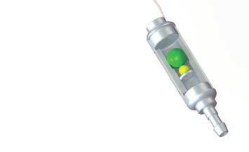
Abb. 9: Funktionszeichnung des proGAV 2.0
(siehe Umschlaginnenseite)
1 Saphirkugel
2 Stabfeder 15 mm
17 mm
3 Rotor
4 Tantalkugel Abb. 10: proGAV 2.0 im Maßstab 1:1
5 Saphirkugel
6 Konnektor unter dem Katheter
Warnhinweis: Das Ventilsystem kann ein pump-
Die Verstelleinheit reguliert den Hirndruck, wenn bares Reservoir enthalten. Da häufiges Pum-
der Patient liegt. Dieser Öffnungsdruck kann auch pen zu einer übermäßigen Wasserableitung
nach der Implantation durch die Haut verändert und damit zu sehr ungünstigen Druckverhält-
werden, ohne dass eine erneute Operation not- nissen führen kann, sollte dieser Vorgang dem
wendig ist. Arzt vorbehalten bleiben.
Sobald sich der Patient aufrichtet, wird eine Tan-
talkugel aktiviert, die zusätzlich durch ihre Schwer-
9DE | PATIENTENHANDBUCH
PATIENTENPASS Lumbalpunktion
Punktion des Rückenmarkskanals am unteren Teil
Jedem proGAV 2.0 liegt ein Patientenpass bei. der Wirbelsäule
Dieser wird vom behandelnden Arzt ausgefüllt und
enthält so wichtige Informationen für die Nachun- Lumbo-peritoneale Ableitung
tersuchungen. Ableitung des Hirnwassers aus der Hirnkammer
über den Lendenwirbelbereich in die Bauchhöhle
KLEINES PATIENTENLEXIKON
Meningen
Anatomie Hirn- bzw. Rückenmarkshäute
Lehre vom Bau der Körperteile
Meningitis
Arachnoidea Spinnwebenhaut; Entzündung der Hirnhaut
Bindegewebige Membran, die sich über Furchen
und Windungen des Gehirns und das Rückenmark Minimalinvasiv
zieht Minimal eindringend
Computer-Tomographie (CT) Peritoneum
Bildgebendes Verfahren, bei dem durch Röntgen- Haut, die die Bauch- und Beckenhöhle auskleidet
strahlung Schichtbilder erzeugt werden
Pia mater
Drainage Gefäßführender Teil der weichen Hirnhaut
Ableitung einer Flüssigkeitsansammlung
Punktion
Dura mater Einstich einer Hohlnadel oder eines Trokars in Ge-
Harte Hirnhaut fäße zur Entnahme von Flüssigkeiten
Fontanelle Resorption
Bindegewebige Knochenlücke am kindlichen Aufsaugung bzw. Aufnahme von Stoffen über
Schädel, die später verknöchert Haut, Schleimhaut oder Gewebe
Hirnventrikel Rückenmark
Mit Hirnwasser gefüllte Gehirnkammer Im Wirbelkanal eingeschlossener Teil des Zentra-
len Nervensystems
Implantat
Produkt, das zur Erfüllung bestimmter Ersatzfunk- Shunt
tionen für einen begrenzten Zeitraum oder auf Le- Kurzschlussverbindung, hier Katheterableitungs-
benszeit in den menschlichen Körper eingebracht system mit integriertem Ventil
wird
Subdurales Hämatom
Katheter Blutgerinnsel zwischen Gehirn und Schädeldecke
Schlauch
Subkutandruck
Kommunizierende Gefäße Druck unter der Haut
Gefäße, die über einen Kanal miteinander verbun-
den sind Überdrainage
Ungewollter, erhöhter Abfluss von Hirnwasser
Leptomeninx
Weiche Hirnhaut, die sich unterteilt in Arachnoidea Ventrikulo-peritoneale Ableitung
und Pia mater Ableitung des Hirnwassers aus der Hirnkammer
direkt in die Bauchhöhle (Bauchhöhlenkatheter)
Liquor (liquor cerebrospinalis)
Gehirn-Rückenmark-Flüssigkeit oder Hirnwasser
Liquorbestandteile Hirnwasserbestandteile
10PATIENTENHANDBUCH | DE
NACHUNTERSUCHUNGEN
Eine Nachuntersuchung ist in jedem Fall erforderlich.
Datum Behandlung
Notizen und Anmerkungen
11GB | PATIENT MANUAL
THE COMPANY CLINICAL PICTURE OF THE CONDITION
Christoph Miethke GmbH & Co. KG is a Branden- In healthy humans, a balance exists between the
burg-based company that develops, manufactures production and resorption of cerebrospinal fluid.
and markets innovative neurosurgical implants for In infants, approx. 100 ml of this fluid is produced
the treatment of hydrocephalus. In this, we work every day; in small children, the daily production
in successful partnerships with numerous hospitals is approx. 250 ml, in adults approx. 500 ml. If the
worldwide. amount of fluid produced exceeds the amount re-
The purpose of this booklet is to provide you and sorbed, the ventricles expand, leading to the con-
your family with some understanding of the treat- dition known as hydrocephalus (fig. 2). The term
ment of hydrocephalus. The successful treatment hydrocephalus refers to the continuous increase
of this condition has only been possible since the of the volume of “water” (hydro) in the “head” (ce-
1950s. In a dramatic race against time to save the phalus). This condition is often observed at birth
life of his son, Casey, who suffered from hydroce- (congenital hydrocephalus), but it can also deve-
phalus, a technician named John D. Holter deve- lop later in life, e.g., as the result of inflammation,
loped, in only a few weeks, a novel silicone valve. hemorrhage or severe head injury, or after brain
Despite the fact that, since its first implantation in surgery. Such cases are referred to as acquired
March 1956, this valve has proven to be clinically hydrocephalus.
effective and a giant step in the treatment of this A further distinction is made between obstructive
condition, there are many patients today who ex- hydrocephalus and communicating hydrocepha-
perience considerable problems with hydrocepha- lus. In obstructive hydrocephalus, the links bet-
lus valve systems. ween the ventricles of the brain are interrupted
Christoph Miethke picked up the knowledge gained so that the ventricles cannot “communicate” with
in 50 years of valve treatment and developed a each other. Cases in which the ventricles are in-
new generation of highprecision valves made of terlinked through open channels, but resorption of
the metal titanium. For the first time, there are valve cerebrospinal fluid is impaired, are diagnosed as
systems available that consistently take into ac- communicating hydrocephalus.
count the physical conditions of brain fluid drai-
nage and can thus maintain a physiological brain
pressure, independent of the body position of the
patient.
Fig. 1: Anatomic sketch of the cranium (inner cover page)
1 skull pan
2 brain
3 cerebrospinal fluid
4 lateral ventricle
5 third ventricle a) b)
6 fourth ventricle
Fig. 2: Ventricle size
BASIC ANATOMY a) normal, b) hydrocephalus
The human brain (fig. 1) is surrounded by a spe-
cial fluid known as cerebrospinal fluid (CSF). Ce- CLINICAL SYMPTOMS OF THE CONDITION
rebrospinal fluid is produced in several chambers,
so-called ventricles, that are found within the brain. In infants, the cranial bones have not adhered so-
The channels, by which the ventricles are intercon- lidly yet. The increasing volume of cerebrospinal
nected, constitute a complex drainage system. fluid causes the head to increase in circumference
The fluid in the brain circulates through these while, at the same time, brain tissue disintegrates.
ventricles and eventually flows into the venous From the age of about 2, the hardened skull pre-
blood. The function of this fluid is to protect the vents any growth of the head's circumference. In
brain from mechanical damage. The CSF also that situation, the increase in fluid volume leads to
regulates the internal brain pressure (intracranial a massive pressure rise, resulting in the expansion
pressure, ICP), keeps the brain tissue moist and of the brain ventricles and the compression of the
transports the products of metabolism. brain itself. The consequence for infants and adults
12PATIENT MANUAL | GB
can be irreversible brain damage. Symptoms (de- head to the right atrium of the heart). In special
pending on the severity of the disorder) include cases, there is also the option of implanting a lum-
nausea, headache, vomiting, impaired coordinati- bo-peritoneal shunt (from the spine canal into the
on, drowsiness and, in the end, unconsciousness. abdominal cavity).
1 right atrium
2 heart catheter (atrial catheter)
DIAGNOSIS OF THE CONDITION 3 valve
4 reservoir
Doctors have a variety of ways at their disposal 5 ventricular catheter
6 ventricles
to diagnose hydrocephalus. The ventricle size 7 abdominal catheter (peritoneal catheter)
is measured through imaging procedures (e.g. 8 abdominal cavity
computerized tomography, ultrasound or NMR-
tomography).
4 4
5
Computerized tomography (CT) 6
This quick and painless diagnostic procedure pro- 3 3
duces X-ray images of different layers of the head.
2
Nuclear Magnetic Resonance (NMR) tomography 1 7
This painless electromagnetic imaging process
produces images of very fine layers of the head.
It is also known as NMR, MRT, or MRI scanning. 8
Ultrasound
This procedure, in which the interior of the head is
examines through the open fontanel, can only be a) b)
applied to small children.
Fig. 3: Drainage systems for hydrocephalus patients
a) ventriculo-atrial, b) ventriculo-peritoneal
Another way of diagnosing hydrocephalusis
through pressure measurements showing an incre-
ased brain pressure. The circulation of cerebrospi- THERAPY COMPLICATIONS
nal fluid is investigated through examinations with
contrast agents. The treatment of hydrocephalus with a shunt sys-
tem can sometimes arise complications. As is the
case for any surgical intervention, there is a risk of
METHODS OF TREATMENT infection. There can also be complications that are
directly or indirectly related to the implanted val-
For all the efforts to find therapeutic alternatives to ve system. Such complications include blockages
valve implantation (e. g. through pharmaceutical of the drainage system or inadvertently increased
treatment or, most recently, by minimally invasive fluid drainage. To give you an understanding why
surgery), there is currently no alternative, in most your physician decided for the proGAV 2.0, the
cases, to the implantation of a drainage system, physics of drainage is explained in the chapter
referred to as a shunt. The operation is usually neit- “Physics background“.
her risky nor difficult. The drainage system (fig. 3) is
comprised of catheters that drain off the cerebro-
spinal fluid and a valve that regulates intracranial AFTER THE OPERATION
pressure. In many cases, a reservoir is implanted
between the ventricle catheter and the valve. The As a rule, the everyday activities of patients with
doctor uses this reservoir for checking the patency shunt implants are not restricted. However, pati-
of the valve, to siphon off CSF-samples or to inject ents should consult their attending physician be-
medicines. fore major physical exertion (e. g. hard physical
A distinction is made between two types of drai- work, strenuous sports). Hydrocephalus patients
nage: ventriculo-peritoneal (from the head to the who experience headache, dizziness, unnatural
abdominal cavity) and ventriculo-atrial (from the gait or similar symptoms should consult a physi-
13GB | PATIENT MANUAL
cian without delay. Apart from that, we recommend 1 ventricle container
medical check-ups at regular intervals. The patient 2 expanded ventricles
should avoid knocks or pressure on the valve and
catheters. The valve has been designed to be resi-
stant against magnetic fields.
PHYSICS BACKGROUND
0
In the following chapter we describe the pressure
conditions relevant for hydrocephalus drainage.
The ventricle pressure and the pressure in the ab-
dominal cavity are represented by water levels.
In a healthy human, the ventricular pressure (water 1 2
Fig. 5a: Ventricle pressure in a hydrocephalus patient in
level in the ventricle container) is positive (slightly horizontal position
above 0) in the horizontal position and negative
(slightly below 0) in the upright (vertical) position
(fig. 4).
1 ventricle container
2 ventricles
0
1
0
Fig. 5b: Ventricle pressure in a hydrocephalus patient in
vertical position
1 2
Now there is an urgent need to lower the intracra-
Fig. 4a: Ventricle pressure in a healthy nial pressure and keep it within normal limits, in-
human in horizontal position
dependent of the body position. Finally, excessive
cerebrospinal fluid is drained into the abdominal
cavity. Due to changes in the patient’s body posi-
tion, the drainage system is subject to incessant,
considerable physical changes. Fig. 6 shows the
0
effects on the intracranial pressure when a tube is
1 implanted, although there has been no valve inte-
grated in the drainage system yet.
For simplicity, the abdominal pressure as well as
the ventricles can be regarded as open vessels,
which are now connected by a tube. As long as
the patient is lying down (head and abdomen at
the same height) and no valve is integrated in the
Fig. 4b: Ventricle pressure in a healthy
drainage system, both water levels are at the same
human in vertical position
height, too: It is a system of communicating ves-
sels. In a simplified picture, the abdomen can be
In hydrocephalus patients the ventricular pressure regarded as an overflow vessel. Even if more fluid is
is always increased (water level in the ventricle con- filled into the ventricle container, the water level in it
tainer far above 0) irrespective of the body position. will remain at the same height, because the fluid is
The ventricles are expanded (see fig. 5). instantly drained into the abdomen. When the pa-
14PATIENT MANUAL | GB
tient stands up, the ventricles are at a significantly pressure corresponding to the height difference
higher level than the abdomen. In this case, the between the ventricles and the abdomen. Hence,
fluid is drained through the tube until both water le- the ventricles will still drained empty, resulting in
vels are at the same height. This means, however, the above mentioned problems (fig. 7).
that the ventricle container is emptied completely.
x opening pressure in horizontal position
Since the ventricles do not have rigid walls, this
1 ventricle container
emptying, in accordance to the siphon effect, 2 ventricle
leads to a contraction of the ventricles. This, in 3 drainage tube
turn, can result in the above mentioned blockage 4 abdominal cavity
5 abdominal container
of the drainage system. The cerebrospinal fluid is 6 accumulated water or blood
sucked out of the ventricles and the brain suffers 7 contracted ventricles
deformation. And when the brain contracts, the re- 8 valve
sulting open space between brain and skull bone
can fill up with water or blood (fig. 6). x
1 ventricle container
2 ventricle
3 drainage tube
4 abdominal cavity
a) 1 2 3 4 5
5 abdominal container
6 accumulated water or blood
7 contracted ventricles
6
0 7
0 1
3
a) 1 2 3 4 5 x
5
8 4
6 b)
0 7
1 Fig. 7: Ventricle drainage with conventional valve
a) horizontal, b) vertical
3
The following sketch demonstrates the importance
of implanting a valve that offers a significantly high-
er opening pressure for the vertical position (cor-
0
5
responding to the distance between the brain and
4 the abdomen) than for the horizontal position.
b)
The proGAV 2.0 is such a valve. It sets the required
intracranial pressure for the patient in every body
Fig. 6: Ventricle drainage without a valve position. The problems and complications descri-
a) horizontal, b) vertical
bed above are avoided by preventing any uninten-
tional overdrainage of cerebrospinal fluid (fig. 8).
A conventional valve integrated into the draina-
ge system causes a rise of the water level in the
ventricle container, by exactly the opening pres-
sure of the valve (fig.7a). When the patient stands
up, cerebrospinal fluid is drained off until the height
difference between the two containers for the ho-
rizontal position is reached. However, the opening
pressure of the valve, which was adjusted for the
horizontal position, is considerably lower than the
15GB | PATIENT MANUAL
x opening pressure in horizontal position
1 ventricle container
2 ventricles
3 drainage tube
4 abdominal cavity
5 abdominal container 17 mm 15 mm
6 proGAV 2.0
Fig. 10: proGAV 2.0, Scale 1:1
The proGAV 2.0 is a hydrocephalus valve who-
x
se mode of operation depends on its position. It
CHRISTOPH MIETHKE
proGAV
0...20
consists of a spring valve with adjustable opening
pressure, and a gravitational valve. In this way it
can be ensured that optimal CSF drainage is
a) 1 2 3 4 5
maintained for every individual patient, indepen-
dent of the body position of the patient.
The adjustable valve controls the intracranial pres-
sure if the patient is in a horizontal position. This
opening pressure can be changed post-operative
0 2
through the skin, without necessitating any further
proGAV
0...20
CHRISTOPH MIETHKE
1
surgical intervention. As soon as the patient moves
3 to an upright position, a tantalum ball is activated,
6 which, by its weight, sets the opening pressure of
the valve to a higher value. The closer the upper
body of the patient is to the vertical position, the
0
higher the total opening pressure of the proGAV
5 4
2.0.
b)
The proGAV 2.0 is made only of high-grade ma-
Fig. 8: Ventricle drainage with proGAV 2.0 valve terials that have been tested and standardized for
a) horizontal, b) vertical
use in implants. The main material is titanium. The
robust housing of the valve ensures that any influ-
ences (e. g. external pressure) on the functioning of
the valve are reduced to an insignificant minimum.
TECHNICAL SPECIFICATIONS OF THE VALVE This guarantees a high level of functional safety
and a long service life.
The proGAV 2.0 is a combination of an adjustable
valve and a gravitational valve.
The proGAV 2.0 is equipped with a feedback-
Fig. 9: Schematic cross section of the proGAV 2.0 (see mechanism. When using the proGAV 2.0 Adjust-
inner cover page)
ment Tool, pressure on the housing of the valve is
1 sapphire ball
2 torsion bar created and a resulting acoustic signal (a clicking
3 rotor sound) is produced due to the unique construction
4 tantalum ball of the valve housing. This clicking sound indicates
5 sapphire ball
6 connector underneath the silicone catheter that the brake of the rotor is released. Now the
rotor can rotate freely. Once the pressure on the
valve is released, a clicking sound is heard and the
rotorbrake is again locked safely so that the valve is
In particular cases, the adjustable valve can be im- safe against spontaneous readjustments.
planted on its own. The dimensions are shown in
fig. 10. The clicking sound is well recognizable before im-
plantation. However after implantation, once the
valve is filled up, depending on place and texture
16PATIENT MANUAL | GB
of the surrounding area of the implant, the acoustic
signal could be considerably muted. The clicking
sound should generally be audible by the patient
itself or via a stethoscope.
Warning note: Applying pressure on the feed-
back-mechanism is restricted to the physician.
Warning note: The shuntsystem may comprise
a reservoir that can be pumped. Since frequent
pumping may lead to overdrainage and thus to
very unfavourable pressure conditions, such
pumping should only be carried out by the phy-
sician.
PATIENT ID
Each proGAV 2.0 is supplied with an individual pa-
tient ID. The ID is filled out by the attending phy-
sician and contains important information for the
follow-up examinations.
17GB | PATIENT MANUAL
A BRIEF PATIENT GLOSSARY Meningitis
Inflammation of the meninx
Anatomy
A guide to the structure of body components Minimally invasive
Minimally infiltrating
Arachnoid
Connective tissue in the brain that lies between the Overdrainage
dura mater and the pia mater Undesirable outward flow of cerebrospinal fluid
Catheter Peritoneum
Tube Membrane that covers the pelvic and abdominal
cavities
Cerebrospinal fluid
Watery spinal fluid in the brain Pia mater
Component of the soft meninx containing blood
Communicating vessels vessels
Vessels that are connected by a channel
Piaarachnoid
Computed tomography (CT) Soft component of the meninx that is divided into
Imaging technique whereby „slices“ of the body are the arachnoidea and pia mater
recorded with an X-ray scanner
Puncture
Drainage Insertion of a hollow needle or a trocar into a vessel
Drainage of accumulated fluid for the purpose of removing fluid
Dura mater Resorption
The hardest component of the meninx Suctioning or removal of material through skin,
mucosa or tissue
Fluid component
Cerebrospinal fluid component Shunt
A passage between two channels – here a catheter
Fontanel drainage system with an integrated valve
Connective tissue opening in a young infant’s skull
that later ossifies Spinal column
Element of the central nerous system located
Implant within the vertebral channel
Substance that is placed in the human body to re-
place a particular function for a limited period of Subcutaneous pressure
time or for the rest of the patient’s life Pressure beneath the skin
Lumbar puncture Subdural hematoma
Puncture of the spinal channel at the lower spine An accumulation of blood between the brain and
cranium
Lumboperitoneal drainage
Drainage of cerebrospinal fluid from the ventricle Ventricle of the brain
of the brain, by way of the region of the lumbar Intracranial space containing cerebrospinal fluid
vertebrae in the abdominal cavity
Ventricular peritoneal drainage
Meninges Drainage of cerebrospinal fluid from the ventri-
Membrane found in the brain and spine cle of the brain directly into the abdominal
cavity (abdominal catheter)
18PATIENT MANUAL | GB
FOLLOW-UP EXAMINATIONS
A follow-up examination must be carried out in all cases.
Date Treatment
Notes and comments
19ES | MANUAL PARA EL PACIENTE
UNA EMPRESA CUADRO CLÍNICO
Christoph Miethke GmbH & Co. KG es una empre- En las personas sanas existe un equilibrio entre
sa de Berlín dedicada al diseño, fabricación y dis- la producción y la resorción de líquido cefalor-
tribución de innovadores implantes neuroquirúrgi- raquídeo. La cantidad de líquido producida di-
cos para el tratamiento de la hidrocefalia. Para ello ariamente en un recién nacido es de aproxima-
contamos con la colaboración de distintas clínicas damente 100 ml, en un niño pequeño de 250 ml y
en el mundo entero. en un adulto de 500 ml. Si se produce más líquido
Con este prospecto, usted y su familia podrán for- del que se puede eliminar, se produce un aumento
marse una idea general acerca del tratamiento de del tamaño de las cavidades cerebrales, la deno-
la hidrocefalia. Hasta los años 50 no empezaron a minada hidrocefalia (fig. 2). El término hidrocefa-
verse los primeros resultados del tratamiento de lia describe un estado, en el cual el volumen de
esta enfermedad. „agua“ (hidro) en la „cabeza“ (cefalia) incrementa
En Filadelfia el científico John D. Holter fabricó constantemente. A menudo este estado ya se
en pocas semanas una válvula de silicona, en un presenta al nacer (hidrocefalia congénita). Pero
intento desesperado de salvar la vida de su hijo también puede desarrollarse posteriormente, p. ej.
Casey que padecía de hidrocefalia. La eficacia de debido a una inflamación, una herida grave en la
esta válvula fue probada clínicamente tras su im- cabeza, un tumor canceroso o como secuela de
plantación en marzo de 1956 y, aunque supuso un una meningitis. En estos casos se suele hablar de
gran avance en el tratamiento de la enfermedad, una hidrocefalia adquirida.
hoy en día sigue habiendo una gran cantidad de
pacientes que tienen serios problemas al utilizar los
sistemas de válvulas habituales.
Basándose en los conocimientos adquiridos a lo
largo de 50 años en la utilización de válvulas para
el tratamiento de la hidrocefalia, Christoph Miethke
GmbH & Co. KG ha creado una nueva generación
de válvulas de alta precisión fabricadas con titanio.
Fig. 1: Representación anatómica del cerebro
(la contrapartada) a) b)
1 Cráneo Fig. 2: Tamaño de los ventrículos
2 Cerebro a) normal, b) hidrocefalia
3 Líquido cefalorraquídeo
4 Ventrículo lateral Además, se diferencia entre la hidrocefalia obst-
5 Tercer ventrículo ructiva (hidrocefalia no comunicante) y la hidroce-
6 Cuarto ventrículo falia comunicante. En la hidrocefalia obstructiva, la
conexión entre los ventrículos está obstruida, de
modo que no pueden „comunicarse“ entre ellos.
FUNDAMENTOS ANATÓMICOS Cuando el paso entre los ventrículos está libre
pero existe un trasstorno de la resorción del líquido
El cerebro humano (fig. 1) está rodeado de un lí- cefalorraquídeo, se habla de una hidrocefalia co-
quido especial, el líquido cefalorraquídeo. En el municante.
interior del cerebro humano existen varias cáma-
ras, los denominados ventrículos cerebrales, en
los que se produce el líquido cefalorraquídeo. Los SÍNTOMAS
ventrículos están unidos entre sí por canales for-
mando un complejo sistema de drenaje. El líquido En el caso de los recién nacidos, el crecimiento
circula a través de estos ventrículos y desemboca del cráneo todavía no se ha completado. Por esta
finalmente en el sistema venoso. La tarea del líqui- razón el aumento del volumen de líquido cefalor-
do cefalorraquídeo consiste en proteger al cerebro raquídeo provoca un aumento del tamaño de la
de daños mecánicos. Además, regula la presión cabeza y, al mismo tiempo, la atrofia del tejido ce-
intracraneal, mantiene el tejido cerebral húmedo y rebral. En los adultos, la dureza del cráneo impide
transporta los productos del metabolismo. el aumento del tamaño de la cabeza. En este caso,
20MANUAL PARA EL PACIENTE | ES
la acumulación de líquido provoca un aumento na alternativa a la implantación de un sistema de
de presión y, en consecuencia, una dilatación de derivación, los denominados „Shunt“.
los ventrículos cerebrales y una compresión del Generalmente la operación no es peligrosa ni com-
cerebro. Este aumento del volumen de líquido ce- plicada. Los sistemas de derivación (fig. 3) están
falorraquídeo puede aparecer de forma brusca (p. formados por catéteres, por los que se drena el
ej. debido a un accidente) o gradual (hidrocefalia a líquido cefalorraquídeo, y por una válvula que re-
presión normal). gula la presión intracraneal. Se distingue entre la
Tanto en los niños de pecho como en los adultos, derivación ventriculoperitoneal (desde la cabeza
la hidrocefalia puede provocar un daño irreversi- a la cavidad abdominal) y la derivación ventricu-
ble en el cerebro. En función del trastorno pueden loatrial (desde la cabeza a la aurícula derecha del
manifestarse náuseas, dolor de cabeza, vómitos, corazón).
trastornos de coordinación y somnolencia.
1 Aurícula derecha
2 Catéter cardiaco (catéter auricular)
3 proGAV 2.0
DIAGNÓSTICO DE LA ENFERMEDAD 4 Depósito
5 Catéter en el ventrículo cerebral (catéter ventricular)
El médico dispone en la actualidad de diferentes 6 Ventrículos cerebrales
7 Catéter en la cavidad abdominal (catéter peritoneal)
posibilidades para diagnosticar la hidrocefalia. 8 Cavidad abdominal
Mediante procedimientos de diagnóstico por la
imagen (p.ej., tomografía computerizada, eco- 4 4
5
grafía o resonancia magnética) se puede determi- 6
nar el tamaño de los ventrículos. 3 3
Tomografía computerizada (TAC) 2
Con este método rápido e indoloro se producen 1 7
mediante rayos X imágenes de las diferentes ca-
pas del cerebro.
8
Resonancia magnética (RM)
Con este método indoloro se obtienen mediante
ondas electromagnéticas unas imágenes muy pre-
cisas de secciones del cerebro. También se cono- a) b)
ce como resonancia magnética nuclear.
Fig. 3: Drenajes para pacientes con hidrocefalia
a) ventrículo-auricular, b) ventrículo-peritoneal
Ecografía
Este método sólo se puede utilizar en niños pe-
queños, en los que se puede analizar el cerebro a
través de la fontanela abierta. COMPLICACIONES DEL TRATAMIENTO
Además, midiendo la presión se puede determinar El tratamiento de la hidrocefalia mediante un si-
un aumento de la presión cerebral. Los análisis con stema de derivación no siempre está exento de
medios de contraste sirven para analizar la circula- complicaciones. Como en el caso de cualquier
ción del líquido cefalorraquídeo. intervención quirúrgica, puede producirse una in-
fección. Lamentablemente parte de los problemas
que surgen están directa o indirectamente relacio-
TRATAMIENTO nados con el sistema de válvula implantado. Las
complicaciones que pueden surgir son la obtura-
A pesar del esfuerzo realizado para encontrar mé- ción del sistema de derivación, la adaptación del
todos terapéuticos alternativos a la implantación sistema al crecimiento del niño y un sobredrenaje
de una válvula, p. ej. mediante un tratamiento a de líquido cefalorraquídeo. Para entender mejor la
base de medicamentos o, recientemente, median- razón por la que su médico se ha decidido por el
te intervenciones quirúrgicas de invasión mínima, sistema proGAV 2.0 puede consultar la explicación
en la mayoría de casos hoy en día no existe ningu- física de la derivación en el capítulo Principio físico.
21ES | MANUAL PARA EL PACIENTE
COMPORTAMIENTO DESPUÉS DE LA 1 Recipiente ventricular
OPERACIÓN 2 Ventrículos
Generalmente, los pacientes que llevan una vál-
vula pueden seguir haciendo una vida normal. Sin
embargo, deben evitarselos esfuerzos excesivos 0
(trabajo físico duro, deporte). Si el paciente sufre
fuertes dolores de cabeza, mareos, dificultad para
caminar o similares, deberá consultar a un médico
inmediatamente.
1 2
Fig. 4a: Presión ventricular en una persona sana en
FUNDAMENTOS FÍSICOS posición tumbada
En el siguiente capítulo se describen las relaci-
ones de presión que existen en el drenaje de la
hidrocefalia. Tanto la presión intraventricular como
la presión en la cavidad abdominal se simbolizan 0
mediante el nivel de agua.
En una persona sana, la presión ventricular (nivel 1
de agua en el recipiente ventricular) en posición
tumbada es positiva (ligeramente superior a 0) y de
pie es ligeramente negativa (ligeramente inferior a
0), véase la fig. 4. Fig. 4b: Presión ventricular en una persona sana en
posición vertical
En caso de hidrocefalia, la presión ventricular está
aumentada, independientemente de la posición 1 Recipiente ventricular
del cuerpo (el nivel de agua en el recipiente ventri- 2 Ventrículos dilatados
cular es bastante mayor de 0). Los ventrículos
están aumentados, véase la fig. 5.
Ahora, es imprescindible reducir la presión intra-
craneal, independientemente de la posición corpo- 0
ral y restaurarla a los valores normales.
Para poder reducir la presión intracraneal, el lí-
quido cefalorraquídeo sobrante se drena hasta la
cavidad abdominal. Debido a los cambios de po- 1 2
sición se producen constantemente importantes
cambios físicos en el sistema de drenaje. Fig. 5a: Presión ventricular en un paciente con
hidrocefalia en posición tumbada
La fig. 6 muestra el efecto de la colocación de
un tubo sobre la presión intracraneal, antes de
insertar la válvula en el sistema de drenaje. Tanto
la cavidad abdominal como los ventrículos cere-
brales pueden considerarse de forma simplificada
como recipientes abiertos que están conectados 0
entre sí por un tubo.
1
Fig. 5b: Presión ventricular en un paciente con hidrocefalia
en posición vertical
22MANUAL PARA EL PACIENTE | ES
Mientras el paciente permanece tumbado (la cabe- puede producirse como compensación una acu-
za y el estómago se encuentran a la misma altura) mulación de agua o de sangre entre el cerebro y
y no se ha insertado ninguna válvula en el siste- los huesos craneales.
ma de drenaje, los dos niveles de agua están a la Si en el sistema de drenaje se implanta una válvula
misma altura y constituyen un sistema de vasos convencional con un mecanismo de apertura unidi-
comunicantes. La cavidad abdominal se puede reccional, aumentará el nivel de agua en el depósito
contemplar de forma simplificada como un recipi- ventricular exactamente hasta la presión de apertura
ente de rebosamiento. de la válvula. Ahora los recipientes interactúan en-
1 Recipiente ventricular tre sí cuando la válvula se abre. Si el paciente se
2 Ventrículos cerebrales levanta, se drena líquido cefalorraquídeo hasta que
3 Tubo de drenaje
se alcanza la diferencia de altura entre ambos reci-
4 Cavidad abdominal
5 Recipiente de la cavidad de abdominal pientes de la posición corporal tumbada. La presión
6 Acumulatión de agua o sangre de apertura de la válvula escogida para la posición
7 Ventrículo reducido
tumbada está sin embargo bastante por debajo de
la diferencia de altura descrita entre los ventrículos y
la cavidad abdominal. En este caso los recipientes
0
ventriculares también se vacían y se producen los
problemas citados (fig. 7).
x Presión de apertura para la posición vertical
a) 1 2 3 4 5 1 Recipiente ventricular
2 Ventrículos cerebrales
3 Tubo de drenaje
6 4 Cavidad abdominal
0 7 5 Recipiente de la cavidad de abdominal
1 6 Acumulatión de agua o sangre
7 Ventrículo reducido
8 válvula convencional
3
x
0
5 4
b) a) 1 2 3 4 5
Fig. 6: Drenaje del ventrículo sin válvula
a) en posición tumbada b) de pie 6
0 7
Si el recipiente que representa el ventrículo se llena 1
con más líquido, el nivel de agua del recipiente del
ventrículo sigue igual y el líquido se drena rápida-
3
mente hacia la cavidad abdominal. Si el paciente
se levanta, los ventrículos se encuentran bastante
por encima de la cavidad abdominal. x
En este momento se produce un drenaje de lí- 5 4
quido cefalorraquídeo a través del tubo hasta 8
que los dos niveles de agua tienen la misma al- b)
tura. En este caso el recipiente del ventrículo se
Fig. 7: Drenaje del ventrículo con una válvula convencional
ha vaciado totalmente. Como los ventrículos no a) en posición tumbada b) de pie
son recipientes rígidos, el vaciado produce la
retracción de los ventrículos. Una consecuencia de El esquema simplificado ilustra la importancia de
esto puede ser el mencionado cierre del sistema implantar una válvula con una presión de apertura
de drenaje. considerablemente mayor para la posición de pie
El líquido cefalorraquídeo es succionado y el ce- (que corresponde a la distancia entre el cerebro
rebro se deforma. Pero si el cerebro se contrae,
23ES | MANUAL PARA EL PACIENTE
y el abdomen) que para la posición tumbada. La de apertura de la válvula ajustable y de una válvula
proGAV 2.0 es una válvula de este tipo. Para cada de gravedad.
posición corporal determina la presión intracraneal De este modo, se puede garantizar para cada po-
necesaria para el paciente. Se evitan así los pro- sición corporal un drenaje de fluido óptimo para
blemas y complicaciones descritas, impidiendo el cada paciente. La válvula ajustable controla la
drenaje accidental excesivo de líquido cefalorra- presión craneal cuando el paciente está tumba-
quídeo (fig. 8). do. Después de la implantación esta presión de
apertura puede modificarse también a través de la
piel sin que sea necesaria una nueva intervención
x Presión de apertura para la posición vertical
quirúrgica. Cuando el paciente se levanta, se acti-
1 Recipiente ventricular
2 Ventrículos cerebrales va una bola de tantalio que provoca por gravedad
3 Tubo de drenaje un aumento adicional de la presión de apertura de
4 Cavidad abdominal la válvula. Cuanto más vertical se encuentre la par-
5 Recipiente de la cavidad abdominal
6 proGAV 2.0 te superior del cuerpo del paciente, mayor será la
presión de apertura de toda la proGAV 2.0.
La proGAV 2.0 está fabricada exclusivamente
x con materiales de alta calidad, que cumplen to-
das las normas para su uso como materiales para
CHRISTOPH MIETHKE
proGAV
0...20
implantes. El componente principal es el titanio.
Gracias a su estructura estable se ha reducido al
a) 1 2 3 4 5 mínimo la influencia de factores externos (p. ej.,
presión exterior) sobre la función de la válvula. De
este modo queda garantizada una alta seguridad
0 proGAV
0...20
CHRISTOPH MIETHKE
2 funcional y con ello una larga duración.
1
3
proGAV 2.0 es una válvula ajustable. Gracias al fre-
6 no de rotor no es posible una modificación indes-
eada por motivos de campos magenéticos.
La proGAV 2.0 diseñada con un mecanismo de
5 4 retorno. Si se ejerce presión sobre la válvula, por
razón de las características de la carcasa se puede
b)
escuchar una señal acústica – un clic – y se detec-
Fig. 8: Drenaje del ventrículo con proGAV 2.0 ta una resistencia en cuanto se ha liberado el freno
a) en posición tumbada, b) de pie del rotor. la válvula por tanto indica acústicamente
o hápticamente la presión necesaria para la libera-
MECANISMO DE LA VÁLVULA ción. cuando se deja de presionar el rotor vuelve a
su bloqueo. mientras que el clic de liberación antes
La proGAV 2.0 es una combinación de una válvula de la implantación se puede escuchar perfecta-
ajustable y una válvula de gravedad. En algunos mente, puede que posterior a la implantación y
casos sólo se implanta la válvula ajustable (sin la relleno de la válvula dependiendo de la posición de
válvula de gravedad). implantación no se escuche tán nítido. en general
debería de escucharse de todos modos o bien por
Fig. 9: Sección transversal de la proGAV 2.0 parte del paciente o mediante un estetoscopio.
(la contrapartada)
1 Bola zafiro
2 Resorte en arco Importante: El presionar sobre la válvula debe
3 Rotor de reservarse únicamente al médico que esté
4 Bola tántalo trantando.
5 Bola zafiro
6 Un conector situado bajo el catéter
La proGAV 2.0 es una válvula para hidrocefalia
con funcionamiento dependiente de la posición.
Consta de una válvula de muelle con una presión
24MANUAL PARA EL PACIENTE | ES
17 mm 15 mm
Fig. 10: proGAV 2.0, Escala 1:1
Advertencia: El sistema valvular puede con-
tener un depósito bombeable. Como el bom-
beo frecuente puede producir un drenaje ex-
cesivo de líquido y como consecuencia unas
relaciones de presión demasiado desfavora-
bles, este procedimiento debería realizarlo ex-
clusivamente un médico.
IDENTIFICACIÓN DEL PACIENTE
Toda proGAV 2.0 incluye una tarjeta de identificaci-
ón del paciente. El médico responsable debe relle-
nar los datos de la tarjeta, con lo que contendrá in-
formación importante para exámenes posteriores.
25ES | MANUAL PARA EL PACIENTE
BREVE DICCIONARIO DEL PACIENTE Médula espinal
Porción intrarraquídea del sistema nervioso central
Anatomía
Estudio de la estructura de las partes del cuerpo Meninges
humano Membranas que envuelven el encéfalo y la médula
espinal
Aracnoides
Membrana de tejido conectivo que cubre los sur- Meningitis
cos y repliegues del encéfalo y la médula espinal Inflamación de las meninges
Catéter Peritoneo
Tubo Membrana que reviste las cavidades abdominal y
pélvica
Componentes del líquido cefalorraquídeo
Elementos que constituyen el líquido cefalorra- Piamadre
quídeo Membrana vascular, meninge blanda
Derivación ventriculoperitoneal Presión subcutánea
Derivación del líquido cefalorraquídeo desde el Presión producida bajo la piel
ventrículo cerebral directamente a la cavidad ab-
dominal (catéter para cavidad abdominal) Punción
Incisión en un vaso mediante una cánula o un tro-
Drenaje car para la extracción de líquido
Derivación de una acumulación de líquido
Punción lumbar
Duramadre Punción del canal medular en la parte inferior de la
Meninge dura columna vertebral
Fontanela Resorción
Espacio de tejido conectivo sin osificar en el crá- Absorción y asimilación de sustancias a través de
neo del niño, que posteriormente se cierra la piel, la mucosa o los tejidos
Hematoma subdural Shunt
Coágulo de sangre entre el cerebro y la bóveda Cortocircuito, aquí sistema de derivación por ca-
craneal téter con válvula integrada
Implante Sobredrenaje
Elemento que se coloca en el cuerpo humano con Salida excesiva y no deseada de líquido cefalor-
el fin de eemplazar la falta de ciertos órganos y raquídeo
desempeñar su función por un tiempo limitado o
durante toda la vida Tomografía computadorizada (CT)
Procedimiento de creación de imagen, basado en
Invasión mínima radiografías seriadas por planos paralelos
Penetración mínima del organismo
Vasos comunicantes
Leptomeninge Vasos conectados entre sí por un conducto
Meninge blanda formada por la aracnoides y la
piamadre Ventrículo cerebral
Cavidad cerebral llena de líquido cefalorraquídeo
Líquido cefalorraquídeo
Líquido contenido en los ventrículos cerebrales y el
conducto medular
26Sie können auch lesen