DE Montageanleitung EN - Installation instructions Istruzioni per il montaggio Instrucciones de montaje - Dake
←
→
Transkription von Seiteninhalten
Wenn Ihr Browser die Seite nicht korrekt rendert, bitte, lesen Sie den Inhalt der Seite unten
APILAR
                            TYP 9400EM

DE   Montageanleitung                02 - 11

EN   Installation instructions       12 - 21

FR   Notice de montage               22 - 31

IT   Istruzioni per il montaggio     32 - 41

ES   Instrucciones de montaje        42 - 51

NL   Montagehandleiding              62 - 61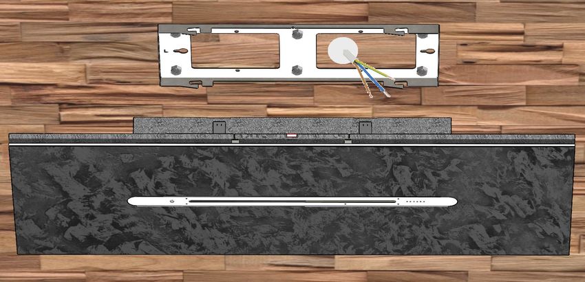
DE

Sehr geehrte Kundin,
sehr geehrter Kunde,

vielen Dank für Ihre Entscheidung zum Kauf einer GUTMAN Dunstabzugshaube !

Bitte lesen Sie nachfolgende Informationen und Erläuterungen zum sachgemäßen
Gebrauch Ihrer neuen Haube aus dem Hause GUTMAN vor der ersten Inbetriebnah-
me sorgfältig durch. Bitte beachten Sie gleichfalls unsere Bedienungs- und Monta-
geanleitung sowie die darin enthaltenen Reinigungsempfehlungen, so dass Sie lange
Freude an Ihrem Gerät haben.

Die angegebenen Daten in dieser Montagesanleitung dienen alleine der Produktbeschreibung. Eine Aussage
über eine bestimmte Beschaffenheit oder Eignung für einen bestimmten Einsatzzweck kann aus unseren
Angaben nicht abgeleitet werden. Die Angaben entbinden den Verwender nicht von eigenen Beurteilungen
und Prüfungen. Es ist natürlich zu beachten, dass unsere Produkte einem natürlichen Verschleiß- und
Alterungsprozess unterliegen.
Alle Rechte liegen bei der GUTMANN GmbH, auch für den Fall von Schutzrechtsanmeldungen.
Jede Verfügungsbefugnis, wie Kopie- und Weitergaberecht, liegt bei uns.

Auf der Titelseite ist eine Beispielkonfiguration abgebildet. Das ausgelieferte
Produkt kann daher von der Abbildung abweichen.
Alle Abbildungen in diesem Dokument sind Symbolbilder und können vom vor
liegenden Produkt abweichen.

Die Orginalbedienungsanleitung wurde in deutscher Sprache erstellt.

2
DE

                             INHALTSVERZEICHNIS
                                                                            SEITE
VORBEMERKUNGEN
     Warnhinweise und Symbole :                                               4
     Sicherheitshinweise :                                                  5-6
     Montagezubehör / Montagematerial / Werkzeug :                            7

PRODUKTBESCHREIBUNG
     Produktkomponenten :                                                     8
     Maßzeichnungen :                                                         9

MONTAGEANLEITUNG
     Montagevorbereitung :                                                   10
     Deckenmontage :                                                         11

ALLGEMEINE THEMEN
     Reinigung :                                                             64
     Entsorgung :                                                            64
     Umwelthinweise :                                                        64

Technische Daten und Anschlusswerte
Abmaße:                      1500 x 600 x 167 mm
Gewicht:                     ca.: 47 kg
Leuchtkörper Kochfeld:       LED - tunable white
Ambient Beleuchtung:         In Acryl-Glasplatte
Steuerungen:                 Fernbedienung und Wipptaster
Lüftungstechnik:             Randabsaugung
Volumenstrom Lüfter:         ca.: 600m³/h freiblassend
Fettfilter:                  Aluminium - Kunststoffgestrick ( TZ4807 )
Geruchsfilter:               Aktivkohle - Feinstaubfilter-Flies ( TZ463 )
Spannung:                    230 V ~
Leistung:                    ca.: 170 Watt

                                                                                    3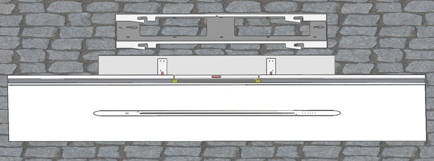
DE

                       VORBEMERKUNGEN
Warnhinweise und Symbole
In dieser Anleitung stehen Warnhinweise vor einer Handlungsanweisung, bei der die
                  Gefahr von Personen- oder Sachschäden besteht.
           Maßnahmen zur Gefahrenabwehr müssen eingehalten werden.

 WARN-
                                    BEDEUTUNG
ZEICHEN

            Warnung vor einer Gefahrenstelle !
            Bezeichnet mögliche gefährliche Situationen. Das Nichtbeachten der
            Warnhinweise kann zu Personen- und / oder Sachschäden führen.

            Warnung vor gefährlicher elektrischer Spannung !
            Bezeichnet mögliche Gefahren durch Elektrizität. Das Nichtbeachten
            der Warnhinweise kann zu Tod, Verletzungen und / oder Sachschä-
            den führen.

            Warnung vor heißer Oberfläche !
            Bezeichnet mögliche Gefahren durch hohe Oberflächentemperatu-
            ren. Das Nichtbeachten der Warnhinweise kann zu Personen und / o-
            der Sachschäden führen.

            Warnung vor Handverletzungen !
            Bezeichnet mögliche Gefahren durch bewegliche und rotierende Tei-
            le. Das Nichtbeachten der Warnhinweise kann zu Personenschäden
            führen.

            Warnung vor giftigen Stoffen !
            Bezeichnet mögliche Gefahren durch einatmen von giftigen Gasen.
            Das Nichtbeachten der Warnhinweise kann zum Tode oder schweren
            Vergiftungen führen.

            Warnung vor feuergefährlichen Stoffen !
            Bezeichnet mögliche Gefahren durch Brandgefahr. Das Nichtbeach-
            ten der Warnhinweise kann zu Tod, Verletzungen und Sachschäden
            führen.

            Warnung vor Schnittverletzungen durch Glasbruch !
            Bezeichnet mögliche Gefahren durch scharfe Kanten. Das Nichtbe-
            achten der Warnhinweise kann zu Schnittverletzungen und Perso-
            nenschäden führen.

4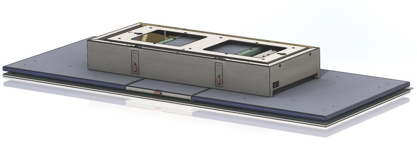
DE

Sicherheitshinweise
Montage, Anschluss, Inbetriebnahme und Reparatur dürfen nur von einer Fachkraft
durchgeführt werden. Diese Fachkraft kann die geeignete Befestigung und Abluftfüh-
rung der Dunstabzugshaube bestimmen. Die Befestigung muss für das Gewicht der
Dunstabzugshaube und die Belastung des Untergrunds geeignet sein. Die Auszugs-
werte der mitgelieferten Dübel beachten. Diese haben in Abhängigkeit vom Untergrund
folgende Werte:
Höchste empfohlene Lasten eines Einzeldübels :                Dübel Ø 8 mm:
Beton ≥ C20/25                                                   0,60 KN
Vollziegel ≥ Mz 12                                               0,50 KN
Kalksandvollstein ≥ KS 12                                        0,55 KN
Bei anderen unsicheren Untergründen ist für die sichere Montage der Dunstabzugs-
haube ein Fachmann für Bauangelegenheiten, z.B. ein Statiker oder Architekt, zu be-
fragen.
Verletzungsgefahr!
Fertigungsbedingt können sich im Haubenkörper scharfe Kanten befinden.
Schutzhandschuhe sind bei der Montage zu tragen.
Installation
Das Gerät darf nur von einem autorisierten Fachmann unter Beachtung aller einschlä-
gigen Vorschriften der Stromversorgungsunternehmen sowie der Bauverordnungsvor-
schriften der Länder angeschlossen werden. Beachten Sie bei der Montage die ent-
sprechende Anleitung! Beschädigte Geräte dürfen nicht in Betrieb genommen werden.
Defekte Teile müssen durch GUTMANN Originalteile ersetzt werden. Reparaturen dür-
fen nur durch autorisiertes Fachpersonal durchgeführt werden.
Gefahr durch elektrischen Schlag
Die Netzspannung muss mit den Angaben auf dem Typenschild übereinstimmen. Die-
ses befindet sich im Bereich des Filters im Haubeninneren. Die Dunstabzugshaube nur
an eine vorschriftsmäßig installierte Schutzkontaktsteckdose anschließen. Die Steck-
dose muss nach der Montage leicht erreichbar sein, um die Dunstabzugshaube bei Be-
darf von der Netzspannung trennen zu können. Bei Festanschluss (z.B. wenn eine ent-
sprechende Steckdose nicht vorhanden ist) darf die Dunstabzugshaube nur von einer
Elektrofachkraft an die Netzspannung angeschlossen werden. Für den Festanschluss
muss die Dunstabzugshaube an einen Einzelstromkreis mit Trennvorrichtung ange-
schlossen werden. Als Trennvorrichtung gelten Schalter mit einer Kontaktöffnung von
mindestens 3 mm und allpoligen Schaltern, z.B. LS-Schalter und Schütze. Vor den Ar-
beiten am elektrischen Anschluss der Dunstabzugshaube den Netzstromkreis / die
Netzstromkreise abschalten. Vor dem Bohren von Befestigungslöchern prüfen, dass
keine elektrischen Leitungen durch das Bohren beschädigt werden können. Der Elekt-
roanschluss muss so vorbereitet werden, dass die Dunstabzugshaube damit einfach
angeschlossen werden kann. Dabei müssen örtliche Bestimmungen eingehalten wer-
den.
Feuerstätte für feste Brennstoffe
Über einer Feuerstätte für feste Brennstoffe, von der eine Brandgefahr (z.B. Funken-
flug) ausgehen kann, ist die Montage der Dunstabzugshaube nur dann zulässig, wenn
die Feuerstätte eine geschlossene, nicht abnehmbare Abdeckung hat.

                                                                                  5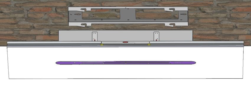
DE

Mindestabstand zur Kochstelle
Die optimale Absaugleistung erreichen Sie, wenn die Haube in einer Höhe von min.
550mm ab Oberkante Arbeitsplatte montiert wird. Bei Gas sind es min. 650mm. Um
Kondensatbildung zu verhindern muss eine Rückstauklappe direkt am Luftaustritt au-
ßen montiert werden. Bei Gas-Kochgeräten sind jeweils die gültigen Einbauvorschrif-
ten und die Einbauhinweise der Gas-Gerätehersteller zu beachten. Über Gas-
Kochstellen ist die Montage der Dunstabzugshaube bei einem Mindestabstand von
650 mm nur zulässig, wenn folgende Nennwärmebelastungen (Hs) nicht überschritten
werden:
Gas-Herde
Belastung einer Kochstelle max. 3,0 KW
Belastung aller Kochstellen max. 8,3 KW
Belastung des Backofens max. 3,9 KW
Gas-Kochmulden
Belastung einer Kochstelle max. 3,9 kW
Belastung aller Kochstellen max. 11,3 kW
Abstände:
Max.: Raumhöhe 2,7m
Bei C - Umluftversion kann es bei hohen Lüfterstufen zu Luftverwirbelungen kommen.
Wir empfehlen daher 2m Mindestabstand zwischen Umluftöffnungen und Wänden !
Anschluss Stromnetz
Überprüfen Sie, ob die angegebene Nennspannung des Gerätes mit der örtlichen
Netzspannung übereinstimmt. Eine falsche Einstellung führt zur Beschädigung bzw.
Zerstörung des Gerätes.
Überprüfen Sie vor dem Betrieb, ob alle Kabel und Leitungen einwandfrei und unbe-
schädigt sind. Achten Sie insbesondere darauf, dass die Kabel keine Knickstellen auf-
weisen, um Ecken herum nicht zu kurz verlegt worden sind und keine Gegenstände
auf den Kabeln stehen. Achten Sie weiterhin darauf, dass alle Steckverbindungen fest
sitzen. Eine fehlerhafte Schirmung oder Verkabelung gefährdet Ihre Gesundheit
(elektrischer Schlag) und kann andere Geräte zerstören. Geräte mit Netzstecker wer-
den mit einer sicherheitsgeprüften Netzleitung des Einsatzlandes ausgerüstet und dür-
fen nur an eine vorschriftsmäßig geerdete Schutzkontakt-Steckdose angeschlossen
werden, andernfalls droht elektrischer Schlag. Stellen Sie sicher, dass die Steckdose
am Gerät oder die Schutzkontakt-Steckdose der Hausinstallation frei zugänglich ist,
damit im Notfall oder bei Service– bzw. Wartungsarbeiten das Netzkabel aus der
Steckdose gezogen werden kann.
Transport, Auspacken, Aufstellen
Wenn das Gerät aus kalter Umgebung in den Betriebsraum ge-
bracht wird, kann Betauung auftreten. Bitte warten Sie bis das Ge-
rät temperaturangeglichen und absolut trocken ist, bevor Sie es in
Betrieb nehmen. Die Akklimatisationszeit ist abhängig von Tempe-
raturdifferenz und Gerät sowie dessen Aufbau. Sie sollte aber min-
destens 12 Stunden betragen.
Bitte tragen Sie während der Montage Schutzhandschuhe, um ei-
ne Verletzungsgefahr auszuschließen. Vor der Montage der Hau-
be benötigte Werkzeuge herrichten. Für die Montage der Haube
sind bauseitige Voraussetzungen für eine reibungslose Montage
der      Haube     zu    schaffen,    Küchengeräte      abdecken.
Geeignete Abluftführung in der Decke vorbereiten, Zwischendecke
öffnen, Durchbrüche erstellen etc..
Vor dem Bohren in der Wand, sicherstellen das keine dahinterlie-
genden Leitungen beschädigt werden.

6
DE

Bitte unbedingt beim Heraus- und Anheben mit den Fingern in den Zuluftschlitz
          greifen um ein Verbiegen der Acrylglasfront zu vermeiden !

Montagezubehör / Montagematerial / Werkzeug
6x Dübel S8
6x Scheibe DIN 125 A6,4
6x Schraube 6x45 DIN 571
2x Schraube M5x12 DIN 912
3x Klemme

                                                                            7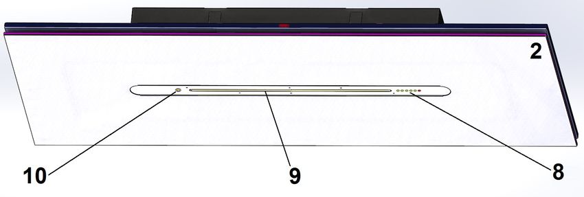
DE
PRODUKTBESCHREIBUNG
Komponenten
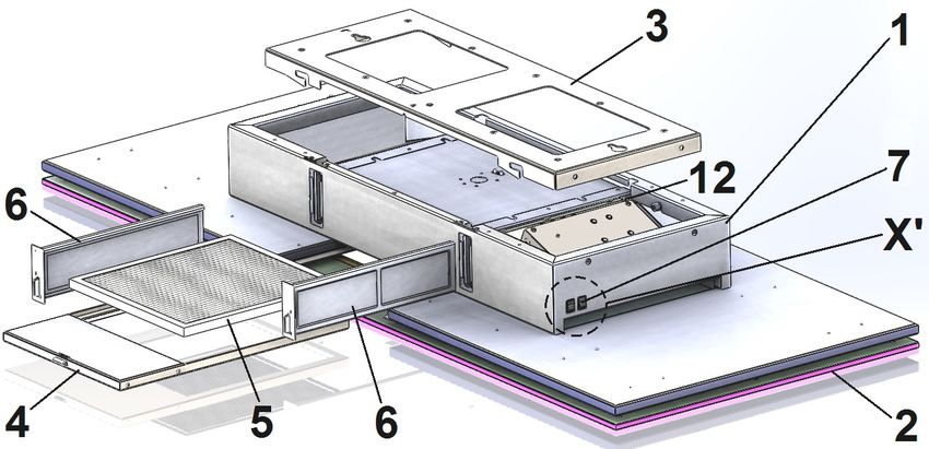
1 Haubenkörper
2 Acrylglasfront ( mit Ambientbeleuchtung )
Detail X‘
3 Montagerahmen
4 Fettfilter-Einschub
5 Fettfilter ( TZ4807 )
6 Aktivkohle-Geruchsfilter ( TZ463 )
7 Bedienelemente ( Schalter )
8 Leistungsanzeige LED
9 Beleuchtung 2700 - 6500K
10 IR - Sensor
11 IR - Fernbedienung
12 Stromanschluss (7a) Wipptaster (7b) Kippschalter
8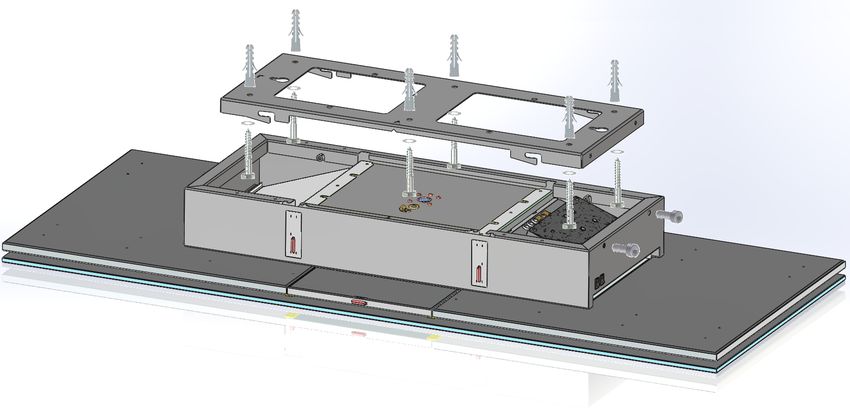
DE
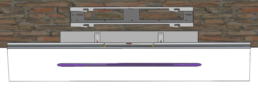
Maßzeichnungen
L - Markierung Zentrum V - Markierung ( Bedienerseite )
9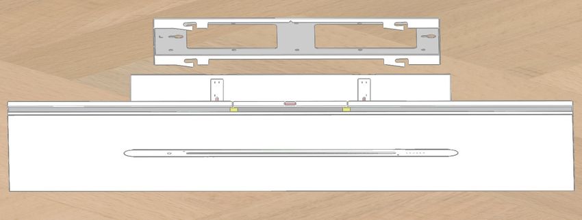
DE

                        MONTAGEANLEITUNG
Montagevorbereitung
Allgemein:
Bevor die Dunstabzugshaube unser Werk verlässt wird diese einem ausführlichen
Funktionstest unterzogen.
Die Decken-Dunstabzugs-Haube APILAR wird komplett im Endzustand installiert aus-
geliefert. Zur Deckenmontage müssen die Hinweise auf den folgenden Seiten beachtet
werden.
1. Die Dunstabzugshaube vorsichtig mit 2 Personen aus der Verpackung mit den Fin-
    gern im Zuluftschlitz entnehmen und mittels Unterlage auf den Montagelift legen. 2
    Sicherungsschrauben lösen und Montageblech herausziehen.
2. Anschließend Montageort an der Decke vorbereiten. Um eine optimale Abzugska-
    pazität zu erreichen, muss die Anordnung der Haube mittig über dem Kochfeld
    sein. Die Mitte der Haube mittels einem Lot an der Decke anzeichnen.
3. Befestigungsbohrungs - Abmaße des Montagerahmens auf die Decke übertragen -
    15mm Versatz beachten ( Masszeichung ) .
4. Position für Kabelanschluss bzw. Klemmendose bestimmen. Sollte im Bereich der
    großen Öffnungen des Montagerahmens angebracht werden.

                                                     mittig auf „ V “ - Kennzeichnung
                                                                ausgerichtet

5. 6 Bohrungen 8 x >60 mm gemäß Maßzeichnung in die Decke bohren und für das
   Mauerwerk geeignete Dübel einsetzen. ( hierfür Betonbohrer 8mm )
6. Elektrischen Anschuss erstellen.

10
DE
Deckenmontage
7. Montagerahmen entlang der Bohrungen an die Decke halten und Befestigungs-
schrauben einschrauben.
8. APILAR mit Montagelift in geringem Abstand unter der Decke anheben und mit
dem Stromkabel und den Klemmen verbinden. Kabel aufrollen.
9. Bis an die Decke anheben und nach links in Halteschlitze „ Y “ einschieben.
10. Sicherungsschrauben eindrehen.
11. Spannungsversorgung zum Netz wiederherstellen. Funktionstest gemäß Bedie-
nungsanleitung durchführen.
12. Reinigen.
11EN Dear customer, Thank you for choosing a GUTMAN extractor hood ! Please carefully read the following information and explanations on the proper use of your new GUTMAN hood before using the appliance for the first time. Please also read our operating and installation instructions as well as the cleaning recommenda- tions to ensure that you enjoy many years of service from your appliance. The data contained in these operating instructions is used for descriptive purposes only. No statement regarding a particular quality or suitability for a specific application can be implied from the information provided. The information provided does not relieve the user of the responsibility to carry out their own assessments and checks. It should be noted that our products are subject to a natural process of ageing and wear. All rights are reserved by GUTMANN GmbH, also in the case of applications for industrial property rights. All rights of disposal, such as the right to create copies or circulation rights rest with us. The title page shows a sample configuration. The product supplied may therefore differ from the illustration. The operating instructions were originally drafted in German. 12
EN

                            TABLE OF CONTENTS
                                                                               PAGE

PRELIMINARY REMARKS
    Warnings and symbols:                                                        14
    Safety instructions :                                                      15 - 16
    Mounting accessories / Mounting material / Tools :                           17

ASSEMBLY INSTRUCTIONS
    Product components :                                                         18
    Dimension drawings :                                                         19

ASSEMBLY INSTRUCTIONS
    Assembly preparation :                                                       20
    Ceiling mounting :                                                           21

GENERAL TOPICS
    Cleaning :                                                                   64
    Disposal :                                                                   64
    Environmental information :                                                  64

Technical data and connected loads

Dimensions:                         1500 x 600 x 167 mmm
Weight:                             approx.: 47 kg
Luminous body:                      LED - tunable white
Ambient lighting:                   In acrylic glass plate
Controls:                           Remote control and rocker switch
Ventilation technology:             Edge extraction
Volume flow fan:                    approx.: 600m³/h free blowing
Grease filter:                      Aluminium- plastic knitted fabric ( TZ4807 )
Odour filter:                       Activated carbon fine dust filter fleece ( TZ463 )
Voltage:                            230 V ~
Power:                              approx.: 170 Watt

                                                                                         13
EN
PRELIMINARY NOTES
Warning notice and symbols
Warnings in these operating instructions are placed in front of an instruction that may
result in personal injury or property damage.
Measures to avert a hazard must be observed.
WARN-
ING- MEANING
SIGNS
Warning of a danger spot !
Indicates potentially dangerous situations. Failure to observe the warn-
ing notices may result in personal injury and/or damage to property.
Warning of dangerous voltage !
Indicates possible hazards due to electricity. Failure to observe the
warnings may result in death, injury and/or property damage.
Warning of hot surface !
Indicates possible hazards due to high surface temperatures to the
other side. Failure to observe the warnings may result in personal inju-
ry and/or damage to property.
Warning of hand injuries !
Indicates possible hazards due to moving and rotating parts. Non-
observance of the warnings can result in personal injury.
Warning of toxic substances !
Indicates possible dangers due to inhalation of toxic gases. Failure to
observe the warnings may result in death or serious poisoning.
Warning of flammable substances !
Indicates possible dangers due to fire hazard. Failure to observe the
warnings may result in death, personal injury or property damage.
Warning of cuts due to glass breakage !
Indicates possible hazards due to sharp edges. Failure to observe the
warnings may result in cutting injuries and personal injury.
14EN
Safety instructions
Installation, connection, startup and repairs may be carried out by technicians only.
Technicians can specify a suitable attachment and exhaust air conduction for the
extractor hood. The attachment must be suitable for the weight of the extractor hood
and for the load on the wall. Observe the pullout values of the supplied wall plugs. The-
se have the following values depending on the wall:
Highest recommended loads of a single anchor : Ø 8mm dowels:
Concrete ≥ C20/25 0,60 KN
Brick ≥ Mz 12 0,50 KN
Solid calcium silicate brick ≥ KS12 0,55 KN
If the wall is made of other uncertain materials, consult a building specialist, e.g. a
structural engineer or an architect to ensure that the extractor hood can be installed
securely.
Risk of injury
The hood structure may have sharp edges caused by the manufacturing process.
Wear protective gloves during installation.
Installation
The appliance may only be installed and connected by an authorised technician obser-
ving all relevant regulations of the electric utility companies and the applicable building
regulations. During installation, observe the relevant instructions !
Damaged appliances may not be put into operation. Defective parts must be replaced
with genuine parts.
Repairs should only be carried out by authorised technical staff.
Risk of electric shock
The mains voltage must correspond with the specifications on the rating plate. The ra-
ting plate is situated near the filters inside the hood. Connect the extractor hood to a
correctly installed earthed socket only. The socket must be easily accessible following
installation so that the extractor hood can be isolated if required. If the extractor hood is
to be permanently connected (e.g. if there is no appropriate socket), it may be connec-
ted to the mains by an electrician only. If the extractor hood is to be permanently
connected, it must be connected to a single electric circuit with disconnector. Switches
with a contact opening of at least 3 mm and all-pole switches, e.g. LS switches and
contactors, are regarded as disconnectors. Before connecting the extractor hood to the
power supply, disconnect the mains circuit(s). Before drilling fixing holes, ensure that
there are no electric cables which could be damaged by the drilling. When preparing
the power supply connection, ensure that the extractor hood can be connected without
difficulty. Observe local regulations.
Solid fuel fireplaces
The cooker hood may only be installed above a fireplace for solid fuels from which the-
re is a risk of fire (e.g. flying sparks) if the fireplace has a closed, non-removable cover.
15EN Minimum distance from cooking appliance Optimum extraction performance is achieved when the hood is mounted at a height of at least 550 mm from the top edge of the worktop. For gas, it is also min. 650mm. In order to prevent condensate formation, a backwater flap must be mounted directly on the outside of the air outlet. For gas cooking appliances, the applicable installation re- gulations and the installation instructions of the gas appliance manufacturer must be observed. The cooker hood may only be installed above gas cooking zones at a mini- mum distance of 650 mm if the following nominal heat loads (Hs) are not exceeded: Gas stoves Load from one gas ring max.3.0 kW Load from all gas rings max.8.3 kW Load from oven max.3.9 kW Gas hobs Load from one gas ring max.3.9 kW Load from all gas rings max.11.3 kW Spacing: Max. room height 2,7m With the C - circulating air version, air turbulence can occur at high fan speeds. We therefore recommend a minimum distance of 2m between recirculation openings and walls! Connection to power supply Check that the rated voltage of the device corresponds to the local mains voltage. In- correct setting will damage or destroy the device. Before operation, check whether all cables and wires are faultless and undamaged. In particular, make sure that the cables have no kinks, have not been laid too short around corners and that there are no objects on the cables. Furthermore, make sure that all plug connections are tight. Faulty shielding or wiring endangers your health (electric shock) and can destroy other equipment. Devices with a mains plug are equipped with a safety-tested mains cable from the country of use and must only be connected to a properly earthed earth contact socket, otherwise there is a risk of electric shock. Make sure that the socket at the device or the earth contact socket of the house installation is freely accessible so that the mains cable can be disconnected from the socket in an emergency or during service or maintenance work. Transport, unpacking, installation Condensation may occur if the appliance is brought into the instal- lation site from a cold environment. Please wait until the appliance has adjusted to the temperature and is completely dry before ope- rating it. The acclimatization period depends on the temperature difference and the type and design of the appliance. However, it should be at least 12 hours. Please wear protective gloves during installation to avoid the risk of injury. Prepare the necessary tools before mounting the hood. For the installation of the hood, on-site requirements must be met to ensure smooth installation of the hood and kitchen appliances must be covered. Prepare a suitable exhaust air duct in the ceiling, open the false ceiling, create openings, etc.. Before drilling in the wall, make sure that no pipes behind it are da- maged. 16
EN

Please make sure that you reach into the suction slot with your fingers when lif-
        ting out and in order to avoid bending the acrylic glass front !

Mounting accsessories / mounting materials / tools

6x Dowel S8
6x Screw 6x45 DIN 571
6x Washer DIN 125 A6,4
2x Washer Ø6,4 - Ø16mm
2x Screw M5x12 DIN 912
3x Clamp

                             Assembly Tools
                             Assembly tools

                                                                               17
EN
PRODUCT DESCRIPTION
Components
1 Hood body
2 Acrylic glass front ( with ambient lighting ) Detail X‘
3 Mounting frame
4 Grease filter insert
5 Grease filter ( TZ4807 )
6 Activated carbon odour filter ( TZ463 )
7 Operating elements ( switches )
8 Power indicator LED
9 Lighting 2700 - 6500K
10 IR - Sensor
11 IR remote control
12 Electrical connection (7a) Rocker switch (7b) Toggle switch
18EN
Dimensional drawing
L - Marking Center V - Marking / user side
19EN
ASSEMBLY INSTRUCTION
Assembly preparation
General:
Before the cooker hood leaves our factory, it undergoes a detailed functional test.
The APILAR ceiling cooker hood is delivered completely installed. For ceiling installati-
on, the instructions on the following pages must be observed.
1. Carefully remove the cooker hood with 2 persons from the packaging with your fin-
gers in the supply air slot and place it on the assembly lift using a base. Loosen 2
locking screws and pull out the mounting plate.
2. Then prepare the mounting location on the ceiling. To achieve optimum extraction
capacity, the hood must be positioned centrally above the hob. Mark the centre of
the hood on the ceiling using a plumb line.
3. Mounting hole - Transfer the dimensions of the mounting frame to the ceiling - Note
the 15mm offset ( dimension drawing ) .
4. Determine position for wireing or terminal box. Should be installed in the area of the
large opening of the mounting frame.
centered on " V " - marking
5. Drill six 8 x >60 mm holes in the ceiling according to the dimensioned drawing and
insert dowels suitable for the masonry. ( for this concrete drill 8mm )
6. Make the electrical connection.
20EN
Ceiling mounting
7. Hold the mounting frame to the ceiling along the holes and screw in the fixing
screws.
8. Lift the APILAR with the mounting lift at a small distance below the ceiling and
connect it to the power cable and the terminals. Roll up the cable.
9. Lift it up to the ceiling and slide it into the holding slots " Y ".
10. Screw in the locking screws.
11. Connect the power supply to the mains. Carry out a function test according to the
operating instructions.
12. Cleaning.
21FR Chère cliente, Cher client, Nous vous remercions pour l’achat de votre hotte aspirante GUTMAN ! Avant la première utilisation, nous vous conseillons de bien lire les informations et ex- plications ci-dessous pour une utilisation conforme de votre nouvelle hotte GUTMAN. Merci d’également de respecter notre mode d’emploi et nos instructions de montage, ainsi que nos conseils de nettoyage, afin de pouvoir profiter longuement de votre hotte. Les données contenues dans ce mode d'emploi ne sont fournies qu'à titre de description du produit. Nos données ne permettent pas d'établir une déclaration sur une certaine condition ou adéquation à une certaine fi- nalité. L'information ne libère pas l'utilisateur de ses propres évaluations et tests. Il est à noter que nos produits sont soumis à un processus naturel d'usure et de vieillissement. Tous les droits sont réservés par GUTMANN GmbH, y compris pour les demandes de droits de propriété indust- rielle. Nous avons tous les pouvoirs de disposition, tels que le droit de copier et de transmettre. Un exemple de configuration est présenté sur la page de titre. L'équipe livrée. Le produit peut donc différer de l'illustration. Le mode d'emploi original a été rédigé en allemand. 22
FR

                                      SOMMAIRE
                                                                                     PAGE

REMARQUES PRÉLIMINAIRES
    Avertissements et symboles :                                                       24
    Consignes de sécurité :                                                          25 - 26
    Accessoires de montage / Matériel de montage / Outils :                             7

DESCRIPTION DU PRODUIT
    Composants :                                                                       28
    Cotes d'encombrement :                                                             29

INSTRUCTIONS DE MONTAGE :
    Voorbereiding van de montage :                                                     30
    Plafondbevestiging :                                                               31

SUJETS GÉNÉRAUX
    Nettoyage :                                                                        65
    Élimination :                                                                      65
    Informations sur l'environnement :                                                 65

Caractéristiques techniques et charges raccordées

Dimensions :                                  1500 x 600 x 165 mmm
Poids :                                       Environ 47 kg
Plaque de cuisson lumineuse pour le corps :   LED - blanc accordable 2700 - 5600K
Éclairage ambiant :                           En plaque de verre acrylique 2700 + 5600K
Contrôles :                                   Télécommande et interrupteur à bascule
                                              ("marche d'urgence")
Technologie de ventilation :                  extraction de bord
Ventilateur de débit :                        env. 600 m³/h
Filtre à graisse :                            Tricot d'aluminium-plastique ( TZ4807 )
Filtre à odeurs :                             Tissu filtrant pour poussières fines de char-
                                              bon actif ( TZ463)
Tension :                                     230 V ~
Le pouvoir :                                  Environ 170 Watt

                                                                                            23
FR
REMARQUES PRÉLIMINAIRES
Avertissements et symboles
Ce manuel contient des mises en garde devant des instructions qui peuvent entraîner
des blessures corporelles ou des dommages matériels.
Les mesures de prévention des dangers doivent être respectées.
SIGNAL DE
AVERTIS- SIGNIFICATION
SEMENT
Mise en garde contre un endroit dangereux !
Désigne des situations potentiellement dangereuses.
Le non-respect de cette mise en garde peut entraîner des blessures
et/ou des dégâts matériels.
Mise en garde contre une tension électrique dangereuse !
Signale un éventuel danger dû à l'électricité.
Le non-respect de cette mise en garde peut entraîner des blessures
graves voire mortelles et/ou des dégâts matériels.
Mise en garde contre une surface chaude !
Signale un éventuel danger dû à une surface chaude.
Le non-respect de cette mise en garde peut entraîner des blessures
et/ou des dégâts matériels.
Avertissement relatif au risque de blessures aux mains !
Signale un éventuel danger dû à des pièces mobiles ou en rotation.
Le non-respect de ces mises en garde peut entraîner des dommages
corporels.
Mise en garde contre les substances toxiques !
Signale un éventuel danger dû à l’inhalation de gaz toxiques.
Le non-respect de cette mise en garde peut entraîner de graves cas
d'empoisonnement, voire la mort.
Mise en garde contre les substances inflammables !
Signale un éventuel danger dû à un risque d’incendie.
Le non-respect de cette mise en garde peut entraîner des blessures
graves voire mortelles ainsi que des dégâts matériels.
Mise en garde contre les coupures dues à des bris de glace !
Signale un éventuel danger dû à des bords tranchants.
Le non-respect de ces mises en garde peut entraîner des dommages
corporels et des coupures.
24FR
Consignes de sécurité
Seul un personnel qualifié est autorisé à procéder au montage, aux branchements, à la
mise en service et aux réparations. Ce spécialiste détermine la fixation et la conduite
d’évacuation adaptées pour la hotte aspirante. Le type de fixation doit tenir compte du
poids de la hotte et de la charge du support. Respectez les valeurs de portée de che-
villes fournies. Celles-ci possèdent les valeurs ci-dessous en fonction du type de sup-
portcheville:
Charges maximales recommandées d'une ancre unique : Cheville Ø 8 mm:
Béton ≥ C20/25 0,60 KN
Brique pleine ≥ Mz 12 0,50 KN
Brique de sable de chaux solide ≥ KS 12 0,55 KN
Pour tout autre support non stable, veuillez demander l’avis d’un expert en bâtiments
(par ex. un architecte ou un staticien) afin de garantir le montage sûr de la hotte.
Risque de blessure !
Le carter de la hotte peut présenter des arrêtes vives dues à sa fabrication. Portez des
gants de sécurité lors du montage!
Installation
L’appareil ne peut être raccordé que par un spécialiste autorisé, travaillant dans le
respect de toutes les prescriptions correspondantes du fournisseur d’électricité et des
prescriptions nationales pour les chantiers. Lors du montage, suivre les instructions de
montage correspondantes !
Des appareils endommagés ne peuvent être mis en service. Toutes les pièces défec-
tueuses doivent être remplacées par des pièces d’origine. Les réparations ne peuvent
être exécutés que par des personnes spécialisées et autorisées à cet effet.
Risque d‘électrocution
La tension d’alimentation doit correspondre avec celle de la plaque signalétique située
à l’intérieur de la hotte au niveau des filtres.
Branchez la hotte uniquement à une prise de terre et conformément aux réglementati-
ons en vigueur. Vous devez pouvoir atteindre facilement la prise une fois la hotte mon-
tée, afin de pouvoir la débrancher si nécessaire. Dans le cas d’un branchement fixe (p.
ex. si aucune prise de terre n’est présente), seul un électricien est autorisé à raccorder
la hotte au courant électrique. Dans ce cas, ’électricien doit brancher la hotte à un cir-
cuit de courant simple équipé d’un disjoncteur. Les interrupteurs avec une ouverture
d’au moins 3 mm et ceux tous pôles (par ex. les interrupteurs LS) conviennent ici com-
me disjoncteur. Coupez le courant avant toute intervention électrique sur la hotte.
Avant de percer les fixations, assurez-vous qu’aucun câble électrique ne soit endom-
magé. Réalisez le branchement électrique de telle manière à pouvoir raccorder facile-
ment la hotte. Respectez les directives locales.
Foyer pour combustibles solides
Pour éviter tout risque d’incendie (p. ex. des flammèches), le montage de la hotte au-
dessus d‘un foyer pour combustibles solides est uniquement autorisé si le foyer est fer-
mé par un couvercle non amovible.
25FR Distance minimum à la cuisinière Vous obtenez un débit d’air à la buse maximum si vous montez la hotte à une hauteur de 550 mm à partir du côté supérieur du plan de travail. Pour le gaz, la hauteur confor- me est de 650 mm. Pour éviter la condensation, un clapet anti-retour doit être monté à l’extérieur sur le conduit d’aération. Distance minimum entre des foyers electriques et l’arete inferieure de la hotte aspirante: 550 mm. Appareils de cuisson au gaz Veuillez respecter les prescriptims et consignes de montage appiicables, publiees par les fabri- cants de ces appareils. Le montage de la hotte aspirante ä la distance minimum de 650 mm au-dessus de foyers au gaz (voir figure) est admis ä condition de ne pas de- passer les charges thermiques nominales ci-dessous: Poêles à gaz Charge sur une zone de cuisson max. 3,0 KW Charge sur toutes les zones de cuisson max. 8,3 KW Charge max. du four 3,9 KW plaques de cuisson au gaz Charge d'une place de cuisson max. 3,9 KW Charge sur toutes les zones de cuisson max. 11,3 KW Espacement : Hauteur max. de la pièce 2,7m Des turbulences d'air peuvent se produire dans les étages élevés avec les versions à circulation d'air en C ! Raccordement à l'alimentation électrique Vérifier que la tension nominale de l'appareil correspond à la tension secteur locale. Un mauvais réglage endommagera ou détruira l'appareil. Avant la mise en service, vérifiez que tous les câbles et fils sont en parfait état et intacts. Veillez en particulier à ce que les câbles ne soient pas pliés, qu'ils ne soient pas trop courts dans les coins et qu'il n'y ait pas d'objets sur les câbles. De plus, as- surez-vous que toutes les connexions sont bien serrées. Un blindage ou un câblage défectueux met en danger votre santé (choc électrique) et peut détruire d'autres équipements. Les appareils munis d'une fiche secteur sont équipés d'un câble secteur de sécurité du pays d'utilisation et ne doivent être raccordés qu'à une prise de terre de mise à la terre appropriée, sinon il y a risque de choc électrique. Veillez à ce que la pri- se de l'appareil ou la prise de terre de l'installation domestique soit librement accessib- le afin que le câble d'alimentation puisse être débranché de la prise en cas d'urgence ou lors de travaux d'entretien ou de maintenance. Transport, déballage, installation Si l’appareil a été entreposé dans un lieu froid, de la buée peut se former dessus. Attendre que l’appareil soit parfaitement à température et sec avant de le mettre en service. La durée de mi- se en température dépend de la différence de température et de la constitution de l’appareil. Un minimum de 12 heures est toute- fois conseillé. Veuillez porter des gants de protection pendant l'installation afin d'éviter tout risque de blessure. Avant de monter le capot, prépa- rer les outils nécessaires. Pour l'installation de la hotte, les exigences du chantier doivent êt- re satisfaites pour une installation en douceur de la hotte, les ap- pareils ménagers doivent être couverts. Préparer des conduits d'évacuation d'air appropriés, si néces- saire ouvrir le faux-plafond, les cloisons, le bloc cuisine, créer des ouvertures etc.... 26
FR

 Lors du levage et du desserrage, veillez à passer les doigts dans la fente d'ali-
       mentation en air afin de ne pas plier la façade en verre acrylique !

Accessoires de montage / Matériel de montage / Outils

6x Cheville S8
6x Laveuse DIN 125 A6.4
6x Vis 6x45 DIN 571
2x Vis M5x12 DIN 912
3x Terminal

                            Outil d'assemblage

                                                                                 27
FR
DESCRIPTION DU PRODUIT
Constituants
1 Corps de capuche
2 Façade en verre acrylique
(avec éclairage d'ambiance)
3 Cadre de montage Detail X‘
4 Cartouche filtrante à graisse
5 Filtre à graisse ( TZ4807 )
6 Filtre d'odeur à charbon actif ( TZ463)
7 Eléments de commande
(interrupteur à bascule)
8 Indicateur d'alimentation LED
9 Éclairage 2700 - 6500K
10 Infrarouge - Capteur
11 Télécommande Infrarouge
12 Connexion d'alimentation avec commande (7a) Interrupteur à bascule
(7b) Interrupteur à bascule
28FR
Schémas d'encombrement
L - marquage centre V - marquage (côté commande)
29FR
INSTRUCTIONS DE MONTAGE
Préparation du montage
Généralités :
Avant sa sortie d’usine, la hotte aspirante est soumise à un essai de fonctionnement
approfondi.
La hotte aspirante APILAR intégrée au plafond est fournie à l’état final, complètement
montée. Pour un montage au plafond, les instructions figurant sur les pages suivantes
doivent être respectées.
1. À deux personnes, retirer avec précaution la hotte aspirante de son emballage en
plaçant les doigts dans la fente d’air et la poser sur le monte-charge en utilisant un
support. Desserrer les 2 vis de blocage et retirer la plaque de montage.
2. Préparer ensuite l’emplacement de montage au plafond. Afin d’optimiser la capacité
d’aspiration, la hotte doit être placée au centre, au-dessus de la table de cuisson.
Marquer au plafond le centre de la hotte à l’aide d’un fil à plomb.
3. Reporter les dimensions des trous de fixation du cadre de montage au plafond –
tenir compte du décalage de 15 mm (dessin coté).
4. Déterminer la position du raccord de câble ou de la boîte à bornes. Doit être installé
dans la zone des grandes ouvertures du cadre de montage.
centré sur le marquage en « V »
5. Percer 6 trous de 8 x 60 mm dans le plafond selon le dessin coté et insérer des
chevilles adaptées à la maçonnerie (Pour ce faire, utiliser foret à béton 8 mm).
6. Établir le raccordement électrique.
30FR
Montage au plafond
7. Maintenir le cadre de montage contre le plafond le long des trous et visser les vis
de fixation.
8. Soulever APILAR avec le monte-charge à une petite distance sous le plafond et le
connecter au câble d’alimentation et aux bornes. Enrouler le câble.
9. Soulever jusqu’au plafond et pousser vers la gauche dans les fentes de maintien
« Y ».
10. Visser les vis de fixation.
11. Rétablir l’alimentation secteur. Effectuer un test de fonctionnement conformément
au mode d’emploi.
12. Nettoyer.
31IT Gentile Cliente, La ringraziamo per aver scelto una cappa aspirante GUTMAN ! La preghiamo di leggere attentamente le seguenti informazioni e spiegazioni per un utilizzo corretto del Suo nuovo modello di cappa GUTMANN prima di metterla in funzi- one. La preghiamo di osservare inoltre le nostre istruzioni per l'uso e per il montaggio oltre ai consigli per la pulizia in esse contenuti: Le permetteranno di godersi il Suo nuovo acquisto più a lungo. I dati riportati nelle presenti istruzioni per l'uso sono solo per la descrizione del prodotto. Una dichiarazione su u- na certa condizione o idoneità per un certo scopo non può essere derivata dai nostri dati. Le informazioni non e- sonerano l'utente dalle proprie valutazioni e test. Va naturalmente notato che i nostri prodotti sono soggetti ad un processo naturale di usura e invecchiamento. Tutti i diritti sono riservati a GUTMANN GmbH, anche nel caso di richieste di diritti di proprietà industriale. Abbiamo tutti i poteri di smaltimento, come il diritto di copiare e trasmettere. Un esempio di configurazione è mostrato nel frontespizio. Il prodotto consegnato Il prodotto può quindi differire dall'illustrazione. Le istruzioni per l'uso originali sono state redatte in tedesco. 32
IT

                                      INDICE
                                                                           PAGINA

NOTE PRELIMINARI
   Avvertenze e simboli :                                                     34
   Istruzioni di sicurezza :                                                35 - 36
   Accessori di montaggio / Materiale di montaggio / Utensili :               37

DESCRIZIONE DEL PRODOTTO :
   Componenti :                                                               38
   Disegni di ingombro :                                                      39

ISTRUZIONI DI MONTAGGIO
   Preparazione del montaggio :                                               40
   Montaggio a soffitto :                                                     41

TOPICI GENERALI
   Pulizia :                                                                  65
   Smaltimento :                                                              65
   Informazioni ambientali :                                                  65

Dati tecnici e carichi collegati

Dimensioni:                       1500 x 600 x 165 mmm
Peso:                             ca.47 kg
Piano cottura corpo luminoso:     LED - accordabile bianco 2700 - 5600K
Illuminazione ambientale:         In lastra di vetro acrilico 2700 + 5600K
Controlli:                        Telecomando e commutatore (marcia di emergenza)
Tecnologia di ventilazione:       estrazione del bordo
Ventilatore di portata:           ca. 600m³/h
Filtro dei grassi:                Maglia in alluminio-plastica ( TZ4807 )
Filtro odori:                     Vello filtrante a carbone attivo per polveri fini
                                  ( TZ463 )
Tensione:                         230 V ~
Il potere:                        ca. 170 Watt

                                                                                   33
IT
NOTE PRELIMINARI
Avvertenze e simboli
Il presente manuale riporta avvertenze relative alle procedure operative in cui sussiste
il rischio di lesioni personali o danni materiali.
Le misure per proteggersi dal pericolo devono essere rispettate.
SEGNALE
DI SIGNIFICATO
PERICOLO
Avviso di pericolo - punto pericoloso !
Indica una possibile situazione di pericolo. L’inosservanza delle
avvertenze può causare lesioni fisiche e/o danni materiali.
Avviso di pericolo - tensione elettrica pericolosa !
Indica possibili pericoli dovuti all’elettricità. L’inosservanza delleavver-
tenze può causare morte, lesioni fisiche e/o danni materiali.
Avviso di pericolo - superficie molto calda !
L’inosservanza delle avvertenze può causare lesioni fisiche e/o danni
materiali.
Avviso di pericolo - lesioni alle mani !
Indica possibili pericoli dovuti ai componenti mobili e rotanti. L’inos-
servanza delle avvertenze può causare lesioni fisiche.
Avviso di pericolo - sostanze nocive !
Indica possibili pericoli dovuti all’inalazione di gas nocivi. L’inosser-
vanza delle avvertenze può causare la morte o gravi lesioni fisiche.
Avviso di pericolo - sostanze combustibili !
Indica possibili pericoli dovuti al rischio d’incendio. L’inosservanza
delle avvertenze può causare morte, lesioni fisiche e danni materiali.
Avviso di pericolo - lesioni da taglio dovuto alla rottura
del vetro !
Indica possibili pericoli dovuti agli spigoli vivi. L’inosservanza delle
avvertenze può causare lesioni da taglio e lesioni fisiche.
34IT
Per la vostra sicurezza
Il montaggio, l’allacciamento alla rete, la messa in funzione e le riparazioni devono es-
sere effettuate solamente da personale autorizzato, che ha il compito di scegliere il sis-
tema di fissaggio della cappa adeguato e il sistema di scarico dei fumi e dei gas pro-
dotti.
Per il fissaggio e necessario considerare il peso della cappa e il carico che puo soppor-
tare la parete. Considerare il carico che il tassello in dotazione puo sopportare per ri-
manere perpendicolare rispetto alla parete, che varia in rapporto al tipo di parete se-
condo i seguenti valori:
Carichi massimi consigliati di un singolo ancoraggio : Perno Ø 8 mm:
Calcestruzzo ≥ C20/25 0,60 KN
Mattone pieno ≥ Mz 12 0,50 KN
Mattone di sabbia calcarea solida ≥ KS 12. 0,55 KN
In presenza di altri tipi di pareti instabili e necessario consultare un esperto in campo
edile, ad es. un ingegnere strutturista o un architetto.
Pericolo di lesioni !
Corpo cappa potrebbe avere spigoli e bordi taglienti. Nella fase di montaggio indossa-
re i guanti di protezione.
Installazione
Il dispositivo può essere installato esclusivamente da un tecnico autorizzato in osser-
vanza di tutte le disposizioni applicabili relative all'alimentazione elettrica e delle norme
tecniche di progettazione del paese di utilizzo. Per il montaggio, consultare le relative
istruzioni di montaggio!
Non azionare i dispositivi danneggiati. Le parti difettose dovranno essere sostituite con
ricambi originali. Qualsiasi riparazione dovrà essere eseguita solo da personale tecnico
autorizzato.
Pericolo di scosse di corrente !
La tensione di rete deve corrispondere a quella indicata sulla targa dati. Si trova nella
zona dei filtri all'interno della cappa. Collegare la cappa di aspirazione solo ad una
presa di corrente con contatto di messa a terra. La presa di corrente deve essere fa-
cilmente accessibile dopo l'installazione, in modo che la cappa possa essere scollega-
ta dalla tensione di rete, se necessario. Se l'apparecchio è collegato in modo perma-
nente (ad es. in assenza di presa di corrente), la cappa può essere collegata alla tensi-
one di rete solo da un elettricista qualificato. Per il collegamento permanente, la cappa
deve essere collegata ad un unico circuito con un dispositivo di sezionamento. Gli in-
terruttori con un'apertura dei contatti di almeno 3 mm e gli interruttori unipolari, ad es.
interruttori LS e contattori, sono considerati dispositivi di sezionamento. Spegnere il/i
circuito/i di rete prima di intervenire sul collegamento elettrico della cappa di aspirazio-
ne. Prima di eseguire i fori di fissaggio, verificare che i cavi elettrici non possano esse-
re danneggiati dalla foratura. Il collegamento elettrico deve essere predisposto in modo
che la cappa possa essere facilmente collegata. Devono essere osservate le norme lo-
cali.
Apparecchi a combustione solida
Il montaggio della cappa di aspirazione sopra ad apparecchi a combustione solida,
che potrebbero provocare un incendio (ad es. scintille), e consentito solamente quando
tali apparecchi sono dotati di un coperchio chiuso e non rimovibile.
35IT Distanza minima dal piano cottura Per un’aspirazione ottimale la cappa deve essere montata a una distanza di 550mm dallo spigolo superiore del piano di lavoro. A norma di legge, 650mm dal gas. Per evi- tare che si formi acqua condensa si deve applicare diretta alla uscita del tubo di fuori u- na valvola non ritorno fumi. Osservare le norme d’installazione vigenti e le istnjzioni d’installazione del produttore degü apparecchi a gas. Sopra a fomelli a gas l’installazio- ne della cappa aspirante e consentita con una distanza minima di 650 mm. solo se non si superano i seguenti carichi termici nominali: Cucine a gas Carico termico di un for max. 3,0 kW nello Carico termico tutti i for max. 8,3 kW nelli Carico termico del fomo max. 3.9 kWPiani di cottura a gas Carico termico di un for max. 3,9 kW nello Carico termico tutti i for max. 11,3 kW nelli Spaziatura: Altezza massima del locale 2,7m La turbolenza dell'aria può verificarsi in stadi elevati con le versioni con circolazione d'aria a C ! Collegamento all'alimentazione elettrica Verificare che la tensione nominale dell'apparecchio corrisponda alla tensione di rete locale. Un'impostazione errata danneggia o distrugge il dispositivo. Prima dell'uso, verificare che tutti i cavi e i fili siano integri e non danneggiati. In parti- colare, assicurarsi che i cavi non presentino pieghe, non siano stati posati troppo corti intorno agli angoli e che non ci siano oggetti sui cavi. Inoltre, assicurarsi che tutti i col- legamenti a spina siano ben saldi. Una schermatura o un cablaggio difettoso mette in pericolo la vostra salute (scossa elettrica) e può distruggere altre apparecchiature. Gli apparecchi con spina di rete sono dotati di un cavo di rete di sicurezza testato del pae- se di utilizzo e devono essere collegati solo ad una presa di messa a terra corretta- mente messa a terra, altrimenti sussiste il rischio di scosse elettriche. Accertarsi che la presa dell'apparecchio o la presa di messa a terra dell'impianto domestico sia libera- mente accessibile, in modo che il cavo di rete possa essere scollegato dalla presa in caso di emergenza o durante lavori di manutenzione o di assistenza. Transporte, desembalaje e instalación Si el aparato se traslada desde un entorno frío hasta la habitación donde vaya a utilizarse, se puede producir condensación. Antes de poner el aparato en funcionamiento, espere hasta que haya al- canzado la temperatura adecuada y esté totalmente seco. El tiem- po de aclimatación depende de la diferencia de temperatura y del aparato, y de la estructura del mismo, y debería ascender a 12 horas como mínimo. Por favor, use guantes protectores durante la instalación para evi- tar el riesgo de lesiones. Antes de montar la campana, prepare las herramientas necesarias. Para la instalación de la campana, deben cumplirse los requisitos in situ para una instalación sin problemas de la campana, y deben cubrirse los electrodomésticos de la cocina. Reparar los conduc- tos de aire de escape adecuados, si es necesario, abrir el falso techo, las paredes divisorias, el bloque de cocina, crear aberturas, etc.... 36
IT

Assicuratevi di raggiungere la fessura di alimentazione dell'aria con le dita
quando sollevate e sganciate per evitare di piegare la parte anteriore in vetro
acrilico!

Accessori per il montaggio / Materiale di montaggio / Utensili

6x Tassello S8
6x Rondella DIN 125 A6.4
6x Vite 6x45 DIN 571
2x Vite M5x12 DIN 912
3x Terminale

                           strumento di montaggio

                                                                             37
IT
DESCRIZIONE DEL PRODOTTO
Componenti
1 Corpo della cappa
2 Vetro acrilico frontale (con luce ambientale) Detail X‘
3 telaio di montaggio
4 inserto filtro grasso
5 Filtro grassi ( TZ4807 )
6 Filtro odori a carboni attivi ( TZ463 )
7 Elementi di comando (interruttore a bilanciere)
8 LED indicatore di alimentazione
9 Illuminazione 2700 - 6500K
10 Sensore a infrarossi
11 Telecomando a infrarossi
12 Connessione di potenza con controllo (7a) Interruttore a bilanciere
(7b) Interruttore a levetta
38IT
Disegni quotati
L - segno centro V - segno ( lato operatore )
39IT
ISTRUZIONI DI MONTAGGIO
Preparazione del montaggio
Aspetti generali:
prima di lasciare la nostra fabbrica, le cappe aspiranti vengono sottoposte a un test di
funzionamento completo.
La cappa aspirante a soffitto APILAR viene consegnata già completamente installata.
Per il montaggio a soffitto è necessario osservare le avvertenze riportate alle pagine
seguenti.
1. Estrarre con attenzione la cappa aspirante dall'imballaggio con l'aiuto di un'altra
persona inserendo le dita nella fessura di aerazione, e posarla sul carrello elevatore
di montaggio. Allentare le 2 viti di sicurezza ed estrarre la lamiera di montaggio.
2. Dopodiché, predisporre la zona di montaggio sul soffitto. Al fine di ottenere una
capacità di aspirazione ottimale, la cappa dovrà essere posizionata centrata al di
sopra del piano cottura. Servendosi di un filo a piombo, marcare il centro della cap-
pa sul soffitto.
3. Riportare sul soffitto le misure dei fori di fissaggio del telaio di montaggio lasciando
15 mm di scarto (disegno quotato).
4. Definire la posizione della connessione cavi o della scatola terminale. Queste andr-
ebbero posizionate nell’area della grande apertura del telaio di montaggio,
centrate in concomitanza della marcatura “ V ”.
5. Applicare sei fori da 8 x >60 mm nel soffitto come da disegno quotato e introdurre
tasselli idonei per il muro. (Qui, trapano per calcestruzzo da 8 mm )
6. Stabilire la connessione elettrica.
40IT
Montaggio a soffitto
7. Tenere il telaio di montaggio sul soffitto lungo i fori e avvitare le viti di fissaggio.
8. Sollevare APILAR mediante il carrello elevatore a poca distanza dal soffitto e col-
legarla utilizzando il cavo di alimentazione e i morsetti. Avvolgere i cavi.
9. Sollevarla fino al soffitto e inserirla verso sinistra nella fessura “ Y ”.
10. Avvitare le viti di sicurezza.
11. Ripristinare l’alimentazione di tensione. Eseguire un test di funzionamento come
da istruzioni per l’uso.
12. Pulire.
41ES
Estimada clienta,
estimado cliente:
Muchas gracias por decidirse a comprar una
campana extractora de humos GUTMAN !
Antes de la primera puesta en servicio, lea detalladamente la información y las explica-
ciones siguientes sobre el uso adecuado de su nueva campana de la empresa GUT-
MAN. Respete también nuestras instrucciones de uso y montaje, así como las
recomendaciones de limpieza incluidas en las mismas, para que pueda disfrutar de su
aparato durante mucho tiempo.
Los datos que figuran en estas instrucciones de servicio son únicamente para la descripción del producto. Una
declaración sobre una determinada condición o idoneidad para un determinado fin no puede derivarse de nue-
stros datos. La información no libera al usuario de sus propias evaluaciones y pruebas. Por supuesto, hay que
tener en cuenta que nuestros productos están sujetos a un proceso natural de desgaste y envejecimiento.
GUTMANN GmbH se reserva todos los derechos, también en el caso de solicitudes de derechos de propiedad
industrial. Tenemos todo el poder de disposición, como el derecho a copiar y transmitir.
En la portada se muestra un ejemplo de configuración. El entregado
Por lo tanto, el producto puede diferir de la ilustración.
El manual de instrucciones original está redactado en alemán.
42ES
ÍNDICE
PÁGINA
NOTE PRELIMINARI
Avvertenze e simboli: 52
Istruzioni di sicurezza : 53 - 54
DESCRIPCIÓN DEL PRODUCTO
Componentes : 54
Descripción del funcionamiento: 55
INSTRUCCIONES DE USO
Manejo a través del mando a distancia: 56
Funcionamiento por interruptor: 57
CAMBIO DE FILTRO
Filtro de grasa metálico 58
Filtro de carbón activado: 59
TEMAS GENERALES
Limpieza y cuidado : 60
Averías : 61
Eliminación de residuos 61
Información sobre el medio ambiente 61
Datos técnicos y cargas conectadas
Dimensiones: 1500 x 600 x 165 mmm
Peso: aprox. 47 kg
Cocina corporal luminosa: LED - blanco sintonizable 2700 - 5600K
Iluminación ambiental: En placa de vidrio acrílico 2700 + 5600K
Controles: Mando a distancia e interruptor basculante
("operación urgente")
Tecnología de ventilación: extracción de bordes
Ventilador de flujo volumétrico: aprox: 600m³/h
Filtro de grasa: Tejido de punto de aluminio-plástico ( TZ4807)
Filtro de olores: Fibra polar para filtro de polvo fino de carbón activa-
do ( TZ463)
Voltaje: 230 V ~
Poder: aprox. 170 vatios
43Sie können auch lesen