GeoDist 100 BEDIENUNGSANLEITUNG USER MANUAL MODE D'EMPLOI - www.geo-fennel.de www.geo-fennel.com
←
→
Transkription von Seiteninhalten
Wenn Ihr Browser die Seite nicht korrekt rendert, bitte, lesen Sie den Inhalt der Seite unten
DE | EN | FR
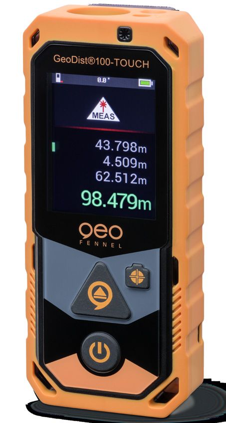
GeoDist® 100
BEDIENUNGSANLEITUNG
USER MANUAL
MODE D‘EMPLOI
www.geo-fennel.de
www.geo-fennel.com
www.geo-fennel.fr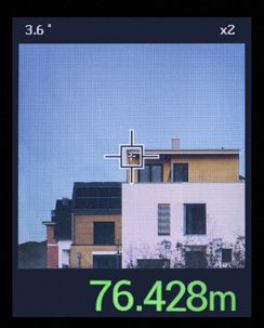
DE

Sehr geehrter Kunde,

vielen Dank für das Vertrauen, welches Sie uns beim Erwerb Ihres neuen
geo-FENNEL-Gerätes entgegengebracht haben. Dieses hochwertige Quali-
tätsprodukt wurde mit größter Sorgfalt produziert und qualitätsgeprüft.

Die beigefügte Anleitung wird Ihnen helfen, das Gerät sachgemäß zu
bedienen. Bitte lesen Sie insbesondere auch die Sicherheitshinweise vor
der Inbetriebnahme aufmerksam durch. Nur ein sachgerechter Gebrauch
gewährleistet einen langen und zuverlässigen Betrieb.

geo-FENNEL
Precision by tradition.

    Inhalt
    1. Lieferumfang                                                  A
    2. Stromversorgung                                               B
    3. Bedienelemente                                                C
    4. Bedienung                                                     D
    5. Sicherheitshinweise                                           E

2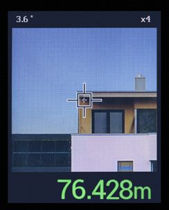
DE

     LIEFERUMFANG                                                         A
··   Laserentfernungsmesser GeoDist 100    ®

··   NiMH-Akkus
··   USB-Ladekabel
··   Holster
··   Handschlaufe
··   Bedienungsanleitung

 Technische Daten
 Messbereich                                       0,2 - 100 m*
 Genauigkeit Distanzmessung                        ±2 mm **
 Genauigkeit Neigungsmessung                       ± 0,3°
 Laserklasse                                       2 / rot
 Stromversorgung                                   NiMH
 Temperaturbereich                                 -10°C - +40°C
 Messeinheiten                                     m / ft / in / ft+in
 Staub-/Wasserschutz                               IP 65
 Abmessungen                                       115 x 50 x 26 mm
 Gewicht (mit Batterien)                           148 g
*Reduzierte Reichweite bei ungünstigen Messbedingungen
**Typische Genauigkeit, erhöht bei ungünstigen Messbedingungen

                                                                          3
DE
FUNKTIONEN
S. 8 ·· Horizontierungshilfen im Display
S. 9 ·· Kamerafunktion
S. 10 ·· Messebene
·· Addition / Subtraktion
·· Einzelmessung
·· Dauermessung
S. 11 ·· Flächenberechnung
·· Volumenberechnung
S. 12 ·· Pythagorasfunktion (Gesamthöhe) 2 Punkte
·· Pythagorasfunktion (Gesamthöhe) 3 Punkte
S. 13 ·· Pythagorasfunktion (Teilhöhe) 3 Punkte
S. 14 ·· Indirekte Messung 1
·· Indirekte Messung 2
S. 15 ·· Punkt-zu-Punkt-Messung
·· Trapezmessung 1
S. 16 ·· Trapezmessung 2
·· Flächenberechnung Dreieck
·· Flächenberechnung Kreis
S. 17 ·· Zylinderberechnung
·· Absteckfunktion
S. 18 ·· Offset-Funktion
·· Zeitverzögertes Messen
·· Speicherfunktion
S. 19 ·· Datenexport via USB
·· GeoDist®Connect App (Android + iOS)
S. 20 ·· Fehlerbehebung
4DE
STROMVERSORGUNG B
3 X AAA NIMH-AKKUS EINLEGEN
Achten Sie beim Einlegen der Akkus auf korrekte Polarität!
AKKU LADEN
Abdeckung der USB-Buchse (unten am Gerät) öffnen und Akku über den
USB-Anschluss laden. Hierfür ein handelsübliches USB-Ladegerät z.B. vom
Smartphone verwenden. Nach dem Ladevorgang die USB-Buchse wieder
verschließen.
Alternativ kann das Gerät auch mit AAA-Alkalinebatterien betrieben werden.
BEDIENELEMENTE C
1. Messtaste (kurz: Einzelmessung /
lang: Dauermessung)
2. AN-/AUS-Taste
kurz drücken = zurück
lang drücken = AN / AUS
3. Laserausgangsanzeige
4. Touch Screen
5. Kamerafunktion
Aktivierung / Zoom in / out
6. Batteriefach
7. Stativanschluss
5DE
D BEDIENUNG
DISPLAYANZEIGE
Gerät mit einschalten
-> nebenstehende Displayanzeige (Startbildschirm)
erscheint
TOUCH SCREEN
Das Gerät ist mit einem Touch Screen ausgestattet.
Vom Startbildschirm ausgehend:
·· nach rechts wischen
= Auswahl der Messmodi (Abb. 1)
·· nach links wischen
= addieren / subtrahieren (Abb. 2)
·· nach unten wischen
= Menüauswahl (Abb. 3+4)
Die Menüpunkte werden durch Antippen. Abb. 1+2 Abb. 3+4
bedient.
6DE
MENÜ
1. Bluetooth®-Funktion grau = aus
A = Automatiktransfer
M = Manuelltransfer
2. Messeinheit m / ft / in / ft+in (, ,,)
3. Messebene vorn, Stativanschluss, hinten
4. Digitale Libelle grau = aus
5. Display drehen
-> verfügbar im
Messmodus
6. Speicher ansehen wischen = blättern
= löschen
7. Offset einstellen Pfeiltasten = Auswahl der Dezimalstelle
+ / - = gewünschten Wert einstellen
8. Zeitverzögerte Messung Messung startet nach 5 Sekunden
Menü verlassen
7DE
DISPLAYANZEIGEN IM MESSMODUS
Winkelanzeige
Mess-
ebene Batteriezustands-
anzeige
Bluetooth®
Anzeige
Neigungs- Messmodus
anzeige
Messmodus
Messwert
1. Messwert
2. Messwert
3. Messwert
Volumen
HORIZONTIERUNGSHILFE IM DISPLAY
Zur Erhöhung der Messgenauigkeit bei horizontalen Messungen bietet
das Gerät Horizontierungshilfen im Display:
Nummerische Neigungsanzeige:
Halten Sie das Gerät möglichst bei 0°.
Optische Hilfe:
Grüner Balken – bewegen Sie den Balken
exakt zwischen die Markierungen.
8DE
ALLGEMEINE HINWEISE
·· Nach 3 Minuten ohne Bedienung schaltet sich das Gerät automatisch
ab.
·· Das Gerät speichert automatisch die letzten 1.000 Messwerte.
·· Der eingebaute Neigungssensor ist immer aktiv.
·· In allen Messmodi (außer Einzelmessung und Dauermessung) zeigt
die rote Linie an, welche Größe als nächste gemessen wird. Das
grüne L steht für die zu ermittelnde Größe.
KAMERAFUNKTION
Kamera-
funktion drücken, um in jedem Messmodus die
Kamerafunktion zu aktivieren, wenn der Laser-
zielpunkt mit dem Auge nicht zu sehen ist,
insbesondere bei Messungen im Außenbereich
Zoom in/out
Mit die Messung auslösen
9DE
MESSEBENE
Drücken, um die gewünschte Messebene festzulegen.
VORN STATIV HINTEN
ADDITION / SUBTRAKTION
In den Modi Entfernungsmessung, Flächenberechung
und Volumenberechnung nach links wischen und
+ oder - wählen, um die gewünschte Funktion
auszuführen.
EINZELMESSUNG
Gerät einschalten - Messmodus: Einzelmessung
Zum Messen Messtaste drücken
DAUERMESSUNG
gedrückt halten.
Vom Ausgangspunkt aus Gerät über den Zielpunkt bewegen.
Zum Beenden wieder drücken.
Anzeige: Maximum, Minimum und der zuletzt
gemessene Wert.
10DE
Navigation in den nachfolgenden Menüpunkten
Gewünschten Menüpunkt durch Wischen auswählen und durch
Antippen bestätigen.
Menüpunkt erneut ausführen
Menüpunkt verlassen
FLÄCHENBERECHNUNG
auswählen und drücken
drücken für das 1. Maß
drücken für das 2. Maß
Anzeige Zeile 3: Fläche
drücken für eine erneute Flächenberechnung, AUS-Knopf
drücken, um die Funktion zu verlassen
VOLUMENBERECHNUNG
auswählen und drücken
drücken für das 1. Maß
drücken für das 2. Maß
drücken für das 3. Maß
Anzeige Zeile 4: Volumen
drücken für eine erneute Flächenberechnung, AUS-Knopf
drücken, um die Funktion zu verlassen
11DE
PYTHAGORAS-MESSUNGEN
WICHTIG - unbedingt beachten
·· Bei der Messung der Horizontaldistanz (2. Maß) muss die Messung
im 90°-Winkel zur Messfläche erfolgen. Hierzu Neigungsanzeige
verwenden (0°).
·· Alle Messungen müssen vertikal in einer Linie liegen (ohne seitliche
Abweichung).
·· Zur Erhöhung der Messgenauigkeit Stativ verwenden.
PYTHAGORAS (2-PUNKT)
auswählen und drücken
drücken für die Schrägdistanz
drücken für die Horizontaldistanz
Anzeige Zeile 3: Höhe
PYTHAGORAS (3-PUNKT)
auswählen und drücken
drücken für die Schrägdistanz oben
drücken für die Horizontaldistanz
drücken für die Schrägdistanz unten
Anzeige Zeile 4: Höhe
12DE
PYTHAGORAS (3-PUNKT / TEILHÖHE)
auswählen und drücken
drücken für die Schrägdistanz oben
drücken für die Schrägdistanz unten
drücken für die Horizontaldistanz
Anzeige Zeile 4: Teilhöhe
INDIREKTE MESSUNGEN ÜBER NEIGUNG IN HOHER
GENAUIGKEIT
Wo direkte Messungen auf das Ziel nicht möglich sind, z.B. bei Glas-
fassaden ohne Messreflektion oder wenn das Messobjekt verdeckt ist:
Teilstrecken messen, fehlende Distanzen werden vom Gerät errechnet.
Hierbei der allgemeine Hinweis:
·· Alle Messungen müssen vertikal in einer Linie liegen (ohne seitliche
Abweichung).
·· Zur Erhöhung der Messgenauigkeit Stativ verwenden.
13DE
INDIREKTE MESSUNG 1
auswählen und drücken
drücken
Anzeige Zeile 1: Winkel
Anzeige Zeile 2: Schrägdistanz oben
Anzeige Zeile 3: Höhe
Anzeige Zeile 4: Horizontaldistanz
INDIREKTE MESSUNG 2
auswählen und drücken
drücken für Schrägdistanz oben (oberster Punkt)
drücken für Schrägdistanz unten (unterster Punkt)
Anzeige Zeile 1: Winkel
Anzeige Zeile 2: Schrägdistanz oben
Anzeige Zeile 3: Schrägdistanz unten
Anzeige Zeile 4: Höhe
14DE
PUNKT-ZU-PUNKT-MESSUNG
auswählen und drücken
Gerät ruhig halten und Selbstkalibrierung unbedingt abwarten
drücken für das 1. Maß
drücken für das 2. Maß
Anzeige Zeile 1: Winkel
Anzeige Zeile 2: Entfernung zum 1. Messpunkt
Anzeige Zeile 3: Entfernung zum 2. Messpunkt
Anzeige Zeile 4: Entfernung zwischen beiden Messpunkten
Zur Erhöhung der Genauigkeit, besonders auf längere Distanz,
Stativ verwenden!
TRAPEZMESSUNG 1
auswählen und drücken
drücken für das 1. Maß
drücken für das 2. Maß
drücken für das 3. Maß
Anzeige Zeile 4: Länge der Schräge, z.B. Dachschräge
15DE
TRAPEZMESSUNG 2
auswählen und drücken
drücken für das 1. Maß
drücken für das 2. Maß
Anzeige Zeile 1: Winkel Diagonale-Horizontale
Anzeige Zeile 2: Höhenmaß
Anzeige Zeile 3: Länge der Hypotenuse
Anzeige Zeile 4: Länge der Schräge, z.B. Dachschräge
FLÄCHENBERECHNUNG DREIECK
auswählen und drücken
drücken für das 1. Maß
drücken für das 2. Maß
drücken für das 3. Maß
Anzeige Zeile 4: Fläche des Dreiecks
FLÄCHENBERECHNUNG KREIS
auswählen und drücken
drücken für den Durchmesser
Anzeige Zeile 1: Durchmesser
Anzeige Zeile 2: Umfang
Anzeige Zeile 3: Fläche des Kreises
16DE
ZYLINDERBERECHNUNG
auswählen und drücken
drücken für den Durchmesser
drücken für die Höhe
Anzeige Zeile 1: Durchmesser
Anzeige Zeile 2: Höhe
Anzeige Zeile 3: Fläche des Zylinders
Anzeige Zeile 4: Volumen des Zylinders
ABSTECKFUNKTION
auswählen und drücken
·· mit den Pfeiltasten die Dezimalstelle ansteuern
·· mit + / - den gewünschten Wert einstellen
·· = Absteckung starten
Der rote Pfeil zeigt an, in welche Richtung das Gerät bewegt werden
muss, um die gewünschte Distanz zu erreichen. Bei Annäherung an
den Zielwert ertönt ein akustisches Signal.
17DE
OFFSET-FUNKTION
auswählen und drücken
·· mit den Pfeiltasten die Dezimalstelle ansteuern
·· mit + / - den gewünschten Offset einstellen
·· bestätigen mit
Die Aktivierung der Offset-Funktion wird im Display dauerhaft durch das
Symbol angezeigt.
ACHTUNG: Die Offset-Funktion ist dauerhaft aktiv, auch nach Aus-/
Einschalten des Gerätes. Funktion nach Beendigung immer deak-
tivieren.
ZEITVERZÖGERTES MESSEN
auswählen und drücken
Die Messung startet nach 5 Sekunden.
SPEICHERFUNKTION
Das Gerät speichert automatisch die letzten1.000 Messwerte.
Speicherabruf
18DE
DATENEXPORT VIA USB
GeoDist® 100 mit USB-Kabel an PC/Laptop anschließen.
Gerät im Explorer suchen und anklicken.
In der angezeigten Excel-Datei sind alle im Gerät gespeicherten Messwerte
aufgeführt.
GeoDist®Connect App (iOS und Android)
Kostenlose GeoDist®CONNECT APP für Android und iOS zur digitalen Wei-
terverarbeitung der Messungen:
·· Messsituationen fotografieren und bemaßen
·· importierte Fotos bemaßen
·· Skizzen erstellen und bemaßen
·· Messdatenlisten erstellen
Datenexport z.B. per e-mail zur weiteren Bearbeitung.
Sie finden die GeoDist®CONNECT APP für Smartphones / Tablets
iOS-Geräte ab iOS 7.0 im App Store
Android-Geräte ab Android 4.3 in Google Play
Kompatibel mit Bluetooth® 4.0 oder höher.
Die Bedienungsanleitung zur App finden Sie auf unserer Webseite
www.geo-fennel.de in der Rubrik Laser-Entfernungsmesser.
19DE
FEHLERBEHEBUNG
Code Ursache Maßnahme
204 Rechenfehler Messung gem. Bedienungsan-
leitung wiederholen
208 Überspannung Bitte kontaktieren Sie Ihren
Händler.
220 Akku zu schwach Akku laden
255 Signal zu schwach oder Messung auf eine andere Ober-
Messzeit zu lang fläche durchführen
256 Signal zu stark Messung auf eine andere Ober-
fläche durchführen
261 außerhalb des Messbe- Messung innerhalb des
reichs angegebenen Messbereichs
durchführen
500 Hardwarefehler Gerät mehrfach ein- und
ausschalten. Wenn der Fehler
weiterhin auftritt, kontaktieren
Sie bitte Ihren Händler
20DE
SICHERHEITSHINWEISE E
BESTIMMUNGSGEMÄSSE VERWENDUNG
Das Gerät sendet einen sichtbaren Laserstrahl aus, um z.B. folgende Mess-
aufgaben durchzuführen: Ermittlung von Distanzen.
UMGANG UND PFLEGE
Messinstrumente generell sorgsam behandeln. Nach Benutzung mit wei-
chem Tuch reinigen (ggfs. Tuch in etwas Wasser tränken). Wenn das Gerät
feucht war, sorgsam trocknen. Erst in den Koffer oder die Tasche packen,
wenn es absolut trocken ist. Transport nur in Originalbehälter oder -tasche.
UMSTÄNDE, DIE DAS MESSERGEBNIS VERFÄLSCHEN KÖNNEN
Messungen durch Glas- oder Plastikscheiben; verschmutzte Laseraustritts-
fenster; Sturz oder starker Stoß. Bitte Genauigkeit überprüfen.
Große Temperaturveränderungen: Wenn das Gerät aus warmer Umgebung
in eine kalte oder umgekehrt gebracht wird, vor Benutzung einige Minuten
warten.
ELEKTROMAGNETISCHE VERTRÄGLICHKEIT
Es kann nicht generell ausgeschlossen werden, dass das Gerät andere
Geräte stört (z.B. Navigationseinrichtungen); durch andere Geräte gestört
wird (z.B. elektromagnetische Strahlung bei erhöhter Feldstärke z.B. in der
unmittelbaren Nähe von Industrieanlagen oder Rundfunksendern).
CE-KONFORMITÄT
Das Gerät hat das CE-Zeichen gemäß den Normen EN 61326-1:2013,
61326-2-2:2013, 300 328 v2.1.1:2016, 62479:2010, 61010-1:2010.
21DE
GARANTIE
Die Garantiezeit beträgt zwei (2) Jahre, beginnend mit dem Verkaufsdatum.
Die Garantie erstreckt sich nur auf Mängel wie Material-oder Herstellungs-
fehler, sowie die Nichterfüllung zugesicherter Eigenschaften. Ein Garantiean-
spruch besteht nur bei bestimmungsgemäßer Verwendung. Mechanischer
Verschleiß und äußerliche Zerstörung durch Gewaltanwendung und Sturz
unterliegen nicht der Garantie. Der Garantieanspruch erlischt, wenn das
Gehäuse geöffnet wurde. Der Hersteller behält sich vor, im Garantiefall die
schadhaften Teile instand zusetzen bzw. das Gerät gegen ein gleiches oder
ähnliches (mit gleichen technischen Daten) auszutauschen. Ebenso gilt das
Auslaufen der Batterie nicht als Garantiefall.
WARN- UND SICHERHEITSHINWEISE
·· Richten Sie sich nach den Anweisungen der Bedienungsanleitung.
·· Anleitung vor Benutzung des Gerätes lesen.
·· Blicken Sie niemals in den Laserstrahl, auch nicht mit optischen Instru-
menten. Es besteht die Gefahr
·· von Augenschäden.
·· Laserstrahl nicht auf Personen richten.
·· Die Laserebene soll sich über der Augenhöhe von Personen befinden.
·· Niemals das Gehäuse öffnen. Reparaturen nur vom autorisierten Fach-
händler durchführen lassen.
·· Keine Warn- oder Sicherheitshinweise entfernen.
·· Lasergerät nicht in Kinderhände gelangen lassen.
·· Gerät nicht in explosionsgefährdeter Umgebung betreiben.
LASERKLASSIFIZIERUNG
Das Gerät entspricht der Lasersicherheitsklasse 2 gemäss der Norm DIN
EN 60825-1:2014. Das Gerät darf ohne weitere Sicherheitsmassnahmen
eingesetzt werden. Das Auge ist bei zufälligem, kurzzeitigem Hineinsehen
in den Laserstrahl durch den Lidschlussreflex geschützt.
Laserwarnschilder der Klasse 2 sind gut sichtbar
www.geo-fennel.de
GERMANY
Laser
am Gerät angebracht.
2
IEC 60825-1:2014
P ≤ 1 mW @ 635 - 670 nm
22DE
HAFTUNGSAUSSCHLUSS
1. Der Benutzer dieses Produktes ist angehalten, sich exakt an die
Anweisungen der Bedienungsanleitung zu halten. Alle Geräte sind vor
der Auslieferung genauestens überprüft worden. Der Anwender sollte
sich trotzdem vor jeder Anwendung von der Genauigkeit des Gerätes
überzeugen.
2. Der Hersteller und sein Vertreter haften nicht für fehlerhafte oder
absichtlich falsche Verwendung sowie daraus eventuell resultierende
Folgeschäden und entgangenen Gewinn.
3. Der Hersteller und sein Vertreter haften nicht für Folgeschäden und
entgangenen Gewinn durch Naturkatastrophen wie z.B. Erdbeben,
Sturm, Flut, usw. sowie Feuer, Unfall, Eingriffe durch Dritte oder einer
Verwendung außerhalb der üblichen Einsatzbereiche.
4. Der Hersteller und sein Vertreter haften nicht für Schäden und entgan-
genen Gewinn durch geänderte oder verlorene Daten, Unterbrechung
des Geschäftsbetriebes usw., die durch das Produkt oder die nicht
mögliche Verwendung des Produktes verursacht wurden.
5. Der Hersteller und sein Vertreter haften nicht für Schäden und ent-
gangenen Gewinn resultierend aus einer nicht anleitungsgemäßen
Bedienung.
6. Der Hersteller und sein Vertreter haften nicht für Schäden, die durch
unsachgemäße Verwendung oder in Verbindung mit Produkten anderer
Hersteller verursacht wurden.
23EN EN Dear Customer, Thank you for your confidence in us, having purchased a geo-Fennel instrument. For the optimum performance of the instrument, please read this ma- nual carefully and keep it in a convenient place for future reference. This manual contains important safety information that should be read and understood before use. Technical specification and design are subject to chance without notifi- cation. geo-FENNEL Precision by tradition. Inhalt 1. Supplied with A 2. Power supply B 3. Features C 4. Operation D 5. Safety notes E 24
EN
                                                                              EN

     SUPPLIED WITH                                                             A
··   Laser distance meter GeoDist 100      ®

··   NiMH rechargeable batteries
··   USB charging cable
··   Holster
··   Hand strip
··   User manual

 Technical data
 Measuring range                                        0,2 - 100 m*
 Measuring accuracy                                     ±2 mm **
 Tilt measurement accuracy                              ± 0,3°
 Laser class                                            2 / red
 Power supply                                           NiMH
 Temperature range                                      -10°C - +40°C
 Measuring units                                        m / ft / in / ft+in
 Dust / water protection                                IP 65
 Dimensions                                             115 x 50 x 26 mm
 Weight (with batteries)                                148 g
*May be shorter under unfavourable conditions
**Typical accuracy, may increase under unfavourable conditions

                                                                               25
EN
FEATURES
P. 30 ·· Levelling support in the display
P. 31 ·· Camera function
P. 32 ·· Measuring reference
·· Addition / subtraction
·· Single measurement
·· Contiuous measurement
P. 33 ·· Area calculation
·· Volume calculation
P. 34 ·· Pythagoras (2 point)
·· Pythagoras (3 point)
P. 35 ·· Pythagoras (3 point - partial height)
P. 36 ·· Indirect measurement 1
·· Indirect measurement 2
P. 37 ·· Measurement point-to-point
·· Trapezoid measurement 1
P. 38 ·· Trapezoid measurement 2
·· Triangle area calculation
·· Circle area calculation
P. 39 ·· Cylindrical volume
·· Stake out function
P. 40 ·· Offset function
·· Time-delayed measurement
·· Memory
P. 41 ·· Data export via USB
·· GeoDist®Connect App (iOS and Android)
P. 42 ·· Trouble shooting
26EN
POWER SUPPLY B
INSERT 3 X AAA NIMH BATTERIES
Ensure correct polarity when inserting the batteries.
CHARGE THE BATTERIES
Open the cover of the USB plug (bottom of the instrument) and charge
the batteries via the USB connection. For this use a standard USB charger,
i. e. from a smart phone. When the charging process is completed close
the USB plug.
Alternatively the instrument can be operated with standard AAA Alkaline
batteries.
FEATURES C
1. Measuring key (press briefly: single measurement /
press long: continuous measurement)
2. ON / OFF key
press briefly = back
press long = ON / OFF
3. Laser warning symbol
4. Touch screen
5. Camera function
activation / zoom in and out
6. Battery case
7. Tripod thread
27EN
D OPERATION
DISPLAY INDICATION
Power on the unit with
-> the left display indication (start screen)
will appear
TOUCH SCREEN
The instrument is equipped with a touch screen.
Coming from the start screen:
·· slide right
= selection of the measuring modes (pict. 1)
·· slide left
= add / subtract (pict. 2)
·· slide down
= menu (pict. 3+4)
The menu keys are operated with a finger tip. Abb. 1+2 Abb. 3+4
28EN
MENU
1. Bluetooth® function grey = off
A = automatic transfer
M = manual transfer
2. Measuring unit = m / ft / in / ft+in (, ,,)
3. Measuring reference front, tripod, rear
4. Digital vial grey = off
5. Rotate the display
-> available in
measuring mode
6. View memory slide = scroll
= delete
7. Define off-set arrow buttons = select digit
+ / - = set value
8. Time-delayed = measurement starts after 5 seconds
measurement
Quit the menu
29EN
DISPLAY INDICATION IN MEASURING MODE
Angle display
Measuring Battery status
reference indication
Bluetooth®
Measuring
Digital mode
level indication
display
Value
measured
Measuring
mode
1. Value measured
2. Value measured
3. Value measured
Volume
HORIZONTAL LEVELLING - DISPLAY INDICATION
In order to increase the measuring accuracy in horizontal direction the
instrument offers a levelling support in the display:
Numerical slope indication:
Preferably keep the instrument at 0°.
Optical support:
Green bar - move the bar exactly between
the marks.
30EN
GENERAL NOTES
·· After 3 minutes without operation the instruments powers off auto-
matically.
·· The instrument automatically saves the last 1.000 measured values.
·· The integrated tilt sensor 360° is always active.
·· In all measuring modes (except single and continuous measurement)
the red line shows which parameter will be measured next. The
green
L shows the parameter to be determined.
CAMERA FUNCTION
camera Press to activate the camera function in
function
all measuring modes, in case the target is not
visible with the eye - especially in case of
outdoor measurements.
= zoom in/out
Start the measurement with .
31EN MEASURING REFERENCE Press to select the requested measuring reference. FRONT TRIPOD REAR ADDITION / SUBTRACTION In the modes distance measurement, area and volume calculation slide left and select + or - to execute the requested task. SINGLE MEASUREMENT Power on the unit - measuring mode: single measurement For taking measurements press CONTINUOUS MEASUREMENT Keep pressed. Sweep slowly the unit back and forth over the selected target point. Press to stop the continuous measurement. Display indication: maximum, minimum and the last measured value. 32
EN

 Navigation within the following measuring modes

 Select the required menu item and confirm by a short press.

     = repeat the mode

     = leave the mode

AREA CALCULATION

Select and press

Press     for the first distance
Press     for the second distance
          Display indication line 3: area
Press     for a new area calculation, press the OFF button to
          quit this mode.

VOLUME CALCULATION

Select and press

Press     for the first distance
Press     for the second distance
Press     for the third distance
          Display indication line 4: volume
Press     for a new volume calculation, press the OFF button to
          quit this mode.

                                                                  33
EN
PYTHAGORAS MEASUREMENTS
IMPORTANT - it is essential to observe the following
·· When measuring the horizontal distance (2nd dimension), the
measurement must be taken at a 90° angle to the measuring sur-
face. To do this, use the inclination indicator (0°).
·· All measurements must be vertically in line (without lateral deviation).
·· Use a tripod to increase the measuring accuracy.
PYTHAGORAS (2-POINT)
Select and press
Press for the inclined distance
Press for the horizontal distance
Display indication line 3: height
PYTHAGORAS (3-POINT)
Select and press
Press for the inclined distance top
Press for the horizontal distance
Press for the inclined distance bottom
Display indication line 4: height
34EN
PYTHAGORAS (3-POINT / PARTIAL HEIGHT)
Select and press
Press for the inclined distance top
Press for the inclined distance bottom
Press for the horizontal distance
Display indication line 4: partial height
INDIRECT MEASUREMENTS VIA INCLINATION WITH HIGH
ACCURACY
Where direct measurements to the target are not possible, e.g. on glass
facades without measurement reflection or when the measurement
object is obscured:
Measure partial distances, missing distances are calculated by the
device.
Here a general note:
·· All measurements must be vertically in line (without lateral deviation).
·· Use a tripod to increase the accuracy of the measurement.
35EN
INDIRECT MEASUREMENT 1
Select and press
Press
Display indication line 1: angle
Display indication line 2: inclined distance top
Display indication line 3: height
Display indication line 4: horizontal distance
INDIRECT MEASUREMENT 2
Select and press
Press for the inclined distance top (top point)
Press for the inclined distance botton (bottom point)
Display indication line 1: angle
Display indication line 2: inclined distance top
Display indication line 3: inclined distance bottom
Display indication line 4: height
36EN
MEASUREMENT POINT-TO-POINT
Select and press
Hold the unit steady and imperatively wait until the self-calibration
is completed
Press for the first distance
Press for the second distance
Display indication line 1: angle
Display indication line 2: distance to the first measuring point
Display indication line 3: distance to the second measuring point
Display indication line 4: distance between both measuring
points
In order to increase the measuring accuracy - especially for long
distances - use a tripod!
TRAPEZOID MEASUREMENT 1
Select and press
Press for the first distance
Press for the second distance
Press for the third distance
Display indication line 4: length of the slope, i.e. slope of the roof
37EN
TRAPEZOID MEASUREMENT 2
Select and press
Press for the first distance
Press for the second distance
Display indication line 1: angle diagonal-horizontal
Display indication line 2: altitude
Display indication line 3: length of the hypotenuse
Display indication line 4: length of the slope, i.e. slope of the roof
TRIANGLE AREA CALCULATION
Select and press
Press for the first distance
Press for the second distance
Press for the third distance
Display indication line 4: triangle area
CIRCLE AREA CALCULATION
Select and press
Press for the diametre
Display indication line 1: diametre
Display indication line 2: circumference
Display indication line 3: circle area
38EN
CYLINDRICAL VOLUME
Select and press
Press for the diametre
Press for the height
Display indication line 1: diametre
Display indication line 2: height
Display indication line 3: cylinder area
Display indication line 4: cylinder volume
STAKE OUT FUNCTION
Select and press
·· switch the digits with the arrow buttons
·· define the requested offset with + / -
·· start with
The red arrow shows in which direction the unit must be moved to reach
the distance required. When approaching the target an accoustic signal
will sound.
39EN OFFSET FUNCTION Select and press ·· switch the digits with the arrow buttons ·· define the requested offset with + / - ·· confirm with The activation of the offset function will be displayed permanently by this symbol . ATTENTION: The offset function is permanently active, even after powering off/on of the unit. This function must be de-activated after finishing the measuring task. TIME-DELAYED MEASUREMENT Select and press The measurement starts after 5 seconds. MEMORY The instrument automatically saves the last 1.000 measured values. Data recall 40
EN

DATA EXPORT VIA USB

Conncect the GeoDist® 100 to a PC / laptop by means of the USB cable.

Search for the device within the explorer and click.

The excel file shown lists all measured values recorded.

GeoDist®Connect App (iOS and Android)

Free GeoDist®CONNECT APP for Android and iOS for digital processing of
the measurements:

··   photograph and dimension measurement situations
··   dimension imported photos
··   create and dimension sketches
··   create measurement data lists

Data export e.g. by e-mail for further processing.

You will find the GeoDist®CONNECT APP for smartphones / tablets

iOS units       from iOS 7.0     in the App Store
Android units   from Android 4.3 in Google Play

Compatible with Bluetooth® 4.0 or higher.

You will find the user manual for the App on our homepage
www.geo-fennel.de; category: laser distance meters.

                                                                         41
EN
TROUBLE SHOOTING
Code Cause Corrective action
204 Calculation error Repeat the measurement
208 Excessive current Contact your dealer
220 Battery weak Charge the battery
255 Signal too weak or Change the target surface
measuring time too long
256 Signal too strong Change the target surface
261 Out of measuring range Select the measuring distance
within the range
500 Hardware error Power on/off the device several
times. If the error code still
appears contact your dealer.
42EN
SAFETY NOTES E
INTENDED USE OF INSTRUMENT
The instrument emits a visible laser beam in order to carry out the following
measuring tasks (depending on the instrument): distance measurements.
SPECIFIC REASONS FOR ERRONEOUS MEASURING RESULTS
Measurements through glass or plastic windows; dirty laser emitting
windows; after the instrument has been dropped or hit. Please check the
accuracy.
Large fluctuation of temperature: If the instrument will be used in cold
areas after it has been stored in warm areas (or the other way round) please
wait some minutes before carrying out measurements.
CARE AND CLEANING
Handle measuring instruments with care. Clean with soft cloth only after
any use. If necessary damp the cloth with some water. If the instrument is
wet clean and dry it carefully. Pack it up only if it is perfectly dry. Transport in
original container / case only.
ELECTROMAGNETIC ACCEPTABILITY (EMC)
It cannot be completely excluded that this instrument will disturb other in-
struments (e.g. navigation systems); will be disturbed by other instruments
(e.g. intensive electromagnetic radiation nearby industrial facilities or radio
transmitters).
CE-Conformity
The instrument has the CE mark according to EN 61326-1:2013, 61326-2-
2:2013, 300 328 v2.1.1:2016, 62479:2010, 61010-1:2010.
43EN
EXCEPTIONS FROM RESPONSIBILITY
1. The user of this product is expected to follow the instructions given
in the user manual. Although all instruments left our warehouse in
perfect condition and adjustment the user is expected to carry out
periodic checks of the product’s accuracy and general performance.
2. The manufacturer, or its representatives, assumes no responsibility of
results of a faulty or intentional usage or misuse including any direct,
indirect, consequential damage, and loss of profits.
3. The manufacturer, or its representatives, assumes no responsibility for
consequential damage, and loss of profits by any disaster (earthquake,
storm, flood etc.), fire, accident, or an act of a third party and/or a
usage in other than usual conditions.
4. The manufacturer, or its representatives, assumes no responsibility for
any damage, and loss of profits due to a change of data, loss of data
and interruption of business etc., caused by using the product or an
unusable product.
5. The manufacturer, or its representatives, assumes no responsibility for
any damage, and loss of profits caused by usage other than explained
in the user manual.
6. The manufacturer, or its representatives, assumes no responsibility for
damage caused by wrong movement or action due to connecting with
other products.
WARRANTY
This product is warranted by the manufacturer to the original purchaser to
be free from defects in material and workmanship under normal use for
a period of two (2) years from the date of purchase. During the warranty
period, and upon proof of purchase, the product will be repaired or replaced
(with the same or similar model at manufacturers option), without charge
for either parts or labour. In case of a defect please contact the dealer
where you originally purchased this product. The warranty will not apply to
this product if it has been misused, abused or altered. Without limiting the
foregoing, leakage of the battery, bending or dropping the unit are presu-
med to be defects resulting from misuse or abuse.
44EN
SAFETY INSTRUCTIONS
·· Follow up the instructions given in the user manual.
·· Do not stare into the beam. The laser beam can lead to eye injury. A di-
rect look into the beam (even from greater distance) can cause damage
to your eyes.
·· Do not aim the laser beam at persons or animals.
·· The laser plane should be set up above the eye level of persons.
·· Use the instrument for measuring jobs only.
·· Do not open the instrument housing. Repairs should be carried out by
authorized workshops only. Please contact your local dealer.
·· Do not remove warning labels or safety instructions.
·· Keep the instrument away from children.
·· Do not use the instrument in explosive environment.
·· The user manual must always be kept with the instrument.
LASER CLASSIFICATION
The instrument is a laser class 2 laser product according to DIN IEC
60825-1:2014. It is allowed to use the unit without further safety precau-
tions. The eye protection is normally secured by aversion responses and the
blink reflex. The laser instrument is marked with class 2 warning labels.
www.geo-fennel.de
GERMANY
Laser
2
IEC 60825-1:2014
P ≤ 1 mW @ 515 - 530 nm
Please note:
If you return instruments for repair / for adjustment to us please
disconnect batteries or rechargeable batteries from the instrument -
this is for safety reasons!
Thank you.
45FR Cher client, Nous tenons à vous remercier pour la confiance que vous avez témoignée, par l‘acquisition de votre nouvel instrument geo-FENNEL. Les instructions de service vous aideront à vous servir de votre instrument de manière adéquate. Nous vous recommandons de lire avec soin tout particulièrement les consignes de sécurité de ladite notice avant la mise en service de votre appareil. Un emploi approprié est l‘unique moyen de garantir un fonctionnement efficace et de longue durée. geo-FENNEL Precision by tradition. Contenu 1. Livré comme suit A 2. Alimentation en courant B 3. Description de l‘apprareil C 4. Opération D 5. Consignes de sécurité E 46
FR

     LIVRÉ COMME SUIT                                                      A
··   Télémètre laser GeoDist 100 ®

··   Accus NiMH
··   Câble de charge USB
··   Étui
··   Dragonne
··   Mode d‘emploi

 Données techniques
 Portée                                             0,2 - 100 m*
 Précision mesure de distance                       ±2 mm **
 Précision mesure d‘inclinaison                     ± 0,3°
 Classe du laser                                    2 / rouge
 Alimentation en courant                            NiMH
 Plage de température                               -10°C - +40°C
 Unités de mesure                                   m / ft / in / ft+in
 Étanchéité                                         IP 65
 Dimensions                                         115 x 50 x 26 mm
 Poids (avec piles)                                 148 g
*Peut etre moins dans des conditions défavorables
**Précision type, peut augmenter dans des conditions défavorables

                                                                           47
FR
FONCTIONS
P. 52 ·· Support de nivellement sur l‘écran
P. 53 ·· Fonction caméra
P. 54 ·· Visée de mesure
·· Addition / soustraction
·· Mesure simple
·· Mesure continue
P. 55 ·· Cacul de surface
·· Calcul de volume
P. 56 ·· Fonction Pythagore (2 points)
·· Fonction Pythagore (3 points)
P. 57 ·· Fonction Pythagore (3 points - hauteur partielle)
P. 58 ·· Mesure indirecte 1
·· Mesure indirecte 2
P. 59 ·· Mesure de point à point
·· Mesure trapeze 1
P. 60 ·· Mesure trapeze 2
·· Calcul du triangle
·· Calcul du cercle
P. 61 ·· Volume cylindre
·· Fonction implantation
P. 62 ·· Fonction décalage (Offset)
·· Mesure temporisée
·· Fonction mémoire
P. 63 ·· Transfert des données via USB
·· GeoDist®Connect App (Android + iOS)
P. 64 ·· Dépannage
48FR
ALIMENTATION EN COURANT B
MISE EN PLACE DES ACCUS (3 X AAA NIMH)
Attention à la polarité en mettant en place les accus!
CHARGER L‘ ACCU
Ouvrez le couvercle de la douille USB (sol de l‘appareil) et chargez l‘accu
via la connexion USB. Utilisez un chargeur standard USB p. e.
d‘un Smartphone. Après avoir chargé l‘accu fermez la douille USB.
Alternativement l‘appareil travaille avec des piles alcalines AAA.
DESCRIPTION DE L‘APPAREIL C
1. Bouton mesure (pressez bref: mesure simple /
pressez long: mesure continue)
2. Bouton MARCHE / ARRÊT
Pressez bref: retour
Pressez long: MARCHE / ARRÊT
3. Symbole d‘avertissement laser
4. Touch Screen
5. Caméra: activation / Zoom in / out
6. Couvercle du compartiment piles
7. Filetage trépied
49FR
D OPÉRATION
ÉCRAN
Mettez en marche l‘appareil avec
-> l‘affichage à gauche (écran de
départ) apparaît
TOUCH SCREEN
L‘ appareil est équippé d‘un Touch Screen.
A partir de l‘écran de départ:
·· glissez à droite
= sélection des modes de mesure (image 1)
·· glissez à gauche
= additionner / soustraire (image 2)
·· glissez en bas
= sélection du menu (image 3+4)
Touchez les points avec le doigt pour confirmer
le mode désiré.
Abb. 1+2 Abb. 3+4
50FR
MENU
1. Fonction Bluetooth® gris = éteint
A = transfert automatique
M = transfert manuel
2. Unité de mesure = m / ft / in / ft+in (, ,,)
3. Visée de mesure devant, trépied arrière
4. Niveau digital gris = éteint
5. Orienter l‘écran = marche / arrêt (gris = arrêt)
-> disponible en
mode mesure
6. Regarder la mémoire glisser = faire défiler
= effacer
7. Régler l‘off-set boutons flèche = sélection de la
décimale
+ / - = définir la valeur
8. Mesure temporisée = la mesure commence dans les
5 secondes
Quittez le menu
51FR
AFFICHAGE DE L‘ÉCRAN EN MODE MESURE
Visée de Affichage angle
mesure Affichage
état de pile
Bluetooth®
Affichage
Affichage mode de
inclinaison mesure
Valeur de
mesure
Mode de mesure
1. valeur de mesure
2. valeur de mesure
3. valeur de mesure
Volume
NIVELLEMENT HORIZONTAL - AFFICHAGE DE L‘ÉCRAN
Pour augmenter la précision de mesure pour des mesures horizontaux
l‘appareil offre des supports de nivellement dans l‘écran:
Affichage de l‘inclinaison numérique:
Tenez l‘appareil à 0° si possible.
Support optique:
Barre verte - bougez la barre exactement
entre les marques.
52FR
INFORMATIONS GÉNÉRALES
·· Après 3 minutes sans opération l‘appareil s‘eteint automatiquement.
·· L‘ appareil mémorise les 1.000 dernières valeurs de mesure automa-
tiquement.
·· Le capteur d‘inclincaison intégré est toujours actif.
·· Dans tous les modes de mesure (sauf la mesure simple et continue)
la ligne rouge affiche quelle valeur sera mesuré suivant. Le L vert
affiche la valeur à être mesurée.
FONCTION CAMÉRA
fonction
caméra Pressez pour activer la fonction caméra
dans chaque mode de mesure si la cible n‘est
pas visible avec les yeux, particulièrement pour
des mesures à l‘extérieur.
= Zoom in/out
Activez la mesure avec .
53FR VISÉE DE MESURE Pressez pour définir la visée de mesure désirée. DEVANT TRÉPIED ARRIÈRE ADDITION / SOUSTRACTION Dans les modes mesure de distance, calcul de surface et de volume glissez à gauche et sélectionnez + ou - pour exécuter la fonction désirée. MESURE SIMPLE Mettez l‘instrument en marche - mode de mesure: mesure simple. Pour mesurer pressez: MESURE CONTINUE Maintenez pressé . A partir du point de départ, déplacez l‘appareil sur le point cible. Pour termi- ner pressez . Affichage: maximum, minimum et la dernière valeur mesurée. 54
FR

 Navigation dans les modes de mesure suivants

      répéter le mode de mesure précédent

      quitter le mode de mesure

CALCUL DE SURFACE

Sélectionnez et pressez

Pressez     pour la 1ère distance
Pressez     pour la 2ième distance
            Affichage ligne 3: la surface
Pressez     pour exécuter un autre calcul de surface; pressez le touche
            MARCHE/ARRÊT pour quitter ce mode.

CALCUL DE VOLUME

Sélectionnez et pressez

Pressez     pour la 1ère distance
Pressez     pour la 2ième distance
Pressez     pour la 3ième distance
            Affichage ligne 4: le volume
Pressez     pour un nouveau calcul de volume; pressez le touche
            MARCHE/ARRÊT pour quitter ce mode.

                                                                           55
FR
LES MESURES DE PYTHAGORE
IMPORTANT - il est essentiel d‘observer les points suivants
·· Lors de la mesure de la distance horizontale (2e dimension), la me-
sure doit être effectuée à un angle de 90° par rapport à la surface de
mesure. Pour ce faire, utilisez l‘indicateur d‘inclinaison (0°).
·· Toutes les mesures doivent être alignées verticalement (sans dévia-
tion latérale).
·· Utilisez un trépied pour augmenter la précision des mesures.
PYTHAGORE (2 POINTS)
Sélectionnez et pressez
Pressez pour la distance inclinée
Pressez pour la distance horizontale
Affichage ligne 3: la hauteur
PYTHAGORE (3 POINTS)
Sélectionnez et pressez
Pressez pour la distance inclinée en haut
Pressez pour la distance horizontale
Pressez pour la distance inclinée en bas
Affichage ligne 4: la hauteur
56FR
PYTHAGORE (3 POINTS / HAUTEUR PARTIELLE)
Sélectionnez et pressez
Pressez pour la distance inclinée en haut
Pressez pour la distance inclinée en bas
Pressez pour la distance horizontale
Affichage ligne 4: la hauteur partielle
DES MESURES INDIRECTES VIA L‘INCLINAISON AVEC UNE
GRANDE PRÉCISION
Lorsque les mesures directes sur la cible ne sont pas possibles, par
exemple sur des façades en verre sans réflexion de la mesure ou si
l‘objet de la mesure est obscurci : Mesurez les distances partielles, les
distances manquantes sont calculées par l‘appareil.
Voici la note générale:
·· Toutes les mesures doivent être alignées verticalement (sans dévia-
tion latérale).
·· Utilisez un trépied pour augmenter la précision de la mesure.
57FR
MESURE INDIRECTE 1
Sélectionnez et pressez
Pressez
Affichage ligne 1: angle
Affichage ligne 2: distance inclinée en haut
Affichage ligne 3: hauteur
Affichage ligne 4: distance horizontale
MESURE INDIRECTE 2
Sélectionnez et pressez
Pressez pour la distance inclinée en haut (point le plus haut)
Pressez pour la distance inclinée en bas (point le plus bas)
Affichage ligne 1: angle
Affichage ligne 2: distance inclinée en haut
Affichage ligne 3: distance inclinée en bas
Affichage ligne 4: hauteur
58FR
MESURE DE POINT À POINT
Sélectionnez et pressez
Tenez l‘appareil tranquillement et attendez impérativement le calibrage.
Pressez pour la 1ière distance
Pressez pour la 2ième distance
Affichage ligne 1: angle
Affichage ligne 2: distance jusqu‘à la cible 1
Affichage ligne 3: distance jusqu‘à la cible 2
Affichage ligne 4: distance entre les deux cibles
Pour augmenter la précision, particulièrement sur de longues di-
stances, utilisez un trépied!
MESURE TRAPEZE 1
Sélectionnez et pressez
Pressez pour la 1ière distance
Pressez pour la 2ième distance
Pressez pour la 3ième distance
Affichage ligne 4: longueur du biais, p.e. du pan du toit
59FR
MESURE TRAPEZE 2
Sélectionnez et pressez
Pressez pour la 1ière distance
Pressez pour la 1ière distance
Affichage ligne 1: angle de la diagonale-horizontale
Affichage ligne 2: l‘élévation
Affichage ligne 3: longueur de l‘hypoténuse
Affichage ligne 4: longueur du biais, p.e. du pan du toit
CALCUL DU TRIANGLE
Sélectionnez et pressez
Pressez pour la 1ière distance
Pressez pour la 2ième distance
Pressez pour la 3ième distance
Affichage ligne 4: la surface du triangle
CALCUL DU CERCLE
Sélectionnez et pressez
Pressez pour le diamètre
Affichage ligne 1: diamètre
Affichage ligne 2: périmètre
Affichage ligne 3: surface du cercle
60FR
VOLUME CYLINDRE
Sélectionnez et pressez
Pressez pour le diamètre
Pressez pour la hauteur
Affichage ligne 1: diamètre
Affichage ligne 2: hauteur
Affichage ligne 3: surface du cylindre
Affichage ligne 4: volume du cylindre
FONCTION IMPLANTATION
Sélectionnez et pressez
·· sélectionnez la décimale avec les boutons flèche
·· définez la valeur désirée avec +/ -
·· démarrez l‘implantation avec
La flèche rouge affiche dans quelle direction l‘appareil doit être agité
pour atteindre la distance désirée. Rapprochant à la valeur cible un signal
sonore retentit.
61FR FONCTION DÉCALAGE (OFFSET) Sélectionnez et pressez ·· sélectionnez la décimale avec les boutons flèche ·· définez la valeur offset avec +/ - ·· confirmez avec L‘ activation de la fonction OFFSET est affichée sur l‘écran permanente- ment par le symbol . ATTENTION: La fonction OFFSET est active permanentement, même après éteindre / remettre en marche l‘appareil. Déactivez la fonction impérativement après l‘achèvement de votre travail. MESURE TEMPORISÉE Sélectionnez et pressez La mesure démarra après 5 secondes. FONCTION MÉMOIRE L‘ appareil enregistre automatiquement les 1.000 dernières valeurs mesurées. Rappel de la mémoire 62
FR

TRANSFERT DES DONNÉSS VIA USB

Connectez le GeoDist® 100 avec un ordinateur portable/individuel par un
câble USB.

Cherchez l‘appareil dans l‘explorateur et le cliquez.

Dans le fichier excel affiché vous trouvez tous les mesures mémorisées
dans votre appareil.

GeoDist®Connect App (iOS et Android)

GeoDist®CONNECT APP gratuite sur Android et iOS pour le traitement
numérique des mesures :

··   localisation des photographies et des cotes mesurées
··   import de photos et les coter
··   création et cotation de croquis
··   création de listes de données

Export par e-mail pour un traitement ultérieur.

Vous trouvez la GeoDist®CONNECT APP pour des smartphones / tablettes:

Appareil iOS       à partir de iOS 7.0        dans App Store
Apparel Android    à partir de Android 4.3    dans Google Play

Compatible avec Bluetooth® 4.0 ou mieux.

Vous trouvez le mode d‘emploi pour l‘App sur notre site:
www.geo-fennel.de dans la rubrique télémètres.

                                                                           63
FR
DÉPANNAGE
Code Raison Action
204 Erreur de calcul Répétez la mesure selon le
mode d‘emploi
208 Surtension Contactez votre distributeur
220 Accu trop faible Chargez l‘accu
255 Signal trop faible ou Mesurez sur une autre surface
temps de mesure trop
long
256 Signal trop fort Mesurez sur une autre surface
261 Mesure hors de la Effectuez la mesure dans la
portée portée
500 Erreur matérielle Mettez l‘appareil en marche/
arrêt plusieurs fois. Si l‘erreur
continue, contactez votre
distributeur.
64FR
CONSIGNES DE SÉCURITÉ E
UTILISATION CONFORME AUX PRÉSCRIPTIONS
Le niveau projette un faisceau laser visible, pour effectuer p. ex. les travaux
de mesures suivants: détermination de l‘hauteur, tracé d’angles droits,
pointage de plans de référence horizontaux ainsi qu’obtention de points
d’aplomb (dépendant de l‘instrument).
CIRCONSTANCES POUVANT FAUSSER LES RÉSULTATS DE MESURES
Mesures effectuées à travers des plaques de verre ou de matière plastique;
mesures effectuées à travers la fenêtre de sortie du faisceau laser
lorsqu‘elle est sale. Mesures après que le niveau soit tombé ou ait subi
un choc très fort. Mesures effectuées pendant de grandes différences de
température - p. ex. lorsque l‘instrument passe rapidement d‘un milieu très
chaud à un autre très froid; attendre alors quelques minutes d‘adaptation
avant de réutiliser le niveau.
NETTOYAGE ET REMISAGE
Essuyer l‘instrument mouillé, humide ou sali en le frottant uniquement
avec un tissu de nettoyage. Quant à l‘optique, la nettoyer avec un tissu fin
comme p. ex. un tissu feutré de lunettes.
Ne jamais mettre un instrument humide dans un coffret fermé! Le laisser
sécher auparavant au moins pendant un jour dans un local chauffé! Trans-
port seulement dans le coffret original.
COMPATIBILITÉ ÉLECTROMAGNÉTIQUE
De manière générale, il n‘est pas exclu que le niveau ne dérange d‘autres
instruments (p. ex. les dispositifs de navigation) ou qu‘il puisse lui-même
être dérangé par d‘autres appareils (p. ex. soit par un rayonnement électro-
magnétique dû à une élévation de l‘intensité du champ, soit par la proximité
d‘installations industrielles ou d‘émetteurs de radiodiffusion).
65FR
CONFORMITÉ CE
Le niveau porte le label CE conformément aux normes EN 61326-1:2013,
61326-2-2:2013, 300 328 v2.1.1:2016, 62479:2010, 61010-1:2010.
GARANTIE
La durée de garantie est de deux (2) ans à partir de la date d‘achat. Cette
garantie ne couvre que les défauts tels que le matériel défectueux ou les
anomalies de fabrication, ainsi que le manque des propriétés prévues. Le
droit à la garantie n‘est valable que si l‘utilisation du niveau a été conforme
aux préscriptions. En sont exclus l‘usure mécanique et un endommage-
ment externe par suite d‘usage de la force et/ou d‘une chute. Le droit à la
garantie prend fin lorsque le boîtier a été ouvert. Dans un cas couvert par
la garantie, le fabricant se réserve le droit de remettre en état les éléments
défectueux ou d‘échanger l‘instrument par un autre identique ou similaire
(possédant les mêmes caractéristiques techniques). De même, un endom-
magement résultant d‘un écoulement de l‘accumulateur n‘est pas couvert
par la garantie.
CLASSIFICATION DES LASERS
Ce niveau correspond à la classe de sécurité des lasers 2, conformément
à la norme DIN EN 60825-1:2014. De ce fait, l’instrument peut être utilisé
sans avoir recours à d’autres mesures de sécurité. Au cas où l’utilisateur
a regardé un court instant le faisceau laser, les yeux sont tout de même
protégés par le réflexe de fermeture des paupières.
Les pictogrammes de danger de la classe 2 sont bien
visibles sur l‘appareil.
www.geo-fennel.de
GERMA NY
Laser
2
IEC 60825-1:2014
P ≤ 1 mW @ 515 - 530 nm
Merci de respecter le suivant impérativement:
Si vous retournez des instruments pour réparation / ajustage vous
devez - pour des raisons de sécurité - impérativement enlever les
accus.
Merci.
66FR
EXCLUSION DE LA RESPONSABILITÉ
1. L‘utilisateur de ce produit est tenu de respecter ponctuellement les in-
structions du mode d‘emploi. Tous les instruments ont été très soigneu-
sement vérifiés avant leur livraison. Toutefois, l‘utilisateur devra s‘assurer
de la précision de ce niveau avant chaque emploi.
2. Le fabricant et son représentant déclinent toute responsabilité dans le
cas d‘utilisation incorrecte ou volontairement anormale ainsi que pour
les dommages consécutifs en découlant, tout comme pour les béné-
fices non réalisés.
3. Le fabricant et son représentant déclinent toute responsabilité pour
les dommages consécutifs et les bénéfices non réalisés par suite de
catastrophes naturelles, comme p. ex. tremblement de terre, tempête,
raz de marée etc. ainsi que d‘incendie, accident, intervention malinten-
tionnée d‘une tierce personne, ou encore dus à une utilisation hors du
domaine d‘application normal de l‘instrument.
4. Le fabricant et son représentant déclinent toute responsabilité pour les
dommages et les bénéfices non réalisés par suite de modification ou
perte de données, interruption du travail de l‘entreprise etc., à savoir les
dommages qui découlent du produit lui-même ou de la non-utilisation du
produit.
5. Le fabricant et son représentant déclinent toute responsabilité pour les
dommages et le bénéfices non réalisés par suite d‘une manoeuvre non
conforme aux instructions.
6. Le fabricant et son représentant déclinent toute responsabilité pour les
dommages et les bénéfices non réalisés qui decoulent d‘une utilisation
inadéquante ou en liaison avec des produits d‘autres fabricants.
67geo-FENNEL GmbH
Technische Änderungen vorbehalten.
Kupferstraße 6 All instruments subject to technical changes.
D-34225 Baunatal Sous réserve de modifications techniques.
Tel. +49 561 / 49 21 45
Fax +49 561 / 49 72 34
info@geo-fennel.de
www.geo-fennel.de 03/2021
Precision by tradition.Sie können auch lesen