SENEC.Wallbox pro s Betriebsanleitung Operating instructions Manuel d instructions Instruzioni per l uso
←
→
Transkription von Seiteninhalten
Wenn Ihr Browser die Seite nicht korrekt rendert, bitte, lesen Sie den Inhalt der Seite unten
SENEC.Wallbox pro s

Betriebsanleitung
Operating instructions
Manuel d´instructions
Instruzioni per l´uso

         Download:
         mein-senec.de > Downloads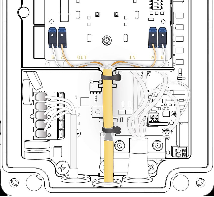
I                                          II

Deutsch    14
English    22
Français   30   Contact
                SENEC GmbH
Italiano   38
                Hotline: +49 341 870 57 0
                Fax: +49 341 870 57 300
                E-Mail: info@senec.com

                Language German & English
                Website: www.senec.com

                                                 2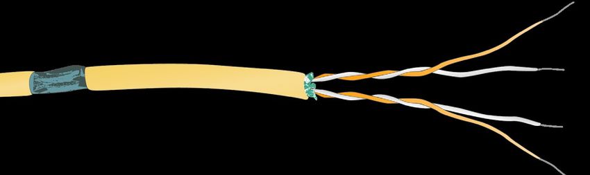
III

1 x Wallbox-Cover       1 x Wallbox
                    SENEC.Wallbox pro s          4 x M4x10 T20        2 x EADR25

                                               2 x ESKV25        1x MFD 25/03/073

    IV

          1.            2.                3.                4.             5.

                                  Chapter 1.2

3
V

     Ø max. 10mm
     Ø max. 10mm
     M = 12 Nm
                                           210mm

                                           105mm

                            260mm

                                    16kg           1000 – 1100mm

VI    SENEC.Wallbox pro s

                                                                   4
VII
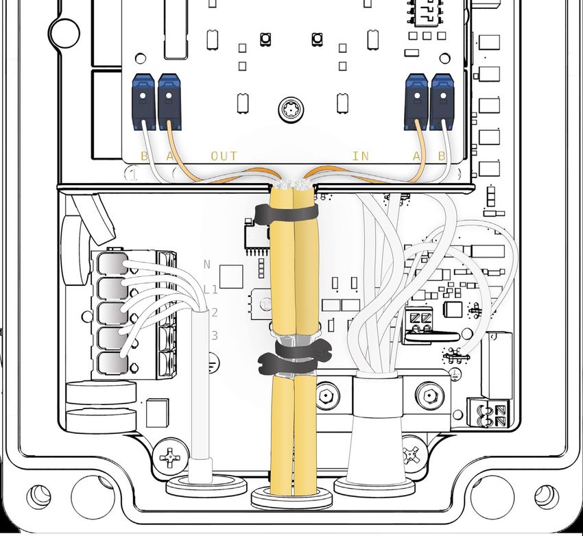
Eska ESKV25
M = 8Nm
Eska EADR25 M = 4Nm
Ø 9 – 17mm
max. 5 x 6mm²
130mm 11 – 13mm
1N~ 3N~
230V 50Hz 400V 50Hz
5VIII
6IX
Max Current:
0 = 6A
1 = 8A
2= 10A “S1”
3= 12A
4= 14 A
5….9 = 16A
Digital Output
1 NL / IT
RCD type A: IΔ = 30mA
MCB (LS): max. 16A
Chapter 1.2 & 1.5
7X
Ø 5,3 – 7,3mm
max. 2 x 0,5mm²
100mm 30mm 6mm
Chapter 1.8.3
8XI SENEC.Wallbox pro s
Chapter 2.2
9XII SENEC.Wallbox pro s
S2 S3 S4 S5
S6
S5/1
ON S5
OFF S5 t = 5min
Chapter 2.2.2
10XIII SENEC.Wallbox pro s
XIV SENEC.Wallbox pro s
ON
t = 5min
1
2
3
4
5
6
7
Chapter 2.2.2
11XV
Chapter 2.2.1
XVI SENEC.Wallbox pro s
1
4
Chapter 1.7
2
3
12XVI SENEC.Wallbox pro s
1
2
Chapter 1.8
13Deutsch
Deutsch
Inhaltsverzeichnis
1. SICHERHEITSHINWEISE 15
1.1 Hinweis an den Betreiber und an den Bediener des
Ladesystems15
1.2 Bestimmungsgemäße Verwendung 15
1.3 Hinweise für Personen mit Herzschrittmacher
(PM - Pacemaker) oder implantiertem Defibrillator
(ICD - Implantable Cardioverter Defibrillator) 16
1.4 Arbeiten am Ladesystem ohne Gefährdungen 17
1.5 Installation und Prüfungen 17
1.6 Hinweise zu verwendeten Zeichen, Symbolen und
Kennzeichnungen18
1.7 Schutzeinrichtungen 18
1.8 Typenschild, Frontbeleuchtung und
Sperreinrichtung 18
1.8.1 Typenschild 18
1.8.2 Frontbeleuchtung 18
1.8.3 Sperreinrichtung 19
1.8.4 Konfigurierbare Sperreinrichtung 19
1.9 Umwelt 19
1.10 Konformitätserklärung 19
2. BEDIENUNGSANLEITUNG 19
2.1 Reinigung der Wallbox 19
2.2 Bedienung 19
2.2.1 Laden eines Fahrzeugs 19
2.2.2 Diagnose 20
2.2.3 Lastmanagement (optional) 21
14Deutsch
Angabe technische Spezifikation
Normen EN 61851-1; EN 61439-7 (AEVSC)
Ladekapazität Mode 3 bis zu 11 kW
Nennspannung 230 V / 400 V / 1/3 AC
Nennstrom bis zu 16 A, anpassbar von 6 A bis 16 A in 2 A Schritten
Nennfrequenz 50 Hz
Verbindungsmethode Federklemmen
Ladeverbindung/Ladekupplung Typ 2
Länge Ladekabel 7,5 m
Betriebs-/Statusinformationen LED Anzeige
Schutzart IP54
Stoßfestigkeitsgrad IK08
Fehlerstromerkennung DC 6 mA (IEC62955)
Umgebungstemperatur -25 °C bis +40 °C -25
Aufstellung Wandmontage | Stelenmontage
Schutzklasse I
Überspannungskategorie III
Verschmutzungsgrad 3
Abmessungen (HxBxT) 410 mm x 295 mm x 114 mm
Gewicht ca. 8,5 kg
1. SICHERHEITSHINWEISE • Das Ladesystem ist nur für den Betrieb in TT-,
Beachten Sie die nachfolgenden Hinweise für einen TNC- und TNCS-Netzen vorgesehen. Das Lade-
sicheren Aufbau und Betrieb der Wallbox. system darf nicht in IT-Netzen betrieben werden.
• Das Ladesystem ist nicht zum Laden von Fahr-
1.1 Hinweis an den Betreiber und an zeugen mit gasenden Batterien (beispielsweise
den Bediener des Ladesystems
Bleiakkumulatoren) geeignet.
• Lesen Sie vor Inbetriebnahme des Ladesystems
• Das Ladesystem ist ausschließlich für die statio-
die Bedienungsanleitung.
näre Montage bestimmt. Das Ladesystem ist für
• Stellen Sie sicher, dass alle Personen, die an die Montage im Freien geeignet.
diesem Ladesystem arbeiten oder es benutzen
• Das Ladesystem darf nur von Personen bedient
die Bedienungsanleitung gelesen haben.
und verwendet werden, die die Bedienungs-
• Stellen Sie sicher, dass Sie die Vorschriften und anleitung gelesen haben.
Anweisungen für sicheres Arbeiten befolgen.
• Die elektrische Installation, Inbetriebnahme
• Bewahren Sie die Gerätedokumentation so auf, und Wartung des Ladesystems darf nur durch
dass sie den Bedienern des Ladesystems immer qualifizierte Elektrofachkräfte erfolgen, die vom
zur Verfügung steht. Betreiber dazu autorisiert wurden.
• Stellen Sie sicher, dass keine unbefugten • Die qualifizierten Elektrofachkräfte müssen die
Personen Zugang zum Ladesystem haben. Gerätedokumentation gelesen und verstanden
haben und deren Anweisungen befolgen.
1.2 Bestimmungsgemäße Verwendung
Das Ladesystem ist für den Einsatz im privaten und
Anforderungen an die Qualifikation von
halb-öffentlichen Bereich vorgesehen, z. B. Privat-
Elektrofachkräften
grundstücke, Firmenparkplätze oder Betriebshöfe.
Kenntnis und Beachtung der 5 Sicherheitsregeln für
Verwenden Sie das Ladesystem nicht an Orten, an
das Arbeiten an elektrischen Anlagen:
denen explosionsfähige oder brennbare Substanzen
1. Freischalten.
(z. B. Gase, Flüssigkeiten oder Stäube) lagern oder
2. Gegen Wiedereinschalten sichern.
vorhanden sind. Das Ladesystem dient ausschließ-
lich zum Laden von Elektrofahrzeugen. 3. Spannungsfreiheit feststellen.
• Ladung nach Mode 3 gemäß IEC 61851‑1 4. Erden und kurzschließen.
• Steckvorrichtungen gemäß IEC 62196
15Deutsch
5. Benachbarte, unter Spannung stehende Teile Besondere Betriebsbedingungen für die Schweiz
abdecken oder abschranken. Verwenden Sie bei der Version mit 7,5 m Ladekabel
Das Wiedereinschalten erfolgt in umgekehrter in der Schweiz ein Leitungsführungssystem.
Reihenfolge.
• Kenntnis der allgemeinen und speziellen Sicher- Besondere Betriebsbedingungen für die Nieder-
heitsvorschriften und Unfallverhütungsvorschriften. lande und Italien
Schließen Sie an den digitalen Ausgang SW
• Kenntnis der einschlägigen elektrotechnischen
(Abb. IX Nr. 1) beispielsweise eine Fernauslösung für
Vorschriften z. B. für die Prüfung bei Erstinbetrieb-
den vorgeschalteten RCD oder einen Schütz an.
nahme und die Anforderungen für Betriebsstätten,
Umax = 24 V
Räume und Anlagen besonderer Art - Stromver-
Imax = 3 A
sorgung von Elektrofahrzeugen.
• Fähigkeit, Risiken zu erkennen und mögliche
Der Hersteller kann nur für den Auslieferungs-
Gefährdungen zu vermeiden.
zustand des Ladesystems und für alle vom
Die nationalen Sicherheitsvorschriften und Unfall- Fachpersonal des Herstellers geleisteten Arbeiten
verhütungsvorschriften sind bei der Bereitstellung Verantwortung übernehmen.
des Ladesystems und beim Umgang mit dem Lade-
system vom Betreiber, vom Bediener und von der 1.3 Hinweise für Personen mit Herz-
Elektrofachkraft zu beachten. Die nicht bestimmungs- schrittmacher (PM - Pacemaker)
gemäße Verwendung sowie die Nichtbeachtung der oder implantiertem Defibrillator
Bedienungsanleitung kann gefährden: (ICD - Implantable Cardioverter
• Ihr Leben,
Defibrillator)
Ladesysteme dieses Herstellers, die bestimmungs-
• Ihre Gesundheit,
gemäß betrieben werden, erfüllen die europäische
• Ladesystem und Fahrzeug.
Richtlinie über die elektromagnetische Verträg-
lichkeit hinsichtlich der Störabstrahlung. Sollten
Sicherheitseinrichtungen am Ladesystem
Personen mit Herzschrittmacher oder Defibrillator
• Nicht abmontieren.
an Ladesystemen und deren Einrichtungen
• Nicht manipulieren. Tätigkeiten im bestimmungsgemäßen Normal-
• Nicht umgehen. betrieb ausführen wollen, kann der Hersteller
• Vor jeder Verwendung prüfen, dass die Ausrüstung des Ladesystems keine Aussage hinsichtlich der
(z. B. Gehäuse, Anschlussleitung, Ladekupplung) Eignung solcher medizinischer Geräte treffen.
unbeschädigt ist. Der Hersteller des Ladesystems ist nicht in der
• Wenn erforderlich, reparieren oder ersetzen lassen, Lage, die entsprechenden Herzschrittmacher oder
damit die Funktionseigenschaft gewahrt bleibt. Defibrillatoren hinsichtlich ihrer Anfälligkeit gegen
elektromagnetische Strahlungen zu beurteilen. Dies
Tragen Sie dafür Sorge, dass:
kann nur der Hersteller des Herzschrittmachers
• Sicherheitskennzeichnungen, z. B. gelbe farbliche
oder des Defibrillators tun. Der Hersteller des Lade-
Markierungen,
systems empfiehlt daher, betroffene Personen erst
• Warnschilder und
nach Rücksprache mit dem Hersteller des Herz-
• Sicherheitsleuchten dauerhaft gut erkennbar schrittmachers oder des Defibrillators sowie dem
bleiben und ihre Wirksamkeit behalten. zuständigen Versicherer an unseren Ladesystemen
• Verwenden Sie für den Betrieb des Ladesystems arbeiten zu lassen. Stellen Sie auf jeden Fall im
keine Verlängerungskabel, Kabeltrommeln, Mehr- Vorfeld sicher, dass niemals Gesundheits- oder
fachsteckdosen und Adapter. Sicherheitsrisiken bestehen.
• Führen Sie keine Gegenstände in die Lade-
kupplung des Ladesystems ein.
• Schützen Sie Steckdosen und Steckverbindungen
HINWEIS
vor Feuchtigkeit und Wasser oder anderen
PERSONEN MIT HERZSCHRITTMACHER ODER
Flüssigkeiten.
DEFIBRILLATOR DÜRFEN NICHT AN LADE-
• Tauchen Sie das Ladesystem oder die Lade- SYSTEMEN UND DEREN EINRICHTUNGEN,
kupplung niemals in Wasser oder andere Z. B. ZU WARTUNGSZWECKEN ODER ZUR
Flüssigkeiten. STÖRUNGSBEHEBUNG, ARBEITEN ODER
Trennen Sie nicht während des Ladevorgangs die SICH DORT AUFHALTEN.
Ladekupplung vom Fahrzeug.
16Deutsch
1.4 Arbeiten am Ladesystem ohne Sie hierzu mindestens einen RCD Typ A mit
Gefährdungen einem IΔN von 30 mA AC.
Vor Einstecken der Ladekupplung ins Fahrzeug • DC-Fehlerstromerkennung (IEC 62955)
• Die Anschlussleitung des Ladesystems muss voll- Das Ladesystem verfügt über eine
ständig abgewickelt sein. 6 mA DC-Fehlerstromerkennung. Bei einem
• Kontrollieren Sie, ob das Gehäuse des Lade- Fehlerstrom von größer gleich 6 mA DC schaltet
systems, die Anschlussleitung, die Ladekupplung sich das Ladesystem ab. Hinweise hierzu
und die Anschlüsse unbeschädigt sind. entnehmen Sie dem Kapitel Diagnose.
• Fassen Sie die Steckverbindung des Ladesystems • Hinweise zu Erstprüfungen nach Installation und
nur an der Ladekupplung an und nicht an der Wiederholprüfungen
Ladeleitung. Nationale Vorschriften können vor der Inbetrieb-
nahme und in regelmäßigen Abständen
• Achten Sie darauf, dass keine Stolperstellen durch
Prüfungen des Ladesystems vorschreiben.
z. B. die Ladeleitung vorhanden sind.
Führen Sie diese Prüfungen entsprechend den
Während des Ladevorgangs
zutreffenden Regelwerken aus. Nachfolgend
• Unbefugte Personen vom Ladesystem fernhalten.
erhalten Sie Hinweise, wie diese Prüfungen
• Wenn das Ladesystem angeschlossen ist, dürfen vorgenommen werden können.
Sie das Fahrzeug nicht mit einem Hochdruck-
• Schutzleiterprüfung
reiniger reinigen oder waschen, da die Steckver-
Messen Sie nach der Installation und vor dem
bindung nicht druckwasserfest ist.
erstmaligen Einschalten die Durchgängig-
Bei Störungen oder Ausfall des Ladesystems keit des Schutzleiters. Verbinden Sie hierzu
• Trennen Sie durch Ausschalten der zugehörigen die Ladekupplung mit einem Prüfadapter zur
gebäudeseitigen Sicherung das Ladesystem von Fahrzeugsimulation nach EN 61851‑1. Messen
der Versorgungsspannung. Befestigen Sie eine Sie den Widerstand des Schutzleiters zwischen
Hinweistafel mit dem Namen der Person, die die der Schutzleiterbuchse des Adapters und
Sicherung wieder einschalten darf. dem Anschlusspunkt des Schutzleiters in der
• Sofort eine Elektrofachkraft verständigen. Gebäudeinstallation. Der Wert des Schutz-
Elektrische Einrichtungen leiters darf bei einer Gesamtlänge der Leitung
• Das Gehäuse des Ladesystems immer (Anschlussleitung des Ladesystems und Fahr-
geschlossen halten. zeugladeleitung) bis 5 m den Wert von 300 mΩ
nicht überschreiten. Bei längeren Leitungen sind
1.5 Installation und Prüfungen Zuschläge gemäß den zutreffenden nationalen
Hinweise zur Auswahl der Schutzeinrichtungen für Regelwerken zu addieren. Der Widerstand
Basis- und Fehlerschutz hinsichtlich direktes und darf auf jeden Fall den Wert von 1 Ω nicht
indirektes Berühren: überschreiten.
• Leitungsabsicherung • Isolationsprüfung
Die Absicherung des Ladesystems muss in Da das Ladesystem über Netztrennrelais verfügt,
Übereinstimmung mit den jeweiligen natio- sind zwei Isolationsmessungen erforderlich.
nalen Vorschriften erfolgen. Sie ist abhängig Das Ladesystem muss hierzu von der Netzver-
von beispielsweise erforderlicher Abschalt- sorgung getrennt sein. Schalten Sie daher vor der
zeit, Netzinnenwiderstand, Leiterquerschnitt, Messung die Netzspannung am Leitungsschutz-
Leitungslänge und der eingestellten Leistung schalter in der Hausinstallation aus.
des Ladesystems. Die Leitungs-Kurzschluss-
» 1. Messung Primärseite des Ladesystems
absicherung muss eine Charakteristik besitzen,
Messen Sie auf der Primärseite des Lade-
die einen 8 bis 10-fachen Inenn zulässt und darf
systems den Isolationswiderstand am
einen maximalen Nennstrom von 16 A abhängig,
Anschlusspunkt der Zuleitung des Ladesystems
von der eingestellten Leistung des Ladesystems,
im Hausanschluss. Der Wert darf 1 MΩ nicht
nicht überschreiten.
unterschreiten.
Verwenden Sie ausschließlich Leitungsschutz-
schalter mit einem Bemessungsausschaltver-
Die Wallbox ist mit einer Überspannungs-
i
mögen von 6000 A. Der I²t Wert der Sicherung
darf 80 kA²s nicht überschreiten. schutzeinrichtung versehen. Dies darf im
Rahmen der Messdurchführung berück-
• Fehlerstrom-Schutzeinrichtung
sichtigt werden.
Schalten Sie aus Gründen des Personenschutzes
jeder Wallbox einen eigenen RCD vor. Verwenden
17Deutsch
» 2. Messung Sekundärseite des Ladesystems Ladekupplung vom Netz trennen. Die Fehler-
Verbinden Sie hierzu die Ladekupplung mit anzeige am Ladesystem muss ansprechen.
einem Prüfadapter zur Fahrzeugsimulation
nach EN 61851‑1. Führen Sie die Isolations- 1.6 Hinweise zu verwendeten Zeichen,
messung über die Messbuchsen am
Symbolen und Kennzeichnungen
Prüfadapter aus. Der Wert darf 1 MΩ nicht
unterschreiten. Alternativ kann auch das
Differenzstromverfahren in Verbindung mit der
Messung des Schutzleiterstromes durchgeführt
werden. Der Wert von 3,5 mA darf in beiden
Gefahrenhinweis:
Fällen nicht überschritten werden. Verbinden
Hinweis auf eine möglicherweise gefährliche Situ-
Sie für diese Messungen die Ladekupplung mit
ation, die zum Tod oder zu schweren Verletzungen
einem Prüfadapter zur Fahrzeugsimulation
führen kann, wenn die Sicherheitsmaßnahmen
nach EN 61851‑1. Die Messungen müssen im
nicht befolgt werden. Arbeiten dürfen nur durch
Zustand C des Adapters durchgeführt werden.
Fachkundige Personen ausgeführt werden.
Die Differenzstrommessung ist am Anschluss-
punkt der Zuleitung des Ladesystems im Haus-
anschluss durchzuführen.
Die nachfolgende Messung kann je
i nach verwendetem Messgerät nicht am
Adapter durchgeführt werden. Führen
Hinweis:
Weitere Informationen sind der Betriebsanleitung
Sie in diesem Fall die Prüfung an den zu entnehmen.
Anschlussklemmen durch.
Hinweis:
• Prüfung der Abschaltbedingung im Kurzschluss-
fall (ZL-N)
i ergänzende Informationen.
Verbinden Sie für diese Messungen die Lade-
kupplung mit einem Prüfadapter zur Fahrzeug- 1.7 Schutzeinrichtungen
simulation nach EN 61851‑1. Die Messungen Schutzeinrichtungen (Abb. XVI) sind die folgenden
müssen im Zustand C des Adapters durchgeführt Bestandteile:
werden. Führen Sie die Messungen an Mess- 1 Gehäuse, 2 Ladeleitung, 3 Schutzdeckel, 4
buchsen des Prüfadapters durch. Es müssen die Ladekupplung
Werte entsprechend des ausgewählten Leitungs- Prüfen der Schutzeinrichtungen
schutzschalters eingehalten werden. » 1. Prüfen Sie vor jedem Ladevorgang durch
• Prüfung der Abschaltbedingung im Fehlerfall Sichtkontrolle die Schutzeinrichtungen auf
RCD Auslösung Schäden.
Verbinden Sie für diese Messungen die Lade- » 2. Lassen Sie regelmäßig entsprechend
kupplung mit einem Prüfadapter zur Fahrzeug- der nationalen Vorschriften die elektrische
simulation nach EN 61851‑1. Die Messung muss Funktionsprüfung durch eine qualifizierte
im Zustand C des Adapters durchgeführt werden. Elektrofachkraft durchführen.
Führen Sie die Messung an den Messbuchsen des
Prüfadapters mit einem geeigneten Messgerät 1.8 Typenschild, Frontbeleuchtung und
durch. Es müssen die Werte entsprechend des Sperreinrichtung
ausgewählten RCD und des Netzes eingehalten
1.8.1 Typenschild
werden.
Das Typenschild der Wallbox finden Sie wie in
• Prüfung der integrierten DC-Fehlerstromer-
Abb. XVI Nr. 2 dargestellt.
kennung
Verbinden Sie für diese Messungen die Lade- 1.8.2 Frontbeleuchtung
kupplung mit einem Prüfadapter zur Fahrzeug- • Die Frontbeleuchtung (Abb. XVI Nr. 1) zeigt den
simulation nach EN 61851‑1. Die Messungen Betriebszustand des Ladesystems an. Ausführ-
müssen im Zustand C des Adapters durchgeführt liche Hinweise zu den Betriebszuständen finden
werden. Führen Sie die Messungen an Mess- Sie in der Bedienungsanleitung.
buchsen des Prüfadapters mit einem geeigneten
Messgerät durch. Das Ladesystem muss bei
einem Fehlerstrom von größer als 6 mA DC die
18Deutsch
• Der Ladevorgang startet automatisch, sobald die 2. BEDIENUNGSANLEITUNG
Ladekupplung eingesteckt ist und das Fahrzeug Nachfolgend wird die Bedienung der SENEC.
den Ladevorgang anfordert. Wallbox pro s näher erläutert.
1.8.3 Sperreinrichtung 2.1 Reinigung der Wallbox
• Optional kann eine externe Sperreinrichtung Zum Reinigen der SENEC.Wallbox pro s und speziell
(z. B. Schlüsselschalter) an der internen Schnitt- der Kunststoffscheibe keine aggressiven Reiniger
stelle angeschlossen werden. Abb. X zeigt die (z. B. Waschbenzin, Aceton, Ethanol, Spiritus-Glas-
Schnittstelle der Sperreinrichtung. reiniger) verwenden. Diese können die Oberfläche
• Wenn eine externe Sperreinrichtung (z. B. angreifen/beschädigen. Zulässige Reinigungsmittel
Schlüsselschalter) angeschlossen ist, wird der wären milde Waschlaugen (Spülmittel, Neutral-
Ladevorgang erst gestartet, wenn die externe reiniger) und ein weiches angefeuchtetes Tuch.
Sperreinrichtung die Freigabe dafür gibt
2.2 Bedienung
1.8.4 Konfigurierbare Sperreinrichtung
2.2.1 Laden eines Fahrzeugs
• Die SENEC.Wallbox pro s bietet die Möglichkeit
Ladevorgang
zwei unterschiedliche Betriebsmodi der Sperrein-
1. Wickeln Sie das Ladekabel komplett von der
richtung zu konfigurieren.
Wallbox ab.
• Der Modus ermöglicht per Fernzugriff die Lade-
2. Nehmen Sie die Abdeckkappe von der Ladekabel-
leistung bei Bedarf zu reduzieren.
kupplung ab.
• Werkseinstellung Ladung sperren 3. Stecken Sie das Ladekabel in das Fahrzeug ein.
Werkseinstellung (Schalter S5/2) auf OFF.
Die Wallbox wird beim öffnen des Schalt- Sobald Sie das Ladekabel in das Fahrzeug
kontaktes gesperrt (es ist keine Ladung möglich). eingesteckt haben, schaltet die Wallbox auf
• Konfiguration reduzierte Ladung „betriebsbereit“ und die Frontbeleuchtung leuchtet
Stellen Sie den Schalter S5/2 auf ON. weiß. Wenn das Fahrzeug den Ladevorgang
Bei öffnen des Schaltkontaktes erfolgt die angefordert hat, pulsiert die Frontbeleuchtung und
Ladung mit einem reduzierten Strom (8 A). es wird geladen. Wenn das Fahrzeug den Ladevor-
gang beendet, schließt die Wallbox den Ladevor-
1.9 Umwelt gang ab. Die Frontbeleuchtung leuchtet weiß. Diese
Dieses Gerät dient zur Ladung elektrisch beiden Betriebszustände können sich während
betriebener Fahrzeuge und unterliegt entsprechend eines kompletten Ladezyklus mehrfach wiederholen.
der EU-Richtlinie 2012/19/EU über Elektro- und
Elektronik-Altgeräte (WEEE). Die Entsorgung muss Falls eine externe Sperreinrichtung
nach den nationalen und regionalen Bestimmungen
für Elektro- und Elektronikgeräte erfolgen. Altgeräte i eingesetzt ist, erfolgt beim Anschließen
des Fahrzeugs eine Prüfung, ob eine
und Batterien dürfen nicht über den Hausmüll externe Sperrung (z. B. durch Schlüssel-
oder Sperrmüll entsorgt werden. Bevor das Gerät schalter oder Ähnliches) vorliegt. Solange
entsorgt wird, sollte es funktionsunfähig gemacht eine externe Freigabe noch nicht erteilt
werden. Entsorgen Sie das Verpackungsmaterial ist, leuchtet die Frontbeleuchtung weiß
über die in Ihrer Region üblichen Sammelbehälter mit kurzen Unterbrechungen (95 % ein
für Pappe, Papier und Kunststoffe. / 5 % aus) und es wird nicht geladen.
1.10 Konformitätserklärung Nachdem die externe Freigabe erfolgt ist,
leuchtet die Frontbeleuchtung konstant
Die Konformitätsaussage und die CE-Kenn-
weiß, bis das Fahrzeug den Ladevorgang
zeichnung am Produkt finden in den EU-Mitglied-
anfordert.
staaten Anwendung. Die Konformitätserklärung
kann auf der Herstellerseite heruntergeladen
Ladeende
werden.
Wenn der Ladevorgang beendet ist, müssen Sie das
Ladekabel vom Fahrzeug abziehen und die Lade-
kabelkupplung mit der Abdeckkappe verschließen.
Anschließend müssen Sie das Ladekabel an der
Wallbox aufwickeln.
Nach 12 Minuten geht die Wallbox zum Energie-
sparen auf Standby.
19Deutsch
Wenn das Ladekabel nicht aufgewickelt Das Fahrzeug wird geladen, die Frontbeleuchtung
i ist und lose auf dem Boden liegt,
besteht Stolpergefahr. Achten Sie beim
pulsiert weiß.
Aufwickeln darauf, dass Sie das Kabel Pulsieren weiß (schnell ansteigend von 0 auf
nicht zu straff anziehen und aufwickeln. 100 %, dann langsam absinkend 100 % auf 0 %)
Mehrmaliges zu straffes Anziehen bzw. (Abb. XIV Nr. 1)
Aufwickeln kann zu Kabelbrüchen führen. Das Fahrzeug wird geladen.
Ladeunterbrechung Pulsieren weiß mit Pause (schnell ansteigend von 0
Es gibt drei Möglichkeiten den Ladevorgang auf 100 %, dann langsam absinkend 100 % auf 0 %,
abzubrechen: dann Pause) (Abb. XIV Nr. 2)
• Beenden Sie den Ladevorgang mit den Bedien- Das Fahrzeug wird mit reduzierter Ladeleistung
elementen des Fahrzeugs. Informationen dazu geladen. Diese Form der Anzeige erfolgt nur beim
finden Sie in der Bedienungsanleitung des Einsatz des optionalen Lastmanagements (Betrieb
Fahrzeugs. mehrerer Wallboxen im Verbund).
• Trennen Sie durch Abschalten der gebäude-
seitigen Leitungssicherungen die Wallbox von Sechsmaliges Blinken weiß, Pause, Leuchten blau
der Spannungsversorgung. (3 s), Pause (Abb. XIV Nr. 3)
Fehlerstrom-Schutzeinrichtung in der Wallbox hat
• Falls die Wallbox über eine externe Sperrein-
ausgelöst.
richtung verfügt, können Sie über diese Sperrein-
• Führen Sie eine optische Prüfung der Wallbox,
richtung den Ladevorgang abbrechen.
des Ladekabels und des Fahrzeugs durch.
2.2.2 Diagnose • Zum Rücksetzen der Fehlerstrom-Schutzein-
Bei der Erstinstallation kann das Leuchtverhalten richtung müssen Sie das Ladekabel für ca. 4 s
festgelegt werden. vom Fahrzeug trennen.
• Die Frontbeleuchtung erlischt nach 5 Min. Nach dem Sie das Ladekabel wieder mit dem Fahr-
• Die Frontbeleuchtung ist immer aktiv. zeug verbunden haben, kann der Ladevorgang vom
Das Leuchtverhalten wirkt sich nur auf Status- Fahrzeug angefordert werden.
meldungen aus. Fehlermeldungen leuchten immer
Sechsmaliges Blinken weiß, Pause, drei-
dauerhaft. Die Vorgehensweise bei der Auswahl des
maliges Blinken blau (50 % an, 50 % aus), Pause
Leuchtverhaltens ist in der Abb. XII beschrieben.
(Abb. XIV Nr. 4)
Frontbeleuchtung aus Mögliche Störungsursache: Übertemperatur.
Kein Fahrzeug angeschlossen. • Sie müssen nicht eingreifen.
• Stecken Sie das Ladekabel in das Fahrzeug ein. Nach einem Selbsttest und behobener Störung
Die Frontbeleuchtung leuchtet weiß. Das Fahr- leuchtet die Frontbeleuchtung weiß. Das Fahrzeug
zeug kann den Ladevorgang anfordern. Falls nach kann den Ladevorgang anfordern.
dem Einstecken des Ladekabels keine Reaktion
Sechsmaliges Blinken weiß, Pause, drei-
der Wallbox erfolgt, überprüfen Sie bitte die
maliges Blinken blau (90 % an, 10 % aus), Pause
gebäudeseitige Spannungsversorgung (Leitungs-
(Abb. XIV Nr. 5)
sicherungen, FI-Schutzschalter).
Mögliche Störungsursache: Über- oder Unter-
Leuchten weiß mit kurzen Unterbrechungen (95 % spannung der Versorgungsspannung. Beim Betrieb
an, 5 % aus) (Abb. XI) im Lastmanagement bedeutet diese Blinksequenz,
Externe Freigabe (optional) noch nicht erteilt. Es dass ein Kommunikationsfehler zwischen externer
wird nicht geladen. Steuerung und der Wallbox oder zwischen Leader-
• Geben Sie die externe Sperreinrichtung frei. Wallbox und der Follower-Wallbox besteht.
• Bei Über- oder Unterspannung: Kein Eingriff
Nachdem die externe Freigabe erfolgt ist, leuchtet
erforderlich.
die Frontbeleuchtung konstant weiß. Das Fahrzeug
kann den Ladevorgang anfordern. • Bei Kommunikationsfehler muss der Monteur die
korrekte Ausführung der Kommunikationsleitung
Dauerleuchten weiß überprüfen.
Fahrzeug angeschlossen. Ladevorgang vom Fahr- Nach einem Selbsttest und behobener Störung
zeug noch nicht angefordert. leuchtet die Frontbeleuchtung weiß. Das Fahrzeug
• Das Fahrzeug muss den Ladevorgang anfordern. kann den Ladevorgang anfordern.
20Deutsch
Sechsmaliges Blinken weiß, Pause, drei-
maliges Blinken blau (10 % an, 90 % aus), Pause
(Abb. XIV Nr. 6)
Kommunikationsstörung mit dem Fahrzeug oder
Überschreitung des maximal eingestellten Stroms.
• Überprüfen Sie, ob das Ladekabel korrekt in das
Fahrzeug eingesteckt ist.
Nach einem Selbsttest und behobener Störung
leuchtet die Frontbeleuchtung weiß. Das Fahrzeug
kann den Ladevorgang anfordern.
Sechsmaliges Blinken weiß, Pause, sechsmaliges
schnelles Blinken blau, Pause (Abb. XIV Nr. 7)
Interne Störung der Wallbox.
• Trennen Sie das Ladekabel vom Fahrzeug.
• Trennen Sie durch Ausschalten der zugehörigen
gebäudeseitigen Leitungssicherungen die
Wallbox von der Versorgungsspannung. Warten
Sie ca. 1 Minute und schalten Sie dann die
Leitungssicherung wieder ein.
• Schließen Sie das Ladekabel wieder am Fahrzeug
an.
Nach einem Selbsttest und behobener Störung
leuchtet die Frontbeleuchtung weiß. Das Fahrzeug
kann den Ladevorgang anfordern.
Störungsbehebung
Wenn eine der aufgeführten Störungen weiterhin
besteht, setzen Sie sich bitte mit dem Support in
Verbindung.
2.2.3 Lastmanagement (optional)
Die Wallbox „SENEC.Wallbox pro s“ kann mit einem
Lastmanagement betrieben werden. Somit kann die
Wallbox in verschiedenen Modi betrieben werden
z. B.:
• Betreiben von mehreren Wallboxen im Verbund
mit Überwachung der Leistungsverteilung
(Lastmanagement).
• Betrieb der Wallbox mit unterschiedlicher Energie-
zufuhr z. B. Solarenergie, normales Stromnetz.
Weitere Informationen finden Sie online, in den
Anleitungen „SENEC.Wallbox pro s, Lokales Last-
management und Externes Lastmanagement“:
mein-senec.de > Downloads
21English
English
Contents
1. SAFETY INFORMATION 23
1.1 Information for the operator and users of
the charging system 23
1.2 Intended use 23
1.3 Information for people with a pacemaker (PM)
or implantable cardioverter defibrillator (ICD) 24
1.4 Safe working on the charging system 24
1.5 Installation and tests 25
1.6 Information about signs, symbols and labelling 26
1.7 Protective devices 26
1.8 Type plate, front illumination and
blocking device 26
1.8.1 Type plate 26
1.8.2 Front illumination 26
1.8.3 Blocking device 27
1.8.4 Configurable blocking device 27
1.9 Environment 27
1.10 Declaration of Conformity 27
2. OPERATING INSTRUCTIONS 27
2.1 Cleaning the Wallbox 27
2.2 Operation 27
2.2.1 Charging a vehicle 27
2.2.2 Diagnostics 28
2.2.3 Load management (optional) 29
22English
Designation Technical Specifications
Regulations EN 61851-1; EN 61439-7 (AEVSC)
Charging capacity type 3 up to 11 kW
Nominal voltage 230 V / 400 V / 1/3 AC
Nominal current up to 16 A adjustable from 6 A to 16 A in 2 A increments
Nominal frequency 50 Hz
Connection method Spring clip method
Charging connection/charging coupler Type 2
Length of charging cable 7.5 m
Operation/status information LED Front Panel
Protection rating IP54
Mechanical impact protection IK08
Residual current detection DC 6 mA (IEC62955)
Ambient temperature -25 °C to +40 °C -25
External Design Wall mounted | Stele mounted
Protection class I
Overvoltage category III
Pollution degree 3
Sizes (HxWxD) 410 mm x 295 mm x 114 mm
Weight approx. 8.5 kg
1. SAFETY INFORMATION • Plug and socket connections according to
Please observe the following information for safe IEC 62196
set-up and operation of the Wallbox. • The charging system is only intended for opera-
tion in TT, TNC and TNCS networks. The charging
1.1 Information for the operator and system must not be operated in IT networks.
users of the charging system
• The charging system is not suitable for charging
• Read the operating instructions before putting
vehicles with batteries which produce gas (such
the charging system into operation.
as lead-acid batteries).
• Ensure that all persons working on or using
• The charging system is intended exclusively for
this charging system have read the operating
stationary installation. The charging system is
instructions.
suitable for outdoor installation.
• Make sure to follow the regulations and instruc-
• Only persons who have read the operating
tions for safe working.
instructions may operate and use the charging
• Keep the device documentation in a safe place system.
where it is always accessible to charging system
• The electrical installation, start-up, and main-
users.
tenance of the charging system may only be
• Ensure that unauthorised persons cannot access performed by qualified electricians who have
the charging system. been correspondingly authorised by the operator.
• The qualified electricians must have read and
1.2 Intended use
understood the device documentation and must
The charging system is intended to be used in
comply with its instructions.
the private and semi-public sector, e.g. on private
property, company parking areas or machinery and
Requirements regarding the qualification
equipment yards. Do not use the charging system
of electricians
in places where potentially explosive or combustible
Knowledge of and compliance with the five safety
substances (such as gases, liquids or dusts) are
rules for working with electrical installations:
stored or present. The charging system is intended
1. Isolate.
exclusively for charging electric vehicles.
• Mode 3 charging according to IEC 61851‑1 2. Secure against reactivation.
3. Check absence of voltage.
23English
4. Earth and short-circuit. Special operating conditions for the Netherlands
5. Cover up or block off live parts in the vicinity. and Italy
Reactivation is carried out in reverse order. Connect a remote tripping device for the upstream
• Knowledge of the general and special safety RCD or a contactor, for example, to the digital
regulations and accident prevention regulations. output SW (Fig. IX no. 1).
Umax = 24 V
• Knowledge of the relevant electrotechnical
Imax = 3 A
regulations, e.g. checks associated with start-up
and the requirements for operating facilities,
The manufacturer shall only bear responsibility for
premises, and special types of equipment – power
the as-delivered condition of the charging system
supply for electric vehicles.
and for all work performed by skilled personnel from
• Ability to recognise risks and to avoid potential
the manufacturer.
hazards.
When installing and handling the charging system, 1.3 Information for people with
the operator, users, and the electrician must comply a pacemaker (PM) or implantable
with the national regulations on safety and accident
cardioverter defibrillator (ICD)
prevention. Improper use and non-compliance with When operated as intended, charging systems
the operating instructions may jeopardise: from this manufacturer comply with the European
• your life, Electromagnetic Compatibility Directive regarding
radiated interference. If people with a pacemaker
• your health,
or implantable cardioverter defibrillator wish
• the charging system and the vehicle.
to perform work on charging systems and their
equipment in the intended manner, the charging
Safety devices on the charging system
system manufacturer is not in a position to make
• Do not remove.
any statement regarding the suitability of such
• Do not tamper with. medical devices. The charging system manufacturer
• Do not bypass. cannot assess the corresponding pacemakers or
• Check before each use that the equipment implantable cardioverter defibrillators with regard
(e.g. housing, connecting cable, charging coupler) to their susceptibility to electromagnetic radiation.
is undamaged. Only the manufacturer of the respective pacemaker
• Repair or replace as necessary in order to or implantable cardioverter defibrillator can do this.
preserve the functional properties. The charging system manufacturer therefore recom-
mends allowing the people in question to work on
Ensure that:
our charging systems only after consultation with
• Safety identifications such as yellow markings,
the manufacturer of the pacemaker or implantable
• warning signs and
cardioverter defibrillator and the relevant insurance
• safety lights remain easily recognisable and company. In any event, always ensure that there are
retain their effectiveness. no risks to health or safety.
• Do not use extension cables, cable reels, multi-
socket power strips or adapters when operating
the charging system. NOTE
• Do not insert any foreign objects into the PEOPLE WITH A PACEMAKER OR AN
charging system’s charging coupler. IMPLANTABLE CARDIOVERTER DEFIBRIL-
• Prevent moisture, water or other liquids entering LATOR MAY NOT WORK ON OR STAND NEAR
sockets or plug connections. THE CHARGING SYSTEMS OR THEIR EQUIP-
MENT, E.G. TO PERFORM MAINTENANCE
• Never immerse the charging system or charging
OPERATIONS OR RECTIFY ANY FAULTS.
coupler in water or other liquids.
Do not disconnect the charging coupler from the
vehicle during the charging process. 1.4 Safe working on the charging
system
Special operating conditions for Switzerland Before the charging coupler is plugged into the
Use a cable routing system for the version with 7.5 m vehicle
charging cable in Switzerland. • The charging system’s connecting cable must be
completely unwound.
24English
• Check whether the charging system housing, current detection. The charging system will
the connecting cable, the charging coupler and switch off if the residual current reaches or
the connections are undamaged. exceeds 6 mA DC. Please refer to the Diagnostics
• Hold the plug connection of the charging system chapter for more information.
only by the charging coupler, not by the charging • Information about initial tests after installation
cable. and repeat tests
• Make sure that there are no tripping hazards, National regulations could require testing the
e.g. due to the charging cable. charging system before start-up and at regular
During the charging process intervals. Perform these tests in compliance
• Keep unauthorised persons away from the with the applicable regulations. Instructions on
charging system. performing these tests are provided below.
• Never clean or wash the vehicle using high-pres- • PE conductor test
sure cleaning equipment while it is connected to Measure the PE conductor continuity after
the charging system, because the plug connec- installation and before switching the device on
tion is not resistant to pressurised water. for the first time. To do this, connect the charging
coupler to a test adapter for vehicle simula-
In case of malfunctions or failure of the charging
tion according to EN 61851‑1. Measure the PE
system
conductor resistance between the PE conductor
• Disconnect the charging system from the power
socket of the adapter and the connection point
supply by switching off the respective circuit
for the PE conductor in the building’s electrical
breaker in the building’s electrical cabinet. Affix
cabinet. For a total cable length (connecting
a sign with the name of the person authorised
cable of the charging system and vehicle
to switch the circuit breaker back on.
charging cable) of up to 5 m, the PE conductor
• Notify a qualified electrician without delay.
resistance must not exceed 300 mΩ. If the cables
Electrical equipment are longer, allowances must be added in accord-
• Keep the charging system housing closed ance with the applicable national regulations. In
at all times. any case, the resistance must never exceed 1 Ω.
• Insulation test
1.5 Installation and tests
The charging system is equipped with a discon-
Information for selecting the protective devices for
necting relay and therefore requires two insula-
basic and fault protection with respect to direct and
tion measurements. The charging system must
indirect contact:
be disconnected from the mains for this purpose.
• Electrical circuit breakers
Therefore, switch off the mains voltage at the
The charging system must be protected with
circuit breaker in the building’s electrical cabinet
circuit breakers in compliance with the respective
before performing the measurement.
national regulations. The required protec-
» First measurement on the primary side of the
tion depends on factors such as the required
charging system
switch-off time, internal network resistance,
On the primary side of the charging system,
conductor cross-section, cable length and the
measure the insulation resistance at the
set power of the charging system. The cable
connection point of the charging system’s
short-circuit protection must feature a character-
supply cable in the building’s electrical cabinet.
istic which permits a current eight to ten times
The value must not be less than 1 MΩ.
the value of Inom and does not exceed a maximum
rated current of 16 A, depending on the set power
of the charging system. The Wallbox is equipped with an over-
Use exclusively circuit breakers with a rated
breaking capacity of 6,000 A. The circuit breaker’s
i voltage protection device. This may be
taken into account when performing the
I²t value must not exceed 80 kA²s. measurement.
• Residual current device
» Second measurement on the secondary side of
For reasons of personal safety, connect a dedi-
the charging system
cated RCD in series with each Wallbox. For this
To do this, connect the charging coupler to a
purpose, use at minimum an RCD type A with
test adapter for vehicle simulation according
an IΔN value of 30 mA AC.
to EN 61851‑1. Perform the insulation meas-
• DC residual current detection (IEC 62955) urement via the measuring sockets on the
The charging system features 6 mA DC residual test adapter. The value must not be less than
25English
1 MΩ. Alternatively, the differential-current 1.6 Information about signs, symbols
method in combination with measuring the and labelling
PE conductor current can be used. A value of
3.5 mA must not be exceeded in either case.
To perform these measurements, connect the
charging coupler to a test adapter for vehicle
simulation according to EN 61851‑1. The meas-
urements must be performed in adapter state C. Hazard warning:
The differential-current measurement must Information about a possibly hazardous situation
be performed at the connection point of the that could be fatal or result in severe injuries if the
charging system’s supply cable in the building’s safety measures are not observed. All work is to be
electrical cabinet. performed by skilled personnel only.
Depending on the measuring instrument
i used, it might not be possible to perform
the following measurement on the
adapter. In this case, perform the test at Note:
the connection terminals. More information is available in the operating
instructions.
• Testing the switch-off condition in the event of a
Note:
i
short circuit (ZL-N)
supplementary information.
To perform these measurements, connect the
charging coupler to a test adapter for vehicle
simulation according to EN 61851‑1. The meas-
urements must be performed in adapter state C.
1.7 Protective devices
Perform the measurements at the test adapter’s The following components (Fig. XVI) are protective
measuring sockets. The values in accordance with devices:
the selected circuit breaker must be observed. 1 housing, 2 charging cable, 3 protective cover,
4 charging coupler
• Testing the switch-off condition in the event of
Checking the protective devices
the RCD tripping
» 1. Visually inspect the protective devices for
To perform these measurements, connect the
damage before every charging process.
charging coupler to a test adapter for vehicle
simulation according to EN 61851‑1. The meas- » 2. Have a qualified electrician perform the
urement must be performed in adapter state C. electrical function tests at regular intervals in
Perform the measurement at the measuring compliance with the national regulations.
sockets of the test adapter using a suitable
1.8 Type plate, front illumination and
measuring instrument. The values in accordance
blocking device
with the selected RCD and the network must be
observed. 1.8.1 Type plate
• Testing the integrated DC residual current You can find the type plate of the Wallbox as shown
detection in Fig. XVI no 2.
To perform these measurements, connect the
charging coupler to a test adapter for vehicle 1.8.2 Front illumination
simulation according to EN 61851‑1. The meas- • The front illumination (Fig. XVI no. 1) indicates
urements must be performed in adapter state C. the operating state of the charging system. Refer
Perform the measurements at the test adapter’s to the operating instructions for details of the
measuring sockets using a suitable measuring operating states.
instrument. The charging system must discon- • The charging process starts automatically as
nect the charging coupler from the mains when soon as the charging coupler is inserted and the
the residual current exceeds 6 mA DC. The fault vehicle requests the charging process.
display on the charging system must respond.
26English
1.8.3 Blocking device 2. OPERATING INSTRUCTIONS
• An optional external blocking device (e.g. key- Operating the SENEC.Wallbox pro s is described in
operated switch) can be connected to the internal detail below.
interface. Fig. X shows the blocking device
2.1 Cleaning the Wallbox
interface.
Never use aggressive cleaning agents (e.g. petro-
• If an external blocking device (e.g. key-operated
leum ether, acetone, ethanol or methylated spir-
switch) is connected, the charging process is
it-based glass cleaner) when cleaning the SENEC.
not started until the external blocking device
Wallbox pro s and particularly the plastic window.
enables it.
These agents could attack or damage the surface.
1.8.4 Configurable blocking device Use mild detergent solutions (washing-up liquid,
• The SENEC.Wallbox pro s offers the option of neutral cleaner) and a soft, dampened cloth for
configuring two different operating modes for cleaning.
the blocking device. 2.2 Operation
• The mode allows the charging power to be
reduced by remote access if necessary. 2.2.1 Charging a vehicle
• Block factory setting for charging Charging process
Factory setting (switch S5/2) to OFF. 1. Fully unwind the charging cable from the Wallbox.
Opening the switching contact will block the 2. Remove the cover cap from the charging cable
Wallbox (charging not possible). coupler.
3. Plug the charging cable into the vehicle.
• Configuration for reduced charging
Set switch S5/2 to ON.
As soon as you have plugged the charging cable
Opening the switching contact will reduce the
into the vehicle, the Wallbox switches to “ready
charging current (to 8 A).
for operation” and the front illumination lights
1.9 Environment up white. When the vehicle has requested the
This device is used for charging electric vehicles and charging process, the front illumination pulsates
is accordingly subject to EU Directive 2012/19/EU and charging takes place. When the vehicle ends
on Waste Electrical and Electronic Equipment the charging process, the Wallbox completes the
(WEEE). It must be disposed of in accordance with charging process. The front illumination lights up
the national and regional provisions for electrical white. These two operating states can repeat several
and electronic devices. Old devices and batteries times during a complete charging cycle.
must not be disposed of via the domestic waste or
bulky waste disposal system. The device should be If an external blocking device is used,
rendered non-functional before it is disposed of.
Dispose of the packaging material in the common
i the system checks whether an external
block (due to a key-operated switch,
collection containers for cardboard, paper and for example) is active when the vehicle
plastic in your region. is connected. The front illumination
lights up white with brief interruptions
1.10 Declaration of Conformity (95% on / 5% off) and charging does not
The conformity declaration and the CE marking on take place until external enabling has
the product are applicable in the EU member states. been issued. Once external enabling has
The Declaration of Conformity can be downloaded been issued, the front illumination lights
from the manufacturer’s website. up with a steady white light until the
vehicle requests the charging process.
End of charging
When the charging process has ended, unplug
the charging cable from the vehicle and close the
charging cable coupler with the cover cap. Then
wind the charging cable onto the Wallbox.
The Wallbox switches to standby mode after
12 minutes to save energy.
27English
The charging cable could pose a tripping White pulsation (rapid increase from 0 to 100%,
i hazard if is not wound up and is lying
loosely on the ground. Be sure not to pull
then slow decrease from 100% to 0%) (Fig. XIV no. 1)
The vehicle is being charged.
on the cable with too much force or wind
it too tightly. The cable can break if it is White pulsation with pause (rapid increase from
repeatedly pulled with too much force or 0 to 100%, then slow decrease from 100% to 0%,
wrapped too tightly. followed by a pause) (Fig. XIV no. 2)
The vehicle is being charged at reduced power.
Interrupting charging This type of indication occurs only when the optional
There are three options for stopping the charging load management system is used (operation of
process: several Wallboxes in an integrated network).
• End the charging process using the vehicle’s
control elements. Refer to the vehicle’s driver’s Six white flashes, pause, blue illumination (3 s),
manual for this purpose. pause (Fig. XIV no. 3)
• Disconnect the Wallbox from the power supply The residual current device in the Wallbox has
by switching off the building’s circuit breakers. tripped.
• Visually inspect the Wallbox, the charging cable
• If the Wallbox is fitted with an external blocking
and the vehicle.
device, you can use it to stop the charging
process. • You must disconnect the charging cable from the
vehicle for approx. 4 s to reset the residual current
2.2.2 Diagnostics device.
The lighting behaviour can be defined during initial Once you have reconnected the charging cable to
installation. the vehicle, the vehicle can request the charging
• The front illumination goes out after 5 minutes. process.
• The front illumination is always active.
The lighting behaviour only affects status messages. Six white flashes, pause, three blue flashes (50% on,
Fault messages are always permanently illuminated. 50% off), pause (Fig. XIV no. 4)
The procedure for selecting the lighting behaviour is Possible fault cause: overtemperature.
described in Fig. XII. • You do not have to intervene.
After a self-test has been performed and the fault
Front illumination off has been corrected, the front illumination lights up
No vehicle connected. white. The vehicle can request the charging process.
• Plug the charging cable into the vehicle.
The front illumination lights up white. The vehicle Six white flashes, pause, three blue flashes
can request the charging process. If the Wallbox (90% on, 10% off), pause (Fig. XIV no. 5)
does not react when the charging cable is plugged Possible fault cause: overvoltage or undervoltage of
in, please check the building’s power supply (circuit the power supply. During operation in load manage-
breakers, residual current device). ment mode, this flashing sequence indicates that
there is a communication error between the external
White illumination with brief interruptions control system and the Wallbox or between the
(95% on, 5% off) (Fig. XI) leader Wallbox and the follower Wallbox.
External enabling (optional) not issued yet. • In case of overvoltage or undervoltage: no inter-
No charging. vention necessary.
• Release the external blocking device. • If there is a communication error, the fitter must
Once external enabling has been issued, the front check whether the communication line is prop-
illumination lights up with a steady white light. erly installed.
The vehicle can request the charging process. After a self-test has been performed and the fault
has been corrected, the front illumination lights up
Steady white light white. The vehicle can request the charging process.
Vehicle connected. Vehicle has not requested the
charging process yet. Six white flashes, pause, three blue flashes
• The vehicle must request the charging process. (10% on, 90% off), pause (Fig. XIV no. 6)
The vehicle is being charged; the front illumination Communication with the vehicle disrupted or
pulsates white. maximum set current exceeded.
28English
• Check whether the charging cable is plugged
into the vehicle correctly.
After a self-test has been performed and the fault
has been corrected, the front illumination lights up
white. The vehicle can request the charging process.
Six white flashes, pause, six rapid blue flashes,
pause (Fig. XIV no. 7)
Internal fault in the Wallbox.
• Unplug the charging cable from the vehicle.
• Disconnect the Wallbox from the power supply
by switching off the respective circuit breakers
in the building. Wait approx. 1 minute and then
switch the circuit breaker back on.
• Re-connect the charging cable to the vehicle.
After a self-test has been performed and the fault
has been corrected, the front illumination lights up
white. The vehicle can request the charging process.
Troubleshooting
If one of the faults listed persists, please contact our
Customer Support team.
2.2.3 Load management (optional)
The SENEC.Wallbox pro s can be operated with
a load management system. This enables the
Wallbox to operate in various modes such as:
• Operation of several Wallboxes in an integrated
network with monitored power distribution (load
management).
• Operation of the Wallbox with different energy
sources such as solar energy or the normal
electrical mains.
More information is available on-line, in the instruc-
tions “SENEC.Wallbox pro s, Local Load Manage-
ment and External Load Management”:
mein-senec.de > Downloads
29Français
Français
Table des matières
1. CONSIGNES DE SÉCURITÉ 31
1.1 Informations à l’intention de l’exploitant et de
l’utilisateur du système de charge 31
1.2 Utilisation conforme 31
1.3 Informations à l’intention des personnes portant
un stimulateur cardiaque (PM : Pacemaker) ou
un défibrillateur implantable (ICD : Implantable
Cardioverter Defibrillator) 32
1.4 Utilisation sans danger du système de charge 33
1.5 Installation et homologations 33
1.6 Remarques relatives aux signes, symboles et
signalisations 34
1.7 Dispositifs de protection 34
1.8 Plaque signalétique, éclairage avant et
dispositif de verrouillage 35
1.8.1 Plaque signalétique 35
1.8.2 Éclairage avant 35
1.8.3 Dispositif de verrouillage 35
1.8.4 Dispositif de verrouillage configurable 35
1.9 Environnement 35
1.10 Déclaration de conformité 35
2. MANUEL D’INSTRUCTIONS 35
2.1 Nettoyage de la Wallbox 35
2.2 Utilisation 35
2.2.1 Charger un véhicule 35
2.2.2 Diagnostic 36
2.2.3 Gestion de charge (en option) 37
30Français
Dénomination Informations techniques
Règlements EN 61851-1; EN 61439-7 (AEVSC)
Puissance de charge mode 3 jusqu’à 11 kW
Tension nominale 230 V / 400 V / 1/3 AC
Courant nominal jusqu’à 16 A réglable de 6 A à 16 A par pas de 2 A
Fréquence nominale 50 Hz
Interface de données pinces à ressort
Connecteur/coupleur de charge Type 2
Longueur du câble de charge 7,5 m
Information d’état Éclairage de face avant
Degré de protection IP54
Mechanical impact protection IK08
Détection de courant différentiel DC 6 mA (IEC62955)
Température ambiante -25 °C à +40 °C -25
S'aligner Fixation murale | Stèle montée
Classe de protection I
Catégorie de surtension III
Degré de pollution 3
Cotes (h×l×p) 410 mm × 295 mm × 114 mm
Poids environ 8,5 kg
1. CONSIGNES DE SÉCURITÉ charge est exclusivement prévu pour le chargement
Respectez les consignes suivantes afin d’assurer de véhicules électriques.
la sécurité du montage et du fonctionnement de • Charge selon le mode 3 conformément
la Wallbox. à la norme IEC 61851‑1
• Dispositifs de connexion conformes à la norme
1.1 Informations à l’intention de l’exploi- IEC 62196
tant et de l’utilisateur du système
• Le système de charge est uniquement prévu
de charge
pour fonctionner sur les réseaux TT, TNC et TNCS.
• Lisez attentivement les instructions de service
Le système de charge ne doit pas fonctionner sur
avant la mise en service du système de charge.
des réseaux informatiques.
• Assurez-vous que toutes les personnes qui mani-
• Le système de charge n’est pas adapté au charge-
pulent ou utilisent ce système de charge ont bien
ment de véhicules électriques à batteries à gaz
lu le manuel d’instructions.
(par exemple accumulateurs au plomb).
• Assurez-vous que les consignes et prescriptions
• Le système de charge est exclusivement prévu
qui contribuent au fonctionnement sûr sont
pour le montage stationnaire. Le système de
respectées.
charge est adapté au montage en extérieur.
• Conservez la documentation de l’appareil de
• Le système de charge doit exclusivement être
manière à ce qu’elle soit toujours à la disposition
manipulé et utilisé par des personnes ayant lu
de l’exploitant du système de charge.
le manuel d’instructions.
• Assurez-vous que seules les personnes autorisées
• L’installation électrique, la mise en service et
ont accès au système de charge.
la maintenance du système de charge doivent
1.2 Utilisation conforme uniquement être assurées par un électricien
qualifié et mandaté par l’exploitant.
Le système de charge est prévu pour une utilisation
dans des zones privées et semi-publiques, par ex. • L’électricien qualifié doit s’assurer de lire et de
les propriétés privées, les parkings d’entreprises comprendre la documentation de l’appareil et
ou les lieux d’accès aux entreprises. N’utilisez pas de respecter les indications qui y figurent.
le système de charge dans les zones où des subs-
tances inflammables (par ex. gaz, liquides ou pous-
sières) sont stockées ou présentes. Le système de
31Sie können auch lesen