80391 Aufbauanleitung Building Instructions notice de montage montagehandleiding Montagevejledning Instrucciones de construcción Istruzioni per ...
←
→
Transkription von Seiteninhalten
Wenn Ihr Browser die Seite nicht korrekt rendert, bitte, lesen Sie den Inhalt der Seite unten
25.03.2021

                              80391

       Aufbauanleitung

        Building Instructions

        notice de montage

        montagehandleiding

        Montagevejledning

        Instrucciones de construcción

        Istruzioni per il montaggio

        Montážní návod

Karibu Holztechnik GmbH ● Eduard-Suling-Str. 17 ● 28217 Bremen   info@karibu.de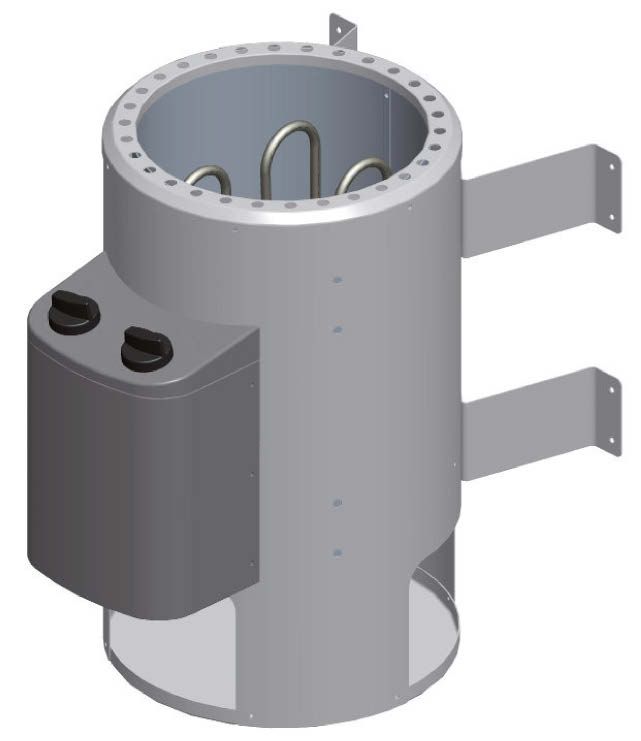
Vergleichen Sie zuerst die Material-liste mit             Vergelijk eerst de lijst van materialen                 Confrontate questa distinta materiali
Ihrem Paketinhalt! Bitte haben Sie Verständnis, dass       met de inhoud van uw pakket! Reclamaties kunnen        prima con il contenuto del pacchetto! Vi preghiamo di
Beanstandungen nur im nicht aufgebauten Zustand            alleen in behandeling worden genomen zolang de         comprendere che eventuali reclami possono essere
bearbeitet werden können!                                  onderdelen nog niet zijn gemonteerd!                   accolti solo prima del montaggio!

       First compare the list of materials with                   Start med at kontrollere materialelisten med              Nejprve překontrolujte obsah balení
your package contents! Please understand that              indholdet af den leverede pakke! Vi gør venligst       podle materiálového listu! Mějte pochopení pro to, že
complaints can be processed in the non-built status        opmærksom på at reklamationer kun kan behandles        případnou reklamací se můžeme zabývat pouze tehdy,
only!                                                      for materialer som ikke er blevet bearbejdet!          když díly nebudou smontované! Za pomoci tohoto
                                                                                                                  seznamu můžete jednotlivé díly přiřadit k montážnímu
                                                                                                                  návodu.

           Commencez par comparer la liste du                     En primer lugar, compare la lista de material
matériel avec le contenu de votre paquet! Sachez que       con el contenido del paquete. Rogamos entienda
nous traitons uniquement les réclamations concernant       que las reclamaciones sólo pueden ser tramitadas
le matériel à l’état non monté!                            antes de montar el objeto!

                                                                                             91
                                                                                     803

54 x A1 1380 x 121 x 38mm ID 26573
                                                             2 x E2       250 x 45 x 45mm          ID 3863          2 x M1      1338 x 666 x 55mm ID 26581
                                                             2 x E3       555 x 45 x 45mm         ID 40301

 1 x A2 135 x 121 x 38mm                 ID 80228
16 x A3 564 x 121 x 38mm                 ID 53531
                                                             4 x E4      2000 x 58 x 18mm ID 48545
                                                                                                                    1 x L1     1309 x 250 x 90mm ID 52066
                                                                                                                    1 x L2     1309 x 550 x 90mm ID 52064

 1 x A4      154 x 121 x 38mm            ID 80405
                                                             1 x B1       1920 x 20 x 3mm         ID 20799
                                                                                                                                   Siehe Türpaket
                                                             2 x B2      1309 x 90 x 16mm         ID 72925                         Opmerking Door Package
                                                             2 x B3       250 x 45 x 18mm         ID 26716                         Note Door Package
                                                             2 x B4       550 x 45 x 18mm         ID 26717                         Remarque Package porte
                                                             2 x B5       800 x 45 x 18mm         ID 24796                         Nota Paquete Puerta

                                                             4 x B6      1308 x 45 x 18mm         ID 26580                         Nota Door Package
                                                                                                                                   Poznámka Door balíček
                                                             2 x B7      2100 x 45 x 18mm         ID 19547
 1 x A5 1380 x 121 x 38mm ID 21867                           5 x B8      2000 x 58 x 18mm         ID 48541
                                                             1 x B9       300 x 95 x 18mm         ID 19130
                                                            4 x B10       480 x 95 x 18mm         ID 20930
                                                            4 x B11       565 x 95 x 18mm         ID 15498
                                                            2 x B12       800 x 58 x 28mm         ID 15493        1 x D1
                                                            4 x B13      1916 x 36 x 36mm         ID 21431

 1 x E1       1820 x 140 x 26mm ID 26480
10m ID 14025 1x ID 50420
50 x 4,5 x 40mm ID 26285
0RGHOO
%UDQGJHIDKU
'DV$EOHJHQYRQ*HJHQVWlQGHQRGHU7H[WLOLHQDXIGHP
6DXQDRIHQRGHUGHVVHQ$EVFKUDQNXQJHQLVWYHUERWHQ%HXQG
(QWOIWXQJV|IIQXQJHQGUIHQQLFKWYHUVFKORVVHQZHUGHQ
$QOHLWXQJEHDFKWHQ
N: 13(a9 ,QWHJULHUWH6WHXHUXQJ %LR
20 x 4 x 30mm ID 3686 N:
N:
13(a9 ([WHUQH6WHXHUXQJ )LQQLVFK
.DULEX+RO]WHFKQLN*PE+Ɣ(GXDUG6XOLQJ6WUƔ%UHPHQ
60 x 4 x 35mm ID 3687
60 x S1 4 x 30mm ID 26116 1x
350 x 4 x 40mm ID 21925
30 x 4 x 50mm ID 3688 6 x S2 12 x 18mm ID 46403
30 x 4 x 70mm ID 3689
25 x 4,5 x 80mm ID 9204
20 x 6 x 60mm ID 14014
20 x 6 x 80mm ID 47558
6x 3 x 16mm ID 46376
80 x 6 x 90mm ID 26715
Draufsicht
Top view
vue de dessus
bovenaanzicht
vista desde arriba
vista desde arriba
vista dall‘alto
půdorys
>10cm >10cmM1 M1
B6 B6
B6
B6
B8
B8 B 13 17x A 1
B 13 B8
18x A 1 B 13
E4
B7
18x A 1
A1
B8
B7
B4
E3 16x A 3 B4
L2
B3 B2
L1
B3 E3
E2 B2
B8
E2
A4
B 13
E4 E4
A2 E1
E4
B 10 B 11
B 11
B 10
B 10 B 11
B 10
B 11
B 12
B 12
B5
B501 B 13 02.1
B 13
B 13
B 13
A5 !
02.2
A4
A2
!
Achten Sie auf die gleiche Höhe
Look for the same height
Prestar atención a la misma altura
Prestare attenzione alla stessa altezza
02.3
Faites attention à la même hauteur Dávejte pozor na stejnou výšku
Besteed aandacht aan de dezelfde hoogte
Ø3mm 4×40
Ø5mm 6×90
02
(
1
A 02.1 ( 02.1 + 02.2 02.3
x 17x
18 A1
02.2
A1
02.3
6×90
!
4×40
6
A5 5 1
4 A 4×40
x 4×40
18
3
2 16x
1
A3
138x 6×90
! ! A4
A2
6×90
2 66x
103
90°
!!! A=B !!!
A
05.1
B
04 4×40 05 B6
4x B6
B6
B6
05.1
Ø3mm
1895mm
4×40
B706
!
06.1
4×40
06.2 Ø3mm
4×40
41x
06.1 06.2
Bündig!
Affleurement!
Gelijk!
Aras!
Flush!
Combacia!
Stejný!
Ø3mm
20mm
4×40
4×40
Ø3mm
B7Einbau
Einb au Saunatür Sauna deur installatie Sauna Instalace dveře
Installation de porte Sauna Instalación de la puerta Sauna
Sauna door installation Installazione porta Sauna
!!! 01 03 !!!
07
D1
08 08.1-1
4,5×80
08.1
4,5×80
08.1-2
4,5×80
S2
6x
S2
6x09 09.1 09.1
10
M1
M1
B1
11 4x
11.1
3x
11.1 3x
4x
Ø3mm
4x70
4×70
14x12 2x
B8
1980mm
13 4x
E4
1980mm
14 5x B 8 = 1980mm
B 8 = 1980mm
E 4 = 1980mm
E 4 = 1980mm
E 4 = 1980mm E 4 = 1980mm
Ø3mm
4,5×40
14.2
14.1
4,5×40
30x
14.1 4,5×40
Ø3mm
14.2
Ø3mm
4,5×4015
B8
!
B8
B8
Ø3mm
4,5×40
4,5×40
S1
12x 42x
S1
16 2x B 11 4×40
B 10 16x
B 11
B 10
Ø3mm
4x4017 a 4×35
Nur bei 9 kW-Ofen
Seulement 9 kW chauffe 16x
Only 9 kW heater
Slechts 9 kW heater
Sólo calentador de 9 kW
Solo riscaldamento 9 kW Ø3mm
4x35
Pouze topné těleso 9 kW
210mm
4x
B 5/12
B 12 = 595mm
B 12 = 595mm
595mm
B 5 = 595mm
B 5 = 595mm
17 b 4×35
Bei allen anderen Öfen
16x
Pour tous les autres fours
For all other furnaces
Voor alle andere ovens
Para todos los otros hornos Ø3mm
4x35
Per tutti gli altri tipi di forni
U všech ostatních pecích 200mm
B 12
B 12
B5
B518 18.1-1
E3
800mm
E2 500mm
Ø5mm
500mm
6x80
18.1 18.2
18.3
18.1-2 B4
B3
Ø3mm
4x40
4×40 6×80
11x 10x
18.3 18.2-1
E3
Ø3mm
B9
800mm
4x40
500mm
E2
Ø5mm
500mm
6x80
18.2-2 B4
Hier ist die Funktionsweise des Brettes Aquí está representada la forma de
abgebildet. Regeln Sie damit die Abluft nach funcionamiento de la tabla. Regule con ello el
Ihren eigenen Wünschen. aire de salida según sus propios deseos.
B3
Ceci représente le mode de Viene illustrato il principio di funzionamento
fonctionnement de la planche. Avec elle, régulez della tavoletta di regolazione della ventilazione. Ø3mm
l’écoulement de l’air selon vos désirs. Con essa si può regolare a piacere la
ventilazione.
This figure shows the functional principle of
the board. Regulate the exhaust air according to Zde je zobrazená funkce desky. Regulujte 4x40
your own wishes. s ní odsávací vzduch dle Vašeho přání.
Hier is de werking van het plankje
afgebeeld. Regel daarmee de luchtafvoer naar
eigen wens.19 2x
4×50
B2
Ø3mm
4×50
L 1/2
10x
Bündig!
Affleurement!
20 21 Gelijk!
Aras!
Flush!
Combacia!
Stejný!
E1
E1
Ø3mm
4×35
4x35
L 2/B 2
Ø3mm
L 1/B 2
B 5/10/11/12
4x35 4×35
10x 12x
Einbau
Einb au Saunatür Sauna deur installatie Sauna Instalace dveře
Sauna door installation Instalación de la puerta Sauna
STOP Installation de porte Sauna Installazione porta Sauna
!!! 04 ... !!!Installation TÜV-Schild Installation TÜV Shield Installation TÜV Shield
Installatie TÜV Shield Installazione TÜV Shield Instalación TÜV Escudo
Instalace TÜV Shield Namestitev TÜV tablice
01
!!!
Entfernen Sie die Schutzfolie vom beiliegenden
TÜV-Schild.Lassen Sie den Saunaofen von einem
zugelassenen Elektrofachmann anschließen. Dieser
markiert den installierten Ofen auf dem TÜV-Schild.
Bringen Sie das TÜV-Schild an einer gut sichtbaren
Stelle über dem Ofen an.
Remove the protective film from the accompanying
Participate Schild.Lassen connecting the heater by a
licensed electrician. This marks the installed furnace
on the TÜV sign. Attach the TÜV sign at a conspicuous
place on the stove.
Retirez le film protecteur de l‘accompagnant
Participer Schild.Lassen raccorder l‘appareil par un
électricien agréé. Ceci marque le four installé sur le
signe TÜV. Fixer le signe de TÜV à un endroit bien en
vue sur le poêle.
Verwijder de beschermfolie van de begeleidende
Deelnemen Schild.Lassen het aansluiten van de
kachel, door een erkende elektricien. Dit markeert de
geïnstalleerde oven op het TÜV teken. Bevestig de TÜV
teken op een opvallende plaats op het fornuis.
Rimuovere la pellicola protettiva dal accompagna
Partecipa Schild.Lassen collegando il riscaldatore da un
elettricista qualificato. Questo segna il forno installato sul
segno TÜV. Fissare il segno TÜV in un luogo ben visibile
sulla stufa.
Retire la película protectora de la Schild.Lassen
acompaña Participar conectar el calentador por un
electricista autorizado. Esto marca el horno instalado
en el signo TÜV. Coloque el cartel de TÜV en un lugar
visible en la estufa.
02
Odstraňte ochrannou fólii z doprovodného
Hlavní Schild.Lassen připojení ohřívače licencovaným
elektrikář. Toto označí Instalovaný pec na znamení TÜV.
Připevněte znamení TÜV na dobře viditelném místě na
sporáku.
0RGHOO
%UDQGJ
HIDKU
'DV$EOHJH
QYRQ*
HJHQVWlQG
HQRGHU
EVFKUDQNX
7H[WLOLH
QJHQLV
QDXIGH
WYHUERWHQ
HQZHUG
P
%HXQ
HQ
G
S priložene tablice odstranite zaščitno folijo. Peč
savne naj prikluči usposobljeno osebje, ki inštalirano peč
HVVHQ$ VFKORVV
IHQRGHUG QQLFKWYHU
6DXQDR QJHQGUIH
V|I IQX
(QWOIWXQJ
EHDFKWHQ
$QOHLWXQJ
označi na TÜV tablici. Tablico namestite na vidno mesto
%LR
QJ
6WHXHUX
,QWHJULHUWH )LQQLVF
K
a9 UXQJ
13( ([WHUQ
H6WHXH
N: a9
13( UHPHQ
peči.
Ɣ%
N: XOLQJ6WU
(GXDUG6
KQLN*PE+Ɣ
N: X+RO]WHF
!!!
.DULE30.09.2019
47370
Aufbauanleitung
Building Instructions
notice de montage
montagehandleiding
Montagevejledning
Instrucciones de construcción
Istruzioni per il montaggio
Montážní návod
+49 421 38693 33Vergleichen Sie zuerst die Material-liste mit Vergelijk eerst de lijst van materialen met de Confrontate questa distinta materiali prima
Ihrem Paketinhalt! Bitte haben Sie Verständnis, dass inhoud van uw pakket! Reclamaties kunnen alleen in con il contenuto del pacchetto! Vi preghiamo di
Beanstandungen nur im nicht aufgebauten Zustand behandeling worden genomen zolang de onderdelen comprendere che eventuali reclami possono essere
bearbeitet werden können! nog niet zijn gemonteerd! accolti solo prima del montaggio!
First compare the list of materials with Start med at kontrollere materialelisten med Nejprve překontrolujte obsah balení podle
your package contents! Please understand that indholdet af den leverede pakke! Vi gør venligst materiálového listu! Mějte pochopení pro to, že
complaints can be processed in the non-built status opmærksom på at reklamationer kun kan behandles případnou reklamací se můžeme zabývat pouze tehdy,
only! for materialer som ikke er blevet bearbejdet! když díly nebudou smontované! Za pomoci tohoto
seznamu můžete jednotlivé díly přiřadit k montážnímu
návodu.
Commencez par comparer la liste du matériel En primer lugar, compare la lista de material
avec le contenu de votre paquet! Sachez que nous con el contenido del paquete. Rogamos entienda
traitons uniquement les réclamations concernant le que las reclamaciones sólo pueden ser tramitadas
matériel à l’état non monté! antes de montar el objeto!
70
473
45°
50 x 4 x 40 mm ID 21925
1 x D1 2095 x 78 x 18mm ID 53617
45° 20 x 4,5 x 30 mm ID 26115
1 x D2 2095 x 78 x 18mm ID 53618 20 x ID 26116
45°
1x ID 70565
45°
1 x D3 2587 x 78 x 18mm ID 53619
2 x A1 200 x 95 x 18mm ID 28440
2 x A2 1937 x 140 x 26mm ID 28215
1 x A3 2550 x 140 x 26mm ID 1553901 ( )
A2
! ( )
4×40
01.1
) (
A3
Ø3mm A2
4×40
12x
01.1 02.1 4×40
4×40
Ø3mm
Ø3mm
02
4×40
A1 Ø3mm
02.1
4×40
A1
16x03 D2
D1
D3
Ø3mm
4,5×30
4,5×30
12x
04
07
60mm
!!!
05 06
0802.06.2021
80373
Aufbauanleitung
Building Instructions
notice de montage
montagehandleiding
Montagevejledning
Instrucciones de construcción
Istruzioni per il montaggio
Montážní návod
Karibu Holztechnik GmbH ● Eduard-Suling-Str. 17 ● 28217 Bremen info@karibu.deVergleichen Sie zuerst die Material-liste mit Vergelijk eerst de lijst van materialen Confrontate questa distinta materiali
Ihrem Paketinhalt! Bitte haben Sie Verständnis, dass met de inhoud van uw pakket! Reclamaties kunnen prima con il contenuto del pacchetto! Vi preghiamo di
Beanstandungen nur im nicht aufgebauten Zustand alleen in behandeling worden genomen zolang de comprendere che eventuali reclami possono essere
bearbeitet werden können! onderdelen nog niet zijn gemonteerd! accolti solo prima del montaggio!
First compare the list of materials with Start med at kontrollere materialelisten med Nejprve překontrolujte obsah balení
your package contents! Please understand that indholdet af den leverede pakke! Vi gør venligst podle materiálového listu! Mějte pochopení pro to, že
complaints can be processed in the non-built status opmærksom på at reklamationer kun kan behandles případnou reklamací se můžeme zabývat pouze tehdy,
only! for materialer som ikke er blevet bearbejdet! když díly nebudou smontované! Za pomoci tohoto
seznamu můžete jednotlivé díly přiřadit k montážnímu
návodu.
Commencez par comparer la liste du En primer lugar, compare la lista de material
matériel avec le contenu de votre paquet! Sachez que con el contenido del paquete. Rogamos entienda
nous traitons uniquement les réclamations concernant que las reclamaciones sólo pueden ser tramitadas
le matériel à l’état non monté! antes de montar el objeto!
73
803
1x ID 70348
1x ID 70349
1x ID 74001 1x ID 26498 6x ID 14266
Bitte beachten Sie, dass es sich bei einem Spontanbruch infolge von Nickelsulfideinschlüssen um Glasbrüche handelt, die nicht auf
!
Verarbeitungsfehler basieren und somit nicht durch den Hersteller und dem Verarbeiter zu vertreten sind. Der Spontanbruch ist als
hinzunehmendes Allgemeinrisiko anzusehen.
Bitte haben Sie Verständnis, dass wir eine Nachlieferung nur gegen Berechnung ausführen können.Einbau
Einb au Glastür Installationsglasdør
Installation of glass door Montaje de la puerta de cristal
Montage porte en verre Installazione portello di vetro
Montage van de glazen deur Sauna Instalace dveře
01 Saunatürglas in den Türrahmen legen
Put the door glass in the frame
Mettez le verre de la porte dans le cadre
Plaats het deurglas in het frame
Sæt dørglasset i rammen
Pon el vidrio de la puerta en el marco
Metti il vetro della porta nel telaio
Vložte sklo dveří do rámu
02 Saunatürglas in den Türrahmen ausrichten
Center the glass in the wooden frame
Bien aligner le verre à vitre
Lijn het glas uit in het deurframe
Juster saunaens dørglas i dørkarmen
Alinee el vidrio en el marco de la puerta
Allineare il vetro nel telaio della porta
Skleněná dvířka sauna v zárubně zarovnání
1. 2. 3.03
1895 mm
6×80
!
1.
2.Einbau
Einb au Glastür Installationsglasdør
Installation of glass door Montaje de la puerta de cristal
Montage porte en verre Installazione portello di vetro
Montage van de glazen deur Sauna Instalace dveře
04
05
Alle Verstell-Excenter müssen in der
Glasscheibe die gleiche Grundstellung haben
All adjustable eccentrics must have the same
basic adjustment in the glass panel
Tous les excentreurs de positionnement doivent
avoir la même position de base dans la vitre
Alle excentrische verstelelementen moeten in
dezelfde stand in de glasplaat worden geplaatst
Alle justeringsexcentricer skal have samme
grundlæggende position i glasruden
Todos los excéntricos regulables tienen que tener
la misma posición base en la hoja de cristal
Tutti gli eccentrici di regolazione devono avere la
stessa posizione base nella lastra di vetro
šechny nastavovací podivínů musí mít stejný
základní polohy ve skleEinbau
Einb au Glastür Installationsglasdør
Installation of glass door Montaje de la puerta de cristal
Montage porte en verre Installazione portello di vetro
Montage van de glazen deur Sauna Instalace dveře
06Einbau
Einb au Glastür Installationsglasdør
Installation of glass door Montaje de la puerta de cristal
Montage porte en verre Installazione portello di vetro
Montage van de glazen deur Sauna Instalace dveře
07 Alle Verstell-Excenter müssen in der Alle justeringsexcentricer skal have samme
Glasscheibe die gleiche Grundstellung haben grundlæggende position i glasruden
All adjustable eccentrics must have the Todos los excéntricos regulables tienen que tener
same basic adjustment in the glass panel la misma posición base en la hoja de cristal
Tous les excentreurs de positionnement doivent Tutti gli eccentrici di regolazione devono avere
avoir la même position de base dans la vitre la stessa posizione base nella lastra di vetro
Alle excentrische verstelelementen moeten in šechny nastavovací podivínů musí mít stejný
dezelfde stand in de glasplaat worden geplaatst základní polohy ve skle08
Außen: Metall
Outside: metal
Extérieur: métal
Buiten: metaal
Exterior: metal
Esterno: metallo
Venku: kov
Innen: Holz
Inside: wood
Intérieur: bois
Binnen: wood
Interior: madera
Interno: legno
Uvnitř: dřevoKaribu Artikel-Nr.: I-Nr.: Typ
Artikel-Nr.:
70445 37.467.10 15011 3,6 kW Saunaofen IS/SS - P & P
IPX42
gen, Kleinkindern, Kindern, Alter und Behinderung.
                                                                            Verhindern sie den Gebrauch durch Personen, ein-
                                                                            schließlich Kinder deren physische, sensorische oder
                                                                            mentale Fähigkeiten oder Mangel an Erfahrung und/
                                                                            oder Wissen den sicheren Gebrauch der Geräte ohne
                                                                            Aufsicht gewährleisten.
                                                                          • Verhindern sie den Gebrauch der Geräte durch Per-
                                                                            sonen, die unter Einfluss von Medikamenten, Alkohol
                                                                            oder Drogen stehen.
                                                                          • Nur mäßig Aufgießen, zu viel Wasser auf den Steinen
                                                                            kann zu Verbrühungen führen. Die Aufgussmenge soll
          Zeitvorwahl
                                                                            15 g/m³ Kabinenvolumen nicht überschreiten.
                                                                          • Benutzen Sie die Sauna nicht um Gegenstände,
                                                                            Kleidung oder Wäsche zu trocknen. Brandgefahr!
 Abb. 2
                                     Temperaturvorwahl                    • Keine Gegenstände auf dem Ofen ablegen. Brandge-
                                                                            fahr!
Allgemeines                                                               • Keine Gegenstände im Konvektionsstrom des
 Sehr geehrte Kundin, sehr geehrter Kunde, vor Anschluss und                Ofens anbringen, ausgenommen der Tempertur-
 Inbetriebnahme die Gebrauchsanweisung aufmerksam durchlesen um etwaige     fühler der Saunasteuerung.
 Schäden zu vermeiden.
                                                                          • Metalloberflächen können bei feuchten, und Meeres-
Wichtige Sicherheitshinweise.                                               Klima rosten.
• Die Montage und der elektrische Anschluss der Sau-                      • Der Ofen kann in der Aufheizphase und im Betrieb
  na-Einrichtung und anderer elektrischer Betriebsmit-                      Knackgeräusche erzeugen (Metall, Heizstäbe und
  tel dürfen nur durch einen zugelassenen                                   Steine dehnen sich aus).
  Elektro-Fachmann erfolgen. (Ausgenommen P & P)                          • Sauna-Einrichtungen und Saunakabinen dürfen nur
• Zu beachten sind die notwendigen Schutzmaßnah-                            aus geeignetem, harzarmen und unbehandelten Ma-
  men nach VDE0100 § 49DA/6 und VDE 0100 Teil                               terialien (z.B. Nordische Fichte, Pappel oder
  703/11.82 §4. Auch bei Beachtung der notwendigen                          Linde) hergestellt werden.
  Schutzmaßnahmen können nicht alle Unfallrisiken                         • Die zulässige Höchsttemperatur für Wand- und De-
  ausgeschlossen werden.                                                    ckenoberfläche der Saunakabine beträgt
• Um einen gefahrlosen Betrieb Ihres Gerätes sicher-                        + 140°Celsius.
  zustellen, sollten Sie unbedingt die Sicherheitshin-                    • Mit der Zeit dunkeln die Kabinenwände im Bereich des
  weise beachten.                                                           Saunaofens stärker als im Rest der Kabine, dies ist
• In der Saunakabine darf nur ein Saunaheizgerät                            normal. Reklamationen werden nicht erstattet.
  mit entsprechender Heizleistung montiert werden.                        • Die Höhe in der Saunakabine muss min. 1,75 m
  Wir empfehlen: (siehe Tabelle).                                           betragen.
       Anschlußleistung                      Kabinengröße                 • In jeder Saunakabine sind Be- und Entlüftungsöffnun-
                                                                            gen vorzusehen. Die Belüftungsöffnung muss an der
                                                                            Wand, direkt unter dem Saunaofen ca. 5-10cm
              3,6 kW                             bis ca. 6 m3               über dem Boden sein. Die Abluftöffnung muss diago-
                                                                            nal zum Ofen im Bereich zwischen oberer und unterer
• Das Gerät ist nicht für den Gebrauch in öffentlichen                      Saunaliege in der Rückwand angeordnet sein. Die
  Saunen konzipiert.                                                        Be- und Entlüftungen dürfen nicht verschlossen wer-
• Achtung Verbrennungsgefahr. Das Gehäuse des                               den. Die Kabinenbeleuchtung mit der dazugehörenden
  Saunaofens sowie die Steine werden heiß.                                  Installation muss in der Ausführung “spritzwasser-
• Bei unsachgemäßer Montage besteht Brandgefahr.                            geschützt” und für eine Umgebungstemperatur von
  Lesen Sie bitte diese Montageanweisung sorgfältig                         140 °C geeignet sein. Daher ist in Verbindung mit dem
  durch. Beachten Sie besonders die                                         Saunaofen nur eine geprüfte Saunaleuchte mit
  Maßangaben und Hinweise.                                                  max. 40 Watt zu installieren.
• Nur die für den Saunagebrauch zugelassenen                              • Dieses Gerät kann von Kindern ab 8 Jahren und dar-
  Saunasteine verwenden. Saunasteine locker einle-                          über sowie von Personen mit verringerten physischen,
  gen, bei zu dicht gepackten Saunasteinen                                  sensorischen oder mentalen Fähigkeiten oder Mangel
  besteht Überhitzungsgefahr.                                               an Erfahrung und Wissen benutzt werden, wenn sie
                                                                            beaufsichtigt oder bezüglich des sicheren Gebrauchs
• Der Betrieb ohne Saunasteine ist nicht gestattet.                         des Gerätes unterwiesen wurden und die daraus resul-
• Halten Sie Kinder vom Saunaofen fern, Verbren-                            tierenden Gefahren verstehen. Kinder dürfen nicht mit
  nungsgefahr!                                                              dem Gerät spielen. Reinigung und Benutzer-Wartung
• Ärztlichen Rat über Saunatemperatur und Sauna-                            dürfen nicht von Kindern ohne Beaufsichtigung durch-
  dauer einholen bei gesundheitlichen Einschränkun                          geführt werden.                                     3
Montageanweisung
Maße des Saunaofens:
Achtung! Länge: 280 mm
Tiefe: 370/460 mm
Unter dem Ofen keine Bodenbeläge aus brennbarem Material wie Holz,
Kunststoffbeläge o. Ä. verwenden! Zweckmäßig im Saunabereich sind Höhe: 460 mm
Keramikfliesen. Im Bereich unter dem Ofen kann es auch auf nicht brenn-
baren Bodenbelägen oder Fugenmaterial zu Verfärbungen kommen. Es
wird kein Ersatz für Verfärbungen oder Schäden am Bodenbelag oder an
der Saunawand geleistet. Der Ofen muss vor der Wandmontage elektrisch
angeschlossen werden. Der Saunaofen ist für Kabinengrößen bis zu 6m³
konzipiert.
Montage des Saunaheizgerätes
• 4 Stück Wandhalterung laut Abbildung 3 montieren.
• Saunaofen vor die Lufteintrittsöffnung stellen. Wandhalterung Saunaheizge-
rät mittels der beigefügten Holzschrauben an der Kabinenwand befestigen.
Steinrost einlegen und Saunasteine auflegen (siehe Beschreibung “Stein- Abb. 5
rost mit Saunasteinen belegen”, Kap. “Reinigung und Pflege”).
• Bei der Montage des Saunaofens ist darauf zu achten, dass der senkrechte Hinweis:
Abstand zwischen Oberkante Saunaofen und Saunadecke mindestens 110 Bereits einmaliger Fehlanschluss kann die Steuereinrichtung zerstören.
cm beträgt, der waagerechte (seitliche) Abstand zwischen Ofen und Kabi- Bei Falschanschluss erlischt der Garantieanspruch.
nenwand mindestens 7 cm beträgt. Der Abstand zwischen Ofenunterkante
und Fußboden ist durch die Bauart der Geräte (Stellfuß) vorgegeben. Der Anleitung für den Elektroinstallateur:
Abstand zwischen Ofenrückwand und Kabinenwand ist ebenfalls durch die Für den Anschluss des Ofens und alle elektrischen Anlagen sind die DIN VDE
Bauart (Wandhalte rung) vorgegeben. 0100 und die Unfallverhütungsvorschrift BGV A2 einzuhalten. Es ist bauseits
• Der Abstand zwischen Ofenschutzgitter bzw. Liegebank und anderer brenn- eine externe, allpolige Trennvorrichtung mit voller Abschaltung entsprechend der
barer Materialien zum Ofen muss mindestens 7 cm betragen. Die Schutz- Überspannungskategorie III vorzusehen.
gitter-Höhe muss mit der vorderen Ofenhöhe gleich sein.
Achtung:
Netzanschlussleitungen müssen polychlorophren-ummantelte flexible Leitungen
sein. Anschlussleitungen nicht im Lieferumfang enthalten! Alle Leitungen, die
im Inneren der Kabine verlegt werden, müssen für eine Umgebungstemperatur
von mindestens 140 °C geeignet sein. Zu verwenden sind temperaturbestän-
dige Silikonleitungen. Den Mindestquerschnitt der Anschlussleitung und die
Mindestgröße der Saunakabine entnehmen Sie der Tabelle (S.5 Tab.1). Ein
Anschlussplan ist auf der Innenseite der Schaltschachtabdeckung angebracht.
Beachten Sie, dass stromführende Leitungen aus Sicherheitsgründen nicht
sichtbar an Kabineninnenwände verlegt werden müssen. Bei vorgefertigten
Saunakabinen sind im Wandelement mit der Zuluftöffnung meist Leerrohre oder
ein Schacht zur Kabelverlegung vorhanden. Sollte Ihre Kabine keine Vorberei-
tung zur Kabelverlegung haben, wird empfohlen an der Kabinenaußenseite eine
Anschlussdose (nicht im Lieferumfang enthalten) zu installieren. Bohren Sie
neben der Kabeleinführung des Ofens und der Anschlussdose ein Loch in die
Kabinenwand. Führen Sie das Kabel durch das Loch nach außen zur Anschluss-
dose. Alle Kabel müssen vor Beschädigung geschützt werden. Dies kann mit
Installationsschacht/- Rohren oder mit Holzabdeckleisten erfolgen.
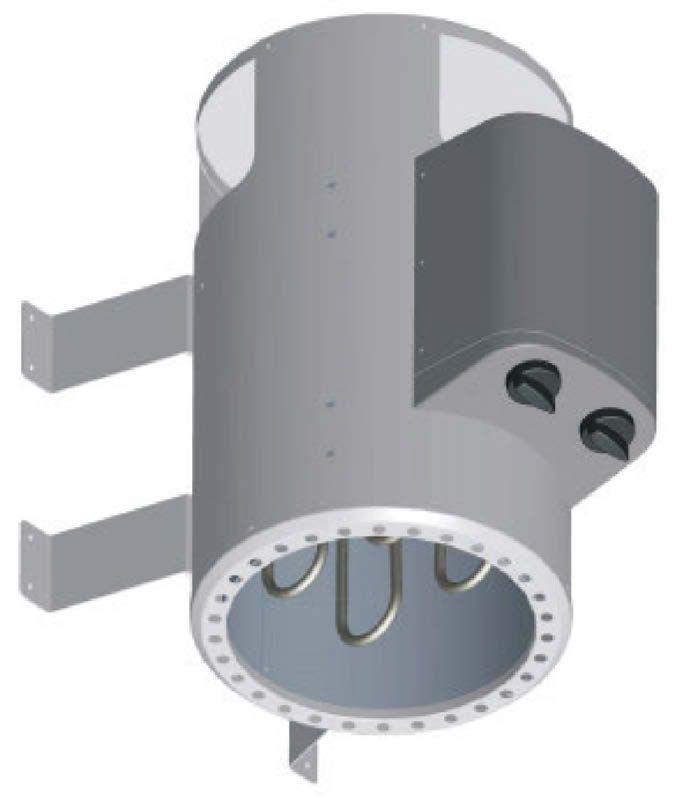
Anschlußplan
Abb. 3
3,6 kW Saunaofen interne Steuerung
Abb. 4
Prüfung de Isolationswiderstandes:
Mit einem Isolationswiderstandsmessgerät können die Widerstandswerte
zwischen den einzelnen Leiterklemmen und Gehäuse (Schutzerde) gemessen
werden. Der gesamt Isolationswiderstand zwischen Leiterklemmen und Gehäuse
(Schutzerde) muss auf jeden Fall größer 1MOhm sein.
4Gerätetyp geeignet für Mindest-Querschnitte in mm² (Kupferleitung)
Anschluß-
Kabinengröße 3,6 kW Saunaofen - Anschluß an 230 V 1N
leistung in kW in m³
Netzzuleitung
zum Steuergerät Absicherung in Ampere
3,6 kW Saunaofen 3,6 ca. 6 P&P 16
interne Steuerung
Auflegen der Saunasteine auf den Steinrost: • Nur mäßig Aufgießen, zu viel Wasser auf die Steine kann zu Verbrühungen
Saunasteine sind ein Naturprodukt! Es wird empfohlen die Steine vor dem führen.
Auflegen auf den Ofen mit klarem Wasser zu reinigen. Verwenden Sie keine • Aufguss nach allgemeinem Wohlbefinden, die Aufgussmenge soll jedoch
Steine die nicht für den Saunagebrauch vorgesehen sind. Max. 12 Kg Steine 15 g/m³ Kabinenvolumen nicht überschreiten.
verwenden. Achtung! Steine locker einlegen, sortieren Sie zu kleine Steine aus. • Der Aufguss erfolgt direkt auf die heißen Steine im Ofen und muss
Zu dicht gepackte Steine behindern die Luftzirkulation und führen zur Überhit- gleichmäßig über die Steine verteilt werden.
zung des Saunaofens und der Kabinenwände, Brandgefahr! Betreiben Sie den • Bei der Verwendung von Aufgusskonzentraten (z.B. ätherische Öle) müssen
Ofen nicht ohne Steine! Verwenden Sie nur Steine die im Handel als die Hinweise des Herstellers beachtet werden.
Saunasteine gekennzeichnet sind. Garantieansprüche werden nicht gewährt, • Bei Verwendung zu hoher Konzentrationen dieser Mittel kann es zu
bei Verwendung anderer Steine, als solche die für den Saunagebrauch vorge- Verpuffungen kommen.
sehen sind, sowie für Schäden durch unsachgemäße Befüllung der Steinkam- • Aufgüsse mit Beimischungen von alkoholischen Getränken oder sonstige
mer. Legen Sie die Steine min. 1x jährlich um, sortieren Sie zu kleine nicht für den Saunabetrieb vorgesehene Zusätze sind wegen Brand- Explo-
Steine aus und entfernen Sie angefallenen Steinstaub bzw. Gesteinssplitter. sions- und Gesundheitsgefahr nicht zulässig.
Es wird empfohlen die Steine alle 2 Jahre auszutauschen. • Bei Nichtbeachten der oben aufgeführten Punkte erlischt der
Auchtung: Garantieanspruch!
Bedecken des Ofens und unsachgemäß gefüllter Steinbehälter verursachen
Brandgefahr. Ofen nicht ohne Saunasteine betreiben! Achtung!
Aufgussmittel können Flecken auf Metalloberflächen und Saunasteinen
verursachen. Saunaaufgussmittel mit Citrusduft können aufgrund des Säu-
reanteils Rostflecken verursachen.
Verwenden Sie für den Aufguss jedoch nur Aufgussmittel in der vom
Hersteller vorgesehenen, verdünnten Form.
Verwenden Sie niemals Alkohol oder sonstige nicht für den Saunabetrieb
vorgesehene Zusätze als Aufgussmittel!
Was tun bei Problemen?
Der Ofen heizt nicht …
• Haben Sie alle notwendigen Schalter betätigt?
• Hat die Sicherung in der Hausinstallation ausgelöst?
• Haben Sie die Temperaturregler richtig eingestellt?
• Haben Sie die Zeitschaltuhr vorgewählt.
• FI-Schalter löst aus, siehe Absatz Prüfung Isolationswiderstand
Der Ofen verursacht „Knackgeräusche“
• Beim Aufheizen oder im Betrieb dehnen sich die Gehäuseteile und Heiz-
stäbe aus. Die Heizstäbe können Saunasteine verschieben und Geräusche
verursachen. „Knackgeräusche sind normal und sind kein Grund zur Rekla-
mation.
Reinigung und Pflege: Saunateine zerspringen, verursachen Geruch
Vor dem Reinigen den Ofen ausschalten und abkühlen lassen. Zur Reinigung • Nur die vom Hersteller empfohlenen oder als Saunasteine gekennzeichne-
und Pflege des Ofens sollten keine scheuernden Reinigungsmittel verwendet ten Steine verwenden.
werden. • Saunasteine überaltert, Steine austauschen.
Kabine wird nicht ausreichend warm
Aufguss: • Saunaofen zu klein dimensioniert
Der Saunaofen ist für Saunaaufgüsse geeignet. • Zu hoher Temperaturverlust der Saunakabine z.B. durch mangelhafte oder
fehlende Abdichtungen.
• Fehlanzeige des Saunathermometers. Thermometer höher und mit ca. 3 cm
Beachten Sie folgende Hinweise: Abstand zur Saunawand montieren.
• Verwenden Sie nur Wasser das die Qualitätsansprüche für Haushaltswasser • Defekt eines Heizstabes (Heizstab glüht nicht) von einer Elektrofachkraft
erfüllt. prüfen und durchmessen lassen.
• Bei Verwendung kalk- bzw. eisenhaltigen Wassers entstehen Rückstände auf
den Steinen, Metalloberflächen und im Wasserbehälter.
• Um die Gefahr von Verbrühung durch den beim Aufgießen aufsteigenden
heißen Dampf zu vermeiden, sollten Aufgüsse immer von der Seite mit einer
Schöpfkelle erfolgen.
• Durchtropfendes Aufgusswasser kann dauerhafte Verunreinigungen auf dem
Kabinenboden verursachen.
5GB
• Do not allow the sauna stove to be used by people
who are under the influence of medication, alcohol or
drugs.
• Pour small amounts of liquid on to the stones; if you
pour too much liquid on to them you may suffer scalds.
The quantity of liquid on the stones should not exceed
15 g/m³ of cabin volume.
• Do not use the sauna to dry items, clothing or laundry.
They may catch fire.
• Do not place any items on the stove. They may catch
fire.
• Do not place any items, apart from the sauna control-
Time preselection
Zeitvorwahl
ler’s temperature sensor, in the convection current of
the stove.
Fig. 2 Temperaturvorwahl
• Metal surfaces may rust in a damp, saltwater climate.
Temperature preselection
• The stove may generate cracking noises while it is
General: heating up and while it is operating (metal heating
Dear Customer, elements and stones expanding)
Please read these operating instructions carefully before you connect and use • Sauna equipment and sauna cabins may only be
the sauna stove for the first time to prevent causing any damage. made of suitable, low resin and untreated materials (for
Important safety instructions example Norway spruce, poplar or linden).
• The installation and electrical connection of the sauna • The maximum temperature for the wall and ceiling of
equipment and other electrical equipment may only be the sauna cabin is +140°C.
carried out by a licensed electrician. (except P & P) • Over time the cabin walls will become darker near the
• Refer to the safety actions required by VDE 0100 § 49 sauna stove than in the rest of the cabin; this is nor-
DA/6 and VDE 0100 Part 703/11.82 §4. Even if you mal. Complaints about this will not be accepted.
comply with the required safety actions it is not • The minimum height of the sauna cabin must be 1.75m
possible to rule out the possibility of all accident risks. (interior height)
• Follow the safety instructions to the letter to ensure • Ventilation openings must be provided in every sauna
that you can operate your equipment safely. cabin. The ventilation opening must be on the wall
• Only one sauna stove with the appropriate heating directly below the sauna stove approx. 5-10 cm
capacity may be installed in the sauna cabin. above floor level. The waste air must be discharged
(See table) through an opening diagonally opposite the stove in
the rear wall between the top and bottom benches.
Connection rating cabine size The ventilation openings must not be sealed. The
cabin light and its installation must have a splash-proof
3,6 kW up to approx. 6 m3 design and be suitable for an ambient temperature of
140°C. Therefore only an approved sauna light with
• The unit is not designed for use in public saunas. max. 40W may be installed with the sauna stove.
• Caution – danger of burns. The case on the sauna • This equipment can be used by children of 8 years
stove and the stones get very hot. and older and by people with limited physical, sensory
or mental capacities or those with no experience and
• If it is not installed correctly the unit may cause a fire. knowledge if they are supervised or have received
Read the complete assembly instructions with due instruction in how to use the equipment safely and
care. Pay particular attention to the dimensions and understand the dangers which result from such use.
instructions. Children are not allowed to play with the equipment.
• Only use sauna stones approved for use in saunas. Unless supervised, children are not allowed to clean
Insert sauna stones loosely; if the stones are inserted the equipment or carry out user-level maintenance
too tightly there is a danger of overheating. work.
• Do not operate the stove without sauna stones.
• Keep children away from the sauna stove. They may Installation instructions
suffer burns. Important.
• Seek medical advice about the sauna temperature Do not use any floor coverings under the stove if they are made of
inflammable material such as wood, plastic, etc. Ceramic tiles are ideal for use
and how long people with medical problems, infants, in a sauna.
children, pensioners and handicapped people The area under the stove may suffer discoloration, even on non-flammable
may stay in the sauna. flooring or joint material.
No compensation will be paid for discoloration or damage to flooring or the
sauna walls.
6GB
The distance between the rear of the stove and the cabin wall depends on
the design (wall mounting).
The stove must be connected to the electricity supply before it is mounted on Dimensions of the sauna stove:
the wall holder. Length: 280 mm
The sauna stove is designed for cabin sizes up to 6m³. Depth: 370/460 mm
Height: 460 mm
Installing the sauna oven
• Mount 4 wall brackets in accordance with Fig. 3.
• Place the sauna stove in front of the air inlet opening. Use the supplied
wood screws to secure the wall bracket for the sauna stove to the cabin
wall. Insert the stone grid and place the sauna stones on top (see the
description in „Loading the sauna grid with sauna stones“, section „Cleaning
and care“).
• When mounting the sauna stove on the wall, make sure that there is a Fig. 5
vertical distance of at least 110 cm between the top edge of the sauna stove
and the sauna ceiling and a horizontal distance of at least 7 cm between Note:
the stove and the cabin wall. The distance between the bottom edge of the The control equipment may be destroyed even if it is incorrectly connected
stove and the floor depends on the equipment‘s design (adjustable foot). only once. The warranty will be voided if the electrical connection is not
Similarly, the distance between the rear of the stove and the cabin wall correct.
depends on the design (wall bracket).
• The distance from the stove‘s safety grille or bench and other combustible
materials to the stove must be at least 7 cm. The safety grille height must
Instructions for the electrician
DIN VDE 0100 and Accident Prevention Regulation BGV A2 must be observed
be the same as the height of the stove at the front.
for connecting the stove and all electrical systems. An external all-pole
disconnecting device with full isolation according to overvoltage category III must
be installed.
Important:
Mains connection leads must be flexible cables with polychlorophene sheaths.
No connection leads are supplied with the stove. All the cables installed inside
the cabin must be capable of withstanding temperatures of at least 140 °C.
Heat-resistant silicon cables must be used. The minimum cross-section of the
connection cable and the minimum size of the sauna cabin are shown in the
table (page 5 Table 1). A connection diagram is affixed to the inside of the duct
cover. Please note that for safety reasons live cables are not allowed to be routed
visibly along the internal walls of the cabin. In prefabricated sauna cabins the wall
element with the air supply opening generally has empty cable conduits or a duct
for routing the cable. If your cabin does not have any cable routing preparations,
we recommend that you install a connection socket (not supplied) to the outside
of the cabin. Drill a hole in the cabin wall near the cable infeed from the stove
and the connection socket. Thread the cable through the hole to the external
connection socket. All cables must be protected from damage. This can be
achieved using installation ducting/piping or using wooden covers.
Fig. 3
Connection diagram
3.6 kW sauna stove with internal controller
Fig. 4
Test the insulation resistance
The resistance values between the various conductor terminals and the case
(protective earth) can be measured using an insulation resistance measuring
unit. The total insulation resistance between the conductor terminals and case
(protective earth) must definitely be greater than 1 MOhm.
7GB
Oven type Connection Suitable for Minimum cross-sections mm2 (copper cable)
rating in booth size 3,6kW oven connect to 230 V 1N
kW in m3
Mains cable from mains
to control unit Fuse in A
3.6 kW sauna stove 3,6 approx 6 P&P 16
Internal controller
be spread evenly over all the stones.
Position the sauna stones on the stone grid
Sauna stones are a natural product. We recommend that you clean the stones • If you use liquid concentrates (for example essential oils), follow the
with clean water before placing them on the stove. Do not use stones unless instructions for use provided by the manufacturer.
they are designed for use in a sauna. Use a maximum of 12 kg of stones. • Using excessive concentrations of these products may result in explosions.
Important. Position the stones loosely and remove any stones that are too • Do not use mixtures of alcoholic drinks or other additives not recommended
small. If the stones are packed too tightly they will affect the air circulation and for use in saunas as they pose a risk of fire, explosion and may be harmful.
will result in the sauna stove and cabin walls overheating and a fire risk. • The warranty will be voided if you fail to follow these instructions.
Do not use the stove without stones.
Only use stones that are marked as sauna stones in shops. Warranty claims Important. Liquids may cause marks on metal surfaces and sauna stones.
will not be accepted if stones other than those designed for use in saunas are Sauna liquids with citrus fragrance may cause rust patches as a result of their
used or for claims resulting from filling of the stone chambers incorrectly. Turn
acid content.
the stones at least once per year, remove any stones that are too small and
remove all stone dust and stone splinters. We recommend that you replace the In this case you should only use products in the diluted form specified by the
stones every two years. manufacturer.
Important. Troubleshooting
If you cover the stove and fill the stone container incorrectly the unit may
cause a fire. Do not use the stove without sauna stones. The stove will not heat up
• Have you activated all the necessary switches?
• Has the fuse in the domestic installation tripped?
• Have you set the temperature controller correctly?
• Have you pre-set the time switch?
• RCCB trips – see the section entitled “Testing the insulation resistance”
The stove causes “cracking noises”
• The case parts and heating elements expand when the stove is heating up or
operating. The heating elements may move the sauna stones and cause
noises. Cracking noises are normal and are not grounds for complaint.
• Sauna stones split and cause an odor
• Use only sauna stones recommended by the manufacturer.
• Sauna stones are too old; replace them.
The cabin does not get hot enough
• The sauna stove is too small
• Excessive temperature loss from the sauna cabin, for example due to poor or
lack of sealing.
• Incorrect display on the sauna thermometer. Mount the thermometer higher
and at a distance of approx. 3 cm from the sauna wall.
• Have a defective heating element (heating element does not glow) checked
and measured by an electrician.
Cleaning and care
Switch off the stove and allow it to cool before you clean it.
Do not use scouring cleaning products to clean the stove.
Liquids
The sauna stove is suitable for sauna liquids.
Please read the following carefully:
• Only use water that meets the quality requirements for domestic water.
• Water that contains high levels of lime or iron will leave residue on the
stones and metal in the water tank.
• To prevent scalds caused by rising steam whilst pouring liquid over the
stones, liquids should always be poured from the side using a ladle.
• Dripping water may cause permanent marks on the cabin floor.
• Pour small amounts of liquid on to the stones; if you pour too much liquid on
to them you may suffer scalds.
• Use as much liquid as you are comfortable with, but do not exceed a volume
of 15 g/m³ of cabin volume.
• The liquid should be poured straight on to the stones in the stove and must
8F
• Demandez un conseil médical sur la température et la
durée du sauna en cas de problèmes de santé, pour
les jeunes enfants, les enfants, les personnes âgées
ou handicapées.
• N‘arrosez pas trop, une trop grande quantité d‘eau
sur les pierres peut entraîner une brûlure par liquide
chaud. La quantité de projection d’eau ne doit pas
dépasser 15g/m³ du volume de la cabine.
• N‘utilisez pas le sauna pour faire sécher des objets,
des vêtements ou du linge. Risque d‘incendie !
• Ne posez pas d‘objet sur le poêle. Risque d‘incendie !
Présélection du temps
Zeitvorwahl
• Ne placez pas d‘objet dans le courant de convection
du poêle, sauf le
capteur de température de la commande du sauna.
Fig. 2
Temperaturvorwahl
Présélection de la température • Les surfaces métalliques peuvent rouiller dans un
climat humide et océanique.
Généralités • Il est possible que le poêle fasse du bruit (craquement)
Chère Cliente, Cher Client, pendant sa phase de réchauffement (les bâtons de
Veuillez, avant le raccordement et la mise en service, lisez chauffage métalliques et les pierres se dilatent)
consciencieusement ce mode d‘emploi pour éviter tout dommage. • Les installations et les cabines de sauna doivent
Consignes de sécurité importantes exclusivement être fabriquées en matériaux adéquats
• Le montage et le raccordement électrique du dispositif sans résine et non traités (p. ex. l‘épicéa nordique, le
de sauna et d‘autres matériaux d‘exploitation peuplier ou le tilleul).
électriques doivent uniquement être effectués par • La température la plus élevée admise pour la surface
un(e) spécialiste en électricité dûment autorisé(e). des murs et du plafond de la cabine de sauna s‘élève
(excepté P & P) à +140 °C.
• Respectez absolument les mesures de protection • Avec le temps, les parois de la cabine s‘assombrissent
selon VDE 0100 § 49DA/6 et VDE 0100, partie dans la zone du poêle de sauna plus que dans le reste
703/11.82 §4. Même lorsque toutes les mesures de de la cabine, c‘est normal. Les réclamations ne sont
protection nécessaires sont respectées, il est impos pas remboursées.
sible d‘exclure complètement tout risque d‘accident. • La hauteur de la cabine du sauna doit s‘élever au
• Afin d‘assurer un fonctionnement de votre appareil moins à 1,75 m .
sans danger, vous devez absolument respecter les • Il faut prévoir des bouches d‘aspiration et de refoule-
consignes de sécurité dans le chapitre correspondant. ment dans chaque cabine du sauna. Le trou d‘aéra-
• Dans la cabine du sauna, on doit monter un seul poê tion doit se trouver sur le mur, juste sous le poêle de
le de sauna avec une puissance de chauffage corres sauna, à environ 5 à 10 cm au-dessus du sol. L‘orifice
pondante (voir tab.). d‘air sortant doit être placé diagonalement par rapport
Puissance absorbée Surface de la cabine au poêle, dans la zone entre la couche supérieure et la
couche inférieure, dans la paroi arrière. Les bouches
d‘aspiration et de refoulement ne doivent pas être
3,6 kW Jusqu’à env. 6 m3 obturées. L‘éclairage de la cabine avec l‘installation
correspondante doit être « protégé contre les
• L‘appareil ne convient pas à l‘emploi dans des projections d‘eau » dans le modèle et approprié pour
saunas publics une température ambiante de 140° C. Par conséquent,
• Attention, risque de brûlure. Le boîtier du poêle de il faut installer -en relation avec le poêle de sauna-
sauna et les pierres deviennent brûlantes. uniquement une lampe pour sauna contrôlée de
• Il existe un danger d‘incendie dû à un montage non maxi. 40 watts
conforme aux règles de l‘art. Veuillez lire les instruc- • Cet appareil peut être utilisé par les enfants à partir
tions de montage avant de l‘utiliser pour la première de 8 ans et les personnes avec des capacités
fois. Respectez particulièrement les cotes et les physiques, sensorielles ou intellectuelles diminuées
consignes suivantes. ou en manque d’expérience et de connaissances à
• Utilisez exclusivement des pierres de sauna homolo- condition qu’ils soient surveillés ou aient reçu les
guées pour l‘emploi en sauna. Placez les pierres du instructions relatives à l’utilisation sûre de l’appareil et
sauna sans forcer, lorsqu‘elles sont trop serrées, il y qu’ils comprennent les risques résultant de cette
a risque de surchauffe. utilisation. Les enfants n’ont pas le droit de jouer avec
• Le fonctionnement sans pierres du sauna n‘est pas l’appareil. Les enfants ne doivent pas effectuer le
autorisé. nettoyage et la maintenance de l’utilisateur sans
• Maintenez les enfants à l‘écart de poêles de sauna, surveillance.
risque de brûlures !
9F
Instructions de montage
Attention ! Dimensions du poêle pour sauna :
N‘utilisez aucun revêtement de sol en matériau inflammable (bois, matières
Longueur : 280 mm
plastiques ou autres) sous le poêle ! Les carreaux de céramique sont
fonctionnels dans les saunas. Profondeur : 370/460 mm
Dans la zone sous le poêle, les revêtements de sol non inflammables ou le Hauteur : 460 mm
matériau de jointoiement peuvent changer de couleur.
Les revêtements du sol ou le mur du sauna dont la couleur a changé ou ceux
endommagés ne seront pas remplacés.
L‘écartement entre la paroi arrière du poêle et le mur de la cabine est prévu
par le type de construction (support mural).
Le poêle doit être raccordé électriquement sur la fixation murale avant le
montage.
Le poêle pour sauna est conçu pour des tailles de cabines allant jusqu‘à 6m³. Fig. 5
Montage de l’appareil de chauffage
pour sauna Remarque:
Le dispositif de commande peut être détruit par un mauvais raccordement.
• Montez les 4 fixations murales selon l‘illustration. La garantie devient caduque en cas de mauvais raccordement.
• Placez le poêle pour sauna devant l‘ouverture d‘entrée d‘air. Fixez la
fixation murale de l‘appareil de chauffage du sauna à l‘aide des vis à bois
fournies à la paroi de la cabine. Introduisez la grille pour les pierres et dépo- Instructions pour l‘électricien(ne)
sez les pierres du sauna (voir description « Couvrir la grille pour les pierres Pour raccorder le poêle et toutes les installations électriques, il faut respecter la
avec les pierres »,chap. « Nettoyage et entretien »). directive DIN VDE 0100 et la directive de prévention des accidents BGV A2.. Le
• Lors du montage du poêle pour sauna, il faut veiller à ce que l‘écart vertical client doit prévoir un dispositif externe de séparation pour tous les pôles à mise
entre l‘arête supérieure du poêle et le plafond du sauna soit d‘au minimum hors circuit complète, conformément à la catégorie de surtension III.
110 cm, l‘écart horizontal (latéral) entre le poêle et la paroi de la cabine doit
être d‘au minimum 7 cm. L‘écart entre l‘arête inférieure du poêle et le sol Attention
est imposé par la conception des appareils (pied d‘appui). L‘écart entre la Les câbles de raccordement secteur doivent être des câbles souples enveloppés
paroi arrière du poêle et la paroi de la cabine est également imposé par la de polychloroprène. Les câbles de raccordement ne sont pas compris dans la
conception (support mural). livraison ! Tous les câbles posés à l‘intérieur de la cabine doivent être appropriés
• L‘écart entre la grille de protection du poêle ou le banc et d‘autres matériaux à une température ambiante d‘au moins 140 °C. Il convient d‘utiliser des câbles
combustibles par rapport au poêle doit être d‘au minimum 7 cm. La hauteur en silicone résistants à la chaleur. La section transversale minimale du câble de
de la grille de protection doit être identique à la hauteur avant du poêle. raccordement et la taille minimale de la cabine du sauna figurent dans le tableau
(p. 5 tabl. 1). Un schéma des connexions est apposé sur la face interne du
recouvrement de la boîte de commutation. Pour des raisons de sécurité, veillez à
ce que les câbles électriques restent invisibles au niveau des parois internes de
la cabine. Lorsqu‘il s‘agit de cabines de sauna préfabriquées, celles-ci comport-
ent la plupart du temps des gaines ou une conduite vide pour la pose des câbles
dans l‘élément mural avec l‘ouverture d‘entrée d‘air. Si votre cabine n‘est pas
préparée pour la pose des câbles, nous recommandons d‘installer une prise de
raccordement sur la partie extérieure de la cabine (non compris dans la livrai-
son). Percez un trou dans la paroi de la cabine à côté de l‘entrée du câble du
poêle et de la prise de raccordement. Faites passer le câble à travers le trou vers
l‘extérieur pour le brancher sur la prise de raccordement. Tous les câbles doivent
être protégés de l‘endommagement. Pour ce faire, on peut utiliser des gaines ou
des conduites d‘installation ou recouvrir les câbles par des baguettes de bois.
Schémas des connexions
Commande interne du poêle pour sauna 3,6 kW
Fig. 3
Fig. 4 Contrôle de la résistance d‘isolement :
On peut mesurer les valeurs de résistance de l‘isolement entre chacune des
bornes de conducteur et le boîtier (terre de protection) à l‘aide d‘un appareil de
mesure approprié. La résistance d‘isolement totale entre les bornes de
connecteur et le boîtier (terre de protection) doit en tout cas être supérieure à
1MOhm.
10Sie können auch lesen