319 x 264 x 290 cm Gartensauna COUNTRY - Montageanleitung - sentiotec
←
→
Transkription von Seiteninhalten
Wenn Ihr Browser die Seite nicht korrekt rendert, bitte, lesen Sie den Inhalt der Seite unten
Montageanleitung
Assembly instructions

   DE
   EN
   FR
   FI

Gartensauna             COUNTRY
                        319 x 264 x 290 cm

Version 10/17                         Ident-Nr. 1-030-307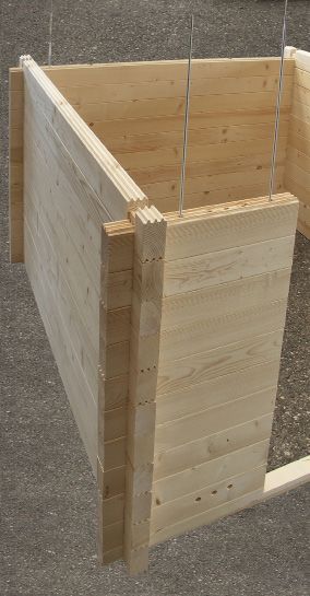
Montageanleitung

         DE
Gartensauna
COUNTRY

     Außenmaß: 319 x 264 x 290 cm
     Innenmaß: 200 x 200 x 210 cm
     Wandstärke: 70 mm

Sehr geehrter Kunde,

Kontrollieren Sie, bevor Sie mit der Arbeit beginnen, anhand der Stückliste, ob alle Einzelteile auch tatsächlich
mitgeliefert wurden. Sollten Einzelteile ausnahmsweise fehlen, benachrichtigen Sie spätestens 14 Tage nach Erhalt
der Kabine Ihren Händler.

Heben Sie den Lieferschein, die Rechnung und die Montageanleitung für even-
tuelle Rückfragen gut auf.

Sie benötigen folgendes Werkzeug:

1 Hammer mit Beilageholz oder einen.Gummihammer
1 Akkuschrauber mit Bits für Kreuzschrauben und Torx
1 Rollmaßband
1 Bohrer Ø10 mm; 1 Bohrer Ø3 mm
1 Wasserwaage
1 Bleistift

Für die Montage benötigen Sie einen Helfer! Weiters empfehlen wir die Löcher für die
Schrauben vorzubohren.

 !    Der Elektroanschluss darf nur durch eine Elektrofachkraft oder eine vergleichsweise qualizierte
      Person ausgeführt werden.

                             Geringfügige Maßabweichungen können möglich sein.
                             Technische Änderungen und Druckfehler vorbehalten.

02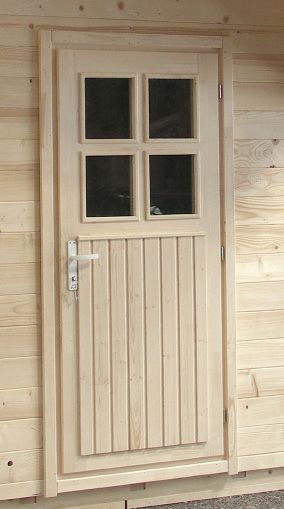
Stückliste COUNTRY

Vorderseite mit Türe                                          Bodenrahmen 206 x 8 x 4 cm
                                                             3
                                                             2 Bodenrahmen 206 x 12 x 4 cm
   Blockbohle 230 x 6,5 x 7 cm mit Ausnehmung für
  1                                                           22 Bodenbretter 199,5 x 9,5 x 1,9 cm
         Türstock und 4 Ausfräsungen für Gewindestangen        4 Sockelleisten 200 x 2,5 x 2,5 cm
  13 Blockbohlen 69 x 14,6 x 7 cm mit Elektroinstal-           70 Dachbretter 142 x 9,5 x 1,8 cm
         lationsbohrungen                                        2 Windfedern 319 x 4 x 2 cm
   1 Blockbohle 69 x 14,6 x 7 cm mit Elektroinstallati-          4 Windfedern 145,5 x 12,5 x 1,9 cm
         onsbohrungen und 3 Bohrungen für Zuluft                   5 Bankauflageleisten 4 x 4 cm (2 Stk. 58 cm;
    14 Blockbohlen 69 x 14,6 x 7 cm                         2 Stk. 116 cm; 1 Stk. 48 cm)
     2 Blockbohlen 230 x 14,6 x 7 cm über Türstock mit             1 Bank 137,5 x 62 cm
         4 Ausfräsungen für Gewindestangen                           2 Bänke 199 x 62 cm
      1 Dach 230 x 48,5 x 7 cm                                       2 Rückenlehnen
       2 Türverblendungen innen 86 x 5,5 x 2 cm                       2 Kopfstützen
        2 Türverblendungen innen 201 x 5,5 x 2 cm                      1 Banksichtblende 199 cm
                                                                         1 Türstock 198 x 90 cm
Rechte und linke Seite                                                    1 Innenbeleuchtung
                                                                           1 Lampensichtblende
   6 Blockbohlen 230 x 14,6 x 7 cm
  2                                                                         1 Bodenrost 70 x 50 cm
  2 Blockbohlen 252,5 x 14,6 x 7 cm                                         1 Ofenschutzgitter 2 tlg.
   2 Blockbohlen 275 x 14,6 x 7 cm                                           1 Lüftungsschieber
    2 Blockbohlen 297,5 x 14,6 x 7 cm                                         1 Montagematerialset
     2 Blockbohlen 319 x 17 x 7 cm                                             1 Montageanleitung
                                                                                 6 Gewindestangen 8 mm inkl.Muttern
Rückseite                                                                         3 lfm Silikonkabel 5polig 5 x 1,5 mm²
                                                                                   20 m² Dachpappe
   Blockbohle 230 x 6,5 x 7 cm mit 2 Ausfräsungen
  1                                                                                 1 Insektenschutzgitter
          für Gewindestangten
  1 Blockbohle 230 x 14,6 x 7 cm mit
  Lüftungsausschnitt
   15 Blockbohlen 230 x 14,6 x 7 cm mit
  2 Bohrungen
    1 Dach 230 x 48,5 x 7 cm
     3 Blockbohlen für Dach 319 x 13,6 x 7 cm
      2 Dachauflageleisten 200 x 4 x 4 cm
       2 Dachauflageleisten 192 x 4 x 4 cm
        2 Dachelemente 199 x 99 x 6,5 cm
         2 Bodenrahmen 214 x 8 x 4 cm

                                  Die Stückliste dient auch als Reklamationsbogen!

                                                                                                                           03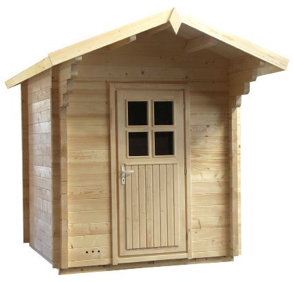
Montageanleitung

      DE
                     GARTENSAUNA COUNTRY

       Hinweise für die Baugenehmigung, Fundament,
          Verankerung, Anlieferung und Entladung

Baugenehmigung:

Erkundigen Sie sich unbedingt vor der Montage des Gartenhauses bei Ihrer zuständigen
Baubehörde (Gemeindeamt; Magistrat), ob eine Baugenehmigung erforderlich ist. Diese
brauchen Sie möglicherweise, da ab einem bestimmten Raumvolumen eine Genehmigung
erforderlich ist. Dies ist Ländersache und wird daher in jedem Bundesland unterschiedlich
gehandhabt.

Erkundigen Sie sich bei Ihrer zuständigen Baubehörde                     (Gemeindeamt;
Magistrat) bezüglich den Bauvorschriften und Belastungsnormen.

Betonfundament:

Ein solides Betonfundament ist wichtig für die Haltbarkeit sowie für die Sicherheit Ihres
Gartenhauses.
Wir empfehlen Ihnen das Fundament von einem Fachmann herstellen zu lassen.
Es ist die Basis für eine ordnungsgemäße Verankerung Ihres Gartenhauses. Nur so haben
Sie die Garantie bei der Montage und der Benutzung keine Probleme (z.B. Feuchtigkeit,
Stabilität) zu haben.

Es bestehen mehrere Möglichkeiten, wie Sie das Fundament für Ihr Gartenhaus ausführen
können.

04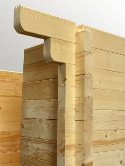
Die beiden folgenden haben sich in der Paxis aber am besten bewährt:

    •Fundamentplatte (Bodenplatte)

    •Streifenfundament

Dabei ist bei beiden Varianten ein absolut waagrechtes und tragfähiges Fundament
zu gewährleisten. Nur so kann eine einwandfreie Montage der einzelnen
Funktionsmodule mit einer exakten Passgenauigkeit gewährleistet werden.

Nach Fertigstellung und Austrocknung der Betonplatte empfehlen wir diese mit Dachpappe
oder Flämmpappe zu flämmen, um sie komplett abzudichten.

Fundamentplatte (Bodenplatte):

Eine Bodenplatte gewährleistet ein frostsicheres Fundament für das Gartenhaus. Beachten
Sie, dass in den Beton Baustahlgittermatten eingelegt (bewehrt) werden müssen, um eine
maximale Stabilität zu erreichen und die Platte vor Rissen zu schützen.

              Erde                              Beton 15 cm dick

                     Kies 15 cm dick                  PE-Folie

                                                                                   05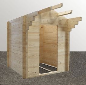
Montageanleitung

      DE
Streifenfundament:

Je nach statischen Erfordernissen bzw. örtlichen Gegebenheiten, können
Streifenfundamente unterschiedlich ausgeführt werden. Man unterscheidet zwei Arten
von Streifenfundamente:

     •Streifenfundament unbewehrt
     •Streifenfundament bewehrt

Damit ein frostsicheres Streifenfundament entsteht, muss mindestens 80 cm tief gegraben
werden. Auf den Fundamentstreifen liegen dann die tragenden Wände des Gartenhauses
auf.

Diese Bauweise hat die Vorteile, dass die Bodenplatte dünner sein kann und weniger
Bewehrung nötig ist.

                             Erde                     Beton 10 cm dick

                                                          PE-Folie
                     80 cm

                                            Kies 10 cm dick

                                    30 cm

Das Fundament sollte um ca. 10 bis 15 mm kleiner sein als Ihr Gartenhaus, damit das
Wasser an den Außenwänden des Hauses und an den Außenseiten des Fundamentes
abrinnen kann.

06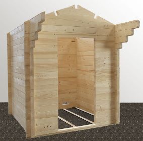
Hinweis:
Die Fundamente müssen absolut waagrecht sein um die Tragfähigkeit des Hauses
zu gewährleisten. Sollte die Fundamentplatte größer als die Grundfläche des
Gartenhauses sein, kann sich Regenwasser ringsum des Gartenhauses ansammeln.
Dadurch kann das Holz der Wandelemente ständig auf nassem Boden stehen. Als
Folge kann es passieren, dass das Holz das Wasser aufsaugt und zu faulen beginnt.
Wir weisen Sie darauf hin, dass wir für dadurch auftretende Schäden
keine Gewährleistung übernehmen.
Verankerung des Gartenhauses:
Es ist sehr wichtig, dass das Gartenhaus fest mit der Bodenplatte oder dem
Streifenfundament verankert wird. Bei starkem Wind können große Kräfte auf das
Gartenhaus einwirken. Um Schäden am eigenen oder fremden Eigentum zu vermeiden
ist eine fachgerechte Verankerung unbedingt notwendig.
Wir weisen Sie darauf hin, dass die Verankerung des Gartenhauses im
Verantwortungsbereich des Kunden liegt, und wir für auftretende Schäden keine
Gewährleistung übernehmen.
Holzschutz außen:
Das Holz der Gartensauna ist unbehandelt. Um die Lebensdauer Ihrer Gartensauna zu
erhöhen empfehlen wir sie außen mit einer geeigneten Holzschutzfarbe zu streichen.
Dacheindeckung:
Die im Lieferumfang enthaltene Dachpappe dient als Ersteindeckung. Wir empfehlen
zusätzlich das Dach mit Bitumenschindeln, Blech oder einer geeigneten Folie einzudecken.
Lieferung des Gartenhauses:
Das Gartenhaus wird per LKW (eventuell auch per Sattelzug) angeliefert. Dabei muss
gewährleistet sein, dass die Zufahrt zum Entladeort möglich ist.
Für die Entladung und Montage des Gartenhauses sind mind. zwei Personen nötig.
07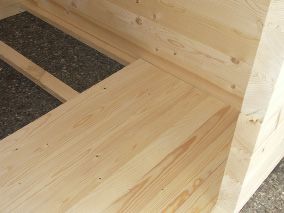
Montageanleitung

      DE
                                             Bodenrahmen für
                                             Außensauna
                                             Schrauben 4 x 60 mm

 Abb 1.1

           Schrauben 5 x 100 mm
                                   Abb 1.2

       1 Blockbohle 230 x 6,5 x 7 cm mit Ausnehmungen für Gewindestangen

                 Abb 1.3

           1 Blockbohle 230 x 6,5 x 7 cm mit Ausnehmungen für Gewindestangen
           und Türe
08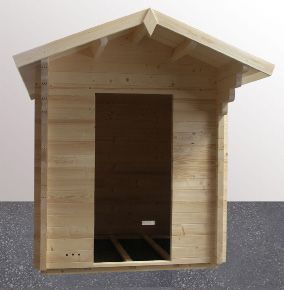
1 Blockbohle 230 x 14,6 x 7 cm mit Abluftausschnitt

Abb 1.4

1 Blockbohle 69 x 14,6 x 7 cm mit Bohrungen für Zuluft

Abb 1.5

                                                         09
Montageanleitung

     DE

     Abb 1.6

     Gewindestangen 8 mm

                                     15

                                     14

                                      13
                                      12

                                      11
                                      10
     Abb 1.7               Abb 1.8    09

10
Verschraubung oben - restl. Gewindestange
oberhalb der Schraubenmutter abschneiden
Abb 1.9
Abb 1.10
Verschraubung unten
Abb 1.11
11Montageanleitung
DE
Abb.1.12
Abluftschieber
4 Stk.Schrauben 3 x 40 mm
Abb 1.13
12Abb.1.21
Abb 1.14
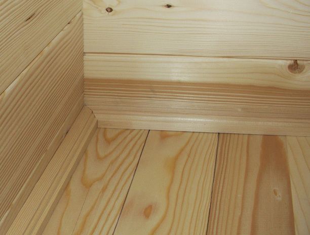
Fußboden - Schrauben 3,5 x 50 mm
Schrauben 5 x 100 mm
Abb 1.15
Sockelleisten - Schrauben 3,2 x 40 mm
13Montageanleitung
DE
Schrauben 4 x 70 mm
Messen Sie vom
Fußboden bis Unterkante
Dachauflageleiste 206 cm.
206 cm
Abb 1.16
Abb 1.17
14Abb 1.18
Dachelemente von oben mit Auflageleisten verschrauben Schrauben 5 x 80 mm
Abb.1.19
15Montageanleitung
DE
Schrauben 5 x 70 mm
87 cm
41 cm
Abb 1.20
Abb 1.21
16Schrauben 3,5 x 50 mm
Banksichtblende
- Ansicht von hinten
Abb 1.22
Banksichtblende
Abb 1.23
17Montageanleitung
DE
Schrauben 3,5 x 50 mm
25 cm
Abb 1.24
4 Stk. Schrauben 3 x 40 mm
Abb 1.25 Abb 1.26 Abb 1.27
18Legen Sie zuerst die Montageleisten
der Türe und die Schrauben in die
Kabine.
Stellen Sie dann das Türelement in die
Türöffnung, nehmen die obere Mon-
tageleiste (1), teilen diese links und
rechts gleichmäßig auf und verschrau-
ben die Leiste mit der Türe.
Als nächstes verschrauben Sie die
seitlichen Montageleisten. (2). Zum
Schluss wird die untere Leiste ver-
schraubt.
Schrauben 3 x 40 mm
Abb 1.33
1.
2.
Abb 1.34
19Montageanleitung
DE
Schrauben 3 x 40 mm
Abb 1.35
Abb 1.36
20Schrauben 3,5 x 50 mm
2 cm
Abb 1.28
Abb 1.29
Windbrett seitlich Schrauben 3,5 x 50 mm
Abb 1.30
Schrauben 3,5 x 50 mm
Abb 1.31
21Montageanleitung
DE
Schrauben
3,5 x 50 mm
Abb 1.31
Windbretter seitlich
Abb 1.32
22Abb 1.37
Verlegen Sie zwei Reihen Dachpappe pro Wandseite mit Überstand und
befestigen sie mit Dachpappnägel. Zum Abschluss legen Sie zusätzlich eine
Bahn Dachpappe über den Giebel und befestigen sie wieder mit Dachpapp-
nägel..
Abb 1.38
23GRUNDRISS COUNTRY 319 x 264 x 290 cm 24
sentiotec GmbH | Division of Harvia Group | Oberregauer Straße 48, A-4844 Regau
 T +43 (0) 7672/277 20-567 | F -801 | info@sentiotec.com | www.sentiotec.com
Assembly Instruction

 DE
 EN
 FR
 FI

Garden sauna      COUNTRY
                   319 x 264 x 290 cm

Version 10/17                     ID no. 1-030-307
Assembly instructions
EN
Garden sauna
COUNTRY
E xterior dimension:
319 x 264 x 290 cm
Interior dimension:
200 x 200 x 210 cm
Wall thickness:
70 mm
Dear customer,
Before you begin with the work, check that all the individual parts have been delivered against the parts list.
If you discover any missing parts, notify your dealer within 14 days of receiving the sauna cabin.
Keep the delivery note, the invoice and the assembly instructions in
a safe place in case of any questions.
You require the following tools:
1 hammer with a wooden head or a rubber hammer
1 cordless screwdriver with bits for cross-head screws and Torx
1 roller tape measure
1 drill bit Ø10 mm; 1 drill bit Ø3 mm
1 spirit level
1 pencil
You need an assistant for the assembly. We also advise you to pre-drill
the holes for the screws.
! The electrical connection may only be performed by a qualified electrician or similarly
qualified person.
There may be slight deviations in the dimensions.
Subject to technical modifications and misprints.
02COUNTRY parts list
Front face with doors floor frames 206 x 8 x 4 cm
3
2 floor frames 206 x 12 x 4 cm
block plank 230 x 6.5 x 7 cm with recess for
1 22 floor boards 199.5 x 9.5 x 1.9 cm
door frame and 4 recesses for threaded rods 4 skirting boards 200 x 2.5 x 2.5 cm
13 block planks 69 x 14.6 x 7 cm with electrical 70 roof boards 142 x 9.5 x 1.8 cm
installation drill holes 2 weather boards 319 x 4 x 2 cm
1 block plank 69 x 14.6 x 7 cm with electrical 4 weather boards 145.5 x 12.5 x 1.9 cm
installation drill holes and 3 drill holes for supply air 5 bench support slats 4 x 4 cm (2 pcs. 58 cm;
14 block planks 69 x 14.6 x 7 cm 2 pcs. 116 cm; 1 pc. 48 cm)
2 block planks 230 x 14.6 x 7 cm over door frame 1 bench 137.5 x 62 cm
with 4 recesses for threaded rods 2 benches 199 x 62 cm
1 roof 230 x 48.5 x 7 cm 2 back rests
2 interior door panels 86 x 5.5 x 2 cm 2 head rests
2 interior door panels 201 x 5.5 x 2 cm 1 bench screen 199 cm
1 door frame 198 x 90 cm
Right and left sides 1 interior light
1 light screen
6 block planks 230 x 14.6 x 7 cm
2 1 floor grid 70 x 50 cm
2 block planks 252.5 x 14.6 x 7 cm 1 heater safety guard, 2 parts
2 block planks 275 x 14.6 x 7 cm 1 ventilation shutter
2 block planks 297.5 x 14.6 x 7 cm 1 assembly material set
2 block planks 319 x 17 x 7 cm 1 assembly instruction manual
6 threaded rods 8 mm incl. nuts
Rear face 3 silicon cables 5-pin 5 x 1.5 mm²
20 m² roofing felt
block plank 230 x 6.5 x 7 cm with 2 recesses
1 1 insect screen
for threaded rods
1 block plank 230 x 14.6 x 7 cm
with ventilation recess
15 block planks 230 x 14.6 x 7 cm
with 2 drill holes
1 roof 230 x 48.5 x 7 cm
3 block planks for roof 319 x 13.6 x 7 cm
2 roof support slats 200 x 4 x 4 cm
2 roof support slats 192 x 4 x 4 cm
2 roof elements 199 x 99 x 6.5 cm
2 floor frames 214 x 8 x 4 cm
The parts list can also be used as a claims sheet.
03Assembly instructions
EN
GARDEN SAUNA COUNTRY
Notes for the planning permission, foundation,
anchorage, delivery and unloading
Planning permission
Before installing the garden sauna, make sure you enquire about whether planning
permission is required at your local planning authority (municipal office, magistrate).
You may need this as permission is required above a certain room volume. This depends
on where you live exactly and is therefore handled differently from country to country.
Check with your local planning authority (municipal office, magistrate)
with respect to the building regulations and load standards.
Concrete foundation:
A solid concrete foundation is important for the durability as well as the safety of your
garden sauna.
We recommend having the foundation laid by a specialist.
It is the basis for a proper anchorage of your garden sauna. Only then can you ensure
that there will be no difficulties with assembly and use.
There are several ways that you can lay the foundation for your garden sauna.
04However, the two options below have proven to be the best in practice:
• Foundation slab (base plate)
• Strip foundation
For both types, a foundation that is absolutely flat and load-bearing must be ensured.
Only then can the assembly of the individual modules be ensured without any difficulties
and with a precise fit.
Once the concrete slab has been completed and dried out, we recommend torching it
with roofing felt or torch-on felt in order to seal it completely.
Foundation slab (base plate)
A base plate ensures a frost-proof foundation for the garden sauna. Note that structural
steel mesh mats must be laid in the concrete (reinforced) in order to achieve maximum
stability and protect the slab from cracking.
Ground Concrete 15 cm thick
Gravel 15 cm thick PE-film
05Assembly instructions
EN
Strip foundation
Depending on the structural requirements and local conditions, strip foundations can be
laid in different ways. There are two types of strip foundations:
• strip foundation - not reinforced
• strip foundation - reinforced
To make a frost-proof strip foundation, you must dig at least 80 cm deep into the ground.
The supporting walls of the garden sauna are then laid on the foundation strips.
This construction has the advantage that the base plate can be thinner and less
reinforcement is necessary.
Ground Concrete 10 cm thick
PE-film
80 cm
Gravel 10 cm thick
30 cm
The foundation should be about 10 to 15 mm smaller than your garden sauna so that
water can run off the outer walls of the sauna and the outer sides of the foundation.
06Note:
The foundations must be absolutely flat to ensure the load-bearing capacity of the sauna.
If the foundation slab is larger than the floor space of the garden sauna, rainwater can start
to collect around the sauna This means that the wooden wall elements would be constantly
standing on wet ground. This could result in the wood absorbing the water and starting to rot.
We point out that we do not accept any liability for the resulting damage.
Anchoring the garden sauna:
It is essential that the garden sauna is firmly anchored on the base plate or the strip
foundation. Strong winds can exert a powerful force on the garden sauna. To prevent
damage to your property or third-party property, proper anchoring is essential.
We point out that anchoring the garden sauna is the responsibility of the customer and we
do not accept any liability for accidental damage.
Wood protection outside:
The wood of the garden sauna is untreated. If you want to increase the life of your garden
sauna, we recommend painting with a suitable protective painting.
Roofing:
The included roofing felt serves as an initial cover. We also recommend to cover the roof
with bitumen shingles, sheet metal or a suitable foil.
Delivery of the garden sauna:
The garden sauna is delivered by lorry (also possible by semi-trailer truck).
Access to the unloading area must be ensured.
At least two people are required for unloading and installing the garden sauna.
07Assembly instructions
EN
Base frame for
outer sauna
Screws 4 x 60 mm
Fig. 1.1
Screws 5 x 100 mm
Fig. 1.2
1 block plank 230 x 6.5 x 7 cm with recesses for threaded rods
Fig. 1.3
1 block plank 230 x 6.5 x 7 cm with recesses for threaded rods and doors
081 block plank 230 x 14.6 x 7 cm with ventilation recess
Fig. 1.4
1 block plank 69 x 14.6 x 7 cm with drill holes for supply air
Fig. 1.5
09Assembly instructions
EN
Fig. 1.6
Threaded rods 8 mm
15
14
13
12
11
10
Fig. 1.7 Fig. 1.8 09
10Screw joints at top – cut off the remaining
threaded rod above the nut
Fig. 1.9
Fig. 1.10
Screw joints at bottom
Fig. 1.11
11Assembly instructions
EN
Fig.1.12
Ventilation shutter
4 screws 3 x 40 mm
Fig. 1.13
12Fig.1.21
Fig. 1.14
Floor - screws 3.5 x 50 mm
Screws 5 x 100 mm
Fig. 1.15
Skirting board - screws 3.2 x 40 mm
13Assembly instructions
EN
Screws 4 x 70 mm
Measure from floor to
the bottom edge of the
roof support slat 206 cm.
206 cm
Fig. 1.16
Fig. 1.17
14Fig. 1.18
Screw the roof elements from above with the support slats Screws x 80 mm
Fig. 1.19
15Assembly instructions
EN
Screws 5 x 70 mm
87 cm
41 cm
Fig. 1.20
Fig. 1.21
16Screws 3.5 x 50 mm
Bench screen
- view from rear
Fig. 1.22
Bench screen
Fig. 1.23
17Assembly instructions
EN
Screws 3.5 x 50 mm
25 cm
Fig. 1.24
4 screws 3 x 40 mm
Fig. 1.25 Fig. 1.26 Fig. 1.27
18First put the mounting slats of
the door and the screws in the cabin.
Then place the door element in the
doorway, take the top slat (1), place
it so that left and right is the same
and screw the slat to the door.
Next, screw on the side mounting
slats. (2). Finally, screw on the
bottom slat.
Screws 3 x 40 mm
Fig. 1.33
1.
2.
Fig. 1.34
19Assembly instructions
EN
Screws 3 x 40 mm
Fig. 1.35
Fig. 1.36
20Screws 3.5 x 50 mm
2 cm
Fig. 1.28
Fig. 1.29
Wind board, side, screws 3.5 x 50 mm
Fig. 1.30
Screws 3.5 x 50 mm
Fig. 1.31
21Assembly instructions
EN
Screws
3.5 x 50 mm
Fig. 1.31
Weather boards, side
Fig. 1.32
22Fig. 1.37
Place the two rows of roofing felt for each wall side with overhang and
fasten it with roofing felt nails. Finally, place another row of roofing felt
over the weather board and fasten it again with roofing felt nails.
Fig. 1.38
23COUNTRY FLOOR PLAN 319 x 264 x 290 cm 24
sentiotec GmbH | Division of Harvia Group | Oberregauer Straße 48, A-4844 Regau
 T +43 (0) 7672/277 20-567 | F -801 | info@sentiotec.com | www.sentiotec.com
Instructions de montage
Assembly instructions

   DE
   EN
   FR
   FI

Sauna de jardin         COUNTRY
                        319 x 264 x 290 cm

Version 10/17                        N° d´ident. 1-030-307
Instructions de montage
FR
Sauna de jardin
COUNTRY
imensions extérieures : 319 x 264 x 290 cm
D
Dimensions intérieures : 200 x 200 x 210 cm
Épaisseur des parois : 70 mm
Cher client,
Avant de commencer les travaux, vérifiez au moyen de la nomenclature si toutes les pièces ont bien été livrées.
S’il devait s’avérer que des pièces manquent, informez votre revendeur dans les 14 jours suivant la réception de la
cabine.
Conservez le bon de livraison, la facture et les instructions de montage dans un endroit sûr pour
vous y reporter en cas de question éventuelle.
Vous avez besoin des outils suivants :
1 marteau avec des cales ou un maillet en caoutchouc
1 visseuse électrique avec embouts pour vis Phillips et Torx
1 ruban de mesure
1 perceuse de Ø 10 mm ; 1 perceuse de Ø 3 mm
1 niveau à bulle
1 crayon à papier
Une deuxième personne doit être disponible pour vous aider. En outre,
nous recommandons de prépercer les trous pour les vis.
! Seul un électricien spécialisé ou une personne ayant une qualification similaire est habilité
à procéder au raccordement électrique.
Des écarts mineurs dans les dimensions sont possibles.
Sous réserve d’erreurs techniques et de fautes d’impression.
02Nomenclature COUNTRY
Face avant avec porte cadres de plancher 206 x 12 x 4 cm
2
22 planches de plancher 199,5 x 9,5 x 1,9 cm
1 madrier 230 x 6,5 x 7 cm avec évidement pour 4 plinthes 200 x 2,5 x 2,5 cm
cadre de porte et 4 découpes pour tiges filetées 70 planches de toiture 142 x 9,5 x 1,8 cm
13 madriers 69 x 14,6 x 7 cm avec alésages pour 2 poutrelles de toiture 319 x 4 x 2 cm
installation électrique 4 poutrelles de toiture 145,5 x 12,5 x 1,9 cm
1 madrier 69 x 14,6 x 7 cm avec alésages pour instal- 5 baguettes d’appui de banc 4 x 4 cm
lation électrique et 3 alésages pour arrivée d’air (2 pièces de 58 cm ; 2 pièces de 116 cm ;
14 madriers 69 x 14,6 x 7 cm 1 pièce de 48 cm)
2 madriers 230 x 14,6 x 7 cm pour dessus de cadre de 1 banc 137,5 x 62 cm
porte avec 4 découpes pour tiges filetées 2 bancs 199 x 62 cm
1 toiture 230 x 48,5 x 7 cm 2 dossiers
2 habillages de porte, intérieur 86 x 5,5 x 2 cm 2 appuie-têtes
2 habillages de porte, intérieur 201 x 5,5 x 2 cm 1 écran de banc 199 cm
1 cadre de porte 198 x 90 cm
Côtés droit et gauche 1 éclairage intérieur
1 abat-jour pour lampe
6 madriers 230 x 14,6 x 7 cm
2 1 grille de plancher 70 x 50 cm
2 madriers 252,5 x 14,6 x 7 cm 1 grille de protection de poêle en 2 parties
2 madriers 275 x 14,6 x 7 cm 1 registre d’aération
2 madriers 297,5 x 14,6 x 7 cm 1 kit de matériel de montage
2 madriers 319 x 17 x 7 cm 1 exemplaire des Instructions de montage
6 tiges filetées 8 mm, écrous inclus
Face arrière 3 m de câble silicone à 5 pôles, 5 x 1,5 mm²
20 m² de carton bitumé
1 madrier 230 x 6,5 x 7 cm avec 2 découpes 1 moustiquaire
pour tiges filetées
1 madrier 230 x 14,6 x 7 cm
avec découpe d’aération
15 madriers 230 x 14,6 x 7 cm avec
2 alésages
1 toiture 230 x 48,5 x 7 cm
3 madriers pour toiture 319 x 13,6 x 7 cm
2 baguettes d’appui de toit 200 x 4 x 4 cm
2 baguettes d’appui de toit 192 x 4 x 4 cm
2 éléments de toiture 199 x 99 x 6,5 cm
2 cadres de plancher 214 x 8 x 4 cm
3 cadres de plancher 206 x 8 x 4 cm
La nomenclature sert également de formulaire de réclamation !
03Instructions de montage
FR
SAUNA DE JARDIN COUNTRY
Informations concernant le permis de construire, les
fondations, l’ancrage, la livraison et le déchargement
Permis de construire :
Avant d’installer la maisonnette de jardin, renseignez-vous impérativement auprès de votre
autorité locale de construction (mairie ; magistrat) pour savoir si un permis de construire est
requis. Vous pouvez en avoir besoin parce qu’un permis est nécessaire à partir d’un certain
volume de pièce. Il s’agit d’une question qui relève des États fédéraux et qui est donc traitée
différemment d’un État fédéral à l’autre.
Renseignez-vous auprès de votre autorité compétente en matière de construction (mairie,
magistrat) sur les règles de construction et les normes de charge.
Fondations en béton :
Des fondations solides en béton sont importantes pour la durabilité et la sécurité de votre
maisonnette de jardin.
Nous vous recommandons de faire construire les fondations par un spécialiste.
C’est la base d’un bon ancrage de votre maisonnette de jardin. C’est le seul moyen de
garantir que vous n’aurez pas de problèmes (p. ex. humidité, stabilité) pendant le montage
et l’utilisation de votre sauna.
Il y a plusieurs façons de construire les fondations de votre maisonnette de jardin.
Toutefois, les deux suivantes se sont avérées être les meilleures dans la pratique :
04• Plaque de fondation (dalle)
• Semelle filante (fondation en bandes)
Dans les deux variantes, une fondation absolument horizontale et porteuse doit être garan-
tie. C’est la seule façon d’assurer un montage parfait des différents modules fonctionnels et
de garantir qu’ils s’adaptent exactement.
Après l’achèvement et le séchage de la dalle de béton, nous recommandons de l’enduire de
carton bitumé ou de feutre d’entoilage afin de l’étanchéifier complètement.
Plaque de fondation (dalle) :
Avec une dalle, la fondation de la maisonnette de jardin résistera au gel. Notez que des
grilles d’armature doivent être placées dans le béton pour obtenir une stabilité maximale et
protéger la dalle contre la fissuration.
Terre Béton épaisseur 15 cm
Gravier épaisseur 15 cm Film PE
05Instructions de montage
FR
Semelle filante (fondation en bandes) :
Selon les exigences statiques et les conditions locales, les fondations en bandes peuvent être
construites de différentes manières. On distingue deux types de fondations en bandes :
• Semelle filante sans armure
• Semelle filante avec armure
Afin que les fondations en bandes résistent au gel, il faut creuser sur au moins 80 cm de
profondeur. Les murs porteurs de la remise de jardin reposent ensuite sur les bandes des
fondations.
Cette méthode de construction présente l’avantage que la dalle peut être plus mince et
nécessite moins de renfort.
Terre Béton épaisseur 10 cm
Film PE
80 cm
Gravier épaisseur
10 cm
30 cm
Les fondations doivent être d’environ 10 à 15 mm plus petites que votre maisonnette
de jardin afin que l’eau puisse s’écouler sur les murs extérieurs de la maisonnette et sur
l’extérieur de la fondation.
06Remarque :
Les fondations doivent être absolument horizontales pour pouvoir porter la charge
de la maisonnette. Si la dalle de fondation est plus grande que la surface au sol de la
maisonnette de jardin, l’eau de pluie peut s’accumuler autour de la remise. De ce fait,
le bois des éléments muraux risquerait de reposer en permanence sur un sol humide.
En conséquence, il pourrait arriver que le bois absorbe l’eau et commence à pourrir.
Nous attirons votre attention sur le fait que nous déclinons toute responsabilité pour les
dommages qui en résulteraient.
Ancrage de la maisonnette de jardin :
Il est très important que la maisonnette de jardin soit solidement ancrée à la dalle ou à
la fondation en bandes. Par vent fort, de grandes forces peuvent agir sur la maisonnette
de jardin. Afin d’éviter d’endommager votre propriété ou les biens de tiers, un ancrage
professionnel est absolument nécessaire.
Nous attirons votre attention sur le fait que l’ancrage de la maisonnette de jardin est à
la charge du client et que nous déclinons toute responsabilité pour les dommages qui
pourraient survenir.
Protection du bois à l’extérieur :
Le bois du sauna de jardin n’est pas traité. Afin de prolonger la durée de vie de votre sauna
de jardin, nous vous recommandons de le peindre avec une peinture de protection du bois
appropriée à l’extérieur.
Couverture de la toiture :
Le carton bitumé inclus dans la livraison sert de revêtement initial. Nous recommandons de
recouvrir en outre la toiture de bardeaux de bitume, de tôle ou d’un film approprié.
Livraison de la maisonnette de jardin :
La maisonnette de jardin est livrée par camion (éventuellement aussi par camion et
remorque). Il faut donc veiller à ce que l’accès au site de déchargement soit possible.
Au moins deux personnes sont nécessaires pour décharger et monter la maisonnette de
jardin.
07Instructions de montage
FR
Cadre de plancher
pour sauna extérieur
Vis 4 x 60 mm
Fig 1.1
Vis 5 x 100 mm
Fig 1.2
1 madrier 230 x 6,5 x 7 cm avec découpe pour tiges filetées
Fig 1.3
1 madrier 230 x 6,5 x 7 cm avec découpe pour tiges filetées et portes
081 madrier 230 x 14,6 x 7 cm avec découpe d’aération
Fig 1.4
1 madrier 69 x 14,6 x 7 cm avec alésages pour arrivée d’air
Fig 1.5
09Instructions de montage
FR
Fig 1.6
Tiges filetées 8 mm
15
14
13
12
11
10
Fig 1.7 Fig 1.8 09
10Vissage en haut - Couper la tige filetée
restante au-dessus de l’écrou
Fig 1.9
Fig 1.10
Vissage en bas
Fig 1.11
11Instructions de montage
FR
Fig 1.12
Registre d’aération
4 vis 3 x 40 mm
Fig 1.13
12Fig 1.21
Fig 1.14
Plancher - Vis 3,5 x 50 mm
Schrauben 5 x 100 mm
Fig 1.15
Plinthes - Vis 3,2 x 40 mm
13Instructions de montage
FR
Vis 4 x 70 mm
Mesurez
206 cm à partir du sol
jusqu’au bord inférieur
de la baguette d’appui
de toiture.
206 cm
Fig 1.16
Fig 1.17
14Fig 1.18
Vissez les éléments de toiture sur les baguettes d’appui en procédant par le haut
Vis 5 x 80 mm
Fig 1.19
15Instructions de montage
FR
Vis 5 x 70 mm
87 cm
41 cm
Fig 1.20
Fig 1.21
16Vis 3,5 x 50 mm
Écran de banc
- Vue de l’arrière
Fig 1.22
Écran de banc
Fig 1.23
17Instructions de montage
FR
Vis 3,5 x 50 mm
25 cm
Fig 1.24
4 vis 3 x 40 mm
Fig 1.25 Fig 1.26 Fig 1.27
18Placez d’abord les barres de montage
des portes et les vis dans la cabine.
Placez alors l’élément de porte dans
l’ouverture, prenez la barre de mon-
tage supérieure (1), divisez-la unifor-
mément à gauche et à droite et vissez
la barre à la porte.
Vissez ensuite les barres de montage
latérales. (2). Pour finir, vissez la barre
inférieure.
Vis 3 x 40 mm
Fig 1.33
1.
2.
Fig 1.34
19Instructions de montage
FR
Vis 3 x 40 mm
Fig 1.35
Fig 1.36
20Vis 3,5 x 50 mm
2 cm
Fig 1.28
Fig 1.29
Bordure de pignon latérale Vis 3,5 x 50 mm
Fig 1.30
Vis 3,5 x 50 mm
Fig 1.31
21Instructions de montage
FR
Vis
3,5 x 50 mm
Fig 1.31
Bordures de pignon latérales
Fig 1.32
22Fig 1.37
Posez deux rangées de carton bitumé par côté de mur en porte-à-faux et
fixez-le avec des clous prévus à cet effet. Pour finir, placez une feuille de car-
ton bitumé sur le pignon et fixez-la de nouveau avec des clous prévus à cet
effet.
Fig 1.38
23PLAN COUNTRY 319 x 264 x 290 cm 24
sentiotec GmbH | Division of Harvia Group | Oberregauer Straße 48, A-4844 Regau
 T +43 (0) 7672/277 20-567 | F -801 | info@sentiotec.com | www.sentiotec.com
Asennusohje
Assembly instructions

   DE
   EN
   FR
   FI

Pihasauna               COUNTRY
                        319 x 264 x 290 cm

Versio 10/17                        Tunnistenro 1-030-307
Asennusohje
FI
Pihasauna
COUNTRY
Ulkomitta: 319 x 264 x 290 cm
Sisämitta: 200 x 200 x 210 cm
Seinän paksuus: 70 mm
Hyvä asiakkaamme,
Ennen töiden aloittamista tarkista osaluettelon mukaisesti, että kaikki yksittäiset osat ovat lähetyksessä mukana.
Jos jokin osa puuttuu, ota kahden viikon aikana yhteyttä saunan toimittajaan.
Säilytä lähetyslista, lasku ja asennusohje myöhempää käyttöä varten.
Tarvitset seuraavia työkaluja:
1 vasara ja puupalikka tai kumivasara
1 akkuporakone ristipääruuvi- ja torx-kärjillä
1 rullamitta
1 poranterä Ø10 mm; 1 poranterä Ø3 mm
1 vesivaaka
1 lyijykynä
Asennukseen tarvitaan kaksi henkilöä! Suosittelemme ruuvien reikien poraamista etukäteen.
! Vain sähköalan ammattilainen tai vastaavan pätevyyden omaava henkilö saa
suorittaa sähköliitännät.
Pienet mittavaihtelut ovat mahdollisia.
Oikeus teknisiin muutoksiin ja painovirheisiin pidätetään.
02Osaluettelo COUNTRY
Etupuoli ovella 0 kattolautaa 142 x 9,5 x 1,8 cm
7
2 otsalautaa 319 x 4 x 2 cm
1 hirsi 230 x 6,5 x 7 cm, upotus oven kehykselle ja 4 4 otsalautaa 145,5 x 12,5 x 1,9 cm
jyrsintää kierretangoille 5 lauteenkannatinlistaa 4 x 4 cm (2 kpl 58 cm;
13 hirttä 69 x 14,6 x 7 cm, sähköasennusrei’illä 2 kpl 116 cm; 1 kpl 48 cm)
1 hirsi 69 x 14,6 x 7 cm, sähköasennusrei’illä ja 3 kor- 1 laude 137,5 x 62 cm
vausilmareiällä 2 penkkiä 199 x 62 cm
14 hirttä 69 x 14,6 x 7 cm 2 selkänojaa
2 hirttä 230 x 14,6 x 7 cm, oven kehyksen päälle ja 4 2 päätukea
jyrsintää kierretangoille 1 laudepaneeli 199 cm
1 katto 230 x 48,5 x 7 cm 1 ovikehys 198 x 90 cm
2 ovilistaa sisälle 86 x 5,5 x 2 cm 1 sisävalo
2 ovilistaa sisälle 201 x 5,5 x 2 cm 1 lampunvarjostin
1 lattiaritilä 70 x 50 cm
Oikea ja vasen sivu 1 kiuassuojaritilä 2-os.
1 tuuletusluukku
6 hirttä 230 x 14,6 x 7 cm
2 1 asennusmateriaalisarja
2 hirttä 252,5 x 14,6 x 7 cm 1 asennusohje
2 hirttä 275 x 14,6 x 7 cm 6 kierretankoa 8 mm ml. mutterit
2 hirttä 297,5 x 14,6 x 7 cm 3 m silikonijohtoa, 5-napainen 5 x 1,5 mm²
2 hirttä 319 x 17 x 7 cm 20 m² kattohuopaa
1 hyönteissuojaritilä
Takaosa
hirsipalkki 230 x 6,5 x 7 cm,
1
2 jyrsintää kierretangoille
1 hirsipalkki 230 x 14,6 x 7 cm, tuuletusaukolla
15 hirttä 230 x 14,6 x 7 cm, 2 reiällä
1 katto 230 x 48,5 x 7 cm
3 hirttä kattoon 319 x 13,6 x 7 cm
2 katon reunalistaa 200 x 4 x 4 cm
2 katon reunalistaa 192 x 4 x 4 cm
2 kattoelementtiä 199 x 99 x 6,5 cm
2 lattiakehystä 214 x 8 x 4 cm
3 lattiakehystä 206 x 8 x 4 cm
2 lattiakehystä 206 x 12 x 4 cm
22 lattialautaa 199,5 x 9,5 x 1,9 cm
4 jalkalistaa 200 x 2,5 x 2,5 cm
Osaluettelo toimii myös reklamaatiolomakkeena!
03Asennusohje
FI
PIHASAUNA COUNTRY
Rakennuslupaa, perustuksia, kiinnitystä,
toimitusta ja kuorman purkamista koskevia ohjeita
Rakennuslupa:
Ota ehdottomasti ennen piharakennuksen pystyttämistä vastaavaan rakennusviranomaiseen
(kunnanvirasto; maistraatti) ja selvitä, tarvitsetko rakennus- tai toimenpideluvan. Saatat
tarvita sen, koska rakennuslupaa edellytetään tietystä koosta alkaen.
Ota yhteyttä vastaavaan rakennusviranomaiseen (kunnanvirasto; maistraatti) rakennusmääräyk-
siä ja kuormitusstandardeja koskevissa asioissa.
Betoniperustus:
Luja betoniperustus on piharakennuksesi kestävyyden ja turvallisuuden kannalta tärkeässä
roolissa.
Suosittelemme, että annat perustusten luomisen ammattilaisen tehtäväksi.
Se toimii piharakennuksesi asianmukaisen kiinnityksen perustana. Vain näin saat takuun
siitä, että asennuksen ja käytön yhteydessä ei ilmene ongelmia (esim. kosteus, tukevuus).
Piharakennuksesi perustukset voidaan tehdä usealla eri tavalla.
04Seuraavat kaksi ovat osoittautuneet käytännössä parhaiksi:
• Perustuslaatta (pohjalaatta)
• Sokkeliperustus
Kummassakin muunnelmassa on luotava ehdottoman vaakasuora ja kantava perustus.
Vain näin voidaan taata, että yksittäiset moduulit voidaan asentaa moitteettomasti ja
täsmälleen toisiinsa yhteensopivasti.
Suosittelemme, että betonilaatan valmiiksi saamisen ja kuivumisen jälkeen se eristetään
täysin tiiviiksi kattohuovalla tai alushuovalla.
Perustuslaatta (pohjalaatta):
Pohjalaatta takaa, että piharakennuksesi perustus kestää pakkasen. Huomaa, että
betoniin pitää maksimitukevuuden saavuttamiseksi ja laatan suojaamiseksi halkeamilta
laittaa valun yhteydessä raudoitusverkkoja (raudoitus).
Maa 15 cm paksu betoni
5 cm paksu sorakerros PC-kalvo
05Asennusohje
FI
Sokkeliperustus:
Sokkeliperustus voidaan toteuttaa eri tavoin staattisia vaatimuksia ja paikallisia oloja
vastaavasti. Olemassa on kaksi perussokkelityyppiä:
• Raudoittamaton sokkeliperustus
• Raudoitettu sokkeliperustus
Jotta sokkeliperustus kestäisi pakkasta, sen täytyy yltää vähintään 80 cm:n syvyyteen.
Piharakennuksen kantavat seinät ovat tällöin sokkelin varassa.
Tämän rakennustavan etuna on se, että pohjalaatta voi olla ohuempi ja raudoitusta tarvitaan
vähemmän.
Perustuksen tulisi olla n. 10 – 15 mm pienempi kuin piharakennuksesi, jotta rakennuksen
ulkoseinillä ja sokkelin ulkopuolella oleva vesi pääsee valumaan pois.
06Huomautus:
Rakennuksen kantavuuden takaamiseksi perustuksen täytyy olla ehdottoman vaakasuor-
assa. Jos perustuslaatta on suurempi kuin piharakennus, sadevettä pääsee kertymään pi-
harakennuksen ympärille. Näin seinäelementtien puu seisoo jatkuvasti märällä alustalla. Sen
seurauksena puu voi imeä vettä ja alkaa lahota.
Huomaathan, että tuotevastuumme ei kata tästä johtuvia vahinkoja.
Piharakennuksen kiinnittäminen:
On erittäin tärkeää, että piharakennus kiinnitetään lujasti pohjalaattaan tai sokkeliperustuk-
seen. Voimakkaalla tuulella piharakennus voi olla alttiina suurille voimille. Riittävä ankku
rointi on ehdottoman välttämätön omaa tai vieraan omaisuutta koskevien vahinkojen vält-
tämiseksi.
Huomaathan, että piharakennuksen kiinnitys kuuluu asiakkaan vastuualueeseen eikä tuote-
vastuumme kata sen takia ilmeneviä vahinkoja.
Puun suojakäsittely:
Pihasaunan puumateriaalia ei ole käsitelty. Jos haluat parantaa pihasaunasi säänkestoa, suo-
sittelemme sen maalaamista soveltuvalla suojamaalilla.
Vesikate:
Mukana toimitettava kattohuopa toimii alustavana katteena. Suosittelemme katon pinnoit-
tamista lisäksi bitumihuopakatteella tai kattopellillä.
Piharakennuksen toimitus:
Piharakennus toimitetaan kuorma-autolla (mahdollisesti rekalla). Tämän takia kuorman
purkupaikkaan täytyy päästä ajamaan raskaalla kalustolla.
Piharakennuksen purkamiseen kuormasta ja sen asentamiseen tarvitaan vähintään kaksi
henkilöä.
07Asennusohje
FI
Lattiakehys
ulkosauna
Ruuvit 4 x 60 mm
Kuva 1.1
Ruuvit 5 x 100 mm
Kuva 1.2
1 hirsi 230 x 6,5 x 7 cm, kolot kierretangoille
Kuva 1.3
1 hirsi 230 x 6,5 x 7 cm, kolot kierretangoille ja oville
081 hirsi 230 x 14,6 x 7 cm tuuletusaukolla
Kuva 1.4
1 hirsi 69 x 14,6 x 7 cm korvausilmarei’illä
Kuva 1.5
09Asennusohje
FI
Kuva 1.6
Kierretangot 8 mm
15
14
13
12
11
10
Kuva 1.7 Kuva 1.8 09
10Ruuvikiinnitys ylhäällä - katkaise ylimääräi-
nen kierretanko pois mutterin yläpuolelta
Kuva 1.9
Kuva 1.10
Alaruuviliitos
Kuva 1.11
11Asennusohje
FI
Kuva 1.12
Poistoilmaluukku
4 kpl. ruuveja 3 x 40 mm
Kuva 1.13
12Kuva 1.14
Lattia - ruuvit 3,5 x 50 mm
Ruuvit 5 x 100 mm
Kuva 1.15
Jalkalistat - ruuvit 3,2 x 40 mm
13Asennusohje
FI
Ruuvit 4 x 70 mm
Mittaa
lattiasta katon reunalistan
alareunaan 206 cm.
206 cm
Kuva 1.16
Kuva 1.17
14Kuva 1.18
Ruuvaa kattoelementit ylhäältä reunalistoihin, ruuvit 5 x 80 mm
Kuva 1.19
15Asennusohje
FI
Ruuvit 5 x 70 mm
87 cm
41 cm
Kuva 1.20
Kuva 1.21
16Ruuvit 3,5 x 50 mm
Laudepaneeli
- Näkymä takaa
Kuva 1.22
Laudepaneeli
Kuva 1.23
17Asennusohje
FI
Ruuvit 3,5 x 50 mm
25 cm
Kuva 1.24
4 kpl. ruuveja 3 x 40 mm
Kuva 1.25 Kuva 1.26 Kuva 1.27
18Kiinnitä ensin oven asennuslistat
ruuveilla rakennukseen.
Laita sitten ovielementti oviaukkoon.
Ota ylempi reunalista (1), aseta se kes-
kelle ovea ja ruuvaa lista kiinni.
Ruuvaa seuraavaksi sivuttaiset asen-
nuslistat. (2). Ruuvaa lopuksi alempi
lista kiinni.
Ruuvit 3 x 40 mm
Kuva 1.33
1.
2.
Kuva 1.34
19Asennusohje
FI
Ruuvit 3 x 40 mm
Kuva 1.35
Kuva 1.36
20Ruuvit 3,5 x 50 mm
2 cm
Kuva 1.28
Kuva 1.29
Otsalaudat sivulle, ruuvit 3,5 x 50 mm
Kuva 1.30
Ruuvit 3,5 x 50 mm
Kuva 1.31
21Asennusohje
FI
Ruuvit
3,5 x 50 mm
Kuva 1.31
Otsalaudat sivuilla
Kuva 1.32
22Kuva 1.37
Laita kaksi vuotaa kattohuopaa per lape niin, että ne menevät reunoista yli ja
kiinnitä ne huopanauloilla. Laita lopuksi lisäksi yksi vuota kattohuopaa harjal-
le ja kiinnitä sekin huopanauloilla.
Kuva 1.38
23POHJAPIIRROS COUNTRY 319 x 264 x 290 cm 24
sentiotec GmbH | Division of Harvia Group | Oberregauer Straße 48, A-4844 Regau
 T +43 (0) 7672/277 20-567 | F -801 | info@sentiotec.com | www.sentiotec.com
Sie können auch lesen