M.blue THE BALANCED WAY OF LIFE INSPIRED BY YOU - Christoph Miethke GmbH & Co. KG
←
→
Transkription von Seiteninhalten
Wenn Ihr Browser die Seite nicht korrekt rendert, bitte, lesen Sie den Inhalt der Seite unten
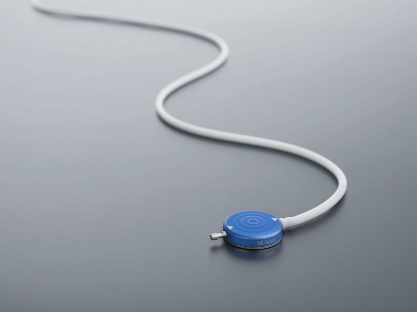
M.blue                       ®

      THE BALANCED WAY OF LIFE
      INSPIRED BY YOU

DE   Gebrauchsanweisung | GB Instructions for use | ES Instrucciones de manejo
FR   Mode d’emploi | IT Istruzioni per l‘uso | PT Instruções de utilização

       www.miethke.com

 US    This Instructions for Use is NOT intended for United State users. Please discard.
The Instructions for Use for United States users can be obtained by visiting our website at www.aesculapusa.com
and clicking the "Products" menu. If you wish to obtain a paper copy of the Instructions for Use, you may request
one by contacting your local Aesculap representative or Aesculap's customer service at 1-800-282-9000.
A paper copy will be provided to you upon request at no additional cost.
GEBRAUCHSANWEISUNG | DE
INHALTSVERZEICHNIS
INDIKATION 2
TECHNISCHE BESCHREIBUNG 2
ARBEITSWEISE DES VENTILS 2
AUSWAHL DER GEEIGNETEN DRUCKSTUFE 3
DRUCKSTUFENERKENNUNG IM RÖNTGENBILD 4
ANWENDUNG DER M.BLUE PLUS INSTRUMENTE 5
MÖGLICHE SHUNTKOMPONENTEN 9
SCHLAUCHSYSTEME 9
IMPLANTATION 9
VENTILPRÜFUNG 11
DRUCK-FLOW-CHARAKTERISTIK 11
VORSICHTSMAßNAHMEN UND KONTRAINDIKATIONEN 13
FUNKTIONSSICHERHEIT UND VERTRÄGLICHKEIT MIT
DIAGNOSTISCHEN VERFAHREN 13
NEBEN- UND WECHSELWIRKUNGEN 13
STERILISATION 13
FORDERUNGEN DER MDD (RL 93/42/EWG) 13
MEDIZINPRODUKTEBERATER 13
DIMENSIONEN 14
1DE | GEBRAUCHSANWEISUNG
Abb. 1: Querschnitt des M.blue
1. Verstellbare Differenzdruckeinheit 5. Differenzdruckeinheit
2. Saphirkugel 6. Saphirkugel
3. Tantalgewicht 7. Mikrospiralfeder
4. Rotor
INDIKATION Über einen Rotor (4) kann die Vorspan-
nung der mit dem Hebel verbundenen Stabfe-
Das M.blue dient zur Liquordrainage bei der
der durch die Haut verändert werden. Damit
Behandlung des Hydrocephalus.
kann der Einfluss des Tantalgewichts auf die
TECHNISCHE BESCHREIBUNG Saphirkugel beeinflusst und somit der Ven-
tilöffnungsdruck verstellt werden. Im distalen
Das M.blue ist ein aus Titan gefertigtes Ven- Teil des Ventils steuert eine Mikrospiralfeder
til. Es besteht aus einer verstellbaren Gravi- (7) den Öffnungsdruck der Differenzdruckein-
tationseinheit und einer Differenzdruckeinheit heit (5). Eine Saphirkugel (6) sorgt für ein prä-
(Abb. 1). Die verstellbare Gravitationseinheit zises Öffnen und Schließen der Kugel-Konus-
(1) im proximalen Teil des Ventils verfügt über Einheit.
ein Tantalgewicht (3), das über einen Hebel
eine Saphirkugel im Kugelsitz hält (2). Abhän- ARBEITSWEISE DES VENTILS
gig von der Körperposition des Patienten ver-
Das M.blue ist ein lageabhängig arbeitendes
ändert sich der Einfluss des Tantalgewichts
Hydrocephalusventil. Der Öffnungsdruck des
auf die Saphirkugel und somit der Ventilöff-
M.blue setzt sich aus den Öffnungsdrücken
nungsdruck.
der verstellbaren Gravitationseinheit und der
Differenzdruckeinheit zusammen.
Horizontale Körperposition
Die Gravitationseinheit ist in der liegenden
Körperposition immer geöffnet und stellt kei-
nen Widerstand dar.
2GEBRAUCHSANWEISUNG | DE
Demnach ist der Öffnungsdruck des M.blue in
der horizontalen Körperposition durch die Dif-
ferenzdruckeinheit bestimmt. Die prinzipielle
Arbeitsweise der Differenzdruckeinheit ist in
Abb. 2a und 2b dargestellt.
Abb. 3: Gravitationseinheit in vertikaler Körperposition
a) geschlossen b) offen
Bei körperlicher Aktivität, die mit Erschütte-
rung einhergeht - wie z.B. Joggen - kann sich
der Öffnungsdruck des M.blue gemäß Labo-
Abb. 2: Funktionsweise der Differenzdruckeinheit rer gebnissen temporär verringern. Grund-
a) geschlossen b) offen sätzlich bleibt die Funktionalität erhalten. Mit
In Abb. 2a ist das Ventil geschlossen, sodass dem Ende der körperlichen Aktivität kehrt der
keine Drainage möglich ist. ursprüngliche Öffnungsdruck stabil zurück.
Übersteigt der Hirndruck (IVP) des Patienten AUSWAHL DER GEEIGNETEN
die Federkraft der Mikrospiralfeder, bewegt DRUCKSTUFE
sich die Verschlusskugel aus dem Konus,
Horizontale Körperposition
sodass ein Spalt zur Liquordrainage freigege-
ben wird (Abb. 2b). In der liegenden Position übt die Gravitati-
onseinheit keinen Einfluss auf den Ventilöff-
Vertikale Körperposition nungsdruck aus. In dieser Körperposition wird
Wenn sich der Patient aufrichtet, schließt der Ventilöffnungsdruck somit ausschließlich
die Gravitationseinheit den Durchflusskanal von der Differenzdruckeinheit bestimmt. Die
im proximalen Teil des Ventils (Abb. 3a). Druckstufe sollte hier je nach Krankheits-
Der Öffnungsdruck des M.blue ist somit in bild und Indikation eingestellt werden. Als
der aufrechten Position erhöht, denn nun Standard wird eine Differenzdruckeinheit mit
muss zusätzlich zum Öffnungsdruck der Dif- einem Öffnungsdruck von 5 cmH2O empfoh-
ferenzdruckeinheit die Gewichtskraft des Tan- len.
talgewichts (Öffnungsdruck der Gravitations-
Vertikale Körperposition
einheit) überwunden werden. Erst wenn die
Summe aus IVP und hydrostatischem Sog Der Öffnungsdruck des M.blue für die ver-
den Öffnungsdruck beider Einheiten über- tikale Körperposition errechnet sich aus der
steigt, ist eine Drainage erneut möglich (Abb. Summe des Öffnungsdrucks der Differenz-
3b). Für die individuelle Anpassung des Öff- druckeinheit und der verstellbaren Gravi-
nungsdruckes an den Patienten kann bei der tationseinheit. Bei der Auswahl des Öff-
verstellbaren Gravitationseinheit ein Ventil- nungsdruckes für die Gravitationseinheit
öffnungsdruck zwischen 0 und 40 cm H2O sollte die Körpergröße, die Aktivität und
gewählt werden. ein möglicherweise erhöhter Bauchraum-
druck (Adipositas) des Patienten berück-
sichtigt werden (siehe Druckstufenemp-
fehlung unter https://www.miethke.com/pro-
dukte/downloads/). Dies ist eine unverbindli-
che Empfehlung für den behandelnden Arzt.
Der Arzt entscheidet entsprechend seiner
Diagnose jeden Fall selbständig, weisungsfrei
und individuell.
3DE | GEBRAUCHSANWEISUNG
DRUCKSTUFENERKENNUNG IM
RÖNTGENBILD
Die eingestellte Druckstufe des M.blue sollte
immer mit dem M.blue plus Kompass kontrol-
liert werden, kann aber auch mittels eines
Röntgenbildes geprüft werden. Dabei ist die
Stellung des Rotors entscheidend. Die vier
Magnete im Rotor sind im Röntgenbild als
weiße Punkte zu erkennen und liegen sich
paarig gegenüber. Auf einer Seite des Rotors
dienen zwei zusätzliche Bohrungen - rechts
und links neben den beiden Magneten - zur
Orientierung. Sie sind als schwarze Punkte im
Röntgenbild erkennbar. Diese Seite kann als
Rotorrückseite bezeichnet werden. Gegen-
über liegen die beiden vorderen Magnete.
Der Raum zwischen diesen beiden Magne- Abb. 4: Schematische Darstellung des Rotors im
ten kann als Dreieckspitze betrachtet wer- Röntgenbild
den. Anhand der Richtung dieses Zwischen- 1. Kodierungsbohrungen Gravitationseinheit
raumes ist die Druckstufe ablesbar (Abb.4). 2. Kodierungsbohrungen Differenzdruckseinheit
3. Dreieckspitze
Bis auf den in Abb. 4 als nicht einstellbaren
4. nicht einstellbarer Bereich
Bereich gekennzeichneten Raum kann die
5. proximal
Dreieckspitze jede Position einnehmen. Somit
6. distal
kann der Öffnungsdruck des M.blue stufenlos
von 0 bis auf 40 cmH2O eingestellt werden.
Um die Druckstufe nicht seitenverkehrt abzu-
lesen, ist bei der Draufsicht auf das implan-
tierte Ventil im Gehäusering eine Aussparung
mit dem Tantalgewicht rechts der Einlasstülle
erkennbar (Abb. 4).
Abb. 5: Röntgenbild (verstellbare Gravitationseinheit
eingestellt auf 20 cmH2O; Differenzdruckeinheit:
5 cmH2O)
Die Druckstufe der Differenzdruckeinheit ist
im Röntgenbild durch eine Kodierung zu
erkennen (Abb. 5). Folgende Druckstufen
sind für die Differenzdruckeinheit möglich:
4GEBRAUCHSANWEISUNG | DE
Abb. 7: M.blue plus Kompass
a) offen b) geschlossen
Abb. 6: Druckstufenkodierungen der
1. Skalenring 2. Schwimmerkompass
Differenzdruckeinheit
1. Differenzdruckseinheit Mit dem M.blue plus Verstellring kann der
2. Kodierungsbohrungen Öffnungsdruck der Gravitationseinheit des
M.blue von 0 bis 40 cmH2O eingestellt wer-
ANWENDUNG DER M.blue plus Instrumente den.
Die Anwendung der M.blue plus Instrumente
darf nur durch geschultes Fachpersonal erfol-
gen. Mit den M.blue plus Instrumenten kann
die gewählte Druckstufe des M.blue ermit-
telt, verändert und kontrolliert werden. Der
M.blue plus Kompass dient dem Lokalisieren
und Auslesen der verstellbaren Gravitations-
einheit des M.blue. Abb. 8: M.blue plus Verstellring
Der Öffnungsdruck der verstellbaren Gravita-
tionseinheit kann vor oder nach der Implanta-
tion verändert werden. Er ist vom Hersteller
auf 20 cmH2O voreingestellt. Um eine Verstel-
lung des Ventils vorzunehmen, müssen fol-
gende Schritte ausgeführt werden:
1. Lokalisierung
Wird der M.blue plus Kompass aufgeklappt,
wird eine kreisförmige Schablone sichtbar,
durch die man mit dem Zeigefinger das Ven-
til am Kopf des Patienten möglichst zentriert
lokalisieren kann (Abb. 9).
5DE | GEBRAUCHSANWEISUNG
Abb. 11: 1. M.blue Skala
Innen: M.blue Skala von 0-40 cmH2O (Öffnungsdruck
Abb. 9: Ermittlung der Druckstufe mit dem der Gravitationseinheit im Bildbeispiel 16 cmH2O)
M.blue plus Kompass
Die Richtungsmarkierungen auf der Scha- VORSICHT
blone zeigen die Flussrichtung an.
Der M.blue plus Kompass sollte möglichst mit-
2. Prüfvorgang tig auf das Ventil aufgesetzt werden, sonst
Um die eingestellte Druckstufe zu ermit- kann es zu einer fehlerhaften Bestimmung
des Öffnungsdruckes kommen.
teln, wird anschließend der Kompass wieder
zugeklappt. Der Schwimmer sollte nun durch Der M.blue plus Kompass reagiert empfindlich
Bewegen des Instrumentes in der dafür vor- auf externe Magnetfelder. Um unerwünschte
gesehenen kreisrunden Markierung zentriert Wechselwirkungen auszuschließen, sollte der
werden (Abb. 10). Ist der Schwimmer zen- M.blue plus Verstellring bei der Bestimmung
triert, kann der aktuell eingestellte Öffnungs- des Öffnungsdrucks nicht in unmittelbarer
druck der Gravitationseinheit über die Strich- Nähe zum M.blue plus Kompass liegen. Wir
markierung am Schwimmer abgelesen wer- empfehlen einen Abstand von mindestens 30
den (Abb. 11). cm.
HINWEIS
Mögliche Lufteinschlüsse in der Kompass-
kammer haben keinen Einfluss auf die Kom-
passfunktion.
3. Verstellvorgang
Um den Öffnungsdruck zu verstellen, wird der
Kompass aufgeklappt, ohne jedoch die Posi-
tion des Skalenrings zu verändern. In den
Skalenring wird nun der Verstellring so einge-
setzt, dass dessen Strichmarkierung auf den
gewünschten Wert auf der Skala des Skalen-
Abb. 10: Ermittlung der Druckstufe mit dem rings zeigt. (Abb.12)
M.blue plus Kompass
Auf dem Skalenring befinden sich zwei Ska-
len. Für den Öffnungsdruck der M.blue Gravi-
tationseinheit gilt der blau markierte Einstell-
bereich von 0 - 40 cmH2O der inneren Skala.
6GEBRAUCHSANWEISUNG | DE
Das M.blue ist mit einem Feedbackmecha-
nismus ausgestattet. Wird gezielter Druck auf
das Ventil ausgeübt, ist aufgrund der Beschaf-
fenheit des Ventilgehäuses ein akustisches
Signal - ein Klickton - hörbar bzw. ein Wider-
stand fühlbar sobald die Rotorbremse gelöst
ist. Das Ventil zeigt also akustisch bzw. hap-
tisch an, wann der Druck für eine Entkopp-
lung ausreicht. Wird dieser Druck anschlie-
ßend wieder gelöst, ist der Rotor wieder ver-
stellsicher. Während das Klicken beim Lösen
der Rotorbremse vor der Implantation immer
Abb. 12: Einsetzen des Verstellringes
gut zu hören ist, kann es nach der Implanta-
1. Verstellring 2. Skalenring
tion und Befüllung des Ventils je nach Lage
Für den Öffnungsdruck der M.blue Gravitati- und Beschaffenheit der Implantatumgebung
onseinheit gilt der Einstellbereich von 0 - 40 deutlich gedämpft sein. In der Regel sollte es
cmH2O der inneren blauen Skala. aber durch den Patienten selbst oder aber mit-
tels eines Stethoskops hörbar sein.
Verstellung mit dem
M.blue plus Verstellassistent
Der M.blue plus Verstellassistent kann alter-
nativ zum Verstellen des Öffnungsdruckes
genutzt werden. Dazu wird der M.blue plus
Verstellassistent in den auf den gewünsch-
ten Wert ausgerichteten Verstellring eingelegt
und mit dem Zeigefinger gedrückt (Abb. 15).
Abb. 13: Einstellung der Gravitationseinheit des
M.blue (im Bildbeispiel auf 32 cmH2O)
Durch leichten Druck mit dem Zeigefinger auf
die sich mittig des Verstellrings und unter
der Haut befindliche Ventilmembran, wird die
Rotorbremse gelöst und der Öffnungsdruck
des M.blue auf den gewünschten Wert verän-
dert (Abb.14).
Abb. 15: M.blue plus Verstellassistent
WARNUNG
Bei der Verstellung ist darauf zu achten, dass
der Öffnungsdruck um maximal 16 cmH2O
pro Verstellvorgang verändert wird, da es
andernfalls zu Fehlern kommen kann.
Beispiel: Der Öffnungsdruck soll von 6 auf 36
cmH2O verändert werden. Richtig ist die Ver-
stellung in zwei Schritten: Erst Verstellung von
6 auf 22 und dann von 22 auf 36 cmH2O.
Abb. 14: Verstellung mit dem M.blue plus Verstellring
7DE | GEBRAUCHSANWEISUNG
VORSICHT
Vom M.blue plus Verstellring geht ein Magnet-
feld aus. Metallische Gegenstände und
Magnetspeichermedien sollten einen hinrei-
chenden Sicherheitsabstand haben.
4. Prüfen nach Verstellung
Nach der Einstellung des Ventilöffnungsdru-
ckes wird eine Überprüfung des eingestellten Abb. 16: M.blue plus Verstellkreisel, Farbe: blau,
Öffnungsdruckes empfohlen. Dazu wird wie Druckstufen 0-40 cmH2O
unter Punkt 1 und 2 vorgegangen. Sollte der
gemessene Druck nicht mit der gewünsch- VORSICHT
ten Druckstufe übereinstimmen, wird der Ver-
stellvorgang wiederholt. Dazu wird erneut bei Aufgrund der Magnete im Inneren der M.blue
Punkt 3 begonnen. Durch Schwellung der plus Instrumente dürfen M.blue plus Instru-
Haut kann die Einstellung einige Tage pos- mente nicht in der Nähe von aktiven Implan-
taten wie z.B. Herzschrittmachern verwendet
toperativ erschwert sein. Ist die Prüfung der
werden. Weiter besteht im Umfeld von MRT-
Ventileinstellung mit dem M.blue plus Kom- Geräten die Gefahr, dass das MRT-Gerät
pass nicht eindeutig möglich, ist eine Kontrolle beschädigt wird. Daher ist eine Benutzung
durch ein bildgebendes Verfahren zu empfeh- der M.blue plus Instrumente dort nicht erlaubt!
len.
Es ist unbedingt erforderlich, für das Ermitteln,
M.blue plus Verstellkreisel
Verändern und Kontrollieren des Öffnungs-
Der M.blue plus Verstellkreisel wird steril aus- druckes des M.blue ausschließlich die M.blue
geliefert und ist resterilisierbar. Mit dem plus Instrumente zu verwenden.
M.blue plus Verstellkreisel ist es möglich, eine
Druckstufenänderung und Kontrolle vor und
während der VentilImplantation direkt am
M.blue vorzunehmen. Um die Druckstufe zu
ermitteln, wird der M.blue plus Verstellkrei-
sel zentral auf das M.blue gestellt. Der
M.blue plus Verstellkreisel richtet sich auf dem
Ventil selbständig aus. Die Druckstufe ist in
Richtung proximalem (zum Ventil führenden)
Katheter ablesbar. Soll die Druckstufe ver- Abb. 17: M.blue plus Instrumente
stellt werden, wird der M.blue plus Verstellkrei-
sel zentral auf das M.blue aufgesetzt. Dabei M.blue mit proGAV 2.0 (M.blue plus )
muss die gewünschte Druckstufe in Richtung Die Instrumente können ebenso für das Loka-
proximalem (zum Ventil führenden) Kathe- liseren, Auslesen und Einstellen der verstell-
ter zeigen. Durch leichten Druck mit dem baren Differenzdruckeinheit des proGAV 2.0
M.blue plus Verstellkreisel auf das Ventil wird genutzt werden. Bei der Kombination des
die Rotorbremse im M.blue gelöst und die M.blue Ventils mit der verstellbaren Differenz-
Druckstufe eingestellt. Bei der Verstellung ist druckeinheit des proGAV 2.0, wird das M.blue
darauf zu achten, dass der Öffnungsdruck um Ventil wie unter den Punkten 1-4 beschrieben,
maximal 16 cmH2O pro Verstellvorgang ver- lokalisiert, geprüft und verstellt. Auch die ver-
ändert wird, da es andernfalls zu Fehlern kom- stellbare Differenzdruckeinheit (proGAV 2.0)
men kann (siehe Kapitel „3. Verstellvorgang“). kann wie unter den Punkten 1-4 beschrieben
mit den M.blue plus Instrumenten lokalisiert,
geprüft und auf einen gewünschten Wert zwi-
schen 0 und 20 cmH2O eingestellt werden.
8GEBRAUCHSANWEISUNG | DE
Für den Öffnungsdruck der verstellbaren Dif- Ein stabiler Titanboden verhindert ein Durch-
ferenzdruckeinheit proGAV 2.0 gilt der grau stechen des Bodens. Es kann ohne Ein-
hinterlegte Einstellbereich von 0 - 20 cmH2O schränkung 30 Mal punktiert werden.
auf der äußeren Skala des Skalenrings (Abb.
WARNUNG
18).
Durch häufiges Pumpen kann es zu einer
übermäßigen Drainage und damit zu unphy-
siologischen Druckverhältnissen kommen.
Der Patient sollte über diese Gefahr aufge-
klärt werden.
Bohrlochumlenker
Der Bohrlochumlenker bietet durch seinen
strammen Sitz auf dem Ventrikelkatheter die
Möglichkeit, die in den Schädel eindringende
Katheterlänge vor der Implantation zu wählen.
Der Ventrikelkatheter wird im Bohrloch recht-
winklig umgelenkt (siehe Kapitel „Implanta-
Abb. 18: 1. proGAV 2.0 Skala
tion“).
Außen: proGAV 2.0 Skala von 0-20 cmH2O (Öff-
nungsdruck der verstellbaren Differenzdruckeinheit SCHLAUCHSYSTEME
(proGAV 2.0) im Bildbeispiel 17 cmH2O)
Das M.blue kann als einzelne Ventilein-
heit oder als Shunt System mit integrier-
MÖGLICHE SHUNTKOMPONENTEN
ten Kathetern (Innendurchmesser 1,2 mm,
Das M.blue kann als Shunt System in ver- Außendurchmesser 2,5 mm) bestellt werden.
schiedenen Konfigurationen bestellt werden. Die mitgelieferten Katheter verändern die
Diese Konfigurationen können mit nachfol- Druck-Flow-Charakteristik nicht grundlegend.
gend vorgestellten Zubehörteilen kombiniert Werden Katheter anderer Hersteller benutzt,
werden. Dabei gibt es jeweils Varianten für sollte auf einen strammen Sitz geachtet wer-
den kindlichen Hydrocephalus und weitere für den. In jedem Fall müssen die Katheter durch
den Hydrocephalus bei Erwachsenen. eine Ligatur sorgfältig an den Titankonnekto-
ren des Ventils befestigt werden.
Reservoire
Bei Verwendung von Shunt Systemen mit IMPLANTATION
einem Reservoir bestehen Möglichkeiten
zur Liquorentnahme, Medikamentenapplika- Platzierung des Ventrikelkatheters
tion und Druckkontrolle. Zur Platzierung des Ventrikelkatheters sind
verschiedene Operationstechniken möglich.
Das SPRUNG RESERVOIR und das CONTROL
Der notwendige Hautschnitt sollte in Form
RESERVOIR ermöglichen durch ein integrier-
eines Läppchens mit Stielung in Richtung
tes Rückschlagventil den Liquor in die ablei-
des ableitenden Katheters erfolgen. Bei Ver-
tende Richtung zu pumpen und damit sowohl
wendung eines Bohrlochreservoirs sollte der
eine Kontrolle des distalen Drainageanteils,
Hautschnitt nicht unmittelbar über dem Reser-
als auch des Ventrikelkatheters durchzufüh-
voir liegen. Es sollte darauf geachtet wer-
ren. Während des Pumpvorganges ist der
den, dass nach Anlage des Bohrlochs die Öff-
Zugang zum Ventrikelkatheter verschlossen.
nung der Dura möglichst klein erfolgt, um ein
Der Öffnungsdruck des Shunt Systems wird
Liquorleck zu vermeiden.
durch den Einsatz dieser Reservoire nicht
erhöht. Eine Punktion des Reservoirs sollte
möglichst senkrecht zur Reservoiroberfläche
mit einem maximalen Kanülendurchmesser
von 0,9 mm erfolgen.
9DE | GEBRAUCHSANWEISUNG
Das M.blue ist in verschiedenen Konfiguratio- Daher sollte bei Verwendung eines Shunt
nen erhältlich: Bei Verwendung eines Bohr- Systems, bei dem das Ventil mit einem Bohr-
lochreservoirs - oder SPRUNG RESERVOIRS lochreservoir vorkonfektioniert ist, nur der
wird zuerst der Ventrikelkatheter implantiert. occipitale Zugang verwendet werden.
Nach dem Entfernen des Mandrins kann die
Durchgängigkeit des Ventrikelkatheters durch WARNUNG
Heraustropfen von Liquor überprüft werden.
Das verstellbare Ventil sollte nicht in einem
Der Katheter wird gekürzt und das Bohrloch- Bereich implantiert werden, der das Auffin-
reservoir konnektiert, wobei die Konnektion den bzw. Ertasten des Ventils erschwert (z. B.
mit einer Ligatur gesichert wird. Bei der Ver- unter stark vernarbtem Gewebe).
wendung eines Shunt Systems mit einem
CONTROL RESERVOIR liegt ein Bohrlochum- VORSICHT
lenker bei. Mithilfe dieses Umlenkers kann die
Die Katheter sollten nur mit armierten
zu implantierende Katheterlänge eingestellt Klemmchen, nicht direkt hinter dem Ventil
und in den Ventrikel vorgeschoben werden. unterbunden werden, da sie sonst geschä-
Der Ventrikelkatheter wird umgelenkt und das digt werden können.
CONTROL RESERVOIR platziert. Die Position
Platzierung des Peritonealkatheters
des Ventrikelkatheters sollte nach der Opera-
Der Ort des Zugangs für den Peritonealkathe-
tion durch ein bildgebendes Verfahren (z.B.
ter liegt im Ermessen des Chirurgen. Er kann
CT, MRT) kontrolliert werden.
z. B. paraumbilikal oder in Höhe des Epiga-
Platzierung des Ventils striums angelegt werden. Ebenso können ver-
Die verstellbare Gravitationseinheit des schiedene Operationstechniken für die Plat-
M.blue ist bei Anlieferung auf einen Öffnungs- zierung des Peritonealkatheters angewendet
druck von 20 cmH2O eingestellt. Dieser Öff- werden. Es wird empfohlen, den Peritoneal-
nungsdruck kann vor der Implantation auf katheter mit Hilfe eines subkutanen Tunnelers
einen anderen Druck eingestellt werden. Als vom Ventil aus, eventuell mit einem Hilfs-
Implantationsort eignet sich die Platzierung schnitt, bis zum Ort der Platzierung durch-
hinter dem Ohr, wobei die Implantationshöhe zuziehen. Der Peritonealkatheter, der in der
keinen Einfluss auf die Funktion des Ventils Regel fest am M.blue befestigt ist, besitzt
hat. Das verstellbare Ventil sollte auf dem ein offenes distales Ende und keine Wand-
Knochen bzw. dem Periost aufliegen, da wäh- schlitze. Nach Öffnen des Peritoneums oder
rend einer späteren Verstellung Druck auf das mithilfe eines Trokars wird der ggf. gekürzte
Ventil aufgebracht werden muss. Es sollte ein Peritonealkatheter in die freie Bauchhöhle
großer bogenförmiger oder ein kleiner gera- vorgeschoben.
der Hautschnitt mit einer Tasche für das Ven-
til gelegt werden.
Der Katheter wird vom Bohrloch zum
gewählten Ventilimplantationsort vorgescho-
ben, wenn nötig gekürzt, und am M.blue mit-
tels Ligatur befestigt. Das Ventil sollte sich
nicht direkt unter dem Hautschnitt befinden.
Das Ventilgehäuse ist mit Pfeilen in Flussrich-
tung (Pfeil nach distal bzw. nach unten) ver-
sehen. Die geprägte blaue Fläche des Ventils
mit den Pfeilbeschriftungen zeigt nach außen.
HINWEIS
Das M.blue arbeitet lageabhängig. Es muss
deshalb darauf geachtet werden, dass das
Ventil parallel zur Körperachse implantiert
wird.
10GEBRAUCHSANWEISUNG | DE
VENTILPRÜFUNG DRUCK-FLOW-CHARAKTERISTIK
Präoperative Ventilprüfung Horizontale Körperposition
Das M.blue sollte vor der Implantation ent- Nachfolgend sind die Druck-Flow-Charakte-
lüftet und auf Durchlässigkeit geprüft wer- ristiken der Differenzdruckeinheit des M.blue
den. Das möglichst schonende Befüllen des für die Druckstufen 0, 5, 10 und 15 in der hori-
Ventils kann durch Aspirieren mithilfe einer zontalen Ventilposition dargestellt.
am distalen Katheterende aufgesetzten ste-
rilen Einwegspritze erfolgen. Dabei wird das
Ventil distal konnektiert und in sterile, phy-
siologische Kochsalzlösung gehalten. Lässt
sich Kochsalzlösung entnehmen, ist das Ven-
til durchgängig (Abb. 19).
WARNUNG
Verunreinigungen in der zum Testen verwen-
deten Lösung können die Produktleistung
beeinträchtigen.
Abb. 19: Durchgängigkeitsprüfung
WARNUNG
Eine Druckbeaufschlagung mittels Einweg-
spritze sollte sowohl am proximalen als auch
am distalen Ende vermieden werden (Abb.
20).
Abb. 20: Vermeidung Druckbeaufschlagung
Postoperative Ventilprüfung
Das M.blue ist als funktionssichere Einheit
ohne Pump- oder Prüfeinrichtung konstruiert
worden. Die Ventilprüfung kann durch Spülen,
Druckmessen oder Pumpen erfolgen.
11DE | GEBRAUCHSANWEISUNG
Abb. 21: Druck (cmH2O); Flussrate (ml/h)
Druck-Flow-Charakteristiken ausgewählter Druckstu-
fen des M.blue in der horizontalen Körperposition
Vertikale Körperposition
In der vertikalen Körperlage setzt sich der Öff-
nungsdruck des M.blue aus der Einstellung
der Differenzdruckeinheit und der verstell-
baren Gravitationseinheit zusammen. Nach-
folgend ist die Druck-Flow-Charakteristik für
verschiedene Druckstufeneinstellungen in der
vertikalen Körperposition dargestellt.
Abb. 22: Druck (cmH2O); Flussrate (ml/h)
Druck-Flow-Charakteristiken ausgewählter Druckstu-
fen des M.blue in der vertikalen Körperposition
Der Öffnungsdruck bezieht sich auf einen
Referenzflow von 20 ml/h
12GEBRAUCHSANWEISUNG | DE
VORSICHTSMAßNAHMEN UND VORSICHT
KONTRAINDIKATIONEN
Für Träger von Herzschrittmachern: Durch
Nach der Implantation müssen die Patien-
die Implantation eines M.blue kann mögli-
ten sorgfältig überwacht werden. Hautrötun-
cherweise die Funktion des Herzschrittma-
gen und Spannungen im Bereich des Draina- chers beeinflusst werden.
gegewebes können ein Anzeichen von Infek-
tionen am Shunt System sein. Symptome NEBEN- UND WECHSELWIRKUNGEN
wie Kopfschmerzen, Schwindelanfälle, geis-
Bei der Hydrocephalustherapie mit Shunts
tige Verwirrtheit oder Erbrechen treten häufig
können, wie in der Literatur beschrieben, fol-
bei einer Shuntdysfunktion auf. Diese Anzei-
gende Komplikationen auftreten: Infektionen,
chen, wie auch eine Leckage am Shunt Sys-
Verstopfungen durch Eiweiß und/oder Blut im
tem, erfordern den sofortigen Austausch der
Liquor, Über-/Unterdrainage oder in seltenen
Shuntkomponente oder auch des gesamten
Fällen Geräuschentwicklungen. Durch heftige
Shunt Systems.
Stöße von außen (Unfall, Sturz, etc.) kann
Die Implantation von Medizinprodukten ist
die Integrität des Shunt Systems gefährdet
kontraindiziert, sofern beim Patienten eine
werden.
Infektion (z.B. Meningitis, Ventrikulitis, Perito-
nitis, Bakteriämie, Septikämie) oder der Ver- STERILISATION
dacht auf eine Infektion in der von der Implan-
tation betroffenen Körperregion vorliegt. Die Produkte werden unter strenger Kontrolle
mit Dampf sterilisiert. Das jeweilige Verfalls-
FUNKTIONSSICHERHEIT datum ist auf der Verpackung angegeben.
UND VERTRÄGLICHKEIT MIT Bei Beschädigung der Verpackung dürfen die
DIAGNOSTISCHEN VERFAHREN Produkte auf keinen Fall verwendet werden.
Die Medizinprodukte sind konstruiert worden, Für die Funktionssicherheit von resterilisier-
um über lange Zeiträume präzise und zuver- ten Produkten kann keine Garantie übernom-
lässig zu arbeiten. Es kann jedoch keine men werden.
Garantie dafür übernommen werden, dass
FORDERUNGEN DER MDD
die Medizinprodukte nicht aus technischen (RL 93/42/EWG)
oder medizinischen Gründen ausgetauscht
werden müssen. Die Medizinprodukte halten Die Medizinprodukterichtlinie fordert die
den während und nach der Operation auf- umfassende Dokumentation des Verbleibs
tretenden negativen und positiven Drücken von medizinischen Produkten, die am Men-
bis zu 200 cmH2O sicher stand. Die Medi- schen zur Anwendung kommen, insbeson-
zinprodukte sind stets trocken und sauber zu dere für Implantate. Die individuelle Kenn-
lagern. Kernspinresonanzuntersuchungen bis Nummer des implantierten Ventils sollte aus
zu einer Feldstärke von 3 Tesla oder compu- diesem Grunde in der Krankenakte und im
tertomographische Untersuchungen können Patientenpass des Patienten vermerkt wer-
ohne Gefährdung oder Beeinträchtigung der den, um eine lückenlose Rückverfolgbar-
Ventilfunktion durchgeführt werden. Das Ven- keit zu gewährleisten. Die Übersetzung die-
til ist MR verträglich. Die mitgelieferten Kathe- ser Gebrauchsanweisung in weitere Spra-
ter sind MR sicher, Reservoire, Umlenker chen finden Sie auf unserer Website (https://
oder Konnektoren sind MR verträglich. www.miethke.com/produkte/downloads).
MEDIZINPRODUKTEBERATER
WARNUNG
Die Christoph Miethke GmbH & Co. KG
Bei anliegendem magnetischem Feld und
benennt entsprechend den Forderungen der
gleichzeitigem Drücken auf das Ventil - und
damit Lösen des Bremsmechanismus - kann Medizinprodukterichtlinie (RL 93/42/EWG)
eine Verstellung des Ventils nicht ausge- Medizinprodukteberater, die Ansprechpartner
schlossen werden. Im MRT erzeugt das für alle produktrelevanten Fragen sind.
M.blue Artefakte, die größer sind als das Ven-
til selbst.
13DE | GEBRAUCHSANWEISUNG Sie erreichen unsere Medizinprodukteberater unter: Tel. +49 331 62083-0 info@miethke.com DIMENSIONEN 14
INSTRUCTIONS FOR USE | GB

TABLE OF CONTENTS

INDICATION                                                  16

TECHNICAL DESCRIPTION                                       16

FUNCTION OF THE VALVE                                       16

SELECTION OF APPROPRIATE PRESSURE LEVEL                     17

PRESSURE RATING IDENTIFICATION IN X-RAY IMAGES              18

APPLICATION OF M.BLUE PLUS INSTRUMENTS                      19

POSSIBLE SHUNT COMPONENTS                                   23

TUBE SYSTEMS                                                23

IMPLANTATION                                                23

VALVE TEST                                                  24

PRESSURE-FLOW CHARACTERISTICS                               25

PRECAUTIONARY MEASURES AND CONTRAINDICATIONS                26

FUNCTIONAL SAFETY AND COMPATIBILITY WITH DIAGNOSTIC
PROCEDURES                                                  27

ADVERSE REACTIONS AND INTERACTIONS                          27

STERILISATION                                               27

REQUIREMENTS OF THE MDD (DIRECTIVE 93/42/EEC)               27

MEDICAL DEVICES CONSULTANTS                                 27

DIMENSIONS                                                  28

                                                                 15
GB | INSTRUCTIONS FOR USE
Fig. 1: Cross section of M.blue
1. Adjustable gravitational unit 5. Differential pressure unit
2. Sapphire ball 6. Sapphire ball
3. Tantalum weight 7. Micro-coil spring
4. Rotor
INDICATION This way, the influence of the tantalum weight
on the sapphire ball can be influenced and
M.blue is used for cerebrospinal fluid (CSF)
thus the valve opening pressure can be
drainage in the treatment of hydrocephalus.
adjusted. In the distal part of the valve, a
TECHNICAL DESCRIPTION micro-coil spring (7) controls the opening
pressure of the differential pressure unit (5). A
M.blue is a valve made from titanium. It sapphire ball (6) ensures precise opening and
consists of an adjustable gravitational unit closing of the ball-cone unit.
and a differential pressure unit (fig. 1). The
adjustable gravitational unit (1) in the proximal FUNCTION OF THE VALVE
part of the valve contains a tantalum weight
M.blue is a posture-dependent hydrocephalus
(3), which holds a sapphire ball in the ball seat
valve. The opening pressure for M.blue
via a lever (2). Depending on the body posi-
consists of the opening pressures for the
tion of the patient, the influence of the tanta-
adjustable gravitational unit and the differen-
lum weight on the sapphire ball and thus the
tial pressure unit combined.
valve opening pressure changes. Via a rotor
(4), the pretension of the torsion spring con- Horizontal position
nected to the lever can be changed through In the horizontal position, the gravitational unit
the skin. is always open and does not offer any resis-
tance.
16INSTRUCTIONS FOR USE | GB
Consequently, the opening pressure of M.blue
in the horizontal position is characterised by
the fixed differential pressure unit pre selected
at implantation to be either 0, 5 or 10 cm
H2O. It is not adjustable. The main opera-
tion method used by the adjustable differential
pressure unit is shown in Fig. 2a and b.
Fig. 3: Gravitational unit in vertical body position
a) closed b) open
During physical activity which is associated
with shock (e.g. jogging) the opening pressure
of M.blue may decrease temporarily accord-
ing to laboratory results. Generally however,
functionality is retained. At the end of physi-
Fig. 2: Operation of the differential pressure unit cal activity, the opening pressure returns to its
a) closed b) open original level and remains stable.
In fig. 2a the valve is closed, hence drainage
SELECTION OF APPROPRIATE
is not possible.
PRESSURE LEVEL
If the patient’s intraventricular pressure (IVP)
Horizontal position
exceeds the spring force of the micro-coil
spring, the sealing ball moves out of the cone, In the lying position, the gravitational unit has
leaving a gap for CSF drainage (fig. 2b). no influence on the valve opening pressure.
In this position, the valve opening pressure is
Vertical position thus determined exclusively by the differential
As the patients body moves from prone to pressure unit. In this case, the pressure level
vertical, the gravitational unit closes the dis- should be set in accordance with the clinical
charge channel in the proximal part of the picture and indications. By default, a differen-
valve (Fig. 3a). Thus, the opening pressure tial pressure unit with an opening pressure of
of M.blue is increased in the upright posi- 5 cmH2O is recommended.
tion, because now the weight of the tanta-
Vertical position
lum weight (opening pressure of the gravita-
tional unit) must be overcome in addition to The M.blue opening pressure for the ver-
the opening pressure of the differential pres- tical body position is calculated from the
sure unit. Drainage is only possible once the sum of the opening pressure in the differ-
sum of IVP and hydrostatic suction is greater ential pressure unit and the adjustable grav-
than the opening pressure of both units (fig. itational unit. Patient height, activity level
3b). For individual adaptation of the open- and potentially increased abdominal pres-
ing pressure to the patient, a valve opening sure (obesity) should be taken into account
pressure between 0 and 40 cm H2O can be in selecting the opening pressure for the
selected for the adjustable gravitational unit. gravitational unit (see pressure level recom-
mendations at https://www.miethke.com/en/
products/downloads). This is a non-binding
recommendation for the attending physician.
According to his diagnosis, the physician
decides each case independently, without
instructions and individually.
17GB | INSTRUCTIONS FOR USE
PRESSURE RATING IDENTIFICATION IN
X-RAY IMAGES
The selected pressure level for M.blue should
always be monitored using the M.blue plus
Compass, but it can also be checked using an
x-ray image. The rotor setting is decisive in
this case. The four magnets in the rotor can
be seen on the x-ray image as white points
and are located opposite each other in pairs.
Two additional burrholes (right and left next
to the magnet pairs) on one side of the rotor
can be used as orientation. They can be seen
as black points on the x-ray image. This side
can be designated as the rotor rear side. The
two front magnets are on the opposite side.
The space between these two magnets can
be considered as the triangle apex. The pres- Fig. 4: Schematic representation of rotor in
sure level can be read off using the orienta- x-ray image
tion of this intermediate space (fig. 4). The tri- 1. Coding burrhole gravitational unit
2. Coding burrhole differential pressure unit
angle apex can take up any position except
3. Triangle tip
the space labelled as a non-adjustable area
4. Nonadjustable range
in fig. 4. This means that the opening pres-
5. proximal
sure of M.blue can be variably adjusted from 6. distal
0 up to 40 cm H2O. In order not to read off
the pressure level in reverse, the top view of
the implanted valve in the housing ring has a
recess with the tantalum weight to the right of
the inlet nozzle (fig. 4).
Fig. 5: X-ray image (adjustable gravitational unit preset
to 20 cmH2O; differential pressure unit: 5 cmH2O)
The pressure level of the differential pressure
unit can be recognised in the X-ray image by
the encoding (fig. 5). The following pressure
levels are possible for the differential pressure
unit:
18INSTRUCTIONS FOR USE | GB
Fig. 7: M.blue plus Compass
a) open b) closed
Fig. 6: Pressure ratings encodings of the differential
1. Scale Ring 2. Float gauge compass
pressure unit
1. Differential pressure unit With the M.blue plus Adjustment Ring the
2. Coding burrhole opening pressure of M.blue can be variably
adjusted from 0 to 40 cmH2O.
APPLICATION OF M.blue plus Instruments
The M.blue plus Instruments may only be used
by trained specialist personnel. The selected
pressure level of M.blue can be determined,
adjusted and monitored using the M.blue plus
Instruments. The M.blue plus Compass is
used for localising and reading the adjustable
gravitational unit of M.blue. Fig. 8: M.blue plus Adjustment Ring
The opening pressure for the adjustable grav-
itational unit can be changed before or after
implantation. It is preset by the manufacturer
to 20 cmH2O. Please carry out the following
steps to adjust the valve:
1. Localisation
When the M.blue plus Compass is opened, a
circular template becomes visible with which
you can localise the valve in the patient’s head
using your index finger (fig. 9).
19GB | INSTRUCTIONS FOR USE
Fig. 11: 1. M.blue scale
Inside: M.blue scale of 0 to 40 cmH2O (opening pres-
Fig. 9: Localising the valve using the sure of the gravitational unit in the picture example is
M.blue plus Compass 16 cmH2O)
The direction markings on the template show
the flow direction.
CAUTION
2. Test procedure
In order to determine the selected pressure The M.blue plus Compass should be placed
level, the compass is then closed again. The centrally over the valve, if possible; otherwise
incorrect determination of the opening pres-
float gauge should now be centred by mov-
sure may occur.
ing the instrument in the designated circular
marking (fig. 10). Once the float gauge is cen- M.blue plus Compass reacts sensitively to
tred, the currently set opening pressure of the external magnetic fields. In order to rule out
gravitational unit can be read off via the line unwanted interactions, the M.blue plus Adjust-
mark on the float gauge (fig. 10). ment Ring should not be in the immediate
vicinity of the M.blue plus Compass when the
opening pressure is being determined. We
recommend a minimum distance of 30 cm.
NOTE
Possible air bubbles inside the Compass do
not affect its functionality.
3. Adjustment process
In order to adjust the opening pressure, the
compass is opened, but without changing the
position of the scale ring. The adjustment ring
is now inserted into the scale ring in such
Fig. 10: Determination of the pressure level with the a manner that the line marking points to the
M.blue plus Compass desired value on the scale of the scale ring
(fig. 12).
There are two scales on the scale ring. The
opening pressure of the M.blue gravitational
unit is set to the blue marked adjustment
range of 0 to 40 cmH2O of the inner scale.
20INSTRUCTIONS FOR USE | GB
M.blue is equipped with a feedback mecha-
nism. If targeted pressure is exerted on the
valve, an acoustic signal (a clicking sound)
is audible, or a resistance can be felt to
give, as soon as the rotor brake has been
released due to the valve housing design. In
other words the valve shows both acoustically
and haptically when the pressure is sufficient
for uncoupling of the brake. Once this pres-
sure has been released the rotor is adjust-
ment-proof again. Although the click caused
by releasing the rotor brake is easily audible
Fig. 12: Insertion of the Adjustment Ring
before implantation, this can be considerably
1. Adjustment Ring 2. Scale Ring
reduced after implantation. This can be due to
The opening pressure of the M.blue gravita- the CSF filling the valve, its position and the
tional unit uses the adjustment range of 0 to condition of the implants surroundings. Nor-
40 cmH2O of the blue inner scale. mally, however, it should be audible to the
patients themselves or through the use of a
stethoscope.
Adjustment with the
M.blue plus Adjustment Assistant
Alternatively, the M.blue plus Adjustment
Assistant can be used to adjust the opening
pressure. To do this, insert the M.blue plus
Adjustment Assistant into the adjustment ring
aligned to the desired value and press it with
Fig. 13: Adjustment of the gravitational unit of M.blue your index finger (fig. 15).
(in the picture example to 32 cmH2O)
By applying slight pressure with the index fin-
ger to the valve diaphragm located in the cen-
tre of the adjustment ring and under the skin,
the rotor brake is released and the opening
pressure of M.blue is changed to the desired
value (fig. 14).
Fig. 15: M.blue plus Adjustment Assistant
WARNING
When adjusting, please ensure that the open-
ing pressure is changed by a maximum of 16
cmH2O per adjustment process; otherwise
errors may result.
Example: The opening pressure is to be
changed from 6 to 36 cmH2O. The correct
method is an adjustment in two stages: Initial
adjustment from 6 to 22 cmH2O and subse-
Fig. 14: Adjustment using the quently from 22 to 36 cmH2O.
M.blue plus Adjustment Ring
21GB | INSTRUCTIONS FOR USE
CAUTION
The M.blue plus Adjustment Ring emits a mag-
netic field. Metallic objects and magnetic
storage media should be placed at a suffi-
cient safety distance.
4. Checking after adjustment
After adjusting the valve opening pressure, it
is recommended to check the selected open- Fig. 16: M.blue Check-mate, colour: blue, pressure
ing pressure. To do this, please proceed as in levels 0 to 40 cmH2O
Points 1 and 2. If the measured pressure does
not agree with the required pressure stage CAUTION
the adjustment process should be repeated.
To do this, please start at Point 3 again. Because of the magnets inside the M.blue
Adjustment can be made difficult by swelling plus Instruments, M.blue plus Instruments may
of the skin for a few days after the opera- not be used in the vicinity of active implants
such as heart pacemakers. Furthermore,
tion! If checking the valve setting is not 100%
there is risk of damage to MRI instruments in
possible using the M.blue plus Compass, we their vicinity. Therefore, usage of M.blue plus
recommend carrying out a check using an Instruments is forbidden in such locations!
imaging method.
It is absolutely essential to use only the M.blue
M.blue Check-mate
plus Instruments to determine, adjust and
The M.blue Check-mate is supplied sterile and
monitor the opening pressure of M.blue.
can be re-sterilised. With the M.blue Check-
mate it is possible to carry out a pressure level
change and the check before and during valve
implantation directly on M.blue. To determine
the pressure level the M.blue Check-mate is
placed centrally on M.blue. The M.blue Check-
mate automatically aligns itself over the valve.
The pressure stage can be read off from the
catheter in the proximal (leading to valve)
direction. If the pressure level is supposed to Fig. 17: M.blue plus Instruments
be adjusted, the M.blue Check-mate is placed
centrally on M.blue. When doing so, the M.blue with proGAV 2.0 (M.blue plus)
required pressure stage must point towards The instruments can also be used for localis-
the proximal catheter (leading to valve). If the ing, reading and setting the adjustable differ-
M.blue adjustment gyroscope is now pressed ential pressure unit of proGAV 2.0. When com-
lightly onto the valve, the rotor brake in M.blue bining the M.blue valve with the adjustable
is released and the pressure level is set. differential pressure unit of the proGAV 2.0,
When adjusting, please ensure that the open- the M.blue valve is localised, checked and
ing pressure is changed by a maximum of adjusted as described under points 1-4. The
16 cmH2O per adjustment process otherwise adjustable differential pressure unit (proGAV
errors can result (see Chapter “3. Adjustment 2.0) can also be localised, checked and
process”). adjusted to a desired value between 0 and
20 cmH2O with the M.blue plus Instruments,
as described under points 1-4. For the open-
ing pressure of the adjustable proGAV 2.0 dif-
ferential pressure unit, the grey adjustment
range of 0 to 20 cmH2O on the outer scale of
the scale ring applies (fig. 18).
22INSTRUCTIONS FOR USE | GB
WARNING
Frequent pumping can result in excessive
drainage and thus lead to pressure condi-
tions outside the normal physiological range.
The patient should be informed about this
risk.
Burrhole deflector
Because of the tight fit on the ventricular
catheter, the burrhole deflector makes it pos-
sible to choose the length of catheter pen-
etrating into the skull prior to implantation.
Fig. 18: 1. proGAV 2.0 scale The ventricular catheter is deflected at a right
Outside: proGAV 2.0 scale of 0 to 20 cmH2O (open- angle in the burrhole (see chapter “Implanta-
ing pressure of the adjustable differential pressure unit tion”).
(proGAV 2.0) in the picture example is 17 cmH2O)
TUBE SYSTEMS
POSSIBLE SHUNT COMPONENTS
M.blue can be ordered as an individual valve
M.blue can be ordered as a shunt system in a unit or as a shunt system with integrated
range of configurations. These configurations catheters (interior diameter 1.2 mm, exterior
can be combined with the accessories pre- diameter 2.5 mm). The supplied catheters do
sented below. In each case, versions for pae- not fundamentally change the pressure-flow
diatric hydrocephalus and for hydrocephalus characteristics. If catheters by other manufac-
in adults are available. turers are used, a tight fit must be ensured. In
any case, catheters have to be carefully fixed
Reservoirs with a ligature to the valve’s titanium connec-
The use of a reservoir in combination with tors.
shunt systems provides options for the with-
drawal of cerebrospinal fluid, administration of IMPLANTATION
drugs and pressure control.
Positioning of the ventricular catheter
Thanks to an integrated check valve in
Several surgical techniques are available
the SPRUNG RESERVOIR and the CON-
for positioning the ventricular catheter. The
TROL RESERVOIR, cerebrospinal fluid can be required skin incision should be made in
pumped towards the valve, thus making it pos- form of a lobule pedicled towards the drain-
sible to check the distal part of the drainage ing catheter. If a burrhole deflector is used,
system as well as the valve catheter. Dur- the skin incision should not be located right
ing the pump action, access to the ventricu- above the reservoir. To avoid CSF leakage,
lar catheter is closed. The use of reservoirs care should be taken that the dura opening is
does not increase the opening pressure of the kept as small as possible after applying the
shunt system. Puncturing the reservoir should burrhole.
be performed as perpendicular as possible to
the reservoir surface with a maximum can-
nula diameter of 0.9 mm. A stable titanium
floor prevents the bottom surface from being
pierced. 30 punctures are possible without
any restrictions.
23GB | INSTRUCTIONS FOR USE
M.blue is available in a range of different Therefore, if a shunt system in which the valve
configurations: If a Burrhole Reservoir or a has been pre-fitted with a Burrhole Reservoir is
SPRUNG RESERVOIR is used, then the ven- being used, only the occipital access should
tricular catheter is implanted first. Once the be used.
introducing stylet has been removed, the
patency of the ventricular catheter can be WARNING
tested by checking if cerebrospinal fluid is
The adjustable valve should not be implanted
dripping out. The catheter is shortened and in an area that makes the detection or pal-
the burrhole reservoir connected, with the pation of the valve difficult (e.g. underneath
connection secured with a ligature. When heavily scarred tissue).
using a shunt system with a CONTROL
RESERVOIR, a burrhole deflector is included. CAUTION
The deflector is used for adjusting the length
The catheters should only be blocked with a
of catheter to be implanted and for its posi- sheathed clamp and not directly behind the
tioning inside the ventricle. The ventricu- valve as they might be damaged otherwise.
lar catheter is deflected, and the CONTROL
Positioning of the peritoneal catheter
RESERVOIR is put into place. The position of
The access site for the peritoneal catheter is
the ventricular catheter should be inspected
left to the surgeon’s discretion. For example,
after the procedure by imaging (such as CRT
it can be applied paraumbilical or at the height
or MRI).
of the epigastrium. Likewise, various surgical
Positioning of the valve techniques are available for positioning the
The adjustable gravitational unit in M.blue is peritoneal catheter. The recommendation is
set to an opening pressure of 20 cmH2O to pull the peritoneal catheter using a subcu-
upon delivery. This opening pressure can taneous tunnelling tool from the valve to the
be changed to a different pressure before intended position, if necessary with the aid an
implantation. A location behind the ear is suit- auxiliary incision. The peritoneal catheter that
able as an implantation position, whereby the is usually securely attached to M.blue has an
implantation height has no influence on the open distal end and no wall slits. Following the
valve function. The adjustable valve should exposure of the peritoneum or with the aid of
be touching the bone or the periosteum since a trocar, the peritoneal catheter (shortened if
pressure must be exerted on the valve dur- necessary) is pushed forward into the open
ing any later adjustment. A large arch-shaped space of the abdominal cavity.
or a small straight skin incision with a pocket
VALVE TEST
for the valve should be made. The catheter
is then pushed forward from the burrhole Preoperative valve test
to the selected valve implantation location, M.blue should be vented before implantation
shortened if necessary, and secured to the and checked for permeability. The most care-
M.blue with a ligation. The valve should not ful way of filling the valve is by aspiration
be located directly under the skin incision. through a sterile single-use syringe attached
The valve unit has an arrow in the flow direc- to the distal end of the catheter. The distal end
tion (arrow towards distal or downwards). The of the valve is connected and immersed in a
embossed blue surface of the valve with the sterile physiological salt solution. The valve is
arrow markings points to the outside. continuous if saline solution can be extracted
(fig. 19).
NOTE
WARNING
M.blue is position-dependent. For that rea-
son, care must be taken to implant the valve Contamination in the solution used for test-
parallel to the body axis. ing can impair the product’s performance.
24INSTRUCTIONS FOR USE | GB
Fig. 19: Patency test
WARNING
Pressure admission through the single-use
syringe should be avoided both at the proxi-
mal and the distal end (fig. 20).
Fig. 20: Avoidance of pressurisation
Postoperative valve test
The M.blue has been constructed as a reliably
functioning unit without pump or test function.
The valve test can be performed by flushing,
pressure measurement or pumping.
PRESSURE-FLOW CHARACTERISTICS
Horizontal position
The pressure flow characteristics for the
M.blue differential pressure unit are shown
below for pressure levels 0, 5, 10 and 15 in
the horizontal valve position.
Fig. 21: Pressure in (cmH2O); flow rate in (ml/h)
Pressure-flow characteristics of selected pressure lev-
els of M.blue in the horizontal body position
25GB | INSTRUCTIONS FOR USE
Vertical position
In the vertical body position, the M.blue open-
ing pressure is based on the setting of the
differential pressure unit and the adjustable
gravitational unit. The pressure flow charac-
teristics for various pressure stage settings in
the vertical body position are shown below.
Fig. 22: Pressure in (cmH2O); flow rate in (ml/h)
Pressure-flow characteristics of selected pressure lev-
els of M.blue in the vertical body position:
The opening pressure refers to a reference
flow of 20 ml/h.
PRECAUTIONARY MEASURES AND
CONTRAINDICATIONS
Patients must be carefully monitored after
implantation. Reddening of skin or tightness in
the area of the drained tissue may be indica-
tions of infections at the shunt system. Symp-
toms such as headache, dizziness, confusion
or vomiting often occur in conjunction with
shunt dysfunction. These symptoms and a
leakage within the shunt system require the
immediate replacement of the affected shunt
component or the entire shunt system.
The implantation of medical devices is con-
traindicated if the patient has an infection or
suspected infection (e.g. meningitis, ventri-
culitis, peritonitis, bacteriaemia, septicaemia)
in the region affected by the implantation.
26INSTRUCTIONS FOR USE | GB
FUNCTIONAL SAFETY AND STERILISATION
COMPATIBILITY WITH DIAGNOSTIC
PROCEDURES The products are sterilised with steam under
strictly controlled conditions. The expiry date
These medical devices are constructed in is printed on the wrapping of each individ-
such a way as to ensure their precise and reli- ual product. If the packaging is damaged,
able operation over long periods of time. How- the product must not be used in any circum-
ever, no guarantee can be given that these stances. No guarantee can be given for the
medical devices may not require replacement functional safety and reliability of resterilised
for medical or technical reasons. These med- products.
ical devices are able to resist positive and
negative pressures up to 200 cmH2O dur- REQUIREMENTS OF THE MDD
ing and after implantation. These medical (DIRECTIVE 93/42/EEC)
devices have to be stored in a clean and dry The Medical Device Directive requires com-
environment at all times. Nuclear magnetic prehensive documentation of the where-
resonance (MRI) examinations up to a field abouts of medical devices used in humans,
strength of 3 Tesla or computed tomography especially for implants. The individual iden-
(CT) examinations can be performed with- tification number of the implanted valve
out risk or impairment to the valve function. should therefore be recorded in the patient’s
The valve is MR Conditional. The supplied medical records and patient passport to
catheters are MR Safe. Reservoirs, deflectors ensure complete traceability. Translations
and connectors are MR Conditional. of these instructions for use into addi-
tional languages can be found on our web-
WARNING
site (https://www.miethke.com/en/products/
If a magnetic field is being applied and pres- downloads).
sure is applied to the valve at the same time,
thus triggering the brake mechanism, it is not MEDICAL DEVICES CONSULTANTS
possible to rule out valve adjustment. In MRI
In compliance with European directive
imaging M.blue creates artefacts which are
larger than the valve itself. on medical devices (directive 93/42/EEC),
Christoph Miethke GmbH & Co. KG has nom-
CAUTION inated medical products consultants as con-
tacts for all product-related questions.
For people using cardiac pacemakers: It is
You can reach our medical devices
possible that the function of the pacemaker
is influenced by the implantation of a M.blue.
consultants at:
Phone +49 331 62083-0
ADVERSE REACTIONS AND info@miethke.com
INTERACTIONS
In the treatment of hydrocephalus with shunts,
the following complications may arise (as
described in the literature): Infections, block-
ages caused by protein and/or blood in the
cerebrospinal fluid, over-/underdrainage or in
very rare cases noise development. Violent
shocks for the outside (accident, fall) may put
the integrity of the shunt system at risk.
27GB | INSTRUCTIONS FOR USE DIMENSIONS 28
INSTRUCCIONES DE USO | ES

ÍNDICE DEL CONTENIDO

USO PREVISTO                                                30

DESCRIPCIÓN TÉCNICA                                         30

FUNCIONAMIENTO DE LA VÁLVULA                                30

SELECCIÓN DEL NIVEL DE PRESIÓN ADECUADO                     31

IDENTIFICACIÓN DE LOS NIVELES DE PRESIÓN EN LAS RADIO-
GRAFÍAS                                                     32

USO DE LOS M.BLUE PLUS INSTRUMENTS                          33

POSIBLES ELEMENTOS DE DERIVACIÓN                            37

SISTEMAS DE TUBOS                                           37

IMPLANTACIÓN                                                38

COMPROBACIÓN DE LA VÁLVULA                                  39

CURVA CARACTERÍSTICA DE PRESIÓN-CAUDAL                      39

MEDIDAS DE PRECAUCIÓN Y CONTRAINDICACIONES                  41

SEGURIDAD FUNCIONAL Y COMPATIBILIDAD CON
PROCEDIMIENTOS DE DIAGNÓSTICO                               41

EFECTOS SECUNDARIOS E INTERACCIONES                         41

ESTERILIZACIÓN                                              42

PRESCRIPCIONES DE LA DIRECTIVA SOBRE PRODUCTOS SANI-
TARIOS 93/42/CEE                                            42

ASESORES DE PRODUCTOS SANITARIOS                            42

DIMENSIONES                                                 42

                                                                 29
Sie können auch lesen