VA Colour RC Weather station - DE Bedienungsanleitung EN Instruction manual FR Mode d'emploi ES Manual de instrucciones - Bresser UK
←
→
Transkription von Seiteninhalten
Wenn Ihr Browser die Seite nicht korrekt rendert, bitte, lesen Sie den Inhalt der Seite unten
Wetterstation · Weather Station · Station météo · Estación meteorológica ·

VA Colour RC Weather station

DE Bedienungsanleitung
EN Instruction manual
FR Mode d’emploi
ES Manual de instrucciones
 esuchen Sie unsere Website über den folgenden QR Code oder Weblink um weitere
     B
DE   Informationen zu diesem Produkt oder die verfügbaren Übersetzungen dieser Anleitung zu
     finden.

      isit our website via the following QR Code or web link to find further information on this
     V
EN   product or the available translations of these instructions.

      i vous souhaitez obtenir plus d’informations concernant ce produit ou rechercher ce mode
     S
FR   d’emploi en d’autres langues, rendez-vous sur notre site Internet en utilisant le code QR ou le
     lien correspondant.

      ezoek onze internetpagina via de volgende QR-code of weblink, voor meer informatie over dit
     B
NL   product of de beschikbare vertalingen van deze gebruiksaanwijzing.

     ¿
      Desearía recibir unas instrucciones de uso completas sobre este producto en un idioma
ES   determinado? Entonces visite nuestra página web utilizando el siguiente enlace (código QR)
     para ver las versiones disponibles.

      esidera ricevere informazioni esaustive su questo prodotto in una lingua specifica? Venga
     D
IT   a visitare il nostro sito Web al seguente link (codice QR Code) per conoscere le versioni
     disponibili.

                                    www.bresser.de/P9070710

RECYCLAGE (TRIMAN/FRANCE)

             GARANTIE · WARRANTY · GARANTÍA · GARANZIA

www.bresser.de/warranty_terms
Deutsch ..................................................................................................................     4

English ...................................................................................................................   15

Français .................................................................................................................    26

Español ..................................................................................................................    37
Inhaltsverzeichnis
1 Impressum ...................................................................................................................................................... 5

2 Gültigkeitshinweis.......................................................................................................................................... 5

3 Eigenschaften................................................................................................................................................. 5

4 Zu dieser Anleitung........................................................................................................................................ 6

5 Teileübersicht und Lieferumfang.................................................................................................................. 6

6 Displayanzeigen ............................................................................................................................................. 8

7 Vor der Inbetriebnahme ................................................................................................................................. 9

8 Die ersten Schritte.......................................................................................................................................... 9

9 Stromversorgung herstellen ......................................................................................................................... 9

10 Automatische Zeiteinstellung ..................................................................................................................... 10

11 Manuelle Zeiteinstellung.............................................................................................................................. 10

12 Weckrufeinstellung ...................................................................................................................................... 10

13 Schlummerfunktion...................................................................................................................................... 11

14 Anzeigenwechsel ......................................................................................................................................... 11

15 Klimaindikator .............................................................................................................................................. 11

16 Wettervorhersage......................................................................................................................................... 12

17 Anschluss von Funksensoren .................................................................................................................... 12

18 MAX/MIN Wetterdaten .................................................................................................................................. 13

19 Helligkeit der Displayanzeige regulieren ................................................................................................... 13

20 Entsorgung ................................................................................................................................................... 13

21 Technische Daten......................................................................................................................................... 13

22 Garantie......................................................................................................................................................... 14

23 EG-Konformitätserklärung .......................................................................................................................... 14

4
1 Impressum
Bresser GmbH
Gutenbergstr. 2
46414 Rhede
Germany
www.bresser.de
Für etwaige Gewährleistungsansprüche oder Serviceanfragen verweisen wir auf die Informationen zu
„Garantie“ und „Service“ in dieser Dokumentation. Wir bitten um Verständnis, dass unaufgeforderte
Rücksendungen nicht bearbeitet werden können.
Irrtümer und technische Änderungen vorbehalten.
© 2023 Bresser GmbH
Alle Rechte vorbehalten.
Die Reproduktion dieser Dokumentation – auch auszugsweise – in irgendeiner Form (z.B. Fotokopie,
Druck, etc.) sowie die Verwendung und Verbreitung mittels elektronischer Systeme (z.B. Bilddatei,
Website, etc.) ohne eine vorherige schriftliche Genehmigung des Herstellers ist nicht gestattet.
Die in dieser Dokumentation verwendeten Bezeichnungen und Markennamen der jeweiligen Firmen
sind im Allgemeinen in Deutschland, der Europäischen Union und/oder weiteren Ländern waren-, mar-
ken- und/oder patentrechtlich geschützt.
© National Geographic Partners LLC. All rights reserved.
NATIONAL GEOGRAPHIC and Yellow Border Design are trademarks of National Geographic Society,
used under license.
Visit our website www.nationalgeographic.com
2 Gültigkeitshinweis
Diese Dokumentation ist gültig für die Produkte mit den nachfolgend aufgeführten Artikelnummern:
9070710
Anleitungsversion: v022023a
Bezeichnung dieser Anleitung:
Manual_9070710_Weather-station-VA-Colour-RC_de-en-fr-es_NATGEO_v022023a
Informationen bei Serviceanfragen stets angeben.
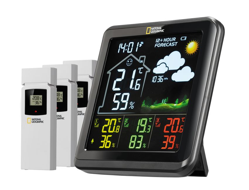
3 Eigenschaften
• Farbiges Display mit grafischer Wettertrendanzeige
• Anzeige der Außensensordaten von allen 3 Sensoren gleichzeitig
• Helligkeitseinstellung (hoch, niedrig, aus)
• Anzeige von Uhrzeit, Datum
• Uhrzeit per DCF-Funkübertragung
• Alarm mit Schlummerfunktion (Snooze)
• Außentemperatur (in °C oder °F)
• Innentemperatur (in °C oder °F)
• Relative Luftfeuchtigkeit (innen und außen) in %
• Luftdruck (mmHg, inHg oder hPa mb)
• Raumklimaindikator
• 3 Thermo-/Hygro-Außensensoren anschließbar (3 Sensoren inkl.)
5 / 52• Zum Aufstellen und für die Wandmontage
4 Zu dieser Anleitung
HINWEIS
Diese Bedienungsanleitung ist als Teil des Gerätes zu betrachten!
Lesen Sie vor der Benutzung des Geräts aufmerksam die Sicherheitshinweise und die Bedienungsan-
leitung.
Bewahren Sie diese Bedienungsanleitung für die erneute Verwendung zu einem späteren Zeitpunkt
auf. Bei Verkauf oder Weitergabe des Gerätes ist die Bedienungsanleitung an jeden nachfolgenden
Besitzer/Benutzer des Produkts weiterzugeben.
5 Teileübersicht und Lieferumfang
1
zZZ
3
2
DST
4 8
DOWN
UP ALARM MEM CH
SET 9
5 7 11
6
10
DC 5.0V
13
A
12
16
14 23
22
17 C
21
18
15
24
19
D
20
B
25
Abb. 1: Alle Teile der Basisstation (oben), Sensor (unten links) und des AC-Netzadapters (unten rechts) in der Übersicht.
6 / 521 SNOOZE/LIGHT-Taste (Schlummerfunktion / 2 Bildschirm
Displayhelligkeit einstellen)
3 Vorrichtung für Wandmontage 4 DOWN-Taste (Wert verringern)
5 UP-Taste (Wert erhöhen) 6 ALARM-Taste
7 MEM-Taste 8 CHANNEL-Taste (Kanalwahl)
9 SET-Taste 10 Batteriefach
11 Batteriefachabdeckung 12 Standfuß
13 DC-Anschlussbuchse für Hohlstecker 14 Display (Funksensor)
15 Funktionsleuchte 16 Vorrichtung für die Wandmontage
17 Batteriefachabdeckung (Funksensor) 18 Schieberegler für die Kanalwahl
19 RESET-Knopf (alle Einstellungen zurückset- 20 Batteriefach (Funksensor)
zen)
21 Euro-Steckeradapter 22 UK-Steckeradapter
23 Adapteraufnahme 24 Arretierungsknopf
25 DC-Hohlstecker
Lieferumfang:
Wetterstation (A), Thermo-/Hygrosensor (B) (3 Stück), 1 x AC-Netzadapter (C) mit 2 x Stecker-Adap-
ter (D)
Außerdem erforderlich (nicht im Lieferumfang enthalten):
Station: 3 Stck. Micro-Batterien (1.5V, Typ AAA)
Sensor: 2 Stck. Micro-Batterien (1.5V, Typ AAA) (6 Stck. insgesamt benötigt)
7 / 526 Displayanzeigen
1 17 16 15
DST
2
14
13
3
18
4 7 10
5
6 8 9 11 12
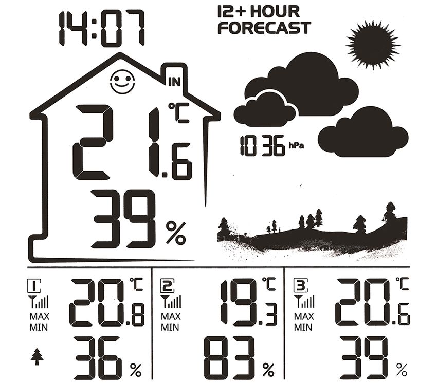
1 Uhrzeit 2 Raumklimaindikator
3 Innentemperatur (in °C oder °F) und Luftfeuch- 4 Empfangssignalstärke Außensensor Kanal 1
tigkeit (in %)
5 Batteriestatus (Sensor Kanal 1) 6 Anzeigebereich für Kanal 1 (gelb) Außentem-
peratur und Luftfeuchtigkeit
7 Empfangssignalstärke Außensensor Kanal 2 8 Batteriestatus (Sensor Kanal 2)
9 Anzeigebereich für Kanal 2 (grün) Außentem- 10 Empfangssignalstärke Außensensor Kanal 3
peratur und Luftfeuchtigkeit
11 Batteriestatus (Sensor Kanal 3) 12 Anzeigebereich für Kanal 3 (rot) Außentempe-
ratur und Luftfeuchtigkeit
13 Luftdruck (mmHg, inHg oder hPa mb) 14 Grafische Wettertrend-Anzeige für die nächs-
ten 12 Stunden
15 Batteriestatus (Basisstation) 16 Symbol für das Funksignal
17 Weckruf aktiv 18 Symbol Höchst- (MAX) oder Tiefstwert (MIN)
8 / 527 Vor der Inbetriebnahme
HINWEIS
Vermeidung von Verbindungsstörungen!
Um Verbindungsstörungen zwischen den Geräten zu vermeiden, sind die folgenden Punkte bei der In-
betriebnahme zu beachten.
1. Basisgerät (Empfänger) und Sensor (Sender) so nah wie möglich nebeneinander stellen/legen.
2. Stromversorgung für das Basisgerät herstellen und warten bis die Innentemperatur angezeigt wird.
3. Stromversorgung für den Sensor herstellen.
4. Basisgerät und Sensor innerhalb des effektiven Übertragungsbereichs aufstellen/betreiben.
5. Sicherstellen, dass Basisgerät und Funksensor auf den gleichen Kanal eingestellt sind.
Bei einem Batteriewechsel stets die Batterien sowohl im Basisgerät als auch im Sensor entfernen und
in richtiger Reihenfolge wieder neu einsetzen, damit die Funkverbindung erneut aufgebaut werden
kann. Wird eines der beiden Geräte über einen Netzstromanschluss betrieben, so muss auch für die-
ses bei einem Batteriewechsel kurzzeitig die Stromverbindung getrennt werden. Werden z.B. nur die
Batterien im Sensor ausgetauscht, kann das Signal anschließend gar nicht oder nicht mehr korrekt
empfangen werden.
Beachten Sie, dass die tatsächliche Reichweite von den jeweils verwendeten Baumaterialien der Ge-
bäude sowie der jeweiligen Position der Basiseinheit und des Außensensors abhängt. Durch externe
Einflüsse (diverse Funksender und andere Störquellen) kann sich die mögliche Reichweite stark ver-
ringern. In solchen Fällen empfehlen wir, sowohl für das Basisgerät als auch den Außensensor andere
Standorte zu suchen. Manchmal reicht schon ein Verschieben um wenige Zentimeter!
8 Die ersten Schritte
Befolgen Sie die Punkte in der angegebenen Reihenfolge, um eine erfolgreiche Einrichtung zu Ge-
währleisten.
1. Stromversorgung herstellen (Basisstation)
2. Sobald die Funksignalsymbole für die Außensensoren blinken, setzen Sie bitte die Batterien sofort
in die Sensoren ein, sonst wechselt die Station irgendwann in die DCF Funksignal Suche. Wäh-
rend der DCF Funksignal Suche können keine Außensensoren verbunden werden. Wenn neue
Außensensoren verbunden werden sollen, bitte wieder bei Punkt 1 beginnen.
3. Wenn das Funksignal neben der Uhrzeit blinkt, wird nach dem DCF Funksignal gesucht. Während
dieser Suche können die Außensensoren nicht verbunden werden. Der DCF Suchvorgang kann
unter Umständen bis zu 15 Minuten dauern und startet dann bei nicht erfolgreicher DCF Verbin-
dung zu jeder Stunde erneut, bis die Verbindung erfolgreich ist.
9 Stromversorgung herstellen
Basisgerät
1. DC-Stecker in die Anschlussbuchse am Basisgerät stecken.
2. Netzstecker in die Steckdose stecken.
3. Das Gerät wird direkt mit Strom versorgt.
4. Warten bis die Innentemperatur auf dem Basisgerät angezeigt wird.
HINWEIS! Für einen dauerhaften Betrieb wird die Stromversorgung über Netzstrom empfoh-
len. Alternativ ist auch ein Betrieb mittels Batterien möglich, um die Zeiteinstellung bei
Stromausfall zu halten. Im Batteriebetrieb wird die Station nach 6 Sekunden in den Strom-
sparmodus versetzt und die Displayanzeige deaktiviert. Durch Betätigen der Snooze-Taste
kann die Displayanzeige wieder aktiviert werden.
9 / 52Für den Batteriebetrieb folgendermaßen vorgehen:
5. Batteriefachdeckel entfernen.
6. Batterien in das Batteriefach einsetzen. Dabei die korrekte Ausrichtung der Batteriepole (+/-) be-
achten.
7. Batteriefachdeckel wieder aufsetzen.
8. Warten bis Innentemperatur auf dem Basisgerät angezeigt wird.
HINWEIS! Beim Wechsel der Stromversorgungsart (Netzstrom oder Batterien) wird die
Stromversorgung technisch bedingt kurzzeitig unterbrochen. Dabei gehen alle zuvor vorge-
nommenen Einstellungen verloren. Ausnahme: dauerhafter Batteriebetrieb.
Funksensor
9. Batteriefachdeckel entfernen.
10. Batterien in das Batteriefach einsetzen. Dabei die korrekte Ausrichtung der Batteriepole (+/-) be-
achten.
11. Kanal-Wahlschalter auf den gewünschten Kanal einstellen.
HINWEIS! Diese Wetterstation kann mit einem oder mehreren Funksensoren betrieben wer-
den. Jeder angeschlossene Funksensor muss auf einem anderen Kanal betrieben werden. Ist
nur ein Funksensor angeschlossen, sollte dieser auf Kanal 1 betrieben werden.
12. Batteriefachdeckel wieder aufsetzen.
10 Automatische Zeiteinstellung
Nachdem die Stromversorgung hergestellt wurde, sucht das Gerät automatisch nach dem Funksignal.
Es dauert etwa 3-8 Minuten bis dieser Prozess abgeschlossen ist.
Bei korrektem Empfang des Funksignals werden Datum und Uhrzeit automatisch eingestellt und das
Empfangssymbol wird angezeigt.
HINWEIS! Während des Funksignalempfangs werden einige Funktionen/Tasten deaktiviert.
Wird kein Funksignal empfangen, folgendermaßen vorgehen:
1. UP-Taste am Basisgerät ca. 3 Sekunden drücken, um den Empfang des Funksignals zu aktivie-
ren. Der Empfang wird nun erneut initialisiert.
2. Wird weiterhin kein Funksignal empfangen, muss die Zeiteinstellung manuell vorgenommen wer-
den.
11 Manuelle Zeiteinstellung
Um Uhrzeit/Datum manuell einzustellen, muss zunächst geprüft werden, ob das Radio Symbol im Dis-
play noch blinkt (der automatische Empfang des Zeitsignals ist dann noch aktiv). Jetzt die UP-Taste
ca. 3 Sekunden drücken, um den Empfang zu deaktivieren.
1. SET-Taste ca. 3 Sekunden drücken um in den Zeiteinstellungsmodus zu gelangen.
2. Die einzustellenden Ziffern blinken.
3. UP- oder DOWN-Taste drücken, um den Wert zu verändern.
4. SET-Taste drücken, um die Eingabe zu bestätigen und zur nächsten Einstellung zu wechseln.
5. Reihenfolge der Einstellungen: Stunden > Minuten > Jahr > Tag/Monat, Monat/Tag > Monat > Tag
> Luftdruckeinheit > Sommerzeit (DST) ein/aus > Zeitversatz (+/- 12 Std.) > Exit
6. SET-Taste abschließend drücken, um Einstellungen zu speichern und den Einstellungsmodus zu
verlassen.
12 Weckrufeinstellung
1. ALARM-Taste drücken, um die Weckzeit anzuzeigen.
10 / 522. ALARM-Taste ca. 2 Sekunden drücken um in den Weckzeiteinstellungsmodus zu gelangen.
3. Die einzustellenden Ziffern blinken.
4. UP- oder DOWN-Taste drücken, um den Wert zu verändern.
5. ALARM-Taste drücken, um die Eingabe zu bestätigen und zur nächsten Einstellung zu wechseln.
6. Reihenfolge der Einstellungen: Stunden > Minuten
7. ALARM-Taste abschließend drücken, um Einstellungen zu speichern und den Einstellungsmodus
zu verlassen.
8. Im normalen Anzeigemodus die ALARM-Taste drücken, um die Weckzeit anzuzeigen.
9. Während der Weckzeit-Anzeige die ALARM-Taste drücken, um den Weckruf zu aktivieren oder zu
deaktivieren.
13 Schlummerfunktion
1. Beim Ertönen des Weckrufs die SNOOZE/LIGHT-Taste drücken, um die Schlummerfunktion zu
aktivieren. Weckruf ertönt erneut nach 5 Minuten.
2. Beim Ertönen des Weckrufs eine beliebige andere Taste drücken, um den Weckruf bis zum erneu-
ten Erreichen der eingestellten Weckzeit auszusetzen.
3. Wird keine Taste gedrückt, schaltet sich der Weckruf automatisch nach 2 Minuten ab.
14 Anzeigenwechsel
• Im normalen Anzeigemodus die DOWN-Taste drücken, um bei der Zeitanzeige zwischen dem 12-
oder 24-Stunden-Modus zu wechseln.
• Im normalen Anzeigemodus die SET-Taste drücken, um zwischen Uhrzeit und Datum zu wech-
seln.
• Im normalen Anzeigemodus die UP-Taste drücken, um bei der Anzeige der Temperatur-Maßein-
heit zwischen °C und °F zu wechseln.
• Im normalen Anzeigemodus die CHANNEL-Taste ca. 3 Sekunden drücken, um die Außensensor-
daten zu löschen und den Sensorempfang erneut zu initialisieren.
• Im normalen Anzeigemodus die MEM-Taste mehrmals drücken, um nacheinander die eingestell-
ten Höchstwerte (Max/Min) anzuzeigen.
• Während der Max/Min Anzeige die MEM-Taste ca. 3 Sekunden drücken, um die Max/Min Daten
zu löschen. Täglich um 0:00 Uhr wird der Max/Min-Datensatz automatisch gelöscht.
• Im normalen Anzeigemodus die ALARM-Taste drücken, um die eingestellte Weckzeit anzuzeigen.
15 Klimaindikator
1 DRY: Trocken (Luftfeuchtigkeit 70%)
Der Klimaindikator ist eine bildliche Anzeige, die auf der Lufttemperatur und Luftfeuchtigkeit basiert,
um das Komfortniveau zu bestimmen.
Hinweis:
11 / 52• Die Komfortanzeige kann bei gleicher Temperatur unterschiedlich ausfallen, abhängig von der
Luftfeuchtigkeit.
• Es gibt keine Komfortanzeige, wenn die Temperatur unter 0 ° C oder über 60 ° C liegt.
16 Wettervorhersage
Die Wettervorhersage wird anhand des Luftdrucks kalibriert und mit 5 Statussymbolen angezeigt: son-
nig, teilweise bewölkt, bewölkt, regnerisch und verschneit.
• Die Wettervorhersage ist für die nächsten 12 Stunden gedacht, sie muss nicht unbedingt die aktu-
elle Situation widerspiegeln.
• Die Genauigkeit einer druckbasierten Wettervorhersage liegt bei etwa 70% bis 75%.
• Die Druckeinheit ist im Zeiteinstellungsmodus wählbar (hPa mb, mmHg, inHg).
17 Anschluss von Funksensoren
Die Wetterstation kann die Messwerte von bis zu 3 Funksensoren des gleichen Typs anzeigen. Dabei
muss jeder Funksensor auf einen separaten Kanal eingestellt sein. Zur Kanaleinstellung folgenderma-
ßen vorgehen:
1. Batteriefachabdeckung des Funksensors entfernen.
2. Kanalwahl-Schalter auf den gewünschten Kanal einstellen (CH1, CH2 oder CH3).
3. Batteriefachabdeckung wieder aufsetzen.
4. HINWEIS! Jeder angeschlossene Funksensor muss auf einen anderen Kanal eingestellt wer-
den. Ist nur ein Funksensor angeschlossen, sollte dieser auf CH1 eingestellt werden.
5. CHANNEL-Taste ca. 3 Sekunden drücken, um die Werte zurückzusetzen und nach einem Funk-
sensor (RF-Signal) zu suchen.
12 / 5218 MAX/MIN Wetterdaten
Die Basisstation speichert die Höchst- und Tiefstwerte für die Innen- und Außentemperatur sowie die
Innenraum-Luftfeuchtigkeit über einen Zeitraum von 24 Stunden:
1. Die MEM-Taste mehrmals drücken, um nacheinander die gespeicherten Werte der Basisstation
und des aktuell eingestellten Funksensors anzuzeigen.
2. Reihenfolge der Anzeige: Höchstwerte (MAX) > Tiefstwerte (MIN) > Aktuelle Werte
3. MEM-Taste ca. 3 Sekunden drücken, um die Werte des aktuellen Aufzeichnungszeitraums zu lö-
schen.
HINWEIS! Bei einem Batteriewechsel werden ebenfalls alle Werte des aktuellen Aufzeichnungs-
zeitraums gelöscht.
19 Helligkeit der Displayanzeige regulieren
1. Bei Batteriebetrieb die SNOOZE/LIGHT-Taste drücken, um das Display für etwa 7 Sekunden zu
aktivieren.
2. Im Netzbetrieb (DC 5V) die SNOOZE/LIGHT-Taste mehrmals drücken, um die gewünschte Dis-
playhelligkeit in Stufen einzustellen: schwach – hell – aus
3. HINWEIS! Im Batteriebetrieb ist keine Regulierung der Displayhelligkeit möglich.
20 Entsorgung
Entsorgen Sie die Verpackungsmaterialien sortenrein. Informationen zur ordnungsgemäßen
Entsorgung erhalten Sie beim kommunalen Entsorgungsdienstleister oder Umweltamt.
Werfen Sie Elektrogeräte nicht in den Hausmüll!
Gemäß der Europäischen Richtlinie 2012/19/EG über Elektro- und Elektronik-Altgeräte und
deren Umsetzung in nationales Recht müssen verbrauchte Elektrogeräte getrennt gesam-
melt und einer umweltgerechten Wiederverwertung zugeführt werden.
Batterien und Akkus dürfen nicht im Hausmüll entsorgt werden. Sie sind zur Rückgabe ge-
brauchter Batterien und Akkus gesetzlich verpflichtet und können die Batterien nach Ge-
brauch entweder in unserer Verkaufsstelle oder in unmittelbarer Nähe (z.B. im Handel oder in
kommunalen Sammelstellen) unentgeltlich zurückgeben.
Batterien und Akkus sind mit einer durchgekreuzten Mülltonne sowie dem chemischen Sym-
bol des Schadstoffes bezeichnet, "Cd" steht für Cadmium, "Hg" steht für Quecksilber und "Pb"
steht für Blei.
21 Technische Daten
Basisstation
Stromversorgung 5V DC 150mA USB Netzstecker
Backup: 3x AAA
Temperatur-Maßeinheit °C / °F
Temperatur-Messbereich von -10°C bis 50°C
Luftfeuchtigkeits-Messbereich RH 20% bis 90%
Zeitanzeige HH:MM
13 / 52Zeitformate 12 oder 24 Stunden
Kalenderanzeige TT/MM
Zeitsignal DCF
Maße 143 x 143 x 26 mm (B x H x T)
Gewicht (inkl. Batterien) 295 g
Funksensor
Batterien 2x AAA, 1.5V
Maximale Anzahl der Sensoren 3
RF Übertragungsfrequenz 433 Mhz
RF Übertragungsreichweite 80 m
Maximale Sendeleistung < 10mW
Temperatur-Messbereich von -40°C bis 60°C (23°F bis 122°F)
Luftfeuchtigkeits-Messbereich RH 20% bis 95%
Maße 40 x 120 x 21 mm (B x H x T)
Gewicht (inkl. Batterien) 76 g
22 Garantie
Die reguläre Garantiezeit beträgt 2 Jahre und beginnt am Tag des Kaufs. Um von einer verlängerten,
freiwilligen Garantiezeit wie auf dem Geschenkkarton angegeben zu profitieren, ist eine Registrierung
auf unserer Website erforderlich.
Die vollständigen Garantiebedingungen sowie Informationen zu Garantiezeitverlängerung und Ser-
viceleistungen können Sie unter www.bresser.de/garantiebedingungen einsehen.
23 EG-Konformitätserklärung
Hiermit erklärt Bresser GmbH, dass der Funkanlagentyp mit Artikelnummer 9070710 der
Richtlinie 2014/53/EU entspricht. Der vollständige Text der EG-Konformitätserklärung ist
unter der folgenden Internetadresse verfügbar: www.bresser.de/download/9070710/
CE/9070710_CE.pdf
14 / 52Table of contents
1 Imprint ........................................................................................................................................................... 16
2 Validity note .................................................................................................................................................. 16
3 Features ........................................................................................................................................................ 16
4 About this Instruction Manual..................................................................................................................... 17
5 Parts overview and scope of delivery ........................................................................................................ 17
6 Screen display .............................................................................................................................................. 19
7 Before commissioning................................................................................................................................. 20
8 The first steps............................................................................................................................................... 20
9 Power supply ................................................................................................................................................ 20
10 Automatic time setting................................................................................................................................. 21
11 Manual time setting...................................................................................................................................... 21
12 Alarm setting ................................................................................................................................................ 22
13 Snooze function ........................................................................................................................................... 22
14 Display change ............................................................................................................................................. 22
15 Clima indicator ............................................................................................................................................. 22
16 Weather forecast .......................................................................................................................................... 23
17 Connecting remote sensors........................................................................................................................ 23
18 MAX/MIN Weather data ................................................................................................................................ 24
19 Display brightness regulation..................................................................................................................... 24
20 Disposal ........................................................................................................................................................ 24
21 Technical data .............................................................................................................................................. 24
22 Warranty........................................................................................................................................................ 25
23 EC declaration of conformity ...................................................................................................................... 25
24 UKCA declaration of conformity................................................................................................................. 25
151 Imprint
Bresser GmbH
Gutenbergstr. 2
46414 Rhede
Germany
www.bresser.de
For any warranty claims or service inquiries, please refer to the information on "Warranty" and "Ser-
vice" in this documentation. We ask for your understanding that unsolicited returns cannot be pro-
cessed.
Errors and technical changes excepted.
© 2023 Bresser GmbH
All rights reserved.
The reproduction of this documentation - even in extracts - in any form (e.g. photocopy, print, etc.) as
well as the use and distribution by means of electronic systems (e.g. image file, website, etc.) without
the prior written permission of the manufacturer is prohibited.
The designations and brand names of the respective companies used in this documentation are gen-
erally protected by trade, trademark and/or patent law in Germany, the European Union and/or other
countries.
© National Geographic Partners LLC. All rights reserved.
NATIONAL GEOGRAPHIC and Yellow Border Design are trademarks of National Geographic Society,
used under license.
Visit our website: www.nationalgeographic.com
2 Validity note
This documentation is valid for the products with the following article numbers:
9070710
Manual version: v022023a
Manual designation:
Manual_9070710_Weather-station-VA-Colour-RC_de-en-fr-es_NATGEO_v022023a
Always provide information when requesting service.
3 Features
• Colour display with graphical weather trend indicator
• Display outdoor sensor data from all 3 sensors simultaneously
• Brightness setting (high, low, off)
• Display of time, date
• Time information via DCF radio transmission
• Alarm clock with snooze function
• Outdoor temperature (in °C or °F)
• Indoor temperature (in °C or °F)
• Relative humidity (indoor and outdoor) in %
• Atmospheric pressure (mmHg, inHg or hPa mb)
• Indoor climate indicator
• 3 thermo/hygro outdoor sensors can be connected (3 sensor included)
16 / 52• Table stand or wall mounting
4 About this Instruction Manual
NOTICE
These operating instructions are to be considered a component of the device.
Read the safety instructions and the instruction manual carefully before using this device.
Keep these instruction manual in a safe place for future reference. If the device is sold or passed on,
the instruction manual must be passed on to any subsequent owner/user of the product.
5 Parts overview and scope of delivery
1
zZZ
3
2
DST
4 8
DOWN
UP ALARM MEM CH
SET 9
5 7 11
6
10
DC 5.0V
13
A
12
16
14 23
22
17 C
21
18
15
24
19
D
20
B
25
Illustration 1: All parts of the base station (top), sensor (bottom left) and AC power adapter (bottom right) in overview.
1 SNOOZE/LIGHT button (set snooze function / 2 Display
display brightness)
3 Wall mount fixture 4 DOWN button (decrease value)
17 / 525 UP button (increase value) 6 ALARM button
7 MEM button 8 CHANNEL button (channel selection)
9 SET button 10 Battery compartment
11 Battery compartment cover 12 Stand
13 DC connection socket for barrel connector 14 Display (wireless sensor)
15 Function indicator 16 Wall mount fixture
17 Battery compartment cover (wireless sensor) 18 Slide control for channel selection
19 RESET button (rest all settings) 20 Battery compartment (wireless sensor)
21 Euro plug adapter 22 UK plug adapter
23 Adapter fixture 24 Locking knob
25 DC barrel connector
Scope of delivery:
Weather station (A), Thermo-/Hygrosensor (B) (3 pieces), 1 x AC power adapter (C) with 2 x plug ad-
apters (D)
Also required (not included):
Station: 3 pcs. Micro batteries (1.5V, type AAA)
Sensor: 2 pcs. Micro batteries (1.5V, type AAA) (6 pcs. total required)
18 / 526 Screen display
1 17 16 15
DST
2
14
13
3
18
4 7 10
5
6 8 9 11 12
1 Time 2 Indoor climate indicator
3 Indoor temperature (in °C or °F) and humidity 4 Signal strength for outdoor sensor channel 1
(in %)
5 Battery status (sensor channel 1) 6 Display section for channel 1 (yellow) Outdoor
temperature and humidity
7 Signal strength for outdoor sensor channel 2 8 Battery status (sensor channel 2)
9 Display section for channel 2 (green) Outdoor 10 Signal strength for outdoor sensor channel 3
temperature and humidity
11 Battery status (sensor channel 3) 12 Display section for channel 3 (red) Outdoor
temperature and humidity
13 Atmospheric pressure (mmHg, inHg or hPa 14 Graphical weather trend display for the next
mb) 12 hours
15 Battery status (base station) 16 Symbol for radio signal
19 / 5217 Symbol for active alarm 18 Symbol for highest (MAX) or lowest (MIN)
value
7 Before commissioning
NOTICE
Avoid connection faults!
In order to avoid connection problems between the devices, the following points must be observed
during commissioning.
1. Place the base unit (receiver) and sensor (transmitter) as close together as possible.
2. Connect the power supply to the base unit and wait until the indoor temperature is displayed.
3. Establish power supply for the sensor.
4. Set up/operate the base unit and sensor within the effective transmission range.
5. Make sure that the base unit and the radio sensor are set to the same channel.
When changing the batteries, always remove the batteries from both the base unit and the sensor and
reinsert them in the correct order so that the radio link can be re-established. If one of the two devices
is operated via a mains power connection, the power connection must also be briefly disconnected for
this device when the batteries are changed. If, for example, only the batteries in the sensor are re-
placed, the signal may subsequently not be received at all or not be received correctly.
Note that the actual range depends on the respective construction materials used for the buildings as
well as the respective position of the base unit and the outdoor sensor. External influences (various ra-
dio transmitters and other sources of interference) can greatly reduce the possible range. In such
cases, we recommend finding other locations for both the base unit and the outdoor sensor. Some-
times moving the sensor by just a few centimeters is enough!
8 The first steps
Follow the bullet points in order, to ensure a successful setup.
1. Setting up power supply (base station)
2. As soon as the radio signal icons for the outdoor sensors start flashing, insert the batteries into the
sensors immediately, otherwise the station will eventually switch to DCF radio signal search. No
outdoor sensors can be connected during the DCF radio signal search. If new outdoor sensors are
to be connected, please start from point 1 again.
3. When the radio signal next to the time flashes, the DCF radio signal is being searched for. During
this search, the outdoor sensors cannot be connected. The DCF search process may take up to
15 minutes and then restarts every hour if the DCF connection is not successful until the connec-
tion is successful.
9 Power supply
Base unit
1. Insert the DC plug into the connection socket on the base unit.
2. Insert the Euro plug into the mains power socket.
3. The device is powered on directly.
4. Wait until indoor temperature is displayed on the base unit.
20 / 52NOTICE! For permanent operation, mains power supply is recommended. Alternatively, op-
eration using batteries is also possible to maintain the time setting in the event of a power
failure. In battery operation, the station is set to power saving mode after 6 seconds and the
display indication is deactivated. The display can be reactivated by pressing the snooze but-
ton.
For battery operation, proceed as follows:
5. Remove the battery compartment cover.
6. Insert batteries into the battery compartment. Make sure that the batteries are correctly aligned
(+/- poles).
7. Replace the battery compartment cover.
8. Wait until indoor temperature is displayed on the base unit.
NOTICE! When changing the type of power supply (mains power or batteries), the power
supply is temporarily interrupted for technical reasons. All previously made settings will be
lost.
Wireless sensor
9. Remove the battery compartment cover.
10. Insert batteries into the battery compartment. Make sure that the batteries are correctly aligned
(+/- poles).
11. Move the channel slider to the desired channel.
NOTICE! This weather station can be operated with one or more wireless sensors. Each con-
nected wireless sensor must be operated on a different channel. If only one wireless sensor is
connected, it should be operated on channel 1.
12. Replace the battery compartment cover.
10 Automatic time setting
After the power is restored, the unit automatically searches for the radio signal. It takes approximately
3-8 minutes for this process to complete.
If the radio signal is received correctly, the date and time are set automatically and the reception sym-
bol is displayed.
NOTICE! Some functions/buttons are deactivated during radio signal reception.
If no radio signal is received, proceed as follows:
1. Press the UP button on the base unit for approx. 3 seconds to activate reception of the radio sig-
nal. Reception is now initialized again.
2. If still no radio signal is received, the time must be set manually.
11 Manual time setting
To set the time/date manually, first check whether the radio symbol in the display is still flashing (auto-
matic reception of the time signal is then still active). Now press the UP button for approx. 3 seconds
to deactivate reception.
1. Press the SET button for approx. 3 seconds to enter the time setting mode.
2. Digits to be set are flashing.
3. Press UP or DOWN button to change the value.
4. Press the SET button to confirm and switch to the next setting.
5. Sequence of the settings: Hours > minutes > year > day/month, month/day > month > day > air
pressure unit > Daylight saving time (DST) on/off > time offset (+/- 12 hours) > exit
6. Finally, press the SET button to save the settings and exit settings mode.
21 / 5212 Alarm setting
1. Press the ALARM button to display the alarm time.
2. Press the ALARM button for approx. 2 seconds to enter the alarm time settings mode.
3. Digits to be set are flashing.
4. Press UP or DOWN button to change the value.
5. Press the ALARM button to confirm the entry and move to the next setting.
6. Sequence of the settings: Hours > minutes
7. Finally, press the ALARM button to save the settings and exit the setting mode.
8. In normal display mode, press the ALARM button to display the currently set alarm time.
9. While the alarm is displayed, press the ALARM button to enable or disable the alarm.
13 Snooze function
1. When the alarm sounds, press the SNOOZE/LIGHT button to activate the snooze function. The
alarm sounds again after 5 minutes.
2. When the alarm sounds, press any other key to stop the alarm until the set alarm time is reached
again.
3. If no key is pressed, the alarm is automatically switched off after 2 minutes.
14 Display change
• In normal display mode, press the DOWN button to toggle the time display between 12-hour or 24-
hour mode.
• In normal display mode, press the SET button to switch between time and date.
• In normal display mode, press the UP button to toggle between °C and °F when displaying the
temperature unit.
• In normal display mode, press the CHANNEL button for about 3 seconds to clear the outdoor
sensor data and reinitialize sensor reception.
• In normal display mode, press the MEM button several times to display the set Max/Min values
one after another.
• During the Max/Min display, press the MEM button for about 3 seconds to clear the Max/Min data.
Every day at 0:00 a.m. the max/min data record is automatically deleted.
• In normal display mode, press the ALARM button to display the currently set alarm time.
15 Clima indicator
1 DRY: dry (humidity 70%)
The climate indicator is a visual display based on air temperature and humidity to determine the level
of comfort.
22 / 52Note:
• The comfort display may vary at the same temperature, depending on the humidity.
• There is no comfort display if the temperature is below 0°C or above 60°C.
16 Weather forecast
The weather forecast is calibrated according to the air pressure and displayed with 5 status symbols:
sunny, partly cloudy, cloudy, rainy and snowy.
• The weather forecast is intended for the next 12 hours, it does not necessarily reflect the current
situation.
• The accuracy of a pressure-based weather forecast is about 70% to 75%.
• The pressure unit is selectable in time setting mode (hPa mb, mmHg, inHg).
17 Connecting remote sensors
The Weather Station can display the readings from up to 3 wireless sensors of the same type. Each
radio sensor must be set to a separate channel. Proceed as follows to set the channel:
1. Remove the battery compartment cover of the wireless sensor.
2. Set the channel selection switch to the desired channel (CH1, CH2 or CH3).
3. Re-attach the battery compartment cover.
4. NOTICE! Each connected wireless sensor must be set to a different channel. If only one wire-
less sensor is connected, it should be set to CH1.
5. Press CHANNEL button for about 3 seconds to reset the values and search for a wireless sensor
(RF signal).
23 / 5218 MAX/MIN Weather data
Maximum and minimum indoor and outdoor temperatures as well as indoor humidity are stored by the
main unit over a period of 24 hours:
1. Press the MEM button repeatedly to display the stored values of the main unit and of the currently
set outdoor sensor one after another.
2. Display sequence: Maximum values (MAX) > Minimum values (MIN) > Current values
3. Press the MEM button for approx. 3 seconds to delete the values of the current recording period.
NOTICE! All values of the current recording period are also deleted with a battery change.
19 Display brightness regulation
1. When using battery power, press the SNOOZE/LIGHT button to activate the display for about 7
seconds.
2. In mains operation (DC 5V), touch the SNOOZE/LIGHT touch surface several times to set the de-
sired display brightness in steps: dim - bright - off
3. NOTE! It is not possible to adjust the display brightness in battery operation.
20 Disposal
Dispose of the packaging materials according to its type. Information on proper disposal can
be obtained from the municipal waste disposal service provider or environmental agency.
Do not dispose of electronic devices in the household garbage!
According to the European Directive 2012/19/EU on Waste Electrical and Electronic Equip-
ment and its transposition into national law, used electrical equipment must be collected sep-
arately and recycled in an environmentally sound manner.
Batteries and rechargeable batteries must not be disposed of with household waste. You are
legally obliged to return used batteries and accumulators and can return them after use either
at our sales outlet or in the immediate vicinity (e.g. in the trade or in municipal collection
points) free of charge.
Batteries and accumulators are marked with a crossed-out dustbin and the chemical symbol of
the pollutant, "Cd" stands for cadmium, "Hg" stands for mercury and "Pb" stands for lead.
21 Technical data
Base unit
Power supply 5V DC 150mA USB power plug
Backup: 3x AAA
Temperature unit °C/°F
Temperature measuring range from -10°C to 50°C
Humidity measuring range RH 20% to 90 %
Time display HH:MM
Time format 12 or 24 hours
Calendar display DD/MM
Time signal DCF
24 / 52Dimensions 143 x 143 x 26 mm (W x H x D)
Weight (incl. batteries) 295 g
Wireless sensor
Batteries 2x AAA, 1.5V
Maximum number of sensors 3
RF transmission frequency 433 MHz
RF transmission range 80 m
Maximum RF power < 10mW
Temperature measuring range from -40°C to 60°C (23°F bis 122°F)
Humidity measuring range RH 20% to 95 %
Dimensions 40 x 120 x 21 mm (W x H x D)
Weight (incl. batteries) 76 g
22 Warranty
The regular warranty period is 2 years and starts on the day of purchase. To benefit from an extended
voluntary warranty period as indicated on the gift box, registration on our website is required.
You can consult the full guarantee terms as well as information on extending the guarantee period and
details of our services at www.bresser.de/warranty_terms.
23 EC declaration of conformity
Bresser GmbH hereby declares that the radio equipment type with item number 9070710
is in compliance with Directive 2014/53/EU. The full text of the EC Declaration of Conform-
ity is available at the following web address: www.bresser.de/download/9070710/
CE/9070710_CE.pdf
24 UKCA declaration of conformity
A "Declaration of Conformity" in accordance with the applicable directives and relevant
standards has been issued by Bresser GmbH The full text of the UKCA Declaration of
Conformity is available at the following web address: www.bresser.de/download/9070710/
UKCA/9070710_UKCA.pdf
Bresser UK Ltd. • Suite 3G, Eden House, Enterprise Way, Edenbridge, Kent TN8 6HF,
Great Britain
25 / 52Table des matières 1 Impressum .................................................................................................................................................... 27 2 Note de validité............................................................................................................................................. 27 3 Caractéristiques ........................................................................................................................................... 27 4 A propos de ce mode d’emploi ................................................................................................................... 28 5 Vue d'ensemble des pièces et étendue de la livraison............................................................................. 28 6 Affichage à l'écran........................................................................................................................................ 30 7 Avant la mise en service.............................................................................................................................. 31 8 Premières étapes.......................................................................................................................................... 31 9 Source d’alimentation.................................................................................................................................. 31 10 Réglage automatique de l'heure ................................................................................................................. 32 11 Réglage manuel de l'heure .......................................................................................................................... 32 12 Réglage de l'alarme...................................................................................................................................... 33 13 Fonction de répétition du réveil (snooze) .................................................................................................. 33 14 Changement d'affichage.............................................................................................................................. 33 15 Indication Confort ........................................................................................................................................ 34 16 Prévisions météorologiques ....................................................................................................................... 34 17 Raccordement de capteurs sans fil............................................................................................................ 35 18 MAX/MIN Données météorologiques.......................................................................................................... 35 19 Régulation de la luminosité de l'écran ....................................................................................................... 35 20 Recyclage...................................................................................................................................................... 35 21 Données techniques .................................................................................................................................... 36 22 Garantie......................................................................................................................................................... 36 23 Déclaration de conformité CE ..................................................................................................................... 36 26
1 Impressum
  Bresser GmbH
  Gutenbergstr. 2
  46414 Rhede
  Germany
  www.bresser.de
  Pour toute demande de garantie ou de service, veuillez vous référer aux informations sur la "Garantie"
  et le "Service" dans cette documentation. Nous vous demandons de comprendre que les retours non
  sollicités ne peuvent être traités.
  Sous réserve d’erreurs et de modifications techniques.
  © 2023 Bresser GmbH
  Tous droits réservés.
  La reproduction de cette documentation - même partielle - sous quelque forme que ce soit (par ex.
  photocopie, impression, etc.) ainsi que l'utilisation et la diffusion au moyen de systèmes électroniques
  (par ex. fichier image, site Internet, etc.) sans l'autorisation écrite préalable du fabricant sont interdites.
  Les désignations et les marques des sociétés respectives utilisées dans cette documentation sont gé-
  néralement protégées par le droit commercial, le droit des marques et/ou le droit des brevets en Alle-
  magne, dans l'Union européenne et/ou dans d'autres pays.

  Visit our website www.nationalgeographic.com
  © National Geographic Partners LLC. All rights reserved.
  NATIONAL GEOGRAPHIC and Yellow Border Design are trademarks of National Geographic Society,
  used under license.

2 Note de validité
  Cette documentation est valable pour les produits portant les numéros d'article suivants :
  9070710
  Version du manuel : v022023a
  Désignation du manuel :
  Manual_9070710_Weather-station-VA-Colour-RC_de-en-fr-es_NATGEO_v022023a
  Toujours fournir des informations lors de la demande de service.

3 Caractéristiques
   • Ecran couleur avec affichage graphique de la tendance météo
   • Affichage des données des capteurs extérieurs des 3 capteurs simultanément
   • Réglage de la luminosité (élevée, faible, éteinte)
   • Affichage Heure, Date
   • Informations sur l'heure par transmission radio DCF
   • Réveil avec fonction snooze
   • Température extérieure (en ° C ou ° F)
   • Température intérieure (en °C ou °F)
   • Humidité relative (intérieure et extérieure) en %
   • Pression atmosphérique (mmHg, inHg ou hPa mb)
   • Indicateur de climat ambiant
   • 3 capteurs thermo/hygro extérieurs peuvent être connectés (3 capteurs inclus)

                                                                                                          27 / 52
• Support de table ou montage mural
4 A propos de ce mode d’emploi
INFORMATION
Ce mode d’emploi fait partie intégrante de l’appareil.
Lire attentivement les consignes de sécurité et le mode d'emploi avant d'utiliser l'appareil.
Conservez ce manuel d'instructions dans un endroit sûr pour pouvoir le consulter ultérieurement. En
cas de vente ou de cession de l'appareil, le manuel d'instructions doit être transmis à tout propriétaire/
utilisateur ultérieur du produit.
5 Vue d'ensemble des pièces et étendue de la
livraison
1
zZZ
3
2
DST
4 8
DOWN
UP ALARM MEM CH
SET 9
5 7 11
6
10
DC 5.0V
13
A
12
16
14 23
22
17 C
21
18
15
24
19
D
20
B
25
Fig. 1: Toutes les parties de la station de base (en haut) et du capteur sans fil (en bas)
28 / 521 Bouton SNOOZE/LIGHT (fonction de répéti- 2 Écran d'affichage
tion / réglage de la luminosité de l'écran)
3 Fixation murale 4 Bouton DOWN (diminuer la valeur)
5 Bouton UP (augmenter la valeur) 6 Bouton ALARM
7 Bouton MEM 8 Bouton CHANNEL (sélection du canal)
9 (Alarme) Bouton Set 10 Compartiment des piles
11 Couvercle du compartiment des piles 12 Support de table
13 Prise de connexion DC adaptateur secteur 14 Affichage (capteur)
15 Indicateur de fonctionnement 16 Couvercle du compartiment des piles
17 Fixation murale 18 Compartiment des piles
19 Bouton RESET (réinitialiser tous les para- 20 Curseur pour la sélectiondu canal
mètres)
21 Adaptateur de prise européenne 22 Adaptateur de prise UK
23 Logement de l'adaptateur 24 Bouton de blocage
25 Connecteur d'alimentation coaxial
Contenu de la livraison :
Station météorologique (A), Thermo-/Hygro-capteur (B) (3 pièce), 1 x adaptateur secteur AC (C) avec
2 x adaptateurs mâles (D)
Également requis (non inclus) :
Station : 3 pcs. Piles (1,5V, type AAA)
Capteur : 3 pcs. Piles (1,5V, type AAA) (6 pcs. total requis)
29 / 526 Affichage à l'écran
1 17 16 15
DST
2
14
13
3
18
4 7 10
5
6 8 9 11 12
1 Heure 2 Indicateur de climat ambiant
3 Température intérieure (en °C ou °F) et humi- 4 Puissance du signal du canal 1 du capteur ex-
dité (en %) térieur
5 État de la batterie (canal 1 du capteur) 6 Section d'affichage pour le canal 1 (jaune)
Température et humidité extérieures
7 Puissance du signal du canal 2 du capteur ex- 8 État de la batterie (canal 2 du capteur)
térieur
9 Section d'affichage pour le canal 2 (vert) Tem- 10 Puissance du signal du canal 3 du capteur ex-
pérature et humidité extérieures térieur
11 État de la batterie (canal 3 du capteur) 12 Section d'affichage pour le canal 3 (rouge)
Température et humidité extérieures
13 Pression atmosphérique (mmHg, inHg ou hPa 14 Affichage graphique des tendances météoro-
mb) logiques pour les 12 prochaines heures
15 État de la batterie (station de base) 16 Symbole du signal radio
30 / 52Sie können auch lesen