Typ 7110 Betriebsanleitung Manuel d'utilisation - Operating Instructions - Schubert & Salzer Control Systems

Die Seite wird erstellt Sibylle-Barbara Bühler
 
WEITER LESEN
Typ 7110 Betriebsanleitung Manuel d'utilisation - Operating Instructions - Schubert & Salzer Control Systems
Betriebsanleitung

                    Operating Instructions

                    Manuel d'utilisation

                      Typ 7110

Version: 07/2021
                        Bunsenstrasse             D-85053 Ingolstadt
M7110-def.doc           Tel: (0841) 9654-0        Fax: (0841) 9654-590
Art.-Nr: 110 7110       www.schubert-salzer.com

                                   1
Typ 7110 Betriebsanleitung Manuel d'utilisation - Operating Instructions - Schubert & Salzer Control Systems
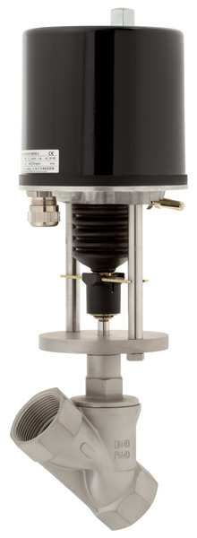
Inhalt/Content/Sommaire
1           Betriebsanleitung (deutsch) ...................................................... 3
    1.1    Ersatzteilliste                                                                   3
    1.2    Technische Daten                                                                  4
    1.3    Einbau                                                                            4
    1.4    Empfohlene Drehmomente für die Kopfstückmontage                                   5
    1.5    Elektrischer Anschluss                                                            6
    1.6    Schaltpläne                                                                       7
    1.7    Justage des Antriebs                                                              12
    1.8    Handbetätigung                                                                    17
    1.9    Demontage und Montage des Antriebs                                                19
    1.10   Demontage und Montage des Ventils                                                 19
    1.11   Entsorgung                                                                        19
    1.12   Schmier- und Klebeplan                                                            20

2                  Operating Instructions (English) ..................................... 21
    2.1    Spare Parts List                                                                  21
    2.2    Technical Data                                                                    22
    2.3    Installation                                                                      22
    2.4    Torque recommendations for head assembly                                          23
    2.5    Electrical Connection                                                             24
    2.6    Wiring Diagrams                                                                   24
    2.7    Adjusting the Actuator                                                            29
    2.8    Manual Override                                                                   35
    2.9    Dismantling and Assembling the Actuator                                           36
    2.10   Dismantling and Assembling the Valve                                              36
    2.11   Lubrication and Bonding Plan                                                      37
    2.12   Disposal                                                                          38

3            Instructions de service (français) ........................................... 39
    3.1    Liste des pièces de rechange                                                      39
    3.2    Caractéristiques techniques                                                       40
    3.3    Pose                                                                              40
    3.4    Couples recommandés pour le montage du corps presse-étoupe                        41
    3.5    Raccordement électrique                                                           42
    3.6    Schémas électriques                                                               43
    3.7    Réglage de l’actionneur                                                           48
    3.8    Commande manuelle                                                                 54
    3.9    Démontage et montage de l’actionneur                                              54
    3.10   Démontage et montage de la vanne                                                  55
    3.11   Plan de graissage et de collage                                                   56
    3.12   Gestion des déchets                                                               57
                                                     2
1                       Betriebsanleitung (deutsch)
1.1                    Ersatzteilliste

      (Nur original Ersatzteile von Schubert & Salzer verwenden!)

      69   El.Antrieb . . .

                                     y%
                                     100
                                     75
                                     50
                                     25
                                      0

                                                                          Säule    71
      7    Scheibe geschlitzt                                           Flansch    70
      29   Druckring kpl.                                           Führungsring   34
      31   Kegelformdichtung                                    Skt.Mutter M8      72
      32   Stützring                                          Scheibe f. Feder     40
      28   Feder f. Packung                                     Kolbenstange       13
      3    Dichtung für Kopfstück                                   Führungsring   34
      4    Kegel                                                      Kopfstück    2
      5    Dichtung f. Kegel                                           Gehäuse     1
      6    Regelkegel

                                           3
1.2       Technische Daten
Technische Daten des Ventils:

Gehäusewerkstoff                Messing                Bronze (Rg 5)       Edelstahl
Nennweiten                   DN 65 bis DN 80          DN 15 bis DN 50   DN 15 bis DN 80
Anschlüsse:
Rohrgewinde
nach ISO 228-1                    2 1/2" - 3"            1/2" - 2"         1/2" - 3"
NPT Gewinde                       2 1/2" - 3"            1/2" - 2"         1/2" - 3"
Schweißenden                           -                     -             1/2" - 3"
Nenndruck                           PN 16                 PN 16             PN 40
Zul. Betriebstemperaturen       -30°C bis 170°C       -30°C bis 200°C   -30°C bis 200°C
Umgebungstemp.              -10°C bis +60°C
Viskosität                  maximal 600 mm²/s (600 cSt)
Vakuum                      maximal 0,001 bar, absolut
Betriebsdruck für
                            maximal 12 bar
totraumarme Ausf.
Leckage Packung             TA-Luft geprüft gemäß DIN EN ISO 15848-1 und VDI 2440
Baulänge Flanschventil      L nach DIN EN 558-92 (alt: DIN 3202-F3)

Technische Daten des Motors:

Stellkraft           0,9 kN; 2,0 kN
Betriebsart
                     S1 - 100 % ED
nach VDE 0530
Netzanschlüsse       230 V 50 Hz - Einphasen-Wechselstrom
                     24 V 50 Hz - Einphasen-Wechselstrom
Aufnahmeleistung     2,6W; 0,9 kN: 4,8W; 2,0 kN: 6,6W
Umgebungstemp.       0 bis 60 °C
Einbaulage           Motor nicht nach unten; ( 0.9kN beliebig)
Schutzart            IP65
(DIN 40050)

1.3       Einbau
Von der Armatur sind alle Verpackungsmaterialien zu entfernen.

Vor dem Einbau ist die Rohrleitung auf Verunreinigung und Fremdkörper zu untersuchen und
ggf. zu reinigen.

Die Rohrleitungen sind spannungsfrei an die einzubauende Armatur anzuschließen.
Die Rohrleitung darf dabei keinesfalls an die Armatur herangezogen werden.

Bei Gehäusen mit Muffenanschluss sind die Gewinde mit einem geeigneten Dichtungsmaterial
abzudichten.

                                                  4
Wird die Armatur in die Rohrleitung eingeschweißt, so sind die Enden vorerst nur zu heften.
Zum Fertigschweißen sind der Antrieb und das Kopfstück vom Gehäuse abzuschrauben um
Beschädigungen an den Dichtelementen zu vermeiden.

Bei Schweißarbeiten an den Rohrleitungen muss der Abstand zur Armatur mindestens 50 cm
betragen, da sonst die Gefahr einer Beschädigung des Sitzes besteht.

Die Funktion der kompletten eingebauten Armatur ist vor der Inbetriebnahme der Anlage zu
überprüfen.

Die Einbaulage ist beliebig.

1.4       Empfohlene Drehmomente für die Kopfstückmontage

Das Kopfstück ist mit einem Drehmoment auf dem Gehäuse zu verschrauben, das eine
ausreichende Verpressung der Kopfstückdichtung gewährleistet.
Folgende Drehmomente (Richtwerte) sollten bei der Montage des Kopfstücks eingehalten
werden.

                                               Kopfstückdichtung
      Nennweite           Graphit (Standard)     Top Chem 2000           PTFE mit 25%
                                                 Klingersil C4400          Glasfaser
 DN 15     ½“                  45 Nm                  60 Nm                  60 Nm
 DN 20     ¾“                  70 Nm                  90 Nm                  90 Nm
 DN 25     1“                  100 Nm                120 Nm                 120 Nm
 DN 32     1 ¼“                150 Nm                150 Nm                 150 Nm
 DN 40     1 ½“                180 Nm                190 Nm                 190 Nm
 DN 50     2“                  200 Nm                230 Nm                 230 Nm
 DN 65     2 ½“                220 Nm                260 Nm                 260 Nm
 DN 80     3“                  260 Nm                310 Nm                 310 Nm

             Bei Einhaltung der angegebenen Drehmomente wird eine Leckagerate
             der Kopfstückdichtung von weniger als 5 x 10⁻³ mbar*l/s über den
             gesamten Temperaturbereich des Ventils erzielt.

             Bei Kopfstückdichtungen aus Klinger Top-Chem, Klingersil C4400 und
             PTFE mit Glasfaser sollten die Dichtungen nach einiger Zeit noch
             einmal nachgezogen werden, da sich die Verpressung durch die
             Fließeigenschaften dieser Werkstoffe verringern kann.

             Bei Ventilen, die für den Einsatz mit gefährlichen Gasen (z.B.
             Sauerstoff oder Ozon) bestimmt sind, müssen diese Anzugsmomente
             unbedingt eingehalten und mit einem Drehmomentschlüssel kontrolliert
             werden.

             Bei Dichtung für Kopfstück aus TopChem oder PTFE mit Glasfasern
             keine Montagepaste auf die Dichtungsfläche und Dichtung auftragen.

                                               5
1.5      Elektrischer Anschluss

                Der elektrische Anschluß darf nur durch qualifiziertes Personal erfolgen.
                Beachten Sie unbedingt bei Montage, Inbetriebnahme und Betrieb der
                Geräte die entsprechenden nationalen Sicherheitsvorschriften (z. B. VDE
                0100).
                Alle Arbeiten dürfen nur im spannungslosen Zustand erfolgen.
                Bei Nichtbeachten der entsprechenden Vorschriften können schwere
                Körperverletzungen und/oder Sachschäden auftreten.

Die Belegung der Anschlüsse und die Schaltfunktionen sind auf einem Schaltplan im Deckel
des Antriebs und in dieser Anleitung angegeben. Die Anschlussklemmen sowie die
Erdungsklemme sind entsprechend gekennzeichnet.
Schaltplane für Sonderausführungen können Sie bei der Firma Schubert & Salzer Control
Systems anfordern.

                Beim Anschließen des Motors ist darauf zu achten, daß die
                Stromzuführung immer über die lastabhängigen Endschalter erfolgt.
                Drehstromantriebe müssen über eine geeignete Schaltung
                angeschlossen werden (z. B. Wendeschützschaltung), wobei der
                Steuerstromkreis über die jeweiligen lastabhängigen Endschalter geführt
                werden muss.

                                             6
1.6             Schaltpläne
1.6.1           0,45 kN Antriebe

                                                               Schaltplan für Motor 0.45kN Wechselstrom

                                                                                                                                   WE                   WE             POT
                                                                         M                                                         S1                   S2              R1
                                                                         1~

                                                                                          V2             VOR                                                      11     12   13

                                                                                          V1
                                                                R    C
                                                                                      C

                                                                                  R       R
                                                                         N    Z                A    LR   L                       19 20 21        22     23 24       25 26 27

                                                                                                                                                          N = Nulleiter
                                                                                                 Ventil öffnen                                            L1 = stromführende Zuleitung
                                                                                      Ventil schließen                                                    WE = wegabhängiger Endschalter
                                                                         N    L
                                                                                                                                                          POT = Potentiometer
                                                                     230V AC
                                                                      24V AC

                                                                              Geändert am:                        Erstellt am:
                                                                              23.04.2021                          12.02.1997                HAERTL                8030 58 D                                              01

                                                         Schaltplan für Motor 0.45kN Wechselstrom mit Nachlaufregler
                                                                                                                                                    N = Nulleiter
                                                                                                                                                    L1 = stromführende Zuleitung
                                                                                                                                                    WE = wegabhängiger Endschalter
                                                                                                                                                    POT = Potentiometer

                    M                                               WE                         WE                    POT
                    1~
                                                                    S4                         S5                     R1             Reversierstecker
                                                                                                                                     Reversieren
                                                                                                                                     durch drehen
                                 V2                VOR

                                     V1                                                                      11      12    13                                                              1 Amp/ 24V
        R   C
                                                                                                                                                                                      F 250 mA/230V
                                 C

                             R       R                                                                                              PT3       PT2       PT1

                N        Z                A   LR   L           19 20 21               22 23 24                 25 26 27                                       51 52 53             54 55       56 57 58 59 60 61

                                                                                                                                                                                                 + -     - ++ +
                                                                                                                                                                                              Sollwert Sollwert
                                                                                                                                                                                              0(2)-10V 0(4)-20mA
                                                                                                                                                                                                     Hubrückmeldung
                                                                                               violett                                                                                                      mA
                                                                                               blau
                                                                                               braun                                                                                                    Hubrückmeldung
                                                                                                                                                                                L1 N                          Volt
                                                                                                                                                                               230V AC
                                                                                                                                                                               24V AC

                                                                                  Geändert am:                    Erstellt am:
                                                                                  23.04.21                        13.02.97                  HAERTL                 8030 59 D                                             01

                                                                                                                                   7
Schaltplan für Motor 0.45kN Wechselstrom mit Hubrückmeldung
                                                                                                                                                            N = Nulleiter
                                                                                                                                                            L1 = stromführende Zuleitung
                                                                                                                                                            WE = wegabhängiger Endschalter
                                                                                                                                                            POT = Potentiometer

                    M                                                          WE                  WE                  POT
                    1~
                                                                               S4                  S5                   R1                  Reversierstecker
                                                                                                                                            Reversieren
                                                                                                                                            durch drehen
                                     V2            VOR

                                     V1                                                                         11     12     13                                                               1 Amp/ 24V
        R   C
                                                                                                                                                                                             F 250 mA/230V
                                 C

                             R       R                                                                                                      PT3       PT2       PT1

                N        Z                A   LR   L                      19 20 21               22 23 24           25 26 27                                          51 52 53        54 55          56 57 58 59 60 61

                                                                                                                                                                                                            -    -     + +
                                                                                                                                                                                                            Hubrückmeldung
                                                                                                                                                                                                                  mA
                                      Ventil öffnen                                                                                                                                   L1 N                      Hubrückmeldung
                N        L1 Ventil schließen                                                                                                                                         230V AC                         Volt
            230V AC                                                                                                                                                                  24V AC
             24V AC

                                                                                         Geändert am:                Erstellt am:
                                                                                         23.04.2021                  30.03.1998                     HAERTL                  8030 62 D                                            01

1.6.2               0,9 kN und 2,0 kN Antriebe

                                                              Schaltplan für Motor 0.9kN-2kN Gleichstrom
                                                   Lastabhängiger Endschalter                                                                     Lastabhängiger Endschalter
                                                   (Ventil nach unten)                                                                            (Ventil nach oben)

                                                                                        HZ              DE                   DE                          WE                 WE                POT
                                                                                                        S1                   S2                          S4                 S5                R1

                                                                                                                                                                                        11     12   13

                                                                                             R
                                                               M

                                                         1     2     3              7   8           10 11 12            13 14 15                     19 20 21           22 23 24          25 26 27

                                                                                                                                                               DE = lastabhängiger Endschalter
                                                                                                                                                               WE = wegabhängiger Endschalter
                                                                   - Ventil schließen                       + 24V                                              POT = Potentiometer
                                                             - Ventil öffnen                                                        + 24V
                                                                                         Geändert am:                Erstellt am:
                                                                                         23.04.2021                  10.07.1991                    HAERTL                  8030 33 D                                             01

                                                                                                                                            8
Schaltplan für Motor 0.9kN-2kN Gleichstrom
                                                                                 mit Nachlaufregler
    Lastabhängiger Endschalter                                          Lastabhängiger Endschalter                                                                         N = Nulleiter
    (Ventil nach unten)                                                 (Ventil nach oben)                                                                                 L1 = stromführende Zuleitung
                                                                                                                                                                           DE = lastabhängiger Endschalter
                                                                                                                                                                           WE = wegabhängiger Endschalter
                                                                                                                                                                           POT = Potentiometer
                                                                                                                                                                           HZ = Heizwiderstand
                         HZ           DE             DE                  WE                   WE                POT
                                     S1              S2                  S4                  S5                 R1
                                                                                                                                   PEL                                                                         F 1 Amp.
                                                                                                                                   Reversierschalter
                                                                                                                                   Reversieren
                                                                                                                                   durch umschalten
                                                                                                         11    12      13                                          (-)
          M                   R
                                                                                                                                                             K1                     K2

                                                                                                                                   PT3     PT2         PT1
                     7    8       10 11 12      13 14 15              19 20 21         22 23 24               25 26 27                                            70 51 52 53 71              +        54 55       56 57 58 59 60 61
                                                                                                                                                                                                   +      -
                                                                                                                                                                                                                     +    -   -   +
                                                                                                                                                                                                                 Sollwert Sollwert
                                                                                                                                                                                                                 0(2)-10V 0(4)-20mA
                                                                                           violett                                                                                                                       Hubrückmeldung
                                                                                           braun                                                                                                                             0(4)-20mA
                                                                                            rosa                                                                                                                            Hubrückmeldung
                                                                                            blau                                                                                                                                  0(2)-10V
                                                                                             rot

1     2

 - +
24 V DC                                                                          Geändert am:                    Erstellt am:
                                                                                 23.04.2021                      23.04.1992                HAERTL                        8030 34 D                                                           01

                                                                 Schaltplan für Motor 0.9kN-2kN Wechselstrom
                                             Lastabhängiger Endschalter                                                                     Lastabhängiger Endschalter
                                             (Ventil nach unten)                                                                            (Ventil nach oben)

                                                                                HZ                   DE                     DE                       WE                   WE                      POT
                                                    M                                                S1                     S2                       S4                   S5                       R1
                                                    1~
                                                             C

                                                                                                                                                                                         11       12    13

                                                                                       R

                                                1        2       3          7    8             10 11 12                 13 14 15               19 20 21              22 23 24             25 26 27

                                                                                                                                                                         N = Nulleiter
                                                                       230V AC                                                                                           L1 = stromführende Zuleitung
                                                                       110V AC                                                                                           DE = lastabhängiger Endschalter
                                                                                                                                     Ventil öffnen                       WE = wegabhängiger Endschalter
                                                                        24V AC                                                                                           POT = Potentiometer
                                                                                                                Ventil schließen
                                                N                                                    L                                                                   HZ = Heizwiderstand

                                                                                     Geändert am:                   Erstellt am:
                                                                                     23.04.2021                     10.07.1991              HAERTL                       8030 30 D                                                            01

                                                                                                                                   9
Schaltplan für Motor 0.9kN-2kN Wechselstrom mit Nachlaufregler
                                                Wiring diagram for motor 0.9kN-2kN alternating current with electrical positioner
                                                                                                                                   N = Nulleiter                               N = neutral wire
  Lastabhängiger Endschalter                                                   Lastabhängiger Endschalter                          L1 = stromführende Zuleitung                L1 = current carrying wire
  (Ventil nach unten)                                                          (Ventil nach oben)                                  DE = lastabhängiger Endschalter             DE = load dependent limit switch
                                                                                                                                   WE = wegabhängiger Endschalter              WE = stroke dependent limit switch
  load dependent limit switch                                                   load dependent limit switch                        POT = Potentiometer                         POT = potentiometer
  (valve is closing)                                                            (valve is opening)                                 HZ = Heizwiderstand                         HZ = heating resistor element

                               HZ                  DE        DE                  WE                WE                   POT
           M                                       S1        S2                  S4                S5                    R1        PEL 100
          1~
                   C

                                                                                                                   11 12      13                                                     1 Amp/ 24V
                                                                                                                                                                                F 250 mA/230V
                                        R
                                                                                                                                    X1

      1        2       3   7        8       10 11 12      13 14 15            19 20 21          22 23 24               25 26 27                              51 52 53       54 55        56 57 58 59 60 61

                                                                                                                                                                                           + - - ++           +
                                                                                                                                                                                        Sollwert Sollwert
                                                                                                                                                                                        set point set point
                                                                                                                                                                                       0(2)-10V 0(4)-20mA
Mp/
 N                                                                                                                                                                                           Hubrückmeldung
                                                                                                    violett / violet                                                                          stroke feedback
                                                                                                   braun / brown                                                                                        mA
                                                                                                     blau / blue                                                                                Hubrückmeldung
                                                                                                                                                                              L1 N               stroke feedback
                                                                                                                                                                                                       Volt
                                                                                                                                                                   230V AC / 110V AC / 24V AC

                                                                                Geändert am:            Erstellt am:
                                                                               23.04.2021               10.07.1991                 HAERTL                8030 31                                                    01

                                              Schaltplan für Motor 0.9kN-2kN Wechselstrom mit Hubrückmeldung
      Lastabhängiger Endschalter                                              Lastabhängiger Endschalter                                           N = Nulleiter
      (Ventil nach unten)                                                     (Ventil nach oben)                                                   L1 = stromführende Zuleitung
                                                                                                                                                   DE = lastabhängiger Endschalter
                                                                                                                                                   WE = wegabhängiger Endschalter
                                                                                                                                                   POT = Potentiometer
                                                                                                                                                   HZ = Heizwiderstand

                           HZ                  DE           DE                  WE                WE                    POT
          M1                                   S1           S2                  S4                S5                     R1         Reversierstecker
                                                                                                                                    Reversieren
           ~                                                                                                                        durch drehen
                   C
                                                                                                                 11      12   13                                                   1 Amp/ 24V
                                                                                                                                                                               F 250 mA/230V
                                        R

                                                                                                                                    PT3      PT2       PT1
      1        2       3   7    8           10 11 12     13 14 15           19 20 21           22 23 24                25 26 27                              51 52 53      54 55        56 57 58 59 60 61

                                                                                                                                                                                              - -      + +
                                                                                                                                                                                              Hubrückmeldung
                                                                                                                                                                                                      mA
                               230V AC
                               110V AC                                                                                                                                                          Hubrückmeldung
      N                         24V AC                                                                                                                                      L1 N                       Volt
                                                                      Ventil öffnen                                                                              230V AC / 110V AC / 24V AC
                                                        Ventil schließen
                                               L
                                               1

                                                                                Geändert am:            Erstellt am:
                                                                               23.04.2021               25.05.1994                 HAERTL                8030 53 D                                                  01

                                                                                                                         10
Schaltplan für Motor 0,9kN-2kN                                                   8030 60 D

                                                                    Drehstrom

                                                                                                                  N = Nulleiter
                                                                                                                  DE = lastabhängiger Endschalter
            Lastabhängiger Endschalter                                    Lastabhängiger Endschalter              WE = wegabhängiger Endschalter
            (Ventil nach unten)                                           (Ventil nach oben)                      POT = Potentiometer
                                                                                                                  H Z = Heizwiderstand
                                                                                                                  K1 = Schütz (Ventil schließen)
                                                                                                                  K 2 = Schütz (Ventil öffnen)

                                    HZ            DE               DE              WE                  WE           POT
            M                                     S1               S2              S4                  S5            R1
            3~

                                                                                                                 11 12 13

                                         R

        1        2   3          7    8         10 11 12       13 14 15          19 20 21           22 23 24       25 26 27

    Wendeschützschaltung                               (Schaltbeispiel zur Steuerung des Motors)

                                                                                                        3x400V
                                                                   N
                                                                   R
                                                                   S
                                                                   T

                                                230V AC
            T

          Ein                                         Ein
       (Ventil S9                                  (Ventil S10                               K1                                       K2
        schließen)                                 öffnen)

                         S10                                  S9

                               10                                    13
             Endschalter                               Endschalter
               DE S1                                     DE S2
                                                                                                  1     2 3
                               11                                    14                            U     V  W
                                                                                                          M
                               K2                                  K1                                    3~
            N
Geändert am:                    Erstellt am:
 23.04.2021                     03.04.1997                  HAERTL                        8030 60 D                                                    01

                                                                                            11
1.7       Justage des Antriebs

                Alle Antriebe sind werkseitig auf die dazugehörige Armatur eingestellt und
                geprüft.
                Eine Adaption oder Justage ist nicht erforderlich.
                Nach Reparatur oder bei Austausch des Antriebs muss die Einstellung
                des Antriebs überprüft und ggf. eine neue Adaption vorgenommen
                werden.

1.7.1     Motorventile mit Positionselektronik PEL100

Die Positionselektronik fährt den Stellantrieb in die, durch ein stetiges Eingangssignal
vorgegebene Position. Dabei werden die Regelgröße (Istwert) und die Führungsgröße
(Sollwert) miteinander verglichen und bei Abweichung eine Stellgröße in Form eines
Spannungssignals zur Ansteuerung des Stellgliedes erzeugt. Die Ansteuerung bleibt so lange
bestehen, bis Soll- und Istwert innerhalb eines Toleranzbandes liegen.
Für den Istwert ist ein Potentiometer im Stellantrieb erforderlich, um die Bewegung des
Stellantriebes aufzunehmen.

Die Leuchtdioden auf der Stellungsreglerplatine geben Auskunft über den Zustand der
Positionselektronik.

         LED     Bedeutung                                  Anzeige
         V17     Versorgungsspannung ok                     Farbe grün
         V18     Fahrt „Antriebsspindel einfahrend“ (AUF)   Farbe grün
         V19     Fahrt „Antriebsspindel ausfahrend“ (ZU)    Farbe gelb
         V21     Totzeit aktiv                              Farbe rot
         V22     E1 < 4mA                                   Farbe rot

                                                  12
1.7.1.1    Klemmenbelegung
Zur Vermeidung von Störimpulse auf die Signalleitungen sind diese separat zu
Spannungsleitungen zur Versorgung zu verlegen. Es empfiehlt sich vor allem bei Verwendung
von Spannungssignalen ein geschirmtes Kabel zu verwenden und den Schirm auf den
Schutzleiter (PE) des Stellantriebsgehäuses aufzulegen.

Klemme X4:
          Klemme      Funktion
             60                  Ausgang mA                                     0(4)..20 mA
             61                  Ausgang Volt                                   0(2)..10 V
             58                  GND                                            Masse
             57                  GND                                            Masse
             56                  Eingang Volt                                   0(2)..10 V
             59                  Eingang mA                                     0(4)..20 mA

Die Impedanz bei mA Eingang beträgt 50Ω. Bei der Verwendung des Volt Eingangs beträgt die
Impedanz 20kΩ.

Klemme X2:
          Klemme      Funktion
             54          L     Netzeingang Phase                                50/60Hz
             55          N     Netzeingang Nullleiter

Klemme X3:
          Klemme      Funktion
             51         L     Phase, Richtung „Spindel einfahrend“             50/60Hz
             52          N     Nullleiter, Netzeingang
             53         L     Phase, Richtung „Spindel ausfahrend“             50/60Hz

Stecker X1:
Das Potentiometer wird über einen Stecker auf der Stellungsreglerplatine aufgesteckt.

               Pin      Funktion
                 1       Maximalwert                                            blau
                 2       Abgriff am Schleifer                                   grün
                 3       Nullpunkt                                              rot

Farbbelegung abhängig von Antriebstype

Trimmer
          P1         Verstellung untere Endwert         Drehen im Uhrzeigersinn verschiebt Wert nach
                                                        unten
          P2         Verstellung obere Endwert          Drehen im Uhrzeigersinn verschiebt Wert nach
                                                        unten
          P4         Verstellung Span                   Drehen gegen Uhrzeigersinn bewirkt elektronische
                                                        Spreizung des Potentiometersignals

                                                        13
Schalter
                     Beschreibung                                 ON           OFF
            S1.1     Nullpunktsvorwahl                          0 mA          4 mA
            S1.2     Spreizung                                   Aus            Ein
            S1.3     FAIL CLOSE                                   Ein          Aus
            S1.4     FAIL OPEN                                    Ein          Aus
            S1.5     FAIL Funktion                                Ein          Aus

                     Beschreibung                        Stellung
            S2       Totzone                                   1        1,5 %
                                                               2        1,0 %
                                                               3        0,5 %
                                                               4        0,25 %
            S3       Inversbetrieb / Reversierung              0        Aus
                                                               1        Ein

1.7.1.2    Elektrischer Abgleich auf den Stellweg
Die Postitionselektronik wird für den angegebenen Stellweg im Werk vorkonfiguriert. Ein
Abgleich sollte daher nur in geringem Umfang notwendig sein.

Voraussetzung für das weitere Vorgehen:

           1. korrekter Aufbau des Stellantriebs auf das Ventil
           2. korrekte Einstellung der Schalt- und Meldeeinrichtung auf den Ventilhub
              Nulllage des Potentiometer muss mit der unterer Endlage des Hubes
              übereinstimmen
           3. durchgeführte Einstellung der Endlagenschalter auf den Ventilhub

Die Positionselektronik kann so eingestellt werden, dass der Stellantrieb in den Endlagen
entweder über die Schalter (DE, WE) abgeschaltet wird, oder über die Positionselektronik
selbst.

Wird der Stellantrieb über die Schalter abgeschaltet, so sind auf der Positionselektronik die
Trimmer so einzustellen, dass die Leuchtdioden gerade noch leuchten, wenn die Endlage
erreicht ist.

Auf den Eingang wird für die untere Endlage der untere Sollwert (0 bzw. 4 mA, 0V) vorgegeben.
Der Trimmer P1 wird gegen den Uhrzeigersinn gedreht, bis der Antrieb über den jeweiligen
Schalter abgeschaltet hat und die Leuchtdiode V19 gerade noch leuchtet. Dies kann durch
Zurückdrehen des Trimmers überprüft werden.
In der oberen Endlage wird der Trimmer P2 in Verbindung mit der Leuchtdiode V18 verwendet.
Der Sollwert für die obere Endlage wird vorgegeben.
Durch Drehung am Trimmer P2 im Uhrzeigersinn wird der Abschaltpunkt nach oben
verschoben. Bei Abschaltung über Schalter ist der Trimmer so lange zu verändert, bis die
Leuchtdiode gerade noch leuchtet.

Wenn der Drehwinkel des Potentiometers nicht vollständig ausgenutzt werden kann, weil der
Stellweg sehr klein ist, kann mit Hilfe der Spreizfunktion der Eingangsbereich angeglichen
werden. Die wird bei Gleitschieberventilen immer empfohlen. Dazu wird der Schalter S1.2 auf
ON eingeschaltet.
Durch Drehen des Trimmers P4 gegen den Uhrzeigersinn wird nun der obere Abschaltpunkt
nach unten verschoben.

                                                    14
1.7.1.3   Einstellen der Totzone
Die eingestellte Totzone des Stellantriebes ist abhängig vom Stellantrieb. Der Parameter wird
im Werk voreingestellt und sollte nicht geändert werden. Wird die Totzone zu klein eingestellt,
kommt es zum Pendeln des Stellantriebes am Sollwert, was zum vorzeitigen Verschleiß des
Stellungsreglers und Antriebes führt. Wir empfehlen bei Gleitschieberventilen eine Einstellung
auf 1%.

Wird ein Pendeln festgestellt, kann dies durch Erhöhung der Totzone vermindert werden.

Beim Tausch der Postitionselektronik sollten die eingestellten Wert übernommen werden.

1.7.1.4    Reversierung
Soll die Laufrichtung des Antriebes gegenüber dem Sollwert reversiert werden, so kann dies
durch Umschalten am Schalter S3 durchgeführt werden.
Eventuell müssen die Endlagen bzw. der Stellweg korrigiert werden (siehe Kapitel „Elektrischer
Abgleich auf den Stellweg“).

1.7.1.5   Drahtbrucherkennung
Die Drahtbrucherkennung stellt fest, ob das Eingangssignal fehlerhaft ist. Die Funktion kann mit
dem Schalter S1.5 ein- bzw. ausgeschaltet werden. Voraussetzung für die Funktion ist, dass
das Eingangssignal auf 4.20 mA bzw. 2.10 V gesetzt ist.

Wird die Funktion Drahtbrucherkennung verwendet, wenn das Eingangssignal 0.20 mA bzw.
0.10 V ist, kommt es zu Fehlfuntkion des Stellungsreglers.

Sobald das Eingangssignal unter 3,5 mA fällt wird die FAIL Funktion ausgelöst. Mit den
Schaltern S1.3 und S1.4 kann das Antriebs-Verhalten bei Signalausfall definiert werden.

         Stellung der DIP-Schalter           Funktion
                                     ON

          S1.1 S1.2 S1.3 S1.4 S1.5
                                     OFF
                                             FAIL AS IS
                                     ON

          S1.1 S1.2 S1.3 S1.4 S1.5
                                     OFF
                                             FAIL OPEN
                                     ON

          S1.1 S1.2 S1.3 S1.4 S1.5
                                     OFF
                                             FAIL CLOSE

1.7.1.6    Split-Range Betrieb
Zur Einstellung des Split-Range Betriebes wird der Antrieb mit dem Sollwert für die obere
Endlage angesteuert (z.B. 12 mA).
Den Trimmer P2 so lange verstellen bis der Hub der oberen Endlage entspricht. Drehung
entgegen dem Uhrzeigersinn bewirkt ein Einfahren der Antriebsspindel.
Der unterste einstellbare Wert für den oberen Abschaltpunkt ist ~8 mA oder ~4,0 V.

Nun wird der Sollwert auf die untere Endlage eingestellt (z.B. 6 mA). Durch Drehen des
Trimmers P1 entgegen dem Uhrzeigersinn wird die Position der Antriebsspindel Richtung
ausfahrende Antriebsspindel verändert.
Der oberste einstellbare Wert für den unteren Abschaltpunkt ist ~13,2 mA oder ~6,6 V.

                                               15
Überprüfung der Endlagen durch erneutes Anfahren der oberen und unteren Endlage.

1.7.2     Motorventile mit integriertem Nachlaufregler (PEL-alte Ausführung)

                                                                 Reglerplatine
                              230V, 50Hz                          Sicherung
                              110V bzw. 120V                      M 250mA / 230V
                              50Hz bzw. 60Hz                      M 500mA / 120V
                              24V, 50Hz                           M 1A / 24V
                              24V DC
                              N    L1

                                  - 55    54   +

                             K1                            SI1
                                                                                          MP3
                                                                                                MP2 -5V

                                                                  120k
                        K2

                                                                  BR3
                                                                                                                  MP1 +15V
                                                                                                                             LED grün
                   52

                                                                            IC
                                                                                                                            (leuchtet -Antrieb läuft)
                   53

                                                                                                                        +   Sollwert 0(4)-20mA

                                                                                                    60 61 58 57 56 59
                                                                  100k
                                                                            R6
                                                                  BR2

                                                                                  270 Ω
                                                    TR1
                   51

                                                                            R5
                                                                                                                        +
                                                                                                                            Sollwert 0(2)-10V

                                                                                      8.66k
                                                                                                                        -
                                                                                      BR1
                   V2
                                                                  R7 47 Ω                                               -   Hubrückmeldung
                                                                                                                        +   0(2)-10V
                   V1
                                                                                                                        +   Hubrückmeldung
                                                                                 IC                                         0(4)-20mA
                                          REL1                                            MP5
                                                                                                                            Potischleifer
                                                                                                      PT3                   LED rot
                                                                                                    PT2                     (leuchtet-Antrieb steht)

                                                   REL2                      ST1              PT1
                                                                                       MP6 1,3V                             Istwertpoti
                                                                  B   A
                                         IC                                           MP4 7,3V
                                                      IC

                                                                      Hubeinstellung                                        Reversierstecker
                                                                                                                            0(4)-20mA, 0(2)-10V
                                                   Nullpunkteinstellung                                                     auf
                                                                                                                            20-0(4)mA, 10-0(2)V
                                                                                                                            umschalten durch
                                                                                                                            180° Drehung des
                                                                                                                            Reversierstecker

Der Sollwerteingang (Führungsgröße) ist nicht potentialfrei.
Die Eingangsbürde beträgt 270 Ohm am Stromeingang und 19 kOhm am Spannungseingang.
Die zulässige Bürde der Hubrückmeldung beträgt 600 Ohm

Steigendes Signal öffnet das Ventil
           Ausführung               Ausführung
                                                                                                                                             Ventilstellung
         4-20 mA (2-10 V)        0-20 mA (0-10 V)
            4 mA (2 V)                                           0 mA (0 V)                                                    Ventil ist ganz geschlossen.
           20 mA (10 V)                                      20 mA (10 V)                                                          Ventil ist ganz geöffnet.

Steigendes Signal schließt das Ventil
Eine Umkehr der Wirkrichtung des Eingangssignals wird durch Drehen des Reversiersteckers
auf der Leiterplatte um 180 Grad vorgenommen.

           Ausführung                                   Ausführung
                                                                                                                                             Ventilstellung
         20-4 mA (2-10 V)                             20-0 mA (0-10 V)
            4 mA (2 V)                                           0 mA (0 V)                                                        Ventil ist ganz geöffnet.
           20 mA (10 V)                                      20 mA (10 V)                                                      Ventil ist ganz geschlossen.

                                                                                 16
1.    Motor ohne Stellsignal ganz nach unten fahren und Potentiometer ganz gegen den
      Uhrzeigersinn nach links drehen.
2.    Motor mit Stellsignal für die geschlossene Stellung beaufschlagen und warten bis der
      Antrieb zum Stillstand kommt.
3.    Trimmer B langsam so weit nach rechts drehen bis auf der Platine die grüne LED leuchtet.
4.    Trimmer B langsam nach links drehen bis rote LED leuchtet.
5.    Motor mit Stellsignal für die offene Stellung beaufschlagen und warten bis er in die obere
      Endlage gefahren ist.
6.    Trimmer A langsam nach links drehen bis grüne LED leuchtet.
7.    Trimmer A langsam nach rechts drehen bis rote LED leuchtet.
8.    Vorgang 2 bis 7 solange wiederholen bis in beiden Endlagen die rote LED leuchtet. Dabei
      das Potentiometer nicht mehr verstellen. Es muss in der unteren Endlage ganz links
      angeschlagen sein.

Bedeutung der LED`s:
Rotes LED: Ventil ist durch die Elektronik positioniert.
Grünes LED: Ventil fährt auf bzw. zu oder Motor ist auf Endschalter gefahren.

1.7.3   Motorventile mit Hubrückmeldung
(ohne Nachlaufregler)

Die zulässige Bürde der Hubrückmeldung beträgt 600 Ohm

           Rückmeldung               Rückmeldung
                                                                   Ventilstellung
          4-20 mA (2-10 V)          0-20 mA (0-10 V)
              4 mA (2 V)                0 mA (0 V)          Ventil ist ganz geschlossen.
            20 mA (10 V)              20 mA (10 V)            Ventil ist ganz geöffnet.

Eine Umkehr der Wirkrichtung des Rückmeldesignals wird durch Drehen des Reversiersteckers
auf der Leiterplatte um 180 Grad vorgenommen.

1.    Motor in die untere Endlage fahren und Potentiometer ganz gegen den Uhrzeigersinn
      nach links drehen.
2.    Trimmer B langsam so weit drehen bis die Rückmeldung das Signal für die geschlossene
      Stellung liefert.
3.    Motor in die obere Endlage fahren.
4.    Trimmer A langsam so weit drehen bis die Rückmeldung das Signal für die offene Stellung
      liefert.
5.    Vorgang 1 bis 4 solange wiederholen bis in beiden Endlagen die rote LED leuchtet. Dabei
      das Potentiometer nicht mehr verstellen. Es muss in der unteren Endlage ganz links
      angeschlagen sein.

1.8        Handbetätigung
Am Motorantrieb befindet sich eine Handverstellung, mit der das Ventil von Hand betätigt
werden kann.

                                               17
Beim Erreichen einer Endlage (Schalten der lastabhängigen Endschalter) soll
             die Handkurbel nicht mit Gewalt weitergedreht werden
             Das Getriebe bzw. der Stellmotor kann dadurch beschädigt werden.

Bei den Motorantrieben 0,9 kN und 2 kN muss die Überwurfmutter am Motordeckel (SW 19)
entfernt werden, bevor die Handkurbel aufgesteckt werden kann.
Eine Rechtsdrehung bewirkt ein Schließen, eine Linksdrehung ein Öffnen des Ventils.

Beim Motorantrieb 0,45 kN ist eine Handverstellung mittels Schraubendreher möglich. Die
Verstellwelle befindet sich im Haubenrohr und ist nach dem Entfernen der Hutmutter
(Haubenbefestigung) zugänglich.
Eine Rechtsdrehung bewirkt ein Öffnen, eine Linksdrehung ein Schließen des Ventils.

                                             18
1.9        Demontage und Montage des Antriebs
Demontage des Antriebs

1.    Muttern der Säulen (72) lösen.
2.    Einen Schraubenzieher seitlich in die Schlitze der Schnellkupplung einschieben und damit
      das Innenteil der Kupplung nach unten ziehen.
3.    Antrieb abnehmen.

Montage des Antriebs

1.    Ventilspindel ganz nach oben ziehen.
2.    Motor aufsetzen und in die Schnellkupplung einrasten.
3.    Muttern der Säulen (72) festziehen.

1.10       Demontage und Montage des Ventils
Demontage des Ventilunterteils

1.    Antrieb entfernen.
2.    Kopfstück (2) abschrauben.
3.    Kolbenstange (13) aus dem Kopfstück herausziehen.
4.    Flansch (70) in Schraubstock spannen und Kopfstück (2) vom Flansch abschrauben.
5.    Führungsring (34) und Packung kpl. mit Montagedorn (4010 410) herausdrücken (bitte
      Reihenfolge der Einzelteile für spätere Montage festhalten).

Montage des Ventilunterteils

1.    Alle Teile reinigen.
2.    Führungsringe und Packung und Feder in richtiger Reihenfolge in das Kopfstück (2)
      einschieben.

                   Die Kegelformdichtungen (31) müssen vor dem Einbau einzeln eingefettet
            werden.
3.    Scheibe (55) in den Flansch (70) legen.
4.    Kopfstück (2) mit Flansch (70) fest verschrauben.
5.    Einzelteile des Kegels mit Kolbenstange (13) verschrauben.
6.    Kolbenstange (13) von unten in das Kopfstück(2) hineinschieben.
7.    Kopfstück auf Gehäuse (1) aufschrauben
8.    Antrieb montieren.

1.11       Entsorgung

Das Gerät und die Verpackung müssen entsprechend den einschlägigen Gesetzen und
Vorschriften im jeweiligen Land entsorgt werden.

                                              19
1.12              Schmier- und Klebeplan

               Der Schmier- und Klebeplan gilt für alle Standardausführungen dieses
               Ventiltyps.
               Informieren Sie sich beim Hersteller über die geeigneten Schmierstoffe.
               Bei Sonderausführungen (z. B. silikonfrei, für Sauerstoffanwendungen oder für
               Lebensmittelanwendungen) sind geeignete Fettsorten zu verwenden.

                                 y%
                                 100
                                  75
                                  50
                                  25
                                  0

       geklebt mit Loctite 640
       (1 Tropfen)
                                                                     gefettet

       gefettet

                                                                    geklebt mit BEST-MK 1530

                                                Technische Änderungen vorbehalten!

                                              20
2                               Operating Instructions (English)
2.1            Spare Parts List

          (Please use Schubert & Salzer spare parts only!)

      69   el.actuator TYP BM . . .

                                      y%
                                      100
                                      75
                                      50
                                      25
                                       0

                                                                           column    71
      7    washer slotted                                                   flange   70
      29   thrust collar                                             guide sleeve    34
      31   conical seal                                                 screw nut    72
      32   supporting ring                                   packing spring washer   40
      28   packing spring                                               piston rod   13
      3    head section seal                                         guide sleeve    34
      4    disc                                                       head section   2
      5    seating seal                                                      body    1
      6    control cone

                                              21
2.2        Technical Data
Technical Data - Valve:

Body Material               Brass              Bronze              Stainless steel
Nominal Sizes           DN 65 to DN 80      DN 15 to DN 50         DN 15 to DN 80
Connections:
Pipe thread acc.
ISO 228-1                   2 1/2" - 3"         1/2" - 2"             1/2" - 3"
NPT thread                  2 1/2" - 3"         1/2" - 2"             1/2" - 3"
Welding ends                     -                  -                 1/2" - 3"
Nominal Pressure              PN 16              PN 16                 PN 40
Adm. Operating
                          -30°C to 170°C     -30°C to 200°C        -30°C to 200°C
Temperature
Ambient Temp.          -10°C to +60°C
Viscosity              maximum 600 mm²/s (600cSt)
Vacuum                 maximum 0.001bar abs
Operating Pressure
                       maximum 12 bar
Packing Underneath
Packing leakage        tested according to TA-Luft as defined in
                       DIN EN ISO 15848-1 and VDI 2440

Technical Data - Motor:

Actuator Force       0.9 kN; 2.0 kN
Type of Duty
                     S1 - 100 % ED
acc. VDE 0530
Net Connections      230 VAC, 50 Hz
                     24 VAC, 50 Hz
Power
                     0.9 kN: 4.8 W; 2.0 kN: 6.6 W
Consumption
Amb. Temperature     0 to 60°C
Mounting Position    Motor not hanging downwards; ( 0.9kN any)
Protection Class     IP 43 (0.45 kN)
(DIN 40050)          optional: IP 65 (0.9 kN; 2 kN)

2.3        Installation
Remove all packing materials from the valve.

Prior to the installation, the pipeline should be checked for contamination and foreign particles
and cleaned if necessary.

The pipelines have to be connected stress-free to the installed valve. The pipeline must not be
pulled up to the valve under any circumstances.

Bodies with threaded ends have to be sealed by a suitable sealing material.

If the valve is to be welded into the pipeline, the ends have to be tack-welded first. To complete
the welding, the actuator and head section have to be unscrewed from the valve body to avoid
damage to the sealing elements.

                                                    22
Welding work on the pipelines must not be done within 50 cm of the valve. Otherwise the
seating might be damaged.

The proper function of the completely mounted valve has to be checked prior to putting the
installation into service.

The mounting position is arbitrary.

2.4       Torque recommendations for head assembly

When bolting the head to the housing, the tightening torque used must ensure adequate surface
pressure on the head sealing gasket.
Use the following tightening torques (guideline values) when mounting the head:

                                              Top Chem 2000        PTFE with 25% glass
    Nominal bore      Graphite (standard)
                                              Kingersil C4400             fibre
  DN 15      1/2"        45 Nm (33 lbf ft)    60 Nm (44 lbf ft)      60 Nm (44 lbf ft)
  DN 20      3/4"        70 Nm (52 lbf ft)    90 Nm (66 lbf ft)      90 Nm (66 lbf ft)
  DN 25       1"        100 Nm (74 lbf ft)   120 Nm (88 lbf ft)      120 Nm (88 lbf ft)
  DN 32     1 1/4"     150 Nm (111 lbf ft)   150 Nm (110 lbf ft)    150 Nm (110 lbf ft)
  DN 40     1 1/2"     180 Nm (133 lbf ft)   190 Nm (140 lbf ft)    190 Nm (140 lbf ft)
  DN 50       2"       200 Nm (148 lbf ft)   230 Nm (170 lbf ft)    230 Nm (170 lbf ft)
  DN 65     2 1/2"     220 Nm (162 lbf ft)   260 Nm (192 lbf ft)    260 Nm (192 lbf ft)
  DN 80       3"       260 Nm (192 lbf ft)   310 nm (229 lbf ft)    310 nm (229 lbf ft)

             When the specified torques are adhered to, a head section seal
             leakage rate of less than 5 x 10⁻³ mbar*l/s is achieved over the entire
             temperature range of the valve.

             When Klinger Top-Chem, Klingersil C4400 or PTFE with glass fibre
             sealing gaskets are used, the joint should be retightened after a period,
             because the surface pressure may fall due to the compressive flow
             properties of these materials.

             For valves that are to be used with hazardous gases (e.g. oxygen or
             ozone), these tightening torques must be observed without fail and
             verified with a torque wrench.

             For head section seal of TopChem or PTFE with fibers don`t apply
             assembly paste on the sealing areas or on the seals.

                                               23
2.5       Electrical Connection

                 The electrical installation must only be carried out by qualified personnel.
                 Please note the applicable national safety regulations for installation, start-
                 up and operation of the device.
                 All work has to be carried out isolated from the power supply. Disregarding
                 the relevant regulations may cause serious physical injuries and/or property
                 damage.

The wiring connections and switching functions are indicated on a wiring diagram located under
the actuator cap and in this instruction. Connecting terminals and ground terminal are marked
respectively.
Ask Schubert & Salzer Control Systems for wiring diagrams on special versions.

                 When connecting the motor take care that the power supply line is always
                 led through the load-dependent limit switches. Rotary actuators have to be
                 wired using a suitable circuit (e.g. reversing relay circuit) with the control
                 current loop led via the load-dependent limit switch.

2.6       Wiring Diagrams
2.6.1     0.45 kN Actuators

                          Wiring diagram for motor 0.45kN alternating current

                                                                                         WE            WE                POT
                                     M                                                   S1            S2                 R1
                                     1~

                                                                    VOR                                             11   12    13
                                                   V2
                                                      V1
                             R
                                 C
                                                  C

                                              R       R
                                 N        Z                A   LR   L                  19 20 21      22 23 24         25 26 27

                                                                                                           N = neutral wire
                                                                                                           L 1 = current carrying wire
                                                             valve opens                                   WE = stroke dependent limit switch
                                 N        L        valve closes                                            POT = potentiometer
                                 230V AC
                                  24V AC

                                              revised:                    produced:
                                          23.04.2021                      12.02.1997              HAERTL            8030 58 E                   01

                                                                               24
Wiring diagram for motor 0.45kN alternating current
                                                              with electrical positioner
                                                                                                                             N = neutral wire
                                                                                                                             L1 = current carrying wire
                                                                                                                             WE = stroke dependent limit switch
                                                                                                                             POT = potentiometer

            M                                        WE                 WE             POT
            1~
                                                     S4                 S5              R1         reversing plug
                                                                                                   reversing
                                                                                                   by turning
                             V2            VOR

                             V1                                                  11    12    13                                                   1 Amp/ 24V
R   C
                                                                                                                                               F 250 mA/230V
                         C

                     R       R                                                                     PT3      PT2     PT1

        N        Z                A   LR   L      19 20 21      22 23 24          25 26 27                                51 52 53        54 55        56 57 58 59 60 61

                                                                                                                                                         + -        - ++ +
                                                                                                                                                      set point set point
                                                                                                                                                      0(2)-10V 0(4)-20mA
                                                                                                                                                               stroke feedback
                                                                        violet                                                                                        mA
                                                                         blue
                                                                        brown                                                                                      stroke feedback
                                                                                                                                          L1 N                           volt
                                                                                                                                         230V AC
                                                                                                                                         24V AC

                                                             revised:                 produced:
                                                             23.04.2021               13.02.1997          HAERTL               8030 59 E                                             01

                                                 Wiring diagram for motor 0.45kN alternating current
                                                               with stroke feedback
                                                                                                                             N = neutral wire
                                                                                                                             L1 = current carrying wire
                                                                                                                             WE = stroke dependent limit switch
                                                                                                                             POT = potentiometer

            M                                        WE                 WE             POT
            1~
                                                     S4                 S5              R1         reversing plug
                                                                                                   reversing
                                                                                                   by turning
                             V2            VOR

                             V1                                                  11    12    13                                                   1 Amp/ 24V
R   C
                                                                                                                                               F 250 mA/230V
                         C

                     R       R                                                                     PT3      PT2     PT1

        N        Z                A   LR   L      19 20 21      22 23 24          25 26 27                                51 52 53        54 55        56 57 58 59 60 61

                                                                                                                                                               -    -      + +
                                                                                                                                                               stroke feedback
                                                                                                                                                                      mA
                              valve opens                                                                                                  L1 N
                                                                                                                                          230V AC                  stroke feedback
        N        L1 valve closes                                                                                                                                         volt
                                                                                                                                          24V AC
    230V AC
     24V AC

                                                             revised:                 produced:
                                                             23.04.2021               01.04.1998          HAERTL               8030 62 E                                             01

                                                                                            25
2.6.2              0.9 kN and 2.0 kN Actuators

                                                   Wiring diagram for motor 0.9kN-2kN direct current
                                               load dependent limit switch                                                               load dependent limit switch
                                               (valve is closing)                                                                        (valve is opening)

                                                                                    HZ                  DE               DE                         WE                 WE                  POT
                                                                                                        S1               S2                         S4                 S5                   R1

                                                                                                                                                                                  11   12       13

                                                                                          R
                                                       M

                                               1       2      3                 7    8              10 11 12         13 14 15               19 20 21             22 23 24           25 26 27

                                                                                                                                                      DE = load dependent limit switch
                                                                                                                                                      WE = stroke dependent limit switch
                                                           - valve is closing                             + 24V                                       POT = potentiometer
                                                   -   valve is opening                                                       + 24V
                                                                                     revised:                     produced:
                                                                                     23.04.2021                   10.07.1991              HAERTL                       8030 33 E                                                        01

                                                       Wiring diagram for motor 0.9kN-2kN direct current
                                                                      with electrical positioner
    load dependent limit switch                                          load dependent limit switch
    (valve is closing)                                                   (valve is opening)                                                                                 N = neutral wire
                                                                                                                                                                            L1 = current carrying wire
                                                                                                                                                                            DE = load dependent limit switch
                                                                                                                                                                            WE = stroke dependent limit switch
                                                                                                                                                                            POT = potentiometer
                           HZ          DE               DE                WE                         WE           POT                                                       HZ = heating resistor element
                                      S1                S2                S4                        S5            R1
                                                                                                                                                                                                        F 1 Amp.
                                                                                                                                 PEL

                                                                                                                                 reversing plug
                                                                                                             11 12 13            reversing switch                (-)
            M                   R
                                                                                                                                                           K1                     K2

                                                                                                                                  PT3     PT2        PT1
                       7    8       10 11 12       13 14 15          19 20 21               22 23 24           25 26 27                                         70 51 52 53 71         +        54 55       56 57 58 59 60 61
                                                                                                                                                                                            +      -
                                                                                                                                                                                                              +    -   -   +
                                                                                                                                                                                                         set point set point
                                                                                                                                                                                                         0(2)-10V 0(4)-20mA
                                                                                               violet                                                                                                              stroke feedback
                                                                                              brown                                                                                                                   0(4)-20mA
                                                                                                pink                                                                                                                  stroke feedback
                                                                                               blue                                                                                                                        0(2)-10V
                                                                                                red

    1   2

    - +
   24 V DC                                                                               revised:                 produced:
                                                                                     23.04.2021                   23.04.1992               HAERTL                      8030 34 E                                                        01

                                                                                                                        26
Wiring diagram for motor 0.9kN-2kN alternating current
                                                                                 with electrical positioner
           load dependent limit switch                                                    load dependent limit switch
           (valve is closing)                                                             (valve is opening)                                                           N = neutral wire
                                                                                                                                                                       L1 = current carrying wire
                                                                                                                                                                       DE = load dependent limit switch
                                                                                                                                                                       WE = stroke dependent limit switch
                                                                                                                                                                       POT = potentiometer
                                                                                                                                                                       HZ = heating resistor element
                                    HZ                  DE         DE                     WE               WE                  POT
           M                                            S1         S2                     S4               S5                   R1       reversing plug
           1~                                                                                                                            reversing
                                                                                                                                         by turning
                    C

                                                                                                                             11 12 13                                                         1 Amp/ 24V
                                                                                                                                                                                         F 250 mA/230V
                                            R
                                                                                                                                           PT       PT          PT
                                                                                                                                            3       2            1
       1        2       3       7       8        10 11 12       13 14 15            19 20 21            22 23 24             25 26 27                                51 52 53        54 55        56 57 58 59 60 61

                                                                                                                                                                                                   + - - ++ +
                                                                                                                                                                                               set point set point
                                                                                                                                                                                              0(2)-10V 0(4)-20mA
Mp/N                                                                                                                                                                                                    stroke feedback
                                                                                                            violet                                                                                              mA
                                                                                                           brown                                                                                           stroke feedback
                                                                                                             blue                                                                                                  volt
                                                                                                                                                                                        L1 N
                                                                                                                                                                              230V AC / 110V AC / 24V
                                                                                                                                                                                        AC

                                                                                      revised:                   produced:
                                                                                      23.04.2021                10.07.1991              HAERTL                     8030 31 E                                                   01

                                                                             Wiring diagram for motor 0.9kN-2kN alternating current
                                                                                          with stroke feedback
  load dependent limit switch                                                      load dependent limit switch                                           N = neutral wiring
  (valve is closing)                                                               (valve is opening)                                                    L1 = current carrying wire
                                                                                                                                                         DE = load dependent limit switch
                                                                                                                                                         WE = stroke dependent limit switch
                                                                                                                                                         POT = potentiometer
                                                                                                                                                         HZ = heating resistor element

                                HZ                     DE        DE                  WE                  WE                   POT
      M                                                S1        S2                  S4                  S5                    R1       reversing plug
      1~                                                                                                                                reversing
                                                                                                                                        by turning
               C
                                                                                                                        11 12 13                                                            1 Amp/ 24V
                                                                                                                                                                                        F 250 mA/230V
                                        R

                                                                                                                                        PT3      PT2         PT1
  1        2        3       7       8           10 11 12      13 14 15            19 20 21            22 23 24           25 26 27                                  51 52 53         54 55        56 57 58 59 60 61

                                                                                                                                                                                                      -       -      + +
                                                                                                                                                                                                          stroke feedback
                                                                                                                                                                                                                   mA
                                 230V AC
                                 110V AC                                                                                                                                                                     stroke feedback
  N                               24V AC                                                                                                                                           L1 N                              volt
                                                                            valve opens                                                                                 230V AC / 110V AC / 24V AC
                                                   L         valve closes
                                                   1

                                                                                      revised:                   produced:
                                                                                      26.04.2021                25.05.1994              HAERTL                     8030 53 E                                                   01

                                                                                                                        27
Wiring diagram for motor 0.9kN-2kN                                                        8030 60 E

                                                                     three phase current

                                                                                                                           N = neutral wire
                                                                                                                           DE = load dependent limit switch
                    load dependent limit switch                               load dependent limit switch                  WE = stroke dependent limit switch
                    (valve is closing)                                        (valve is opening)                           POT = potentiometer
                                                                                                                           HZ = heating resistor
                                                                                                                           K1 = contactor (valve opens)
                                                                                                                           K2 = contactor (valve closes)

                                       HZ            DE                  DE             WE                   WE               POT
               M                                     S1                  S2             S4                   S5                R1
               3~

                                                                                                                          11 12 13
                                            R

           1        2   3          7    8         10 11 12         13 14 15          19 20 21               22 23 24       25 26 27

   Contactor wiring                             (Example for the motor control)

                                                                                                                 3x400V
                                                                         N
                                                                         R
                                                                         S
                                                                         T

                                                   230V AC
               T

          on                                              on
     (to close S9                                    (to open S10                                  K1                                            K2
          valve)                                       valve)

                            S10                                   S9

                                  10                                     13
                limit switch                              limit switch
                  DE S1                                     DE S2
                                                                                                            1    2 3
                                  11                                     14                                  U    V  W
                                                                                                                   M
                                  K2                                     K1                                       3~
               N
revised:                           produced:
26.04.2021                         03.04.1997                   HAERTL                          8030 60 E                                                          01

                                                                                         28
2.7        Adjusting the Actuator

                     All actuators are factory-adjusted and tested for the respective valve.
                     No adaptation or adjustment is necessary.
                     However, after repairing or replacing the actuator the adjustment has to
                     be checked and readjusted if necessary.

2.7.1      Motor valves with PEL100 positioning electronics

The positioning electronics drive the actuator to the preset position by a constant input signal.
As this is happening, the control value (actual value) and the guide value (desired value) are
compared with each other and any discrepancy is corrected by a control value in the form of a
voltage signal to regulate the control element. This regulating action persists until the actual and
desired values fall within a tolerance range.
A potentiometer is required in the actuator to record the motion of the actuator.

The LEDs on the positioner PCB provide information on the status of the positioning electronics.

           LED               Meaning                                               Display
           V17               Power supply OK                                       Green light
           V18               “Actuator spindle retracting” action (OPEN)           Green light
           V19               “Actuator spindle extending” action (CLOSE)           Yellow light
           V21               Time delay active                                     Red light
           V22               E1 < 4mA                                              Red light

2.7.1.1     Terminal connections
In order to avoid interference impulses in the signal leads, they must be kept separate from the
power leads to the power supply. Where voltage signals are involved, it is highly recommended
to use a screened cable and to connect the screening to the protective earth (PE) conductor on
the actuator housing.

Terminal X4:
          Terminal       Function
          60              Output mA                                        0(4)..20 mA
                                                    29
61              Output Volt                                           0(2)..10 V
           58              GND                                                   Earth
           57              GND                                                   Earth
           56              Input Volt                                            0(2)..10 V
           59              Input mA                                              0(4)..20 mA

Impedance at the mA input is 50Ω. When the volt input is used, the impedance is 20kΩ.

Terminal X2:
           Terminal    Function
           54          L        Mains input, Phase                           50/60 Hz
           55          N        Mains input, Neutral

Terminal X3:
           Terminal    Function
           51          L       Phase, “Spindle retracting” direction        50/60 Hz
           52          N        Neutral, Mains input
           53          L       Phase, “Spindle extending” direction         50/60 Hz

Plug X1:
A plug is used to connect the potentiometer to the positioner PCB.

           Pin         Function
           1                      Maximum value                              Blue
           2                      Contact on slider                          Green
           3                      Zero point                                 Red

Colour coding dependent on type of actuator

Trimmer
           P1         Adjustment of lower end value    Turning clockwise lowers value
           P2         Adjustment of upper end value    Turning clockwise lowers value
           P4         Adjustment of span               Turning counter-clockwise increases
                                                       electronic span of the potentiometer signal

Switch
                      Description                        ON                     OFF
           S1.1       Pre-selection of zero point        0 mA                   4 mA
           S1.2       Span                               off                    on
           S1.3       FAIL CLOSE                         on                     off
           S1.4       FAIL OPEN                          on                     off
           S1.5       FAIL Function                      on                     off

                      Description                        Position
           S2         Dead zone                          1                      1.5 %
                                                         2                      1.0 %
                                                         3                      0.5 %
                                                         4                      0.25 %
           S3         Inverse operation / Reversing      0                      off
                                                         1                      on

                                                       30
2.7.1.2    Electrical adjustment to the control path
The positioning electronics are preconfigured in the factory for the given control path, so that an
adjustment should be needed only under the most limited circumstances.

Prerequisites before proceeding:

1.         Correct mounting of the actuator on the valve.
2.   Correct setting of the switch and communication equipment relative to the valve stroke.
     The zero position of the potentiometer must coincide with the lower end position of the
     stroke.
3.   The limit switch on the valve stroke has been set.

The positioning electronics can be adjusted so that the actuator is switched off in the end
position either by the switch (DE, WE), or by the positioning electronics themselves.

If the actuator is switched off by the switch, the trimmer must be adjusted by the positioning
electronics so that the LEDs do not light up until the end position has been reached.

The lower desired value (0 or 4 mA, 0V) is provided at the input for the lower end position.
The trimmer P1 is turned counter-clockwise until the actuator has been switched off by the
respective switch and the LED V19 has just lit up. This can be checked by turning back the
trimmer.
In the upper end position, the trimmer P2 is used in conjunction with LED V18.
The desired value for the upper end position is preset.
Turning trimmer P2 clockwise raises the switch-off point. When using the switch to switch off,
the trimmer is altered until the LED just lights up.

If the angular sweep of the potentiometers cannot be fully utilised because the control path is
very short, the input range can be adjusted using the span function. This is always
recommended in the case of sliding gate valves. Also, switch S1.2 is switched to ON.
Turning trimmer P4 counter-clockwise will now move the switch-off point lower.

2.7.1.3     Setting the dead zone
The set dead zone of the actuator depends on the particular actuator. The parameter is preset
in the factory and should not be changed. If the dead zone is set too small, the actuator will
oscillate around the desired value, causing premature wear in the positioner and actuator. We
recommend that the setting should be 1 % for sliding gate valves.

If oscillation is detected, it can be minimised by increasing the dead zone.

If the positioning electronics are exchanged, the set values will be adopted.

2.7.1.4    Reversing
If the operating direction of the actuator needs to be reversed compared with the desired value,
this can be achieved by switching over switch S3.
The end positions or control path may need to be corrected (see chapter “Elektrischer
Abgleich auf den Stellweg“).

2.7.1.5   Open circuit detection
Open circuit detection determines whether the input signal is false. The function can be
switched on or off using switch S1.5. Before this function will work, the input signal must be set
to 4..20 mA or 2..10 V.
                                                31
If the open circuit detection function is used when the input signal is 0..20 mA or 0..10 V, the
positioner will malfunction.

As soon as the input signal falls below 3.5 mA, the FAIL function is triggered. Switches S1.3
and S1.4 can be used to define how the actuator behaves in the event of a signal fault.

          DIP switch setting               Function
                                     ON

                                     OFF   FAIL AS IS
          S1.1 S1.2 S1.3 S1.4 S1.5

                                     ON

                                     OFF
                                           FAIL OPEN
          S1.1 S1.2 S1.3 S1.4 S1.5

                                     ON

                                     OFF   FAIL CLOSE
          S1.1 S1.2 S1.3 S1.4 S1.5

2.7.1.6    Split-range operation
To adjust the split-range operation, the actuator is adjusted with the desired value for the upper
end position (e.g. 12 mA).
Trimmer P2 is adjusted until the stroke tallies with the end position. Turning counter-clockwise
will cause the actuator spindle to retract.
The lowest adjustable value for the upper switch point is ~8 mA or ~4.0 V.

The desired value is now set to the upper end position (e.g. 6 mA). Turning trimmer P1 counter-
clockwise changes the position of the actuator spindle in the extending direction.
The uppermost adjustable value for the lower switch point is ~13.2 mA or ~6.6 V.

Check the end positions by again running up to the upper and lower end positions.

                                                        32
2.7.2     Motor Valves with Integrated Positioner (PEL old Version)

                                                                Control Plate

                                      230V, 50Hz                  fuse
                                      110V or 120V                M 250mA / 230V
                                      50Hz or 60Hz                M 500mA / 120V
                                      24V, 50Hz                   M 1A / 24V
                                      24V DC
                                      N    L1

                                     - 55    54 +

                                K1                        SI1
                                                                                              MP3
                                                                                                MP2 -5V

                                                                  120k
                           K2

                                                                  BR3
                                                                                                                  MP1 +15V
                                                                                                                             LED green
                      52

                                                                            IC
                                                                                                                            (actuator is running)
                      53

                                                                                                                        +   set point 0(4)-20mA

                                                                  100k

                                                                                                    60 61 58 57 56 59
                                                                            R6

                                                                  BR2
                                                                                  270 Ω
                                                    TR1
                      51

                                                                            R5                                          +
                                                                                                                            set point 0(2)-10V

                                                                                      8.66k
                                                                                                                        -

                                                                                      BR1
                      V2
                                                                  R7 47 Ω                                               -   stroke feedback
                                                                                                                        +   0(2)-10V
                      V1                                                                                                    stroke feedback
                                                                                                                        +
                                                                                 IC
                                                                                                                            0(4)-20mA
                                             REL1
                                                                                          MP5                               potentiometer tap
                                                                                                       PT3
                                                                                                     PT2                    LED red
                                                                                                                            (actuator has stopped)
                                                    REL2                                      PT1
                                                                             ST1                                            actual indication
                                                                                       MP6 1,3V
                                            IC
                                                                 B   A
                                                                                      MP4 7,3V
                                                                                                                            poti
                                                      IC

                                                                                                                            reversing connector
                                                                 adjustment of stroke                                       0(4)-20mA, 0(2)-10V
                                                                                                                            or
                                        adjustment of zero point                                                            20-0(4)mA, 10-0(2)V
                                                                                                                            changing of signal
                                                                                                                            by turning the
                                                                                                                            connector by 180°

The set point input is not isolated galvanically.
The input impedance is 270 Ohm for the current input and 19 kOhm for the voltage input.
The admissible load for the stroke feedback is 600 Ohm.

Rising signal opens the valve
              Version                                   Version
                                                                                                                                            Valve position
          4-20 mA (2-10 V)                          0-20 mA (0-10 V)
             4 mA (2 V)                                     0 mA (0 V)                                                         Valve is completely closed.
            20 mA (10 V)                                   20 mA (10 V)                                                       Valve is completely opened.

                                                                             33
Rising signal closes the valve
Reversing the input signal action is done by turning the reversing plug on the electronics plate
by 180 degrees.

              Version                    Version
                                                                    Valve position
          20-4 mA (2-10 V)           20-0 mA (0-10 V)
             4 mA (2 V)                 0 mA (0 V)            Valve is completely opened.
            20 mA (10 V)               20 mA (10 V)           Valve is completely closed.

1.   Drive motor downwards completely (without set point signal) and turn potentiometer
     completely to the left (counter-clockwise).
2.   Apply set point signal for the closed position and wait until motor stops.
3.   Turn trimmer B slowly to the right until the green LED lights up on the electronics plate.
4.   Turn trimmer B slowly to the left until red LED lights up.
5.   Apply set point signal for the opened position and wait until motor stops.
6.   Turn trimmer A slowly to the left until green LED lights up.
7.   Turn trimmer A slowly to the right until red LED lights up
8.   Repeat steps 2 to 7 until in both end positions the red LED lights up. Do not readjust the
     potentiometer further. It has to be in its left stop position for the lower end position of the
     valve.

Meaning of LEDs:
Red LED: Valve is positioned by the electronics.
Green LED: Valve is moving, closed or motor reached limit switch.

2.7.3     Motor Valve with Stroke Feedback
          (without Positioner)

The admissible load of the feedback output is 600 Ohm.

             Feedback                   Feedback
                                                                    Valve position
          4-20 mA (2-10 V)           0-20 mA (0-10 V)
             4 mA (2 V)                 0 mA (0 V)            Valve is completely closed.
            20 mA (10 V)               20 mA (10 V)           Valve is completely opened.

Reversing the input signal action is done by turning the reversing plug on the electronics plate
by 180 degrees.

1.   Drive motor downwards completely and turn potentiometer completely to the left (counter-
     clockwise).
2.   Turn trimmer B slowly until a feedback signal for the closed position is provided.
3.   Drive motor to its upper end position.
4.   Turn trimmer A slowly until a feedback signal for the opened position is provided.
5.   Repeat steps 1 to 4 until in both end positions the red LED lights up. Do not readjust the
     potentiometer further. It has to be in its left stop position for the lower end position of the
     valve.

                                                34
2.8       Manual Override
The motor actuator provides a manual override allowing the valve to be operated manually.

             After reaching the end position (switching of load dependent limit switches) the
             crank handle must not be operated further using force as the gearbox or the
             actuating motor might be damaged as a result.

On motor actuator 0.9 kN and 2 kN the screw cap at the motor cap has to be removed before
the crank handle can be attached.
Turning clockwise closes the valve, turning counter-clockwise opens the valve.

On motor actuator 0.45 kN manual operation is possible using a screwdriver. The operation
shaft is located in the cap tube and accessible after removing the screw cap (actuator cap
fastener).
Turning clockwise closes the valve, turning counter-clockwise opens the valve.

                                              35
2.9        Dismantling and Assembling the Actuator
Dismantling the actuator

1.    Loosen the pillar nuts (72).
2.    Insert a screwdriver into the slot on the side of the quick connector so that the inner part of
      the connector can be pulled downwards.
3.    Remove the actuator.

Assembling the actuator

1.    Pull the valve spindle completely upwards.
2.    Place the motor and snap into the quick connector.
3.    Attach and tighten the pillar nuts (72).

2.10       Dismantling and Assembling the Valve
Dismanting the lower valve section

1.    Remove actuator.
2.    Unscrew head section (2).
3.    Withdraw piston rod (13) from the head section.
4.    Clamp flange (70) in a vice and unscrew head section (2) from flange.
5.    Press out guide ring (34) and packing completely with assembly pin (4010 410). (Please
      note sequence of individual parts for later reassembly.)

Assembling the lower valve section

1.    Clean all parts.
2.    Push guide ring, packing and spring into the head section (2) in the right order.

                 The conical seals (31) must be greased individually before insertion.
3.    Place washer (55) in the flange (70).
4.    Screw head section (2) to flange (70) tightly.
5.    Screw down individual parts of the cone with piston rod (13).
6.    Push piston rod (13) from below into the head section (2).
7.    Screw the head section on to the body (1)
8.    Attach actuator.

                                                 36
2.11   Lubrication and Bonding Plan

         The lubrication and bonding plan is valid for all standard versions of this valve
         type.
         Contact the manufacturer for suitable lubricants.
         Special versions (e.g. silicon free, oxygen service or food applications) may
         require other lubricant qualities.

                                 y%
                                 100
                                  75
                                  50
                                  25
                                   0

       bonded with Loctite 640
       (1 drop)

                                                              lubricated with grease

       lubricated with grease

                                                              bonded with BEST-MK 1530

                                                Technical changes reserved!

                                           37
2.12           Disposal
The device and packaging must be disposed of in accordance with the relevant laws and
directives in the respective country.

                                            38
3             Instructions de service (français)

3.1          Liste des pièces de rechange

      (Utiliser uniquement des pièces de rechange d’origine Schubert & Salzer !)

      69   moteur elect. . . .

                                      y%
                                      100
                                      75
                                      50
                                      25
                                       0

                                                                       colonne     71
      7    rondelle fondue                                                bride    70
      29   anneau de pression                                 bague de guidage     34
      31   presse-étoupe                                              écrou M8     72
      32   rondelle                                            butée de ressort    40
      28   ressort de presse-étoupe                               tige de piston   13
      3    joint d'étanchéité                                 bague de guidage     34
      4    tige                                             corps presse-etoupe    2
      5    joint de siège                                                 corps    1
      6    clapet de réglage

                                            39
3.2        Caractéristiques techniques

Caractéristiques techniques de la vanne :

Corps                         Laiton              Bronze (Rg 5)          Inox
Diamètres nominaux         DN 65 - DN 80          DN 15 - DN 50      DN 15 - DN 80
Raccordements:
taraudage Whitworth           2 1/2" - 3"              1/2" - 2"        1/2" - 3"
taraudage NPT                 2 1/2" - 3"              1/2" - 2"        1/2" - 3"
embouts à souder                   -                       -            1/2" - 3"
Pression nominale               PN 16                   PN 16            PN 40
Températures
                          de -30°C à 170°C    de -30°C à 200°C     de -30°C à 200°C
admissibles
Températures
                         de -10°C à +60°C
ambiante
Viscosité                maximum 600 mm²/s (600 cSt)
Vide                     max. 0,001 bar, absolut
Pression de service
pour version sans        max. 12 bars
espace mort
                         conformément TA-Luft testé selon
Fuite de Garniture
                         DIN EN ISO 15848-1 et VDI 2440

Caractéristiques techniques du moteur :

Puissance de réglage    0,9 kN; 2,0 kN
Fonctionnement
                        S1 - 100 % ED
VDE 0530
Raccordement au         230 V 50 Hz - courant alternatif monophasé
réseau                  24 V 50 Hz - courant alternatif monophasé
Puissance absorbée      0,9 kN: 4,8 W; 2,0 kN: 6,6 W
Température
                        de 0 à 60 °C
ambiante
Position                moteurs vers le haut (0.9kN quelconque)
Protection              IP65
(DIN 40050)

3.3        Pose
Déballer entièrement l’élément de robinetterie.

Avant la pose, vérifier que la canalisation est propre et ne contient pas de corps étrangers, et la
nettoyer si nécessaire.

Raccorder les canalisations à l’élément de robinetterie, en veillant à supprimer toute tension.
La canalisation ne doit en aucun cas être rapprochée par traction à l’élément de robinetterie.

                                                  40
Les filetages des corps à embout femelle doivent être colmatés avec du matériel d’étanchéité
adapté.

Si l’élément de robinetterie doit être soudé dans la canalisation, commencer par seulement
pointer les extrémités. Afin d’éviter d’endommager les éléments d’étanchéité, dévisser la
commande et le corps presse-étoupe du corps avant de terminer la soudure.

Pour les opérations de soudage de canalisation, respecter une distance minimum de 50 cm par
rapport à l’élément de robinetterie afin d’éliminer tout risque d’endommagement du siège.

Vérifier le fonctionnement de l’élément de robinetterie avant de mettre l’installation en service.

L’élément de robinetterie peut être monté dans n’importe quelle position.

3.4        Couples recommandés pour le montage du corps presse-
           étoupe

Le corps presse-étoupe doit être vissé sur le corps avec un couple de serrage garantissant une
compression suffisante du joint.
Respecter les couples suivants (valeurs indicatives) au montage.

                                              Top Chem 2000        PTFE avec 25% de
  Diamètre nominal    Graphite (standard)
                                              Kingersil C4400        fibre de verre
  DN 15      1/2"            45 Nm                 60 Nm                 60 Nm
  DN 20      3/4"            70 Nm                 90 Nm                 90 Nm
  DN 25       1"            100 Nm                120 Nm                120 Nm
  DN 32     1 1/4"          150 Nm                150 Nm                150 Nm
  DN 40     1 1/2"          180 Nm                190 Nm                190 Nm
  DN 50       2"            200 Nm                230 Nm                230 Nm
  DN 65     2 1/2"          220 Nm                260 Nm                260 Nm
  DN 80       3"            260 Nm                310 Nm                310 Nm

             Lorsque les couples recommendés sont respectés, un taux de fuite du
             joint d’étancheité inférieur à 5 x 10⁻³ bar*l/s est atteint sur toute la
             plage de température de la vanne.

             Les joints en Klinger Top-Chem, Klingersil C4400 et PTFE avec fibre
             de verre doivent être resserrés au bout d’un certain temps, la
             compression pouvant diminuer en raison des caractéristiques de
             plasticité de ces matériaux.

             Ces couples de serrage doivent impérativement être respectés et
             contrôlés à l’aide d’une clé dynamométrique sur les vannes destinées à
             des gaz dangereux (par ex. l’oxygène ou l’ozone).

             Dans le cas d´avoir selectionné le joint d´étanchéité en TopChem ou
             PTFE avec fibres de verre, merci de ne pas appliquer de la pâte de
             montage sur les faces d´étanchéité des joints.

                                                41
3.5       Raccordement électrique

                 Le raccordement électrique doit impérativement être confié à un
                 personnel qualifié.
                 Les prescriptions de sécurité nationales (par ex. VDE 0100) doivent
                 également être respectées pour le montage, la mise en service et
                 l’exploitation des appareils.
                 Tous les travaux doivent être effectués hors tension.
                 Le non-respect des prescriptions peut entraîner de graves blessures et/ou
                 dommages matériels.

L’occupation des raccords et les fonctions de commutation sont indiquées sur un schéma
électrique dans le couvercle de l’actionneur et dans ces instructions de service. Les bornes de
raccordement et la borne de mise à la terre sont marquées en conséquence.
Les schémas électriques des versions spéciales peuvent être fournies sur demande par la soc.
Schubert & Salzer Control Systems.

                 En raccordant le moteur, veiller à ce que le courant arrive toujours via les
                 interrupteurs de fin de course dépendant de la charge.
                 Les moteurs triphasés doivent être raccordés à l’aide d’un commutateur
                 approprié (par ex. contacteur-inverseur), le circuit de commande devant
                 obligatoirement passer par les interrupteurs de fin de course dépendant
                 de la charge correspondants.

                                               42
Sie können auch lesen