Variable Volumenstromregler - RVP-C Product manual
←
→
Transkription von Seiteninhalten
Wenn Ihr Browser die Seite nicht korrekt rendert, bitte, lesen Sie den Inhalt der Seite unten

Gradna 78A, 10430 Samobor, Kroatien
                                   Croatia                       info@klimaoprema.com
        +385 (0)1 33 62 513                                      www.klimaoprema.com

                       Produktkatalog
                         Product manual

                        Variable air
                       Variable
                        volume damper
                       Volumenstromregler
                       RVP-C
                         RVP-C

                       Luftstromregulierung
                         Airflow regulation
                       Version
                            Version
                               1.0.51.0.5
                       Datum:
                            Date:
                               14.02.2022
                                  25.01.2022.

Design,
     Projektiranje,
        Herstellungproizvodnja
                    und Wartungi održavanje
                                  von Anlagen opreme
                                                 für diezaKlimaanlage,
                                                           klimatizaciju,Lüftung
                                                                          ventilaciju
                                                                                  undi čiste
                                                                                       Reinräume.
                                                                                             prostore.
                                                                                                    Design,
    Design,
        production
             production
                    and and
                         service
                             service
                                 of Ventilation,
                                     of Ventilation,
                                                 Air-Conditioning
                                                      Air-Conditioning
                                                                    and and
                                                                         Cleanroom
                                                                              Cleanroomequipment.
                                                                                           equipment.
RVP-C
RVP-C gewährleistet die Regelung des
Volumenstroms nach einem vorgegebenen
RVP-C
Sollwert. Der Sollwert kann als
Luftvolumenstrom oder Über-/Unterdruck Product overview
Produktübersicht
vorgegeben
RVP-C ensures werden.
volumeDieflow
Parametrierung erfolgt
control regulation
im Werk nach Kundenwunsch. Die Vorteile
by a given set-point. Set-point can be given as Installation
der variablen
air volume flowVolumenstromregler sind hohe
or overpressure/underpressure.
Regelgenauigkeit und Wartungsfreiheit.
Parametrization is carried out in the factory in Controllers
Steuerungen
accordance with clients request. Advantages of
BESCHREIBUNG
variable air volume dampers are high regulation Accessories
Zubehör
precision
VAV- andwerden
Regler no maintainance required.
zur Regelung eines vari-
Parametrization
Parametrisierug
ablen oder konstanten Luftvolumenstroms in
Lüftungssystem eingesetzt. Alle VVS- Regler Diagrams
Diagramme
sind mit einem kompakten VVS-Antrieb aus-
gestattet, der über einen eingebauten Druck- Maintenance
Wartung
differenzsensor und eine PID-Regelung verfügt.
Der Antriebssensor ist über Gummischläuche
mit dem Messkreuz verbunden, das zur
PRODUCT OVERVIEW
PRODUKTÜBERSICHT AIRFLOW REGULATION
LUFTSTROMREGELUNG
Messung des Luftstroms im Rohr verwendet wird.
DESCRIPTION DIMENSIONS
ABMESSUNGEN
øDn [mm] L [mm] øDz [mm] Lz [mm] Vmin [m³/h] Vmax [m³/h] Type ød 100 - ød 500 ød 630
Durchdampers
VAV die Echtzeit-Information über den
are used to control Volumenstrom
a variable or con-
stant
im Rohrairflow volume
können VAVindynamisch
duct ventilation systems. All VAV
auf Sollwertänderun- 100 400 198 330 37 343 MF Belimo LMV-D3-MF -
dampers are equipped
gen (Temperatur, CO2 oderwith co mpact
Feuchte) VAV actuator,
reagieren und eine
which has in-built pressure differential sensor and PID 125 400 223 330 54 540 SGB Siemens GDB181.1E/3 Siemens GLB181.1E/3
optimierte Belüftung bei möglichst geringem Energiev-
logic control. Actuator sensor is connected with rubber 160 400 258 330 90 900 MP Belimo LMV-D3-MP Belimo NMV-D3-MP
erbrauch sicherstellen.
hoses to the measuring cross which is used for mea-
suring the duct airflow. By having a real time information 200 400 298 330 145 1459 MOD-S Siemens GDB181.1E/MO Siemens GLB181.1E/MO
about the volume airflow in the duct, VAV’s can dynam-
WERKSTOFFE
ically respond to the changes 250 500 348 430 217 2215 MOD/BAC Belimo LMV-D3-MOD/BAC Belimo NMV-D3-MOD/BAC
Gehäuse und Klappenblatt derinVAV-Klappe
the setpointwerden
(tempera-
ture, CO2 or humidity) and ensure optimized ventilation
aus verzinktem Stahlblech hergestellt. Die Dichtungen 315 600 413 530 380 3680 KNX-S Siemens GDB181.1E/KN Siemens GLB181.1E/KN
with lowest possible energy consumption.
werden aus EPDM-Gummi und das Messkreuz aus
355 600 453 530 482 4275 KNX-B Belimo LMV-D3-KNX Belimo NMV-D3-KNX
MATERIALS
Aluminiumrohren hergestellt. Auf besonderen Wunsch
Casing
kann das and damper blade
VAV-Gehäuse ausofEdelstahlblech
the VAV damper ENare pro- 400 600 498 530 615 6047 BAC Siemens GDB181.1E/BA Siemens GLB181.1E/BA
duced out of galvanized steel sheet. Sealing
1.4301/EN 1.4404 (AISI 304/316L) hergestellt gaskets
werden
are produced out of EPDM rubber, and measuring 500 800 598 740 973 9484 PP Gruner 327VM-024-05 Gruner 327VM-024-10
und können auch nach RAL beschichtet werden.
cross is made out of aluminium tubes. On special 630 850 728 810 1435 12482
demand, VAV casing can be produced out of stainless
steel sheet EN 1.4301/EN 1.4404 (AISI 304/316L) and *Maximum
*Maximalervolume flow at velocity
Volumenstrom vmax = 12 m/s vmax = 12 m/s
bei Geschwindigkeit
can also be powdercoated to any standard RAL chart ****Size 630630
Größe comes
wird with reinforcement ring
mit Verstärkungsring geliefert
colour.
2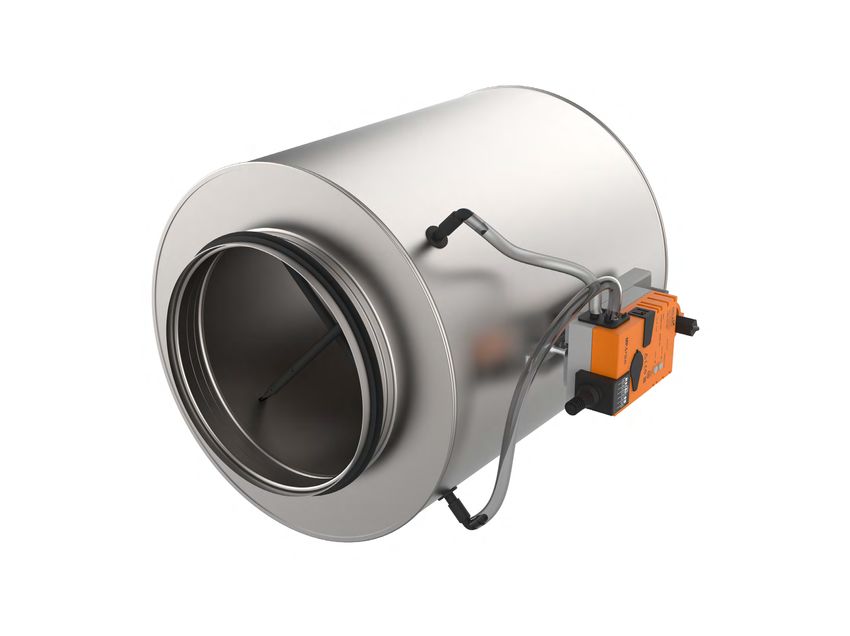
Product overview
Produktübersicht
Installation
Controllers
Steuerungen
Accessories
Zubehör
Parametrization
Parametrisierug
Diagrams
Diagramme
Maintenance
Wartung
PRODUCT OVERVIEW
PRODUCT OVERVIEW
PRODUKTÜBERSICHT AIRFLOW REGULATION
LUFTSTROMREGELUNG
PRÜFUNGEN
TESTS AND UND
CERTIFICATES
ZERTIFIKATE
Alleour
All unsere
dampers
VVS-areRegler
submitted
werdento avon
number
offiziellen
of tests
Prüfinstituten
by official Weitere
For moreInformationen
information about
über certificates,
Zertifikate finden
visit ourSie
website:
auf unserer
test institutes.
einer Reihe von Reports
Tests ofunterzogen.
these tests Die
formBerichte
the basisüber
for the
diese Website:
approvals ofbilden
Prüfungen our dampers.
die Grundlage
Klimaoprema
für die VAV
Zulassungen
dampers unserer
are www.klimaoprema.com/rvp-c
www.klimaoprema.com/rvp-c
also suitable
VVS- Regler.for
Klimaoprema
installation inVVS-
buildings
Regler
withsind
high auch
hygienic
für den
demands
Einbau in such
Gebäuden
as hospitals,
mit hohen
clinics
hygienischen
and pharmaceutical
Anforderungen
areas.
wie Krankenhäuser, Kliniken und pharmazeutische Bereiche
To confirm this, out products are tested by an independent
geeignet. Einbauerklärung:
Declaration of incorporation:
Institute of Hygiene, based in Gelsenkirchen, Ruhr, and comply
with dies
Um directives
zu bestätigen,
and guidelines
werden
in VDI
unsere
6022.Produkte von einem www.klimaoprema.com/rvp-c/doi
unabhängigen Hygieneinstitut mit Sitz in Gelsenkirchen, Ruhr,
geprüft und entsprechen den Richtlinien und Vorgaben der VDI
6022.
3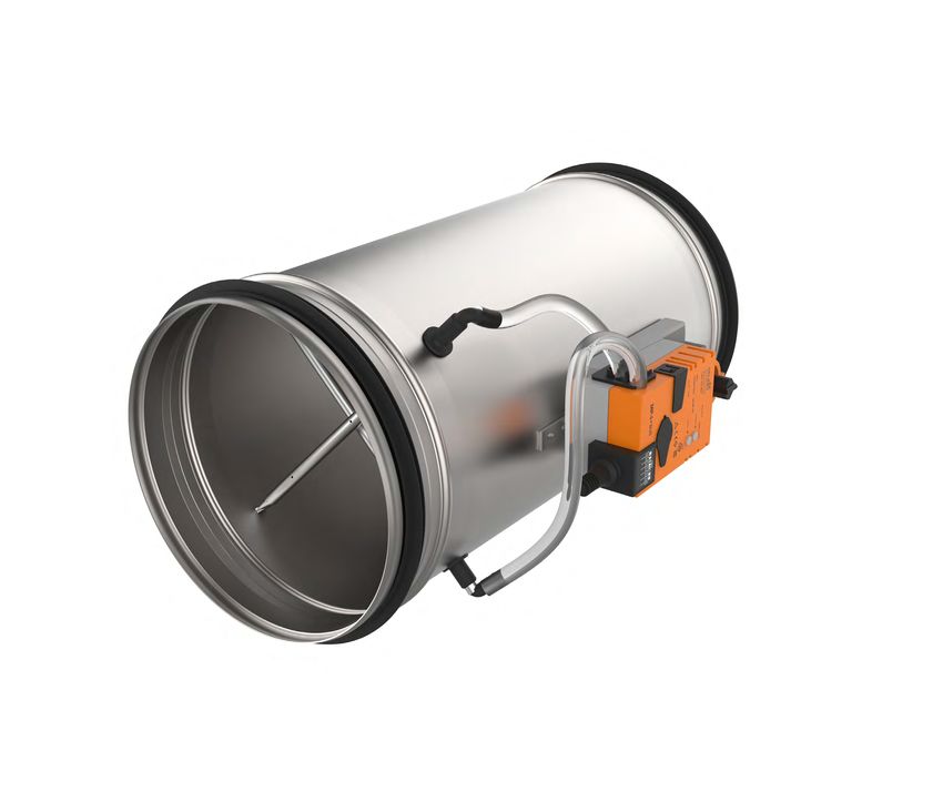
1
2 3
4 5
6
TECHNICAL DATEN
TECHNISCHE DATA 7
Product overview
Produktübersicht
Das
VAV Gehäuse
damper der VVS-isRegler
casing wird aus verzinktem
manufactured from 8
Stahlblech hergestellt, kann aber auf Wunsch auch Installation
galvanized steel sheet, but on demand can be
aus:
produced out of:
• verzinktem Stahl und pulverbeschichtet Controllers
Steuerungen
Edelstahl EN 1.4301/EN 1.4404 (AISI
• Galvanized
304/316L) steel and powder coated 9 Accessories
Zubehör
• Stainless steel
Edelstahl EN EN 1.4301/EN
1.4301/EN 1.4404 (AISI
1.4404 (AISI
304/316L)
304/316L) und pulverbeschichtet 10
• VVS- Regler für explosionsgefährdete Bereiche
Parametrization
Parametrisierug
Stainless steel EN 1.4301/ 11
sind ebenfalls erhältlich!
EN 1.4404 (AISI 304/316L) and 13
Diagrams
Diagramme
powder coated 12
Maintenance
Wartung
VAV damper for areas with potentially
explosive atmospheres are also available!
14
PRODUCT OVERVIEW
PRODUKTÜBERSICHT AIRFLOW REGULATION
LUFTSTROMREGELUNG
Product label
Produktetikett Product specifications
Produktspezifikationen
1 - Infos
Company zum Unternehmen
info Nominal sizesRVP-C
Nenngrößen RVP-C ød100 - 630 [mm]
2 - Seriennummer
Serial number
Casing length
Gehäuselänge 400 - 850 mm
3 - Produktionsdatum
Production date
Temperature range
Temperaturbereich 0 °C ... 50 °C
4 - Typ
Type
5 - Arbeitsblatt
Worksheet Volume flow rate range
Volumenstrombereich up to
bis zu12482
12482m³/h
m³/h
6 - Kunde
Customer Differential pressure range
Differenzdruckbereich up to
bis zu1000
1000Pa
Pa
7 –- Installation
Installationsort
location
8 - Parametrisierug
Parametrization Casing air leakage
Gehäuse-Luftleckage Class C, EN 1751
9 - Antrieb
Actuator Geschlossene Klappenblatt
Closed blade air leakage Class
Class 3,
3, EN
EN 1751
1751
10 --Control
Steuersignal
signal Luftleckage
11 - Regelungstyp
Regulation type Upstream velocity < 12 m/s
Anströmgeschwindigkeit < 12 m/s
12 - Luftstromrichtung
Air flow direction EC conformity EN ISO 12100:2010
EC-Konformität EN ISO 12100:2010
13 - Benutzerhandbuch
User manual link Link
Declaration of
14 - Barcode Einbauerklärung für Doi 419/2020_03
incorporation Doi 419/2020_03
unvollständige Maschinen
4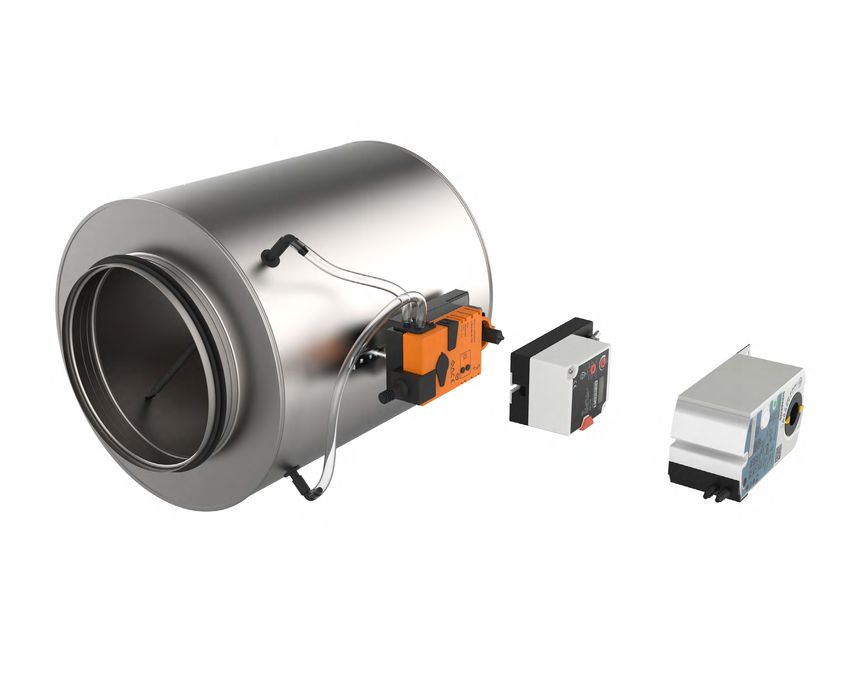
MODELS
MODELLE
VVS-dampers
VAV Regler mit
with
kompakten
compact
controllers
Reglern
Diese Regler
These regulators
sind are
mit equipped
kompaktenwith VAV-Reglern
compact Product overview
Produktübersicht
VAV controllers
ausgestattet, diewhich
Antrieb,
include
Regleractuator,
und Staudruck-
control-
ler and in
sensor dynamic
einem pressure
Gerät vereinen.
sensor inVAV-Regler
the same Installation
device. als druckunabhängig bezeichnet, wenn
werden
VAV units
der Luftdurchsatz
are called unabhängig
pressure independent
von den when Vari- Controllers
Steuerungen
the air flow
ationen desrate
Versorgungsdrucks
passing through it konstant
is maintained
ge-
constant
halten wird.
regardless
Dieser Regelungsgrad
of variations in thewirdsystem
durch Accessories
Zubehör
supply
den Zusatz
pressure.
eines This
Luftstromsensors
level of control(Messkreuz)
is possible
with eines
und the addition
variablenofLuftreglers
airflow sensor
erreicht,
(measuring
der den Parametrization
Parametrisierug
cross) and variable
Luftstrom entsprechend
air controller
dem that gewünschten
maintains
the airflowaufrechterhält.
Sollwert according to required
Der Reglerset-point.
misst den
The Diagrams
Diagramme
controller is
Luftstrom durch
measuring
das Gerät
the airflow
und moduliert
through den
the
device and modulates
Klappenwinkel als Reaktion
the damper
auf Änderungen-
blade angle Maintenance
Wartung
in response
im System. to Das
system
voreingestellte
disturbances.
Volumen
The preset
kann
volume cankalibrierten
zwischen be varied between
Luftstromgrenzen
calibrated airflow
(Vmin,
limits (Vmin,
Vmax) über Vmax)
ein Eingangssteuersignal
via input control signal (analog,
(ana-
log, communication protocol)
Kommunikationsprotokoll) variiert
provided
werden,
by room
das
thermostat
von einem or Raumthermostat
HVAC BMS system. oder einem HLK-
BMS-System bereitgestellt wird.
PRODUCT OVERVIEW
PRODUKTÜBERSICHT AIRFLOW REGULATION
LUFTSTROMREGELUNG
Steuerungen
Die druckunabhängige
Pressure
Verteilung
distributiondes
Regelung sorgt
independent regulation
Luftvolumens
of air volume to the
ensuresfür economical
aufventilated
Controllers
eine wirtschaftliche
die zu belüftenden
spaces ac- Räume,
Analoge Kommunikation
Kompakte VAV-Regler, die über ein analoges 0(2)..10V-Signal gesteuert
ORDERING KEY RVP-CRVP-C
BESTELLSCHLÜSSEL
Analoguewerden.
communication
Alle Regler sind mit einem Rückmeldesignal für gängige
entsprechend
cording to the den individuellen
individual Raumanforderungen.
space requirements. A wide Für die (3) Communication
CompactFunktionen
VAV controllers controled
wie aktueller via 0(2)..10V
Volumenstrom, analogue
Druckabfall oder Klappenwinkel (1) Modell
(1) Model (2)(2)Abmessungen
Dimensions (3) Kommunikation typ (4) Isolierung
Insulation
VAV-Klappen steht are
range of actuators eineavailable
breite Auswahl
with VAVan Antrieben zur Verfü-
dampers type
signal. Allausgestattet.
controllers are equipped with feedback signal for
gung (Belimo,
(Belimo, Gruner Gruner
and und Siemens),
Siemens), and die eine Vielzahl
a wide range of von Kom-
common functions like actual flow, pressure drop or damper
munikationsprotokollen
communication protocols unterstützen
are supported (MP-Bus,
by them KNX,
(MP-ModBus, MP-Bus-Kommunikation
blade angle. RVP-C - øD - MP - Z
Bacnet).
Bus, KNX, ModBus, Bacnet). MP-Bus ist ein einfacher Sensor-/Aktor-Bus, der verwendet wird für
MP-Bus bestimmte
communication Subsysteme von Gebäudeautomationssystemen. MP-Bus
Dynamische
Dynamic pressure Drucksensoren
sensors have habenoperating
einen Arbeitsbereich
range MP-Bus is a simpleeine
verwendet sensor/actuator bus, which is used
Master/Slave-Bus-Technologie, beifor
der eine bestimmte
0..600Pa, mitwith±1Pa
±1PaAuflösung.
resolution. certain sub-systems of building automation systems. MP-Bus
Anzahl von Slave-Geräten an ein MP-Master-Gerät angeschlossen (1) RVP-C - Runder
Cylindrical
VVS-Regler
VAV damper KNX-S - Siemens KNX
Der maximale
Maximum Betriebsdruck
operating im Kanal
duct pressure beträgt 1000Pa.Dasuses
is 1000Pa. Ge-a master/slave
werden kann. bus technology where defined number of KNX - Belimo KNX
häuse
Casingkann zusätzlich
can also mit 50 mm
be additionally Mineralwolle
insulated in einem
with 50mm slave
of doppel- units can be connected to an MP-Master unit. (2) øD - Nenndurchmesser
Nominal diameter BAC - Siemens Bacnet
Kommunikationsprotokolle
wandigen
mineral wool verzinkten
and doubleBlechgehäuse isoliertsheet
skin galvanized werden, um den
casing Communication
Ab- protocols sind auch mit Unterstützung für die meisten gängigen
Die Kompaktregler PP - Gruner analogue (0..10V)
strahlungsschall
for reduction of thedes casing
Gehäuses zu reduzieren.
radiated noise. TheDas CompactKommunikationsprotokolle
Klappenblatt
damp- controllers are also available with support
erhältlich: for most
ModBus, Bacnet und KNX. (3) Kommunikation typ:
Communication type:
und die Anschlussstutzen
er blade and the connection sind mit Gummidichtungen
sleeves are equipped with common Kommunikationsprotokolle
versehen. communication protocols: ModBus, Bacnet and KNX. einer größeren
ermöglichen den Anschluss MP - Belimo MP (4) Z - 50 mm Isolierung
mineral wool
mit
Die
rubberKlappen sindATEX
gaskets. auch rated
in ATEX-Ausführung erhältlich
version is available and und Communication
mit protocols
Anzahl von Geräten enable
an ein connection
gemeinsames of Kommunikationsnetzwerk.
much larger Das MF - Belimo analogue (0..10V) Mineralwolle
insulation
Schischek-Antrieben
equipped with EX rated undSchischek
-Reglern inactuators
EX-Ausführung
and con- number ofNetzwerk
ausgestat- units to awird
common communication network.
von einem Gebäudemanagementsystem Network (BMS) gesteuert. SGB - Siemens analogue (0..10V)
tet.
trollers. is controled by a building management system (BMS) controller. MOD-S - Siemens Modbus
Schischek EX
Schischek EX MOD-BAC - Belimo Modbus / Bacnet
VAV-Klappen mit ATEX-Zulassung sind mit Schischek ExMax-Antrieben
ATEX rated VAV dampers are equipped with Schischek ExMax MOD-G -Gruner Modbus
und ExReg Volumenstrom-/Druckreglern ausgestattet. Optional kann
actuatorsdasandGehäuse
ExReg volumetric/pressure controllers. Optionally,
in Edelstahl EN 1.4301/EN 1.4404 (AISI 304/316L) gefertigt
casing can be produced in EN 1.4301/EN 1.4404
werden.
(AISI 304/316L) stainless steel.
5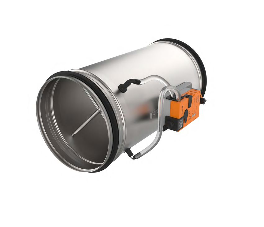
RVP-C                                                                                                     Product overview
                                                                                                          Produktübersicht
withBelimo-Regelung
mit  Belimo controller                                                                                    Installation
Regelung
Volume   flow
            descontrol
                Volumenstroms
                       regulation nach
                                  by a given
set-point.
einem   bestimmten
            Factory parametrization
                     Sollwert. Werkseitige
                                     in accordance
                                                                                                          Controllers
                                                                                                          Steuerungen
with clients request.
Parametrierung    nach Kundenwunsch.
                                                                                                          Accessories
                                                                                                          Zubehör
•   Hoheregulation
    High    Regelgenauigkeit.
                      precision.
•   No maintainance
    Keine   Wartung erforderlich
                        required.
                                                                                                          Parametrization
                                                                                                          Parametrisierug
•   Airtightness classes according
    Luftdichtheitsklassen   nach ENto EN
                                      1751,
                                         1751,
                                             C 3C 3
•   Hygiene certificate
    Hygienezertifikat  nach
                          according
                             VDI 6022.
                                     to VDI 6022.
                                                                                                          Diagrams
                                                                                                          Diagramme

                                                                                                          Maintenance
                                                                                                          Wartung
OPTIONS

           PRODUCT OVERVIEW
           PRODUKTÜBERSICHT                                                                            AIRFLOW REGULATION
                                                                                                       LUFTSTROMREGELUNG

OPTIONEN                                                 RVP-C                   RVP-C-Z                     L
Constant, variable, 3-stage control                                              (Isoliertes
                                                                                 (Insulated Gehäuse)
                                                                                             casing)
Single, master-slave
Konstante,   variable, 3-stufige
                       and parallel
                                 Regelung
                                    modes of operation                                                      Lz
InsulatedMaster-Slave-
Einzel-,   casing (50 mm)und Parallelbetrieb,
Isoliertes Gehäuse (50 mm)                                            L
MP - Belimo MP
MF - Belimo analogue (0..10V)
                                                                 60
                                                                 60

     - Belimo- MP
MOD-BAC
MP             Belimo Modbus / Bacnet
KNX-B
MF   - Belimo
         - Belimo
               analogue
                   KNX (0..10V)
MOD-BAC - Belimo Modbus / Bacnet
KNX-B - Belimo KNX
                                                                          Dn-2

                                                                                                                             Dz-2
                                                                                                                             Dz-2
                                                                                                                                    6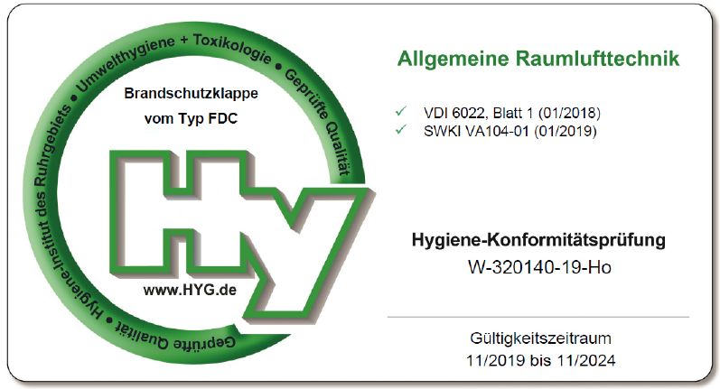
RVP-C                                                                                                      Product overview
                                                                                                           Produktübersicht
withGruner-Regelung
mit  Gruner controller                                                                                     Installation
Regelung
Volume   flow
            descontrol
                Volumenstroms
                       regulation nach
                                  by a given
set-point.
einem   bestimmten
            Factory parametrization
                     Sollwert. Werkseitige
                                     in accordance
                                                                                                           Controllers
                                                                                                           Steuerungen
with clients request.
Parametrierung    nach Kundenwunsch.
                                                                                                           Accessories
                                                                                                           Zubehör
•   Hoheregulation
    High    Regelgenauigkeit.
                      precision.
•   No maintainance
    Keine   Wartung erforderlich
                        required.
                                                                                                           Parametrization
                                                                                                           Parametrisierug
•   Airtightness classes according
    Luftdichtheitsklassen   nach ENto EN
                                      1751,
                                         1751,
                                             CC33
•   Hygiene certificate
    Hygienezertifikat  nach
                          according
                             VDI 6022to VDI 6022.
                                                                                                           Diagrams
                                                                                                           Diagramme

                                                                                                           Maintenance
                                                                                                           Wartung

           PRODUCT OVERVIEW
           PRODUKTÜBERSICHT                                                                             AIRFLOW REGULATION
                                                                                                        LUFTSTROMREGELUNG

OPTIONS
OPTIONEN                                                  RVP-C                   RVP-C-Z                     L
                                                                                  (Isoliertes
                                                                                  (Insulated Gehäuse)
                                                                                              casing)
Konstante,variable,
Constant,    variable,3-stage
                       3-stufige
                               control
                                 Regelung                                                                    Lz
Single, master-slave
Einzel-, Master-Slave-andundparallel
                              Parallelbetrieb,
                                     modes of operation
Insulated Gehäuse
Isoliertes casing (50(50
                       mm)
                         mm)                                           L

PP - Gruner analogue (0..10V)
                                                                  66
                                                                  60

MOD-G -Gruner Modbus

                                                                           Dn-2

                                                                                                                              Dz-2
                                                                                                                                     7
RVP-C Product overview
Produktübersicht
withSiemens-Regelung
mit Siemens controller Installation
Regelung
Volume flow
descontrol
Volumenstroms
regulation nach
by a given
set-point.
einem bestimmten
Factory parametrization
Sollwert. Werkseitige
in accordance
Controllers
Steuerungen
with clients request.
Parametrierung nach Kundenwunsch.
Accessories
Zubehör
• Hoheregulation
High Regelgenauigkeit.
precision.
• No maintainance
Keine Wartung erforderlich
required.
Parametrization
Parametrisierug
• Airtightness classes according
Luftdichtheitsklassen nach ENto EN
1751,
1751,
C 3C 3
• Hygiene certificate
Hygienezertifikat nach
according
VDI 6022to VDI 6022.
Diagrams
Diagramme
Maintenance
Wartung
PRODUCT OVERVIEW
PRODUKTÜBERSICHT AIRFLOW REGULATION
LUFTSTROMREGELUNG
OPTIONS
OPTIONEN RVP-C RVP-C-Z L
(Isoliertes
(Insulated Gehäuse)
casing)
Konstante,variable,
Constant, variable,3-stage
3-stufige
control
Regelung Lz
Single, master-slave
Einzel-, Master-Slave-andundparallel
Parallelbetrieb,
modes of operation
Insulated Gehäuse
Isoliertes casing (50(50
mm)
mm) L
KNX-S - Siemens KNX
66
60
BAC - Siemens Bacnet
SGB - Siemens analogue (0..10V)
MOD-S - Siemens Modbus Dn-2
Dz-2
8RVP-C-EX
Regelung des Volumenstroms nach
einem bestimmten Sollwert. Werkseitige
RVP-C-EX
Parametrierung nach Kundenwunsch.
• Hohe Regelgenauigkeit. Product overview
Produktübersicht
•VolumeKeine Wartung
flow controlerforderlich
regulation by a given
•set-point.
DKonzipiert fürparametrization
alle Gase, Nebel Installation
Factory in und in
accor-
den Zonen 1 und 2, mit elektronischer
dance with clients request High regulation
Steuerung zusätzlich fürrequired
Stäube in den Controllers
Steuerungen
precision.No maintainance
Zonen 21 und 22
• Geschlossene
Designed for allLamellen-Leckage nach EN
gases, mists and vapours 1 2 Accessories
Zubehör
1751, bis zu Klasse 4
in zones 1 and 2, with electronic control
• Gehäuse-Leckluftstrom gemäß21EN 1751, Schischek ExMax ExReg-V VAV Regler Parametrization
Parametrisierug
additionally for dusts in zones and 22
Klasse C Federrücklaufantriebe
• Closed blade air leakage to EN 1751, Diagrams
Diagramme
up to class 4
•Für weitere
Casing air leakage to EN 1751, class C
Informationen: Maintenance
Wartung
(1) Schischek ExMax Antriebe
For more details:
(2) ExReg-V VAV Regler
(1) Schischek ExMax actuators
(2) ExReg-V VAV controllers
PRODUCT OVERVIEW
PRODUKTÜBERSICHT AIRFLOW REGULATION
LUFTSTROMREGELUNG
ORDERING KEY RVP-C-EX
BESTELLSCHLÜSSEL RVP-C-EX
(2)(2)Stellantrieb/
Actuator/
BESCHREIBUNG
DESCRIPTION (1) Model (3)(3)Abmessungen
Dimensions (4) Isolierung
Insulation
Controller
controller
VVS-Regler
VAV units forfür explosionsgefährdete
potentialy Bereiche werden
explosiosive atmospheres mit Schischek
are equipped ExMax-Federrücklaufantrieben
with Schischek ExMax spring return
(1)
actuators (1) and ExReg-V VAV controllers (2). ExReg-V controllers can be ohne
und ExReg-V VVS-Regler (2) ausgerüstet. Die ExReg-V-Regler können elektronische
parametered on-siteHilfsmittel
using
vor Ort mittels Menüführung parametriert werden. Die interne PID-Regelstruktur ist einfach
menu navigation, without any electronic aids. The internal PID control structure is easy to use and zu bedienen
can RVP-C - EX - øD - Z
und kann für Standardanwendungen
be configured vollautomatisch
fully automatically for standard konfiguriert
applications. werden.
The display Das Display
indicated zeigt während
the current status for
des Betriebs
actual den aktuellen
value, setpoint value Status für Istwert,
and control Sollwert
variable duringund Stellgröße an.
operation.
(1) RVP-C - runder
Cylindrical
VVS-Regler
VAV damper (3) øD - Nenndurchmesser
Nominal diameter
Nummer der Baumusterprüfbescheinigung:
Type Examination Certificate Number: FIDIFIDI2121 ATEXD060.
ATEX D060. Equipment
Das Gerät entspricht
compliesden
withgrundlegenden
the essential
Sicherheits- und Gesundheitsanforderungen für die Konzeption und den Bau von Geräten
health and safety requirements relating to the design and construction of equipment intended zur Verwendung
to use in (2) EX - Schischek ExMax + ExReg-V
in explosionsgefährdeten
potentially Bereichen
explosive atmospheres gemäß
given Anhang
in annex VIIIVIII der directive
of the RichtlinieATEX
ATEX2014/34/EU.
2014/34/EU. EX-F - Schischek ExMax mit
withFederrücklauf
spring return + ExReg-V (4) Z - 50 mm Isolierung
mineral wool
mit
Mineralwolle
insulation
MATERIALIEN
MATERIALS
Gehäuse
Casing andund Klappenblatt
damper blade ofder
theVVS-Regler
VAV damper sind
areaus verzinktem
produced out Stahlblech gefertigt.
of galvanized Die Dichtungen
steel sheet. Sealing CLASSIFICATION ATEX
KLASSIFIZIERUNG RATED VAV ACTUATORS
ATEX-BEWERTETE VAV-ANTRIEBE
werden
gaskets aus EPDM-Gummi
are produced out ofhergestellt,
EPDM rubber,und das
and Messkreuz wird aus
measuring cross Aluminiumrohren
is made gefertigt.
out of aluminium AufOn
tubes. be-
sonderen WunschVAV
special demand,
hergestellt
kann das VAV-Gehäuse
casing can be producedaus out
Edelstahlblech
of stainless EN
steel1.4301/EN 1.4404 (AISI1.4404
sheet EN 1.4301/EN 304/316L)
(AISI II 2G Ex h IIC T6 Gb
304/316L),werden
and canund
alsokann auch in jeder Standard
be powdercoated RAL-Farbe
to any standard RALpulverbeschichtet
chart colour. werden.
II 2D Ex h IIIC T80°C Db
Weitere
For moreInformationen
informationzurabout
Ex-Klassifizierung
Ex classification,
finden visit
Sie
website:
auf der Website:
ATEX classification
ATEX classification
9Kompakte
Compact VAV
VAV-Lösungen
solutions
Siemens GL(D)B181.1E/MO
Siemens GL(D)B181.1E/KN
Siemens GL(D)B181.1E/BA
Gruner 227VM-024-05(10)
Siemens GL(D)B181.1E/3
Belimo L(N)MV-D3-MOD
Belimo L(N)MV-D3-KNX
Belimo L(N)MV-D3-MP
Belimo L(N)MV-D3-MF
Product overview
Produktübersicht
Anwendungen
Applications
VAV/CAV-Regelung
VAV/CAV control • • • • • • • • • Installation
Stellantriebe
Actuators
Controllers
Steuerungen
Drehmoment
Torque 5(10) Nm 5(10) Nm 5(10) Nm 5(10) Nm 5(10) Nm 5(10) Nm 5(10) Nm 5(10) Nm 5(10) Nm
Running
Laufzeit
time Variable Variable Variable Variable Variable Variable Variable Variable Variable Accessories
Zubehör
Steuerung
Control
Parametrization
Parametrisierug
0/2..10V • • • •
Über
Via contacts
Kontakte(CAV)
(CAV) • • • Diagrams
Diagramme
MP-Bus •
Maintenance
Wartung
Modbus RTU • •
KNX • •
Bacnet •
PP Bus •
Pressure
Drucksensor
sensor
0..450Pa 0..450Pa 0..450Pa 0..450Pa 0..300Pa 0..300Pa 0..300Pa 0..300Pa 0..250Pa
Accessories
Zubehör
KOER Codis E35-VAV • • • • • LUFTSTROMREGELUNG
AIRFLOW
PRODUCTREGULATION
OVERVIEW
PRODUKTÜBERSICHT
Room
Raumtemperatur-Regler
temperature controler/ CR24
/ CR24.. • •
Fan-Optimierer
Fan optimiser //COU24-A-MP
COU24-A-MP • •
MP gateways / UK24xxx • •
PC Tool / MFT-P • • • •
Service-Werkzeug
Service tool / ZTH-GEN
/ ZTH-GEN • • • •
Siemens software ASC941 • • • •
AST20 • • • •
Versorgung
Supply //Inputs
Eingänge
AC/DC 24V • • • • • • • • •
Luftstrom
Airflow / Luftstrom
Airflow /
Modbus Modbus Bacnet
Bacnet/
/ Damper
Klappen- / Damper
Klappen- KNX/
KNX Nicht
/Not KNX/
KNX Nicht
/Not
Rückmeldesignall
Feedback signal //Nicht
Not Luftstrom
Airflow //Nicht
Not Not
/ Nicht
rele- Luftstrom
Airflow
position position relevant relevant
relevant relevant relevant
vant
/ ∆p / ∆p
*if not otherwise
*wenn nicht anders
specified,
angegeben,
regulator
wird isder
setRegler
to standard
auf diefactory
werkseitigen
values Standardwerte
Vmax and Vmin. Vmax und Vmin eingestellt.
10VAV Universal
universal Komponenten
components
A
A VOLUMENSTROMREGELUNG
VOLUMETRIC FLOW CONTROL
Standard VAV casing equipped
Standard-VAV-Gehäuse mit VRU-D3-
with VRU-D3-
BAC-
BAC controler/pressure
Regler/Drucksensor undsensor
modulierendem,
and standard
modulating, fast-acting
schnellwirkendem oder or
federrückstellendem
spring return
actuator. Casing is
Standardantrieb. Das
equipped
Gehäuse with
ist measuring
mit einem
cross for airflow
Messkreuz zur Messung
measurement
und Regelung
and controldesin
the duct. im Kanal ausgestattet.
Luftstroms Product overview
Produktübersicht
Installation
B KANALDRUCKREGELUNG
DUCT PRESSURE CONTROL
D Klappengehäuse
Damper ohnemeasuring
casing without Messkreuz, ausges-
cross, B
Controllers
Steuerungen
tattet mit with
equipped Kanaldruckregler
duct pressureund statischem
controler and
Sensor VRU-M1-BAC.
static sensor Die statische
VRU-M1-BAC. Druck-
Static pressure Accessories
Zubehör
sonde
probe isistinstalled
am Kanalonangebracht, und
the duct, and der sta-
static
tische
pressureDruck wird im Kanal
is maintained aufrechterhalten.
inside the duct. Parametrization
Parametrisierug
RAUMDRUCK REGELUNG Diagrams
Diagramme
C ROOM PRESSURE
Klappengehäuse ohneCONTROL
Messkreuz, ausges-
Damper
tattet mitcasing without measuring
Kanaldruckregler cross,
und statischem Maintenance
Wartung
equipped
Sensor with duct pressure
VRU-M1R-BAC. controler
Statische Drucksonde
andimstatic
ist Raum sensor
und im VRU-M1R-BAC.
Referenzbereich Static
installiert.
pressure
Im Raum probe is installed
wird ein statischerinÜber-
the room
oderand
Unter-
in the reference
druck area. Static overpressure or
aufrechterhalten. C
underpressure is maintained in the room.
PRODUKTÜBERSICHT
PRODUCT OVERVIEW AIRFLOW REGULATION
LUFTSTROMREGELUNG
VARIANTEN
VARIANTS
VAV-Universal-Komponenten BESTELLSCHLÜSSEL
ORDERING KEY
RVP-C
RVP-C
VAV-Komponenten bieten eine modulare Produktpalette Es stehen drei verschiedene Sensor- und Controllertypen (1) Variable
VAV universal components zur Verfügung: (1) Variable (2) Casing (3)(3) (4) Actuator
(4) Typ des (5)Controller
(5) Typ des
für die Volumen- oder Druckregelung in Kanälen oder air volume (2) Gehäusetyp (6) Isolierung
Insulation
VAV components offer modular product range capable Three different sensor and controller types are available: Luftmengenklappe type Abmessungen
Dimensions Stellantriebs
type Reglers
type
Räumen. • VRU-D3-BAC - Kanaldruck-/Volumenstromregler mit damper
of volumetric or pressure control in duct or rooms. • dynamischer
VRU-D3-BACDrucksensor
- duct pressure/volume
D3 controller with
Es gibt zwei Typen von Sensoren, den dynamischen RVP-C
RVP-C - - WAWA - - øD
øD - M - D3 - Z
Two types of
D3-Sensor sensors
und are available,
den statischen D3 dynamic sensor
M1-Membran- dynamic D3 pressure sensor
• VRU-M1-BAC - Kanaldruck-/Volumenstromregler mit (1) RVP-C
(1) RVP-C (4) M - Standard
standard VAV
VAV actuator
Antrieb
and M1 diaphragm
Drucksensor. static pressure
Der D3-Sensor wird in sensor.
wirklich D3 sensor
• VRU-M1-BAC - duct pressure/volume
statischem Drucksensor controller with M1
M1 für Kanaldruckregelung MQ - Schnell
fast acting
wirkender
VAV actuator
VAV-Antrieb
is used inLüftungssystemen
sauberen realtively clean ventilation
verwendet,systems whereas
während der
diaphragm sensorfürisAbluftsysteme
Membransensor used for pulluted
verwendet
air systems.
wird. static pressure sensor for duct pressure control (2) WA -(2)
standard
WA - standard
VAV Gehäuse
VAV casing F - Federrücklauf
spring return VAV
VAV-Antrieb
actuator
• VRU-M1R-BAC - Druckregler mit statischem Drucksensor
• M1VRU-M1R-BAC - pressure controller with M1 static
zur Raumdruckregelung WMC - Gehäuse
WMC - casing
ohne Messkreuz
without measuring cross
Multiple
Es stehencasing
daheroptions
mehrereareGehäuseoptionen
therefore avilablezur
to provide (5)
pressure sensor for room pressure control MC - Gehäuse
MC - only
nur mit
measuring
Messkreuz
cross D3 - Staudruckregler
dynamic pressure controller
a basis for components
Verfügung, um eine Basisand
füractuators.
Komponenten und Es gibt verschiedene Typen von Aktuatoren:
Aktoren zu schaffen..Es gibt drei Typen von Gehäusen, M1- Statischer
static duct Kanaldruckregler
pressure controller
There are three types of casings that can be ordered: There types of actuators are available: (3) (3)
die bestellt werden können:: • Standard-Regelantrieb øD - Nenndurchmesser
øD - nominal diameter M1R - Statischer
static roomRaumdruckregler
pressure controller
• WA - RVP casing with measuring cross and •• Standard modulating
Schnell wirkender actuator
Regelantrieb
• WA - RVP Gehäuse mit Messkreuz und (6) Z - 50 mm Isolierung
mineral wool
auscasing
Mineralwolle
insulation
damper blade without actuator
Klappenblatt ohne Stellantrieb •• Fast acting modulating
Regelantrieb actuator
mit Federrücklauf
• WMC - RVP casing without measuring cross and
• WMC - RVP Gehäuse ohne Messkreuz und • Spring return modulating actuator
actuator but with damper blade
Stellantrieb, aber mit Klappenblatt Integrierte NFC-Schnittstelle zur einfachen Inbetriebnahme und
• MC - measuring cross only Konfiguration
Integrated NFC mitinterface
einem Smartphone über die Belimo
for simple commissioning Assistant
and
• MC - Gehäuse nur mit Messkreuz
App
configuration with a smartphone using the Belimo Assistant
App
11Druck
Pressure
VAV-Systemkomponenten
VAV system components
Komponente
Component Beschreibung
Description Documentation
Dokumentation
VRU-D3-BAC Modbus RTU, Bacnet MS/TP, MP-Bus, Staudrucksensor
dynamic pressure0....500Pa
sensor 0....500Pa technisches
TechnicalDatenblatt
sheet
VVolumenstrom-Anwendungen
Volume flow applications
VRU-M1-BAC Modbus RTU, Bacnet MS/TP, MP-BUS, Statik-Sensor
static sensor 0....600Pa
0....600Pa
technisches
TechnicalDatenblatt
sheet
Kanaldruck-Anwendungen
Duct pressure applications
VRU-M1R-BAC Modbus RTU, Bacnet MS/TP, MP-BUS, Statik-Sensor
static sensor -75...+75Pa
-75...+75Pa technisches
TechnicalDatenblatt
sheet
Raumdruck-Anwendungen
Room pressure applications
VAV-Universal, ready-to-connect
VAV-Universeller, anschlussfertigerdamper actuatorfür
Klappenantrieb forVAV-
VAV and
und CAV units in in
CAV-Boxen technical building
der technischen
installations
Gebäudeausrüstung
LM24A-VST Torque motor 5 Nm 5 Nm
• Motor-Drehmoment TechnicalDatenblatt
technisches sheet Product overview
Produktübersicht
Nominal voltageAC/DC
• Nennspannung AC/DC24 24VV
Control communicative
• Kontrolle kommunikativ PP Installation
VAV-Universal, ready-to-connect
VAV-Universeller, anschlussfertigerdamper actuatorfür
Klappenantrieb forVAV-
VAV and
und CAV units in in
CAV-Boxen technical building
der technischen
installations
Gebäudeausrüstung
NM24A-VST Torque motor 10 Nm10 Nm
• Motor-Drehmoment TechnicalDatenblatt
technisches sheet Controllers
Steuerungen
Nominal voltageAC/DC
• Nennspannung AC/DC24 24VV
Control communicative
• Kontrolle kommunikativ PP Accessories
Zubehör
VAV-Universal, ready-to-connect
VAV-Universeller, anschlussfertigerdamper actuatorfür
Klappenantrieb forVAV-
VAV and
und CAV units in in
CAV-Boxen technical building
der technischen
installations
Gebäudeausrüstung Parametrization
Parametrisierug
SM24A-VST • Motor-Drehmoment
Torque motor 20 Nm20 Nm TechnicalDatenblatt
technisches sheet
Nominal voltageAC/DC
• Nennspannung AC/DC24 24VV
• Kontrolle
Control communicative
kommunikativ PP
PP Diagrams
Diagramme
VAV-Universal, ready-to-connect
VAV-Universeller, anschlussfertigerdamper actuatorfür
Klappenantrieb forVAV-
VAV and
und CAV units in in
CAV-Boxen technical building
der technischen
installations
Gebäudeausrüstung Maintenance
Wartung
Torque motor 4 Nm 4 Nm
• Motor-Drehmoment TechnicalDatenblatt
sheet
LMQ24A-VST Nominal voltageAC/DC
AC/DC24 24VV technisches
• Nennspannung
Control communicative
• Kontrolle kommunikativ PP
RunningMotor
• Laufzeit time motor 2.5 s
2.5 s
VAV-Universal, ready-to-connect
VAV-Universeller, anschlussfertigerdamper actuatorfür
Klappenantrieb forVAV-
VAV and
und CAV units in in
CAV-Boxen technical building
der technischen
installations
Gebäudeausrüstung
Torque motor 8 Nm 8 Nm
• Motor-Drehmoment
NMQ24A-VST Nominal voltageAC/DC
AC/DC24 24VV TechnicalDatenblatt
technisches sheet
• Nennspannung
Control communicative
• Kontrolle kommunikativ PP
RunningMotor
• Laufzeit time motor 4 s
4 s
Anschlussfertiger
Ready-to-connectDrehantrieb Fail-Safe
rotary actuator für VAV-
fail-safe undand
for VAV CAV-Geräte
CAV unitsininder technischen
technical building
Gebäudeinstallation
installations Motor-Drehmoment 10 Nm LUFTSTROMREGELUNG
AIRFLOW
PRODUCTREGULATION
OVERVIEW
PRODUKTÜBERSICHT
NF24A-VST • Nennspannung
Torque motor 10AC/DC
Nm 24 V technisches Datenblatt
NF24A-VST • Kontrolle kommunikativ
Nominal voltage AC/DCPP 24 V Technical sheet
• Federrücklauf
Control communicative PP
• Spring return
Anschlussfertiger Drehantrieb Fail-Safe für VAV- und CAV-Geräte in der technischen
Gebäudeinstallation
Ready-to-connect rotary actuator fail-safe for VAV and CAV units in technical building
•installations
Motor-Drehmoment 20 Nm technisches Datenblatt
SF24A-VST • Nennspannung
Torque motor 20AC/DC
Nm 24 V
SF24A-VST • Kontrolle kommunikativ Technical sheet
Nominal voltage AC/DCPP 24 V
• Federrücklauf
Control communicative PP
• Spring return
Anschlussfertiger Stellantrieb mit Notstellfunktion für VAV- und CAV-Geräte in der technischen
Gebäudeinstallation
Ready-to-connect actuator with fail-safe for VAV and CAV units in technical building
NKQ24A-VST •installations
Motor-Drehmoment 6 Nm technisches Datenblatt
•• Torque
Nennspannung AC/DC 24 V
motor 6 Nm
NKQ24A-VST •• Nominal
Kontrollevoltage
kommunikativ Technical sheet
AC/DC PP 24 V
•• Control
Laufzeitcommunicative
Motor 4 s PP
• Running time motor 4 s
Anwendung
Application Sensor Kontrolle
Control Werkzeug
Tool
2…10 VV
duct pressure
PC-Tool
MS/TP
BelimoPC-Tool
BACnetMS/TP
pressure
0…10//2…10
RTU
zone
Komfortzone
ModbusRTU
Raumdruck
App
Sensortype
BelimoApp
Verschmutair
MP-Bus®
MP-Bus®
VAV/CAV
Luftkanal
VAV/CAV
EU
Modbus
Comfort
Polluted
ZTHEU
BACnet
Sensor
Belimo
Belimo
0…10
Room
ZTH
Air
D3, dynamic
VRU-D3-BAC • • - • - • • • • • • •
0...500 Pa
M1,
M1, diaphragm
Membran
VRU-M1-BAC • • - • • • • • • • • •
0...600 Pa
M1R,
M1R, diaphragm
Membran
VRU-M1R-BAC - - • • • • • • • • • •
-75...75 Pa
12Installation process
Montagehinweis
x Ød
n .1
mi Product overview
Produktübersicht
Installation
Controllers
Steuerungen
Accessories
Zubehör
Parametrization
Parametrisierug
d
2 xØ
n. Diagrams
Diagramme
mi Ød
x
.2 Maintenance
Wartung
in
m
RVP-C INSTALLATION
Alle installation
All Einbaulagen orientations
sind zulässigare (außer
permited bei Geräten
(except themit Die Standardkalibrierung
the factory. Standard calibration
impliziertimplies
Vnom-Werte,
Vnom values
die einer
thatLuft-
are Compact VAV mit
VAV-Antriebe actuators with integrated
integriertem dynamic pressure
Staudrucksensor sind für sen-
den low kleinen
mit volume Volumenströmen
airflow applications.aufTheDie control of the dampers
Ansteuerung der Klappen
units with the pressure control
Druckregelkomponenten). Die Genauigkeit
components).der TheVolu-
vol- equivalent to air duct velocity
kanalgeschwindigkeit von 12ofm/s 12 m/s.
entsprechen.
Vmax andDie Vmin
Werte
values
für sors areinintended
Einsatz for use inmit
Lüftungsanlagen ventialtion sysemsLuft
relativ sauberer withvorgeseh-
relatively it done über
erfolgt via analog signal (0(2)-10V)
ein analoges or someoder
Signal (0(2)-10V) of theüber
supported
eines der
ume control accuracy
menstromregelung hängt
depends
von ondenflow
Strömungsverhält-
conditions befor can beund
Vmax found
Vmin
in the
finden
table
Sieonin page
der Tabelle
2. auf Seite 2. clean
en. Dasair.bedeutet,
That means dassthat
diethe ventilation systems
Lüftungsanlagen keine should
abrasiven,not communication
unterstützten protocols. Most commonlyMeistens
Kommunikationsprotokolle. a BMS system
steuertisein
measuring
nissen vor dem
cross.Messkreuz
Bends, junctions
ab. B Rohrbogen,
and narrowingsAbzwei- or contain abrasive,
chemischen oder chemical
klebrigen or adhesive
Partikel particles.
enthalten Temperature
sollten. Der Tem- controlling thedie
BMS-System ventilation system (including
Lüftungsanlage the VAV’s),
(einschließlich but itaber
der VAVs),
widenings
gungen undof Verengungen
the duct cause oder
turbulence
Verbreiterungen
and maydes af- Der Vmin-Wert
Vmin value cankann
be calibrated
in einem Bereich
in a rangevonfrom
10%10% von Vnom
of Vnom.
ka- range in the place
peraturbereich am of installation is permited
Aufstellungsort to 0bis
ist auf 0 °C °C50 to °C
50 zuge-
°C. is possible
es for the
ist möglich, VAV’s
dass die to work
VAVs independently
unabhängig with a einfachen
mit einem simple
fect the measurement.
Luftkanals verursachenFor Turbulenzen
that reason, und
when
können
installing
die Vmax can
libriert werden.
be calibrated
Vmax kann in im
theBereich
range between
zwischenVminVminand
undVnom.
Vnom For regulation
lassen. Für diein Regelung
areas with incontaminated
Bereichen mit media, units with stat-
verunreinigten Me- room controller
Raumregler providing
arbeiten, it with
der ihnen denthe needed setpoint.
erforderlichen Sollwert vorgibt.
damper after
Messung beeinflussen.
a bend or Aus a T-section,
diesem Grund
it is neccessary
muss beim to Input signal
kalibriert werden.
regulates
Das the
Eingangssignal
volume flow regelt
between denVmin
Volumenstrom
and Vmax ic pressure
dien werdensensors
Geräte are used (VRU-M1-BAC
Kompakte mit statischen and VRU-M1R-
Drucksensoren
ensure long
Einbau der VAVenough
Reglerstraight
nach einem
sectionBogen
of the oder
duct.einem
Rec- linearily. Below
zwischen Vmin Vmin,
und Vmax
the volume
linear. flow
Unterhalb
cannotvonbe Vmin
regulated.
kann der BAC). These
eingesetzt controllers can
(VRU-M1-BAC undbe VRU-M1R-
calibrated toBAC).
regulate
Dieseairflow or
Regler Exceptimstand-alone
Außer operation,können
Stand-alone-Betrieb VAV’s VAV
can auch
work imin Parallelbetrieb
parallel
comendations
T-Stück ein ausreichend
for the length
langerof gerader
the straight
Abschnitt
sectiondes of Volumenstrom
It is possible to nicht geregelt
order werden. pre-calibrated
the dampers Es besteht die from
Möglich-
the pressurekalibriert
können in the duct or room.
werden, um den Luftstrom oder den Druck im operation
und and master/slave operation.
im Master/Slave-Betrieb arbeiten.InIm parallel operation sind
Parallelbetrieb
the duct:
Rohrs sichergestellt werden. Empfehlungen für die keit, die on
factory Regler werkseitig
a lower Vnomauf eine niedrigere
setting of 7 m/s. This
Vnom-Einstellung
consequent- Kanal oder im Raum zu regeln. control
die signals areimmer
Regelsignale allways the same,
gleich, andRegelparameter
und die control parameters Vmin/
Länge des geraden Abschnitts: ly lowers
von 7 m/sthe
vorzukalibrieren.
minimum airflow Dadurch
velocity
sinktthat
die can
minimal
be controlled
regelbare Control Vmin/Vmax
Vmax könnencanunabhängig
be set independently.
voneinander In eingestellt
master/slave werden. Im
• • Biegung
Bend - -1 1x xØØd
d (Vmin) to 0,7 m/s.
Luftstromgeschwindigkeit (Vmin) auf 0,7 m/s. Steuerung operation the actual signal
Master/Slave-Betrieb regeltfrom
dasthe master unit
Ist-Signal der isMaster-Einheit
controlling
Pressure independent VAV’s have the following control
• • T-Profil
T-section
- 2 x- Ød
2 x Ød Druckunabhängige VAV’s haben folgende Regelungs the reference
den air volume in the
Soll-Volumenstrom derslave unit.
Slave-Einheit. Die Stellantriebe
• • Dämpfer
Damper--22xxØd Ød IfWenn
the dampers
die Reglerare gemäß
installedden
according
Empfehlungen
to the recomendations,
installiert sind, parameters: Vmin
Parameter: Vmin (minimum
(minimaler airflow), Vmax (maximum
Luftstrom), airflow)
Vmax (maximaler Actuators
sind are overload
überlastsicher. proof. Compact,
Kompakt-, Standard- standard and high
und schnelllaufende
aiflow die
hängt control
Genauigkeit
accuracy derdepends
Luftstromregelung
on the airflow
von der
velocity
Luftstrom-
in the and Vnom (nominal airflow). These parameters
Luftstrom) und Vnom (Nennluftstrom). Diese Parameter are defining the speed actuators
Antriebe bleibenwillbei
remain at their last
Stromausfall in position in the event
ihrer letzten of
Stellung
Note:
Hinweis:
All duct
Alle Rohranschlüsse
fittings (eg. connections,
(z. B. Verbindungen,
branches Ab-
etc) duct.
geschwindigkeit im Kanal ab.. volume airflow range in which the VAV is
definieren den Volumenstrombereich, in dem der VAV operating. Nominal power shutdown.
stehen. Spring returnschließen
Federrücklaufantriebe actuatorsoderwill öffnen
completely close
die Klappe
zweigungen
should comply usw.)
withsollten der EN 1505 entsprechen.
EN 1505. • für Geschwindigkeiten > 3 m/s wird eine Genauigkeit von ± airflow rangewird.
betrieben depends Deron the size of the damper, and is equal
Nennvolumenstrombereich hängt or open the je
vollständig, damper, depending on their installation orientation.
nach Einbaulage.
Zur Wartung der VAV Regler sollten diese einfach aus- • 5% for velocities
angegeben > 3 m/s accuracy is declared to ± 5% von der Größe der Klappe abof 12
to the corresponding duct air velocity undm/s.entspricht der Die Parametrierung erfolgt werkseitig nach Kundenwunsch oder
gebaut werden
Installation spacekönnen. Derand
is requred Zugang
shouldinbeDoppeldeck-
reserved for • fürfor velocities
Geschwindigkeiten
between 1,2zwischen
m/s and1,23 m/s
m/s und
accuracy
3 m/siswird
de- entsprechenden Kanalluftgeschwindigkeit von 12 m/s. Parametrization is madeEntsprechend
Standardeinstellungen. in the factory according to the
können Änderungen der
en sollte über
installation andInspektionsöffnungen
maintainence of the VAV gwährleistet
dampers.sein.
It is clared
eine Genauigkeit
to ± 10% von ± 10% angegeben Vmin can
Vmin kannbe set
auf toeinen
any volume airflowVolumenstrom
beliebigen between 10%Vnom zwischen customer demands
Parametrierung vor or
Ortdefault
mit demsettings. Subequently
ZTH-Tool oder derchanges
Belimo
Standard RVP-C-Geräte
neccessary to provide acceswerdento ab.
the Werk vorkalibriert
inspection open- • fürfor Geschwindigkeiten
velocities < 1,2 m/sBelimo Motorantrieb
motor drive
• motor drives : :Belimo
Motorantriebe Belimo(MP,
(MP,ModBus/Bacnet,
ModBus/Bacnet,MF,
MF,KNX)
KNX)
• Stromversorgung - AC 24V, 50/60 Hz
• power supply - AC 24V,24V
- DC 50/60 Hz
• Diagnosebuchse - DC
für 24V
Service und PC-Tool Software
• diagnostic socket for service and PC-Tool software
Typ DrehmomentEnergy
Energieverbrauch Dimensionierung Gewicht
Type Torque Dimensioning Weight
consumption 4VA (max- 8A @
LMV-D3-MP 5Nm 2W ≈ 500g
LMV-D3-MP 5Nm 2W
4VA (max- 8A @ 5ms)
≈ 500g Product overview
Produktübersicht
5ms) 5VA (max- 8A @
NMV-D3-MP 10Nm 3W ≈ 700g Installation
5VA (max- 8A @ 5ms)
NMV-D3-MP 10Nm 3W ≈ 700g
5ms) 4VA (max- 8A @
LMV-D3-MOD/BAC 5Nm 2W ≈ 500g Controllers
Steuerungen
4VA (max- 8A @ 5ms)
LMV-D3-MOD/BAC 5Nm 2W ≈ 500g
NMV-D3-MOD/ 5ms) 5VA (max- 8A @
NMV-D3-MOD/
BAC
10Nm 3W
5VA (max- 8A @ 5ms)
≈ 700g Accessories
Zubehör
10Nm 3W ≈ 700g
BAC 5ms) 4VA (max- 8A @
LMV-D3-MF 5Nm 2W ≈ 500g Parametrization
Parametrisierug
4VA (max- 8A @ 5ms)
LMV-D3-MF 5Nm 2W ≈ 500g
5ms) 4VA (max- 8A @
LMV-D3-KNX 5Nm 2W ≈ 500g Diagrams
Diagramme
4VA (max- 8A @ 5ms)
LMV-D3-KNX 5Nm 2W ≈ 500g
5ms) 5VA (max- 8A @ Maintenance
Wartung
NMV-D3-KNX 10Nm 3W ≈ 700g
5VA (max- 8A @ 5ms)
NMV-D3-KNX 10Nm 3W ≈ 700g
5ms)
Control variables
Steuerungsvariablen
Vnom specific nominal
spezifischer volume flow, suitable
Nennvolumenstrom, for VAV
geeignet units
für VAV-Boxen
∆p @ Vnom 50...450 Pa
Vmax 20...100%
Vmin 0...100%
Vmid 50% od Vmin do Vmax RVP-C ANTRIEBE
ACTUATORS
Classic control
Klassische Steuerung
VAV mod for
für referent variables YY - DC 2...10V / (4...20mA with 500Ω imped-
Referenzvariablen Impedanz)
(connection
(Anschluss 3)3) ance)
} Eingangsimpedanz min. 100 kOhm
Impedanz) }input impedance min. 100 kOhm
- DC 0...10V / (0...20mA with 500Ω imped-
ance)
- Adjustable DC 0...10V
Aktueller Signalwert mod U5 -- Adjustable
DC 2...10VDC 0...10V
Actual signal
(Anschluss 5)value mod U5 - DC 2...10V
0...10V } max. 0.5 mA
(connection 5) - DC 0...10V Volumenstrom, Klappenstellung oder Differenzdruck C
Einstellbar: } max. 0.5 mA
CAV-Modus - Adjustable : volume flow, damper position or differential pressure
CAV mode Volumenstrom)
(konstanter GESCHLOSSEN / Vmin / Vmid / Vmax / OPEN* (*nur bei AC 24V Versorgung
CLOSED / Vmin / Vmid / Vmax / OPEN* (*only with AC 24V supply)
(constant volume flow)
Actuator
Connection
Verbindung Cable,
Kabel, 4 x 0,75 mm²
Protection
Schutz
Safety class
Sicherheitsklasse III Safety extra
Sicherheit - low
extra voltage
- Niederspannung
Level of protection
Grad des Schutzes IP54
Electromagnetic
Elektromagnetischecompliance
Konformität CE according to 89/336/EEC
nach 89/336/EEC Mode
Mode Type 1 (according to EN
(nach EN 60730-1)60730-1)
Rated power
Nennleistung 0,5kV (according to EN 60730-1)
(nach EN 60730-1)
Operating temperature
Betriebstemperatur 0...+50 °C
Non operating temperature
Nicht-Betriebstempertur -20...+80 °C
Relative humidity
Feuchtigkeit 5...95% r.h., no condensation
keine (according
Kondensationnach (ENto60730-1)
EN 60730-1)
Maintainance
Wartung Not
Nichtrequired
erforderlich
14Operation specification:
Betriebsspezifikation:
Rated voltage
Nennspannung DC 15 V (vom
(from Regler
regulator
VRPVRP…)
…)
Voltage range
Spannungsbereich DC 13,5…16,5 V
Mesuring range
Messbereich 0…100 Pa 0…300 Pa 0…600 Pa
Mesuring principle
Messprinzip Inductive Membran-Differenzdruck-Messung
Induktive membrane differential presure mesurement
Output signal
Ausgangssignal DC 0…10 V (proportionaler
(proportional pressure
Druck für
forVRP..)
VRP..)
Linearity
Linearität Analog control signal ±1% vom Analog
from Extremwertcontrol
extreme value signal
(FS)(FS) Analog control signal
supply/extract in paralel mode master / slave mode
Histeresis AC 24V
0,1% typ. Product overview
Produktübersicht
+ DC24V AC 24V AC 24V
+ DC24V + DC24V
Temperature influence
Temperatureinfluss Installation
zero position
Nullpositionierung ±0,1% / K ±0,05% / K ±0,05% / K
Mesuring range
Messbereich ±0,1% / K
Control signal 0-10V/2-10V t = +10…+40°C
t = +10…+40°C
(referent
(Referenztemperatur
temperature to =auf
5 °C)
= 5 °C) Controllers
Steuerungen
Control signal 0-10V/2-10V Control signal 0-10V/2-10V
Installation position
Einbauposition Vertical
Vertikal Accessories
Zubehör
MP/ Actual value signal
Position dependance
Positionsabhängigkeit 0-10V / 2-10V
Max. ±4,5 Pa für
za 90°
90° rotation
Drehung from
aus horizontal
der Horizontalen
MP/ Actual value signal
0-10V / 2-10V
MP/ Actual value signal
0-10V / 2-10V
Electric connection
Elektrischer Anschluss Cable 1 m,
Kabel m ,mit
with4-poligem
4 pole connector
Stecker
Parametrization
Parametrisierug
1 3 5 Supply air Master
2
1 2 3 5 1 2 3 5
Protection class
Schutzklasse III (Schutzkleinspannung)
(safety extra-low voltage)
IP4IP4 Diagrams
Diagramme
Operating temperature
Betriebstemperatur + Y U/pp ..MV-D3M 0…+50 °C
+ w U/pp ..MV-D3M + w U/pp ..MV-D3M Maintenance
Wartung
Storage temperature
Lagertemperatur 0...+80 °C
Humidityder
Prüfung testLuftfeuchtigkeit to ENEN
nach 60335-1
60335-1
MP/Actual value signal Returning signal from Slave
0-10V / 2-10V
1 2 3 5 Extract air 1 2 3 5 Slave
Wiring diagram
Schaltplan + w U/pp ..MV-D3M + w U/pp ..MV-D3M
Analoges RVP-C ANTRIEBE
ACTUATORS
Analog control signal
Analoge Steuersignaleinspeisung/
Analog control signal Analoges Steuersignal
Analog control signal
Steuersignal entnahme im Paralellbetrieb
supply/extract in paralel mode Master
master / slaveModus
/ Slave mode
AC 24V
+ DC24V AC 24V AC 24V Konstanter Modus:
Constant mode:
+ DC24V + DC24V - Standard 0,1V Zwangssteuerungen
- Standard 0,1V closing
Vnom
12
vA [m/s]
11
Control signal 0-10V/2-10V
10
Airflow velocity vA [m/s]
Control signal 0-10V/2-10V Control signal 0-10V/2-10V
9
MP/ Actual value signal
Luftstromgeschwindigkeit
0-10V / 2-10V MP/ Actual value signal MP/ Actual value signal a b c d e 8
0-10V / 2-10V 0-10V / 2-10V
7
1 2 3 5 Supply air Master 6
1 2 3 5 1 2 3 5 5
0 - 10 V 2 - 10 V
4
+ Y U/pp ..MV-D3M 1 2 3 5 3
+ w U/pp ..MV-D3M + w U/pp ..MV-D3M
2
+ w U/pp ..MV-D3M
1
0
MP/Actual value signal Returning signal from Slave 0 1 2 3 4 5 6 7 8 9 10
0-10V / 2-10V
1 2 3 5 1 2 3 5
Actual value signal
Istwertsignal U [V] U [V]
Extract air Slave
+ w U/pp ..MV-D3M + w U/pp Uact - Vnom
..MV-D3M
0 - 10 V Vact =
10
Uact - 2
2 - 10 V Vact = ∗ Vnom
8
Constant mode:
- Standard 0,1V closing
15Siemens Motorantrieb
motor drive
• Motorantriebe
motor drives : : Siemens (KNX, ModBus, Bacnet, Analog)
Analogue)
• Stromversorgung:
power supply: AC 24 V ±20% 50/60 Hz
Typ Drehmoment
Energy
Energieverbrauch Dimensionierung Gewicht
Type Torque consump- Dimensioning
4VA (max-Weight
8A @
GDB181.1E/3 5Nm tion 2W ≈ 500g
5ms)
4VA (max- 8A5VA
@ (max- 8A @
GDB181.1E/3
GLB181.1E/3 5Nm10Nm 2W 3W ≈ 500g ≈ 700g
5ms) 5ms) Product overview
Produktübersicht
5VA (max- 8A4VA
@ (max- 8A @
GLB181.1E/3
GDB181.1E/MO 10Nm
5Nm 3W 2W ≈ 700g ≈ 500g
5ms) 5ms) Installation
4VA (max- 8A5VA
@ (max- 8A @
GDB181.1E/MO
GLB181.1E/MO 5Nm
10Nm 2W 3W ≈ 500g ≈ 700g
5ms) 5ms) Controllers
Steuerungen
5VA (max- 8A4VA
@ (max- 8A @
GLB181.1E/MO
GDB181.1E/BA 10Nm
5Nm 3W 2W ≈ 700g ≈ 500g
5ms) 5ms) Accessories
Zubehör
4VA (max- 8A5VA
@ (max- 8A @
GDB181.1E/BA
GLB181.1E/BA 5Nm
10Nm 2W 3W ≈ 500g ≈ 700g
5ms) 5ms) Parametrization
Parametrisierug
5VA (max- 8A4VA
@ (max- 8A @
GLB181.1E/BA
GDB181.1E/KN 10Nm
5Nm 3W 2W ≈ 700g ≈ 500g Diagrams
Diagramme
5ms) 5ms)
4VA (max- 8A5VA
@ (max- 8A @
GDB181.1E/KN
GLB181.1E/KN 5Nm
10Nm 2W 3W ≈ 500g ≈ 700g Maintenance
Wartung
5ms) 5ms)
5VA (max- 8A @
GLB181.1E/KN 10Nm 3W ≈ 700g
5ms)
Damper actuator
Klappenantrieb
Normal torque
Normales Drehmoment 5 Nm (GDB) / 10 Nm (GLB)
Maximum torque
Maximales DrehmomentAir volume controller
Volumenstromregler
3-position controller
3-Punktregler mit Hysterese
with hysteresis
Vmax 20 ... 100%
Vmin -20 ... 100%
Vmid 0 ... 100%
Vn 1...3.16
Differential pressure sensor
Differenzdrucksensor
Product overview
Produktübersicht
Connection tubes
Anschlussrohre (innerer
(ineriorDurchmesser)
diameter) 3 ... 8 mm
Measuring range
Messbereich 0 ... 500 Pa Installation
Operation range
Arbeitsbereich 0 ... 300 Pa
Precision at 23˚C,
Genauigkeit bei 23˚C,
966966
mbar
mbar
andund
optional
optionaler
mounting
Einbaulage
position Controllers
Steuerungen
Zero point
Nullpunkt ± 0.2 Pa Accessories
Zubehör
Amplitude ± 4.5 des
of the
Messwerts
measured value
Drift ± 0.1 Pa / Jahr
Year Parametrization
Parametrisierug
Max. zulässiger
permissibleBetriebsdruck
operation pressure 3000 Pa
Diagrams
Diagramme
Max. zulässige
permissible
Überlast
overload
aufon
einer
oneSeite
side 3000 Pa
Maintenance
Wartung
Connection cable
Anschlusskabel
Cable length
Kabellänge 0.9 m
Numberder
Anzahl of Kerne
cores and
und cross-sectional
Querschnittsfläche
area 6 x 0.75 mm²
Wiring diagram
Schaltplan
RVP-C ANTRIEBE
ACTUATORS
Zu-/Abluftregelung
Supply / extract air in
control
der Betriebsart
in “con” Supply
Zu-/Abluftregelung
/ extract air in
control
der Betriebsart
in “con” Complete
CVollständige
shutoff
Abschaltung
in in der Betriebsposi-
operating
N1 GDB181.1E/3
mode “con”
oder GLB181.1E/3 operating mode “con” operating
tion “con” mode “con”
N1 Aufsichtskontrolleur,
N2 GDB181.1E/3 or GLB181.1E/3
z.B. RCU5.. oder N1 GDB181.1E/3 or oder
GLB181.1E/3
GLB181.1E/3
N2 Supervisory controller, e.g. RCU5.. or
RCU6 S1 Fensterschalter
Window switch (Window
(Fenster geschlossen
closed – switch
- Schal-
RCU6. open)
ter offen)
G N1 GGDB181.1E/3 or GLB181.1E/3 G N1 GDB181.1E/3 or GLB181.1E/3
35 44A 13a
DC 0/2...10 V
3544A04
N2 Supervisory controller, e.g. RCU5.. S1 Window switch (Window closed – switch open)
or RCU6..
S1
AC 24 V
AC 24 V
GD 1 B1 GY 2Y 1Y C
AC 24 V
GY 2Y 1Y C GY 2Y 1Y C
G0 Y1 GY 2 Y10 N2 G0 U N1 G0 N1
G0 U N1
Vmink = V onst
G0 G0 G0
17Sie können auch lesen