VEGAVIB S 61 DE Betriebsanleitung EN Operating instructions FR Mise en service ES Manual de instrucciones
←
→
Transkription von Seiteninhalten
Wenn Ihr Browser die Seite nicht korrekt rendert, bitte, lesen Sie den Inhalt der Seite unten
DE   Betriebsanleitung
EN   Operating instructions
FR   Mise en service
ES   Manual de instrucciones

VEGAVIB S 61

Document ID: 32796
Inhaltsverzeichnis
Betriebsanleitung
DE Betriebsanleitung 2 FR Mise en service 26
EN Operating instructions 14 ES Manual de instrucciones 38
Inhaltsverzeichnis
1 Zu Ihrer Sicherheit.............................................. 3
1.1 Autorisiertes Personal.....................................3
1.2 Bestimmungsgemäße Verwendung.................3
1.3 Warnung vor Fehlgebrauch.............................3
1.4 Allgemeine Sicherheitshinweise......................3
1.5 EU-Konformität................................................3
1.6 Sicherheitshinweise für Ex-Bereiche...............3
2 Produktbeschreibung......................................... 3
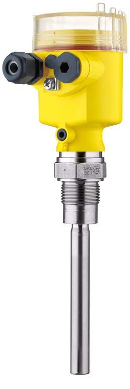
2.1 Aufbau.............................................................3
2.2 Arbeitsweise....................................................4
2.3 Lagerung und Transport..................................4
3 Montieren............................................................. 4
3.1 Allgemeine Hinweise.......................................4
3.2 Montagehinweise............................................4
4 An die Spannungsversorgung anschließen........
5
4.1 Anschluss vorbereiten.....................................5
4.2 Anschlussschritte............................................5
4.3 Anschlussplan.................................................6
5 In Betrieb nehmen............................................... 6
5.1 Allgemein........................................................6
5.2 Bedienelemente..............................................6
5.3 Funktionstabelle..............................................7
6 Instandhalten....................................................... 7
6.1 Instandhalten...................................................7
6.2 24 Stunden Service-Hotline.............................7
6.3 Vorgehen im Reparaturfall...............................7
7 Ausbauen............................................................. 7
7.1 Ausbauschritte................................................7
7.2 Entsorgen........................................................8
8 Anhang................................................................. 9
8.1 Technische Daten............................................9
8.2 Maße.............................................................11
8.3 Gewerbliche Schutzrechte............................13
32796-01-200130
Redaktionsstand: 2020-01-24
2 VEGAVIB S 61 •2 Produktbeschreibung
1 Zu Ihrer Sicherheit weise in dieser Betriebsanleitung, die lan-
desspezifischen Installationsstandards sowie
die geltenden Sicherheitsbestimmungen und
1.1 Autorisiertes Personal Unfallverhütungsvorschriften zu beachten.
Sämtliche in dieser Dokumentation beschriebe-
Eingriffe über die in der Betriebsanleitung
nen Handhabungen dürfen nur durch ausgebil-
beschriebenen Handhabungen hinaus dürfen
detes und vom Anlagenbetreiber autorisiertes
aus Sicherheits- und Gewährleistungsgründen
Fachpersonal durchgeführt werden.
nur durch vom Hersteller autorisiertes Personal
Bei Arbeiten am und mit dem Gerät ist immer vorgenommen werden. Eigenmächtige Um-
die erforderliche persönliche Schutzausrüstung bauten oder Veränderungen sind ausdrücklich
zu tragen. untersagt. Aus Sicherheitsgründen darf nur das
vom Hersteller benannte Zubehör verwendet
1.2 Bestimmungsgemäße werden.
Verwendung Um Gefährdungen zu vermeiden, sind die
Der VEGAVIB S 61 ist ein Sensor zur Grenz- auf dem Gerät angebrachten Sicherheits-
standerfassung. kennzeichen und -hinweise zu beachten und
deren Bedeutung in dieser Betriebsanleitung
Detaillierte Angaben zum Anwendungsbereich nachzulesen.
finden Sie in Kapitel "Produktbeschreibung".
1.5 EU-Konformität
1.3 Warnung vor Fehlgebrauch
Das Gerät erfüllt die gesetzlichen Anforderun-
Bei nicht sachgerechter oder nicht bestim- gen der zutreffenden EU-Richtlinien. Mit der
mungsgemäßer Verwendung können von die- CE-Kennzeichnung bestätigen wir die Konformi-
sem Produkt anwendungsspezifische Gefahren tät des Gerätes mit diesen Richtlinien.
ausgehen, so z. B. ein Überlauf des Behälters
durch falsche Montage oder Einstellung. Dies Die EU-Konformitätserklärung finden Sie auf
kann Sach-, Personen- oder Umweltschäden unserer Homepage.
zur Folge haben. Weiterhin können dadurch die
Schutzeigenschaften des Gerätes beeinträch- 1.6 Sicherheitshinweise für
tigt werden. Ex-Bereiche
Bei Ex-Anwendungen dürfen nur Geräte mit
1.4 Allgemeine entsprechender Ex-Zulassung eingesetzt wer-
Sicherheitshinweise den. Beachten Sie dabei die Ex-spezifischen
Das Gerät entspricht dem Stand der Technik Sicherheitshinweise. Diese sind Bestandteil der
unter Beachtung der üblichen Vorschriften und Betriebsanleitung und liegen jedem Gerät mit
Richtlinien. Es darf nur in technisch einwand- Ex-Zulassung bei.
freiem und betriebssicherem Zustand betrieben
werden. Der Betreiber ist für den störungsfreien 2 Produktbeschreibung
Betrieb des Gerätes verantwortlich. Beim Ein-
satz in aggressiven oder korrosiven Medien, bei 2.1 Aufbau
denen eine Fehlfunktion des Gerätes zu einer
Gefährdung führen kann, hat sich der Betreiber Lieferumfang
durch geeignete Maßnahmen von der korrekten Der Lieferumfang besteht aus:
Funktion des Gerätes zu überzeugen.
• Grenzstandsensor VEGAVIB S 61
Der Betreiber ist ferner verpflichtet, während der • Dokumentation
gesamten Einsatzdauer die Übereinstimmung –– Dieser Betriebsanleitung
32796-01-200130
der erforderlichen Arbeitssicherheitsmaß- –– Ex-spezifischen "Sicherheitshinweisen"
nahmen mit dem aktuellen Stand der jeweils (bei Ex-Ausführungen)
geltenden Regelwerke festzustellen und neue
Vorschriften zu beachten.
Durch den Anwender sind die Sicherheitshin-
VEGAVIB S 61 • 33 Montieren
2.2 Arbeitsweise 3 Montieren
Anwendungsbereich
Der VEGAVIB S 61 ist ein Grenzstandsensor mit 3.1 Allgemeine Hinweise
Schwingstab zur Grenzstanderfassung. Schaltpunkt
Er ist konzipiert für industrielle Einsätze in allen Grundsätzlich kann der VEGAVIB S 61 in jeder
Bereichen der Verfahrenstechnik und wird in beliebigen Lage eingebaut werden. Das Gerät
Schüttgütern eingesetzt. muss lediglich so montiert werden, dass sich
Typische Anwendungen sind Überlauf- und das Schwingelement auf Höhe des gewünsch-
Trockenlaufschutz. Durch sein einfaches und ten Schaltpunktes befindet.
robustes Messsystem lässt sich der VEGAVIB
Feuchtigkeit
S 61 nahezu unabhängig von den chemischen
und physikalischen Eigenschaften des Schütt-
gutes einsetzen.
Er arbeitet auch unter starken Fremdvibrationen
oder bei wechselndem Medium.
Funktionsüberwachung
Der Elektronikeinsatz des VEGAVIB S 61 über-
wacht kontinuierlich folgende Kriterien: Abb. 1: Maßnahmen gegen das Eindringen von
• Korrekte Schwingfrequenz Feuchtigkeit
• Leitungsbruch zum Piezoantrieb
Wird eine der genannten Funktionsstörungen Transport
erkannt oder fällt die Spannungsversorgung Halten Sie den VEGAVIB S 61 nicht am
aus, so nimmt die Elektronik einen definierten Schwingelement. Insbesondere bei Flansch-
Schaltzustand an, d. h. das Relais wird stromlos oder Rohrversionen kann der Sensor durch das
(sicherer Zustand). Gerätegewicht beschädigt werden.
Funktionsprinzip Entfernen Sie die Schutzkappe erst unmittelbar
Der Schwingstab wird piezoelektrisch ange- vor der Montage.
trieben und schwingt auf seiner mechanischen Handhabung
Resonanzfrequenz von ca. 360 Hz. Wird der Der Vibrationsgrenzschalter ist ein Messgerät
Schwingstab mit Medium bedeckt, ändert sich und muss entsprechend behandelt werden.
die Schwingamplitude. Diese Änderung wird Ein Verbiegen des Schwingelements führt zur
vom eingebauten Elektronikeinsatz erfasst und Zerstörung des Gerätes.
in einen Schaltbefehl umgewandelt.
Warnung:
Das Gehäuse darf nicht zum Einschrau-
2.3 Lagerung und Transport ben verwendet werden! Das Festziehen
Verpackung kann Schäden an der Drehmechanik
Ihr Gerät wurde auf dem Weg zum Einsatz- des Gehäuses verursachen.
ort durch eine Verpackung geschützt. Dabei Verwenden Sie zum Einschrauben den
sind die üblichen Transportbeanspruchungen Sechskant oberhalb des Gewindes.
durch eine Prüfung in Anlehnung an ISO 4180
abgesichert.
Die Verpackung besteht aus Karton, ist umwelt-
3.2 Montagehinweise
verträglich und wieder verwertbar. Entsorgen Stutzen
32796-01-200130
Sie das anfallende Verpackungsmaterial über Das Schwingelement sollte möglichst frei in den
spezialisierte Recyclingbetriebe. Behälter ragen, um Ablagerungen zu verhin-
dern.
4 VEGAVIB S 61 •4 An die Spannungsversorgung anschließen
Befüllöffnung oder Querschnitt einsetzen, wechseln Sie die
Bauen Sie das Gerät so ein, dass der Schwing- Dichtung oder verwenden Sie eine geeignete
stab nicht direkt in den Befüllstrom ragt. Kabelverschraubung.
Waagerechte Montage
4.2 Anschlussschritte
Gehen Sie wie folgt vor:
1. Gehäusedeckel abschrauben
2. Überwurfmutter der Kabelverschraubung lö-
20° sen und Verschlussstopfen herausnehmen
3. Anschlusskabel ca. 10 cm (4 in) abmanteln,
Aderenden ca. 1 cm (0.4 in) abisolieren
4. Kabel durch die Kabelverschraubung in den
Sensor schieben
5. Öffnungshebel der Klemmen mit einem
Abb. 2: Waagerechte Montage Schraubendreher anheben (siehe nachfol-
gende Abbildung)
6. Aderenden nach Anschlussplan in die
4 An die Spannungsversor-
offenen Klemmen stecken
gung anschließen 7. Öffnungshebel der Klemmen nach unten
drücken, die Klemmenfeder schließt hörbar
4.1 Anschluss vorbereiten 8. Korrekten Sitz der Leitungen in den Klem-
Sicherheitshinweise beachten men durch leichtes Ziehen prüfen
Beachten Sie grundsätzlich folgende Sicher- 9. Überwurfmutter der Kabelverschraubung
heitshinweise: fest anziehen. Der Dichtring muss das
• Nur in spannungslosem Zustand anschlie- Kabel komplett umschließen
ßen 10. Eventuell neuen Abgleich durchführen
• Sicherheitshinweise für Ex-Anwendungen 11. Gehäusedeckel verschrauben
beachten
Schließen Sie die Spannungsversorgung ge- Der elektrische Anschluss ist somit fertig
mäß den nachfolgenden Anschlussbildern an. gestellt.
Der Elektronikeinsatz mit Relaisausgang ist in
Schutzklasse I ausgeführt. Zur Einhaltung die-
ser Schutzklasse ist es zwingend erforderlich,
dass der Schutzleiter an der inneren Schutzlei-
teranschlussklemme angeschlossen wird.
Die Daten für die Spannungsversorgung finden
Sie in Kapitel "Technische Daten".
Anschlusskabel
Der VEGAVIB S 61 wird mit handelsüblichem
Kabel mit rundem Querschnitt angeschlossen.
Ein Kabelaußendurchmesser von 5 … 9 mm
(0.2 … 0.35 in) stellt die Dichtwirkung der Ka- Abb. 3: Anschlussschritte 5 und 6
belverschraubung sicher.
32796-01-200130
Stellen Sie sicher, dass das verwendete Kabel
die für die maximal auftretende Umgebungs-
temperatur erforderliche Temperaturbeständig-
keit und Brandsicherheit aufweist.
Wenn Sie Kabel mit anderem Durchmesser
VEGAVIB S 61 • 55 In Betrieb nehmen
4.3 Anschlussplan + - + -
5
4 345678
L N min max
6
+ - + -
1 2 3 4 5 6 7 8 1 2
Abb. 6: Belegung: NPN und PNP
1 2 3
1 NPN-Verhalten
Abb. 4: Ausführung: Elektronik „R“ - Doppelrelais 2 PNP-Verhalten
(DPDT)
1 Spannungsversorgung
2 Relais 1 5 In Betrieb nehmen
3 Relais 2
4 Kontrollleuchte
5 Dichteanpassung (DIL-Schalter)
5.1 Allgemein
6 Betriebsartenumschaltung min/max (DIL-Schalter)
Funktion/Aufbau
Auf dem Elektronikeinsatz finden Sie folgende
Anschluss an eine SPS Anzeige- und Bedienelemente:
Wenn induktive Lasten oder höhere Ströme
geschaltet werden, wird die Goldplattierung auf • DIL-Schalter zur Einstellung des Dichtebe-
reiches
der Relaiskontaktfläche dauerhaft beschädigt.
Der Kontakt ist danach nicht mehr zum Schalten • DIL-Schalter zur Betriebsartenumschaltung
- min./max.
von Kleinspannungsstromkreisen geeignet.
Induktive Lasten ergeben sich auch durch den
• Kontrollleuchte (LED)
Anschluss an einen SPS-Ein- oder Ausgang 5.2 Bedienelemente
und/oder in Kombination mit langen Leitungen.
Sehen Sie hier zwingend Maßnahmen zur Einstellung des Dichtebereiches
Funkenlöschung zum Schutz des Relaiskon- Mit diesem DIL-Schalter können Sie den Schalt-
taktes vor (z. B. Z-Diode) oder nutzen Sie eine punkt auf Schüttgüter einstellen, die eine Dichte
Elektronikausführung mit Transistor-Ausgang. zwischen 0,1 und 0,3 g/cm³ haben.
Wir empfehlen den VEGAVIB S 61 so anzu- Der Schalter des VEGAVIB S 61 steht werksei-
schließen, dass der Schaltstromkreis bei Grenz- tig auf dem großen Gewichtssymbol (> 0,3 g/
standmeldung, Leitungsbruch oder Störung cm³). Bei besonders leichten Schüttgütern
geöffnet ist (sicherer Zustand). stellen Sie den DIL-Schalter auf das kleine Ge-
Die Relais sind immer im Ruhezustand darge- wichtssymbol (0,1 … 0,3 g/cm³). Damit wird der
stellt. VEGAVIB S 61 empfindlicher und kann leichte
Schüttgüter sicher detektieren.
3
2 1 2 3 4
Betriebsartenumschaltung
Mit der Betriebsartenumschaltung (min./max.)
min max
4 können Sie den Schaltzustand des Relais
ändern. Sie können damit die gewünschte
1 2 3 4 Betriebsart gemäß "Funktionstabelle" einstellen
(max. - Maximalstanderfassung bzw. Über-
1 laufschutz, min. - Minimalstanderfassung bzw.
Trockenlaufschutz).
Abb. 5: Ausführung: Elektronik „T“ - Transistor (NPN/
32796-01-200130
PNP) Wir empfehlen, den Anschluss im Ruhestrom-
1 Spannungsversorgung prinzip (Relaiskontakt bei Erreichen des Schalt-
2 Kontrollleuchte punktes stromlos), da das Relais bei erkannter
3 Dichteanpassung (DIL-Schalter) Störung den gleichen (sicheren) Zustand
4 Betriebsartenumschaltung min/max (DIL-Schalter) annimmt.
6 VEGAVIB S 61 •6 Instandhalten
Kontrollleuchte Reinigung
Kontrollleuchte (LED) zur Anzeige des Schalt- Die Reinigung trägt dazu bei, dass Typschild
zustandes und Markierungen auf dem Gerät sichtbar sind.
• Grün = Relais stromführend Beachten Sie hierzu folgendes:
• Rot = Relais stromlos
• Nur Reinigungsmittel verwenden, die
• Rot (blinkt) = Störung Gehäuse, Typschild und Dichtungen nicht
angreifen
5.3 Funktionstabelle • Nur Reinigungsmethoden einsetzen, die der
Die folgende Tabelle gibt eine Übersicht über Geräteschutzart entsprechen
die Schaltzustände in Abhängigkeit von der
eingestellten Betriebsart und dem Füllstand. 6.2 24 Stunden Service-Hotline
Füllstand Schaltzu- Kontroll-
Sollten diese Maßnahmen dennoch zu keinem
stand leuchte Ergebnis führen, rufen Sie in dringenden
Fällen die VEGA Service-Hotline an unter Tel.
Betriebsart geschlos-
+49 1805 858550.
max. sen
Überlauf- Die Hotline steht Ihnen auch außerhalb der
schutz üblichen Geschäftszeiten an 7 Tagen in der
Grün Woche rund um die Uhr zur Verfügung. Da
Betriebsart offen wir diesen Service weltweit anbieten, erfolgt
max. die Unterstützung in englischer Sprache. Der
Überlauf- Service ist kostenfrei, es fallen lediglich die
schutz üblichen Telefongebühren an.
Rot
Betriebsart
min.
geschlos-
sen
6.3 Vorgehen im Reparaturfall
Trockenlauf-
Ein Geräterücksendeblatt sowie detallierte
schutz Informationen zur Vorgehensweise finden Sie im
Grün Downloadbereich auf www.vega.com.
Betriebsart offen Sie helfen uns damit, die Reparatur schnell und
min. ohne Rückfragen durchzuführen.
Trockenlauf-
Sollte eine Reparatur erforderlich sein, gehen
schutz
Rot Sie folgendermaßen vor:
Ausfall der beliebig offen • Für jedes Gerät ein Formular ausdrucken
Spannungs- und ausfüllen
versorgung
• Das Gerät reinigen und bruchsicher verpa-
(Betriebsart cken
min./max.) • Das ausgefüllte Formular und eventuell ein
Störung beliebig offen Sicherheitsdatenblatt außen auf der Verpa-
ckung anbringen
• Bitte erfragen Sie die Adresse für die
Rücksendung bei der für Sie zuständigen
blinkt rot Vertretung. Sie finden diese auf unserer
Homepage www.vega.com.
6 Instandhalten
7 Ausbauen
6.1 Instandhalten
32796-01-200130
7.1 Ausbauschritte
Wartung Warnung:
Bei bestimmungsgemäßer Verwendung ist Achten Sie vor dem Ausbauen auf ge-
im Normalbetrieb keine besondere Wartung fährliche Prozessbedingungen wie z. B.
erforderlich.
VEGAVIB S 61 • 77 Ausbauen
Druck im Behälter, hohe Temperaturen,
aggressive oder toxische Medien etc.
Beachten Sie die Kapitel "Montieren" und "An
die Spannungsversorgung anschließen" und
führen Sie die dort angegebenen Schritte sinn-
gemäß umgekehrt durch.
7.2 Entsorgen
Das Gerät besteht aus Werkstoffen, die von dar-
auf spezialisierten Recyclingbetrieben wieder
verwertet werden können. Wir haben hierzu die
Elektronik leicht trennbar gestaltet und verwen-
den recyclebare Werkstoffe.
WEEE-Richtlinie
Das Gerät fällt nicht in den Geltungsbereich
der EU-WEEE-Richtlinie. Nach Artikel 2 dieser
Richtlinie sind Elektro- und Elektronikgeräte da-
von ausgenommen, wenn sie Teil eines anderen
Gerätes sind, das nicht in den Geltungsbereich
der Richtlinie fällt. Dies sind u. a. ortsfeste
Industrieanlagen.
Führen Sie das Gerät direkt einem spezialisier-
ten Recyclingbetrieb zu und nutzen Sie dafür
nicht die kommunalen Sammelstellen.
Sollten Sie keine Möglichkeit haben, das Altge-
rät fachgerecht zu entsorgen, so sprechen Sie
mit uns über Rücknahme und Entsorgung.
32796-01-200130
8 VEGAVIB S 61 •8 Anhang
8 Anhang
8.1 Technische Daten
Allgemeine Daten
Werkstoff 316L entspricht 1.4404 oder 1.4435
Werkstoffe, medienberührt
ƲƲ Prozessanschluss 316L
ƲƲ Schwingstab 316L, 318 S13 (1.4462)
ƲƲ Verlängerungsrohr 316L
ƲƲ Prozessdichtung Klingersil C-4400
Werkstoffe, nicht medienberührt
ƲƲ Gehäuse Kunststoff PBT (Polyester)
ƲƲ Gehäusedeckel Kunststoff PA 12 (Polyamid, klar)
ƲƲ Dichtung zwischen Gehäuse und Silikon
Gehäusedeckel
ƲƲ Erdungsklemme 316L
ƲƲ Kabelverschraubung PA, Edelstahl, Messing
ƲƲ Dichtung Kabelverschraubung NBR
ƲƲ Verschlussstopfen Kabelverschrau- PA
bung
Prozessanschlüsse
ƲƲ Rohrgewinde, zylindrisch (DIN 3852- G1, G1½
A)
ƲƲ Rohrgewinde, konisch 1 NPT, 1¼ NPT, 1½ NPT
(ASME B1.20.1) 1 NPT: Kerndurchmesser des Innengewindes > 29,2 mm
(1.15 in)
ƲƲ Rohrgewinde, zylindrisch (EN 10226) R1, R1½
Sensorlänge (L) (A) 148, (C) 500, (D) 1000, (E) 1500 mm (5.827, 19.69,
39.37, 59.06 in)
Sensorlängen-Genauigkeit ± 2 mm (± 0.079 in)
Gewicht ca. 1150 g
Max. seitliche Belastung 400 N
Anzugsmoment für NPT-Kabelverschraubungen und Conduit-Rohre
ƲƲ Kunststoffgehäuse max. 10 Nm (7.376 lbf ft)
ƲƲ Aluminium-/Edelstahlgehäuse max. 50 Nm (36.88 lbf ft)
Ausgangsgröße
Relaisausgang 2 potenzialfreie Umschaltkontakte (DPDT)
ƲƲ Schaltspannung max. 253 V AC/DC
32796-01-200130
Bei Stromkreisen > 150 V AC/DC müssen sich die Re-
laiskontakte im selben Stromkreis befinden.
ƲƲ Schaltstrom max. 3 A AC (cos phi > 0,9), 1 A DC
VEGAVIB S 61 • 98 Anhang
ƲƲ Schaltleistung 750 VA AC, 40 W DC (bei U < 40 V DC)
Wenn induktive Lasten oder höhere Ströme geschaltet
werden, wird die Goldplattierung auf der Relaiskontakt-
fläche dauerhaft beschädigt. Der Kontakt ist danach
nicht mehr zum Schalten von Kleinsignalstromkreisen
geeignet.
ƲƲ Kontaktwerkstoff AgNi oder AgSnO2 mit je 3 µm Goldplattierung
ƲƲ Hinweis
Transistorausgang Potenzialfreier Transistorausgang
ƲƲ Schaltspannung max. 55 V DC
ƲƲ Schaltstrom max. 400 mA
ƲƲ Sperrstrom < 100 µA
Betriebsarten (umschaltbar) min./max.
Schaltverzögerung ein: ca. 0,5 s
aus: ca. 1 s
Umgebungsbedingungen
Umgebungstemperatur -40 … +80 °C
Lager- und Transporttemperatur -40 … +80 °C
Prozessbedingungen
Prozessdruck -1 … 16 bar/-100 … 1600 kPa
Prozesstemperatur -50 … +150 °C
Dichte > 0,1 g/cm³
Elektromechanische Daten
Optionen der Kabeleinführung
ƲƲ Kabeleinführung M20 x 1,5
ƲƲ Kabelverschraubung M20 x 1,5
ƲƲ Blindstopfen M20 x 1,5
Federkraftklemmen für Aderquerschnitt bis 1,5 mm² (AWG 16)
Bedienelemente
Betriebsartenschalter
ƲƲ Min. Minimalstanderfassung bzw. Trockenlaufschutz
ƲƲ Max. Maximalstanderfassung bzw. Überlaufschutz
Spannungsversorgung
Relaisausgang
ƲƲ Betriebsspannung 20 … 253 V AC, 50/60 Hz, 20 … 72 V DC (bei
32796-01-200130
U > 60 V DC darf die Umgebungstemperatur max.
50 °C/122 °F betragen)
ƲƲ Leistungsaufnahme 1 … 8 VA (AC), ca. 1,3 W (DC)
10 VEGAVIB S 61 •8 Anhang
Transistorausgang
ƲƲ Betriebsspannung 10 … 55 V DC
ƲƲ Leistungsaufnahme max. 0,5 W
Elektrische Schutzmaßnahmen
Schutzart IP66/IP67 nach IEC 60529, Type 4X nach NEMA
Einsatzhöhe über Meeresspiegel bis 5000 m (16404 ft)
Überspannungskategorie
ƲƲ bis 2000 m (6562 ft) III
ƲƲ bis 5000 m (16404 ft) II
Schutzklasse - Transistorausgang II
Schutzklasse - Relaisausgang I
Zulassungen
ATEX II 1/3 D IP66 T (optional)
8.2 Maße
~ 69 mm
ø 81 mm
145 mm
M20 x 1,5
20 mm
SW 41
G1 A
148 mm
ø 29 mm
105 mm
ø16 mm
Abb. 7: Ausführung: Sensorlänge A
32796-01-200130
VEGAVIB S 61 • 118 Anhang
~ 69 mm
(2.72")
ø 81 mm
(3.19")
153 mm
(6.02")
M20 x 1,5
22 mm
(0.87")
SW 46
G1½ A
ø 29 mm
(1.14")
L
105 mm
(4.13")
ø16 mm
(0.63")
Abb. 8: Ausführung: Sensorlänge C, D, E
L Sensorlänge, siehe Kapitel "Technische Daten"
32796-01-200130
12 VEGAVIB S 61 •8 Anhang
8.3 Gewerbliche Schutzrechte
VEGA product lines are global protected by industrial property rights. Further information see
www.vega.com.
Only in U.S.A.: Further information see patent label at the sensor housing.
VEGA Produktfamilien sind weltweit geschützt durch gewerbliche Schutzrechte.
Nähere Informationen unter www.vega.com.
Les lignes de produits VEGA sont globalement protégées par des droits de propriété intellectuel-
le. Pour plus d'informations, on pourra se référer au site www.vega.com.
VEGA lineas de productos están protegidas por los derechos en el campo de la propiedad indus-
trial. Para mayor información revise la pagina web www.vega.com.
Линии продукции фирмы ВЕГА защищаются по всему миру правами на интеллектуальную
собственность. Дальнейшую информацию смотрите на сайте www.vega.com.
VEGA系列产品在全球享有知识产权保护。
进一步信息请参见网站Contents
Operating instructions
DE Betriebsanleitung 2 FR Mise en service 26
EN Operating instructions 14 ES Manual de instrucciones 38
Contents
1 For your safety................................................... 15
1.1 Authorised personnel....................................15
1.2 Appropriate use.............................................15
1.3 Warning about incorrect use..........................15
1.4 General safety instructions............................15
1.5 EU conformity................................................15
1.6 Safety instructions for Ex areas.....................15
2 Product description.......................................... 15
2.1 Configuration.................................................15
2.2 Principle of operation.....................................15
2.3 Storage and transport....................................16
3 Mounting............................................................ 16
3.1 General instructions......................................16
3.2 Mounting instructions....................................16
4 Connecting to power supply............................ 17
4.1 Preparing the connection..............................17
4.2 Connection procedure...................................17
4.3 Wiring plan....................................................18
5 Setup.................................................................. 18
5.1 General information.......................................18
5.2 Adjustment elements.....................................18
5.3 Function table................................................19
6 Maintenance...................................................... 19
6.1 Maintenance..................................................19
6.2 24 hour service hotline..................................19
6.3 How to proceed if a repair is necessary.........19
7 Dismount............................................................ 19
7.1 Dismounting steps.........................................19
7.2 Disposal........................................................20
8 Supplement........................................................ 21
8.1 Technical data...............................................21
8.2 Dimensions...................................................23
8.3 Industrial property rights................................25
32796-01-200130
Editing status: 2020-01-24
14 VEGAVIB S 61 •2 Product description
1 For your safety out only by personnel authorised by the manu-
facturer. Arbitrary conversions or modifications
are explicitly forbidden. For safety reasons, only
1.1 Authorised personnel the accessory specified by the manufacturer
All operations described in this documentation must be used.
must be carried out only by trained, qualified
To avoid any danger, the safety approval
personnel authorised by the plant operator.
markings and safety tips on the device must
During work on and with the device, the requi- also be observed and their meaning read in this
red personal protective equipment must always operating instructions manual.
be worn.
1.5 EU conformity
1.2 Appropriate use The device fulfils the legal requirements of the
The VEGAVIB S 61 is a sensor for point level applicable EU directives. By affixing the CE
detection. marking, we confirm the conformity of the instru-
You can find detailed information about the area ment with these directives.
of application in chapter "Product description". The EU conformity declaration can be found on
our homepage.
1.3 Warning about incorrect use
Inappropriate or incorrect use of this product 1.6 Safety instructions for Ex
can give rise to application-specific hazards, areas
e.g. vessel overfill through incorrect mounting or
For Ex applications, only devices with corres-
adjustment. Damage to property and persons or
ponding Ex approval may be used. Observe the
environmental contamination can result. Also,
Ex-specific safety instructions. These are an in-
the protective characteristics of the instrument
tegral part of the operating instructions and are
can be impaired.
enclosed with every device with Ex approval.
1.4 General safety instructions
2 Product description
This is a state-of-the-art instrument complying
with all prevailing regulations and directives. The
instrument must only be operated in a techni-
2.1 Configuration
cally flawless and reliable condition. The opera- Scope of delivery
tor is responsible for the trouble-free operation The scope of delivery encompasses:
of the instrument. When measuring aggressive
or corrosive media that can cause a dangerous • VEGAVIB S 61 point level switch
situation if the instrument malfunctions, the • Documentation
operator has to implement suitable measures to –– This operating instructions manual
make sure the instrument is functioning properly. –– Ex-specific "Safety instructions" (with Ex
versions)
During the entire duration of use, the user is
obliged to determine the compliance of the
necessary occupational safety measures with 2.2 Principle of operation
the current valid rules and regulations and also
take note of new regulations. Application area
VEGAVIB S 61 is a point level sensor with vibra-
The safety instructions in this operating ting rod for point level detection.
instructions manual, the national installation
standards as well as the valid safety regulations It is designed for industrial use in all areas of
process technology and is used in bulk solids.
32796-01-200130
and accident prevention rules must be observed
by the user. Typical applications are overfill and dry run
For safety and warranty reasons, any invasive protection. Thanks to its simple and robust
work on the device beyond that described in the measuring system, VEGAVIB S 61 is virtually
operating instructions manual may be carried unaffected by the chemical and physical proper-
VEGAVIB S 61 • 153 Mounting
ties of the bulk solid. Moisture
It also works when subjected to strong external
vibrations or changing products.
Function monitoring
The electronics module of VEGAVIB S 61 conti-
nuously monitors the following criteria:
• Correct vibrating frequency
• Line break to the piezo drive
Abb. 9: Measures against moisture ingress
If one of the stated malfunctions is detected or
in case of voltage supply, the electronics takes
on a defined switching status, i.e. the relay Transport
deenergises (safe state). Do not hold VEGAVIB S 61 on the vibrating ele-
ment. Especially with flange and tube versions,
Functional principle the sensor can be damaged by the weight of the
The vibrating rod is piezoelectrically energi- instrument.
sed and vibrates at its mechanical resonance Remove the protective cover just before moun-
frequency of approx. 360 Hz. When the vibrating ting.
rod is submerged in the product, the vibration
amplitude changes. This change is detected by Handling
the integrated electronics module and conver- The vibrating level switch is a measuring instru-
ted into a switching command. ment and must be treated accordingly. Bending
the vibrating element will destroy the instrument.
2.3 Storage and transport Warning:
The housing must not be used to screw
Packaging the instrument in! Applying tightening
Your instrument was protected by packaging force can damage internal parts of the
during transport. Its capacity to handle normal housing.
loads during transport is assured by a test
Use the hexagon above the thread for
based on ISO 4180.
screwing in.
The packaging consists of cardboard. This
material is environment-friendly and recyclable.
Dispose of the packaging material via specia- 3.2 Mounting instructions
lised recycling companies.
Mounting socket
The vibrating element should protrude into the
3 Mounting vessel to avoid buildup.
3.1 General instructions Filling opening
Mount the instrument in such a way that the
Switching point vibrating rod does not protrude directly into the
In general, VEGAVIB S 61 can be installed filling stream.
in any position. The instrument only has to
be mounted in such a way that the vibrating
element is at the height of the desired switching
point.
32796-01-200130
16 VEGAVIB S 61 •4 Connecting to power supply
Horizontal mounting 1. Unscrew the housing lid
2. Loosen compression nut of the cable gland
and remove blind plug
3. Remove approx. 10 cm (4 in) of the cable
mantle, strip approx. 1 cm (0.4 in) of insula-
20°
tion from the ends of the individual wires
4. Insert the cable into the sensor through the
cable entry
5. Lift the opening levers of the terminals with
a screwdriver (see following illustration)
6. Insert the wire ends into the open terminals
Abb. 10: Horizontal mounting according to the wiring plan
7. Press down the opening levers of the
4 Connecting to power terminals, you will hear the terminal spring
closing
supply
8. Check the hold of the wires in the terminals
by lightly pulling on them
4.1 Preparing the connection
9. Tighten the compression nut of the cable
Note safety instructions entry gland. The seal ring must completely
Always keep in mind the following safety encircle the cable
instructions: 10. If necessary, carry out a fresh adjustment
• Connect only in the complete absence of 11. Screw the housing lid back on
line voltage
The electrical connection is finished.
• Take note of safety instructions for Ex
applications
Connect the voltage supply according to the
following connection diagrams. The electronics
module with relay output is designed in protec-
tion class I. To maintain this protection class, it is
absolutely necessary that the ground conductor
be connected to the internal ground terminal.
The data for power supply are specified in chap-
ter "Technical data".
Connection cable
VEGAVIB S 61 is connected with standard
cable with round cross section. An outer cable Abb. 11: Connection steps 5 and 6
diameter of 5 … 9 mm (0.2 … 0.35 in) ensures
the seal effect of the cable gland.
Make sure that the cable used has the required
temperature resistance and fire safety for max.
occurring ambient temperature
If cable with a different diameter or wire cross
section is used, exchange the seal or use an
appropriate cable connection.
32796-01-200130
4.2 Connection procedure
Proceed as follows:
VEGAVIB S 61 • 175 Setup
4.3 Wiring plan + - + -
5
4 345678
L N min max
6
+ - + -
1 2 3 4 5 6 7 8 1 2
Abb. 14: Assignment: NPN and PNP
1 2 3
1 NPN action
Abb. 12: Version: Electronics „R“ - double relay (DPDT) 2 PNP action
1 Voltage supply
2 Relay 1
3 Relay 2 5 Setup
4 Control lamp
5 Density adaptation (DIL switch)
6 Mode adjustment min./max. (DIL switch)
5.1 General information
Function/Configuration
Connection to a PLC On the electronics module you will find the
If inductive loads or stronger currents are swit- following display and adjustment elements:
ched through, the gold plating on the relay con-
tact surface will be permanently damaged. The • DIL switch for adjustment of the density
range
contact is then no longer suitable for switching
low-voltage circuits. • DIL switch for mode adjustment - min./max.
• Control lamp (LED)
Inductive loads also result from the connection
to a PLC input or output and/or in combination 5.2 Adjustment elements
with long cables. It is imperative that you take
measures to extinguish sparks to protect the Adjustment of the density range
relay contact (e.g. Z diode) or use an electronic With this DIL switch, the switching point can be
version with transistor output. set to bulk solids having a density between 0.1
and 0.3 g/cm³.
We recommend connecting VEGAVIB S 61 in
such a way that the switching circuit is open As default setting, the switch of VEGAVIB S
when there is a level signal, line break or failure 61 is set to the large weight symbol (> 0.03 g/
(safe state). cm³). In very light solids you should turn the DIL
switch to the small weight symbol (0.1 … 0.3 g/
The relays are always shown in non-operative
cm³). By doing this, VEGAVIB S 61 is more sen-
condition.
sitive and can detect light solids reliably.
3
2 1 2 3 4 Mode adjustment
min max
With the mode setting (min./max.) you can
4 change the switching condition of the relay.
You can set the required mode according to
1 2 3 4 the "Function table" (max. - max. detection or
overflow protection, min. - min. detection or dry
1 run protection).
Abb. 13: Version: Electronics „T“ - transistor (NPN/ We recommend connecting according to the
PNP) idle current principle (relay contact deenergizes
when the switching point is reached), because
32796-01-200130
1 Voltage supply
2 Control lamp the relay always takes on the same (safe) state
3 Density adaptation (DIL switch) if a failure is detected.
4 Mode adjustment min./max. (DIL switch)
Control lamp
Control lamp (LED) for indication of the swit-
18 VEGAVIB S 61 •6 Maintenance
ching condition kings on the instrument are visible.
• green = relay energized Take note of the following:
• red = relay deenergized
• Use only cleaning agents which do not cor-
• red (flashing) = failure rode the housings, type label and seals
5.3 Function table • Use only cleaning methods corresponding
to the housing protection rating
The following table provides an overview of
the switching conditions depending on the set 6.2 24 hour service hotline
mode and the level. Should these measures not be successful,
Level Switching Control
please call in urgent cases the VEGA service
status lamp hotline under the phone no. +49 1805 858550.
Mode max. closed The hotline is manned 7 days a week round-
the-clock. Since we offer this service worldwide,
Overflow
protection the support is only available in the English
language. The service is free, only standard call
Green charges are incurred.
Mode max. open
Overflow 6.3 How to proceed if a repair is
protection
necessary
Red You can find an instrument return form as
Mode min. closed well as detailed information about the proce-
Dry run pro- dure in the download area of our homepage:
tection www.vega.com.
Green By doing this you help us carry out the repair
quickly and without having to call back for nee-
Mode min. open
ded information.
Dry run pro-
tection If a repair is necessary, please proceed as
follows:
Red
• Print and fill out one form per instrument
Failure of
the supply
any open
• Clean the instrument and pack it damage-
proof
voltage
(min./max.
• Attach the completed form and, if need
be, also a safety data sheet outside on the
mode)
packaging
Fault any open • Please contact the agency serving you to
get the address for the return shipment.
You can find the agency on our home page
www.vega.com.
flashes red
7 Dismount
6 Maintenance
7.1 Dismounting steps
6.1 Maintenance Warning:
Before dismounting, be aware of dan-
Maintenance
32796-01-200130
gerous process conditions such as e.g.
If the device is used properly, no special mainte- pressure in the vessel, high temperatu-
nance is required in normal operation. res, corrosive or toxic products etc.
Cleaning
Take note of chapters "Mounting" and "Connec-
The cleaning helps that the type label and mar-
VEGAVIB S 61 • 197 Dismount
ting to voltage supply" and carry out the listed
steps in reverse order.
7.2 Disposal
The instrument consists of materials which can
be recycled by specialised recycling companies.
We use recyclable materials and have designed
the electronics to be easily separable.
WEEE directive
The instrument does not fall in the scope of the
EU WEEE directive. Article 2 of this Directive ex-
empts electrical and electronic equipment from
this requirement if it is part of another instrument
that does not fall in the scope of the Directive.
These include stationary industrial plants.
Pass the instrument directly on to a specialised
recycling company and do not use the municipal
collecting points.
If you have no way to dispose of the old instru-
ment properly, please contact us concerning
return and disposal.
32796-01-200130
20 VEGAVIB S 61 •8 Supplement
8 Supplement
8.1 Technical data
General data
Material 316L corresponds to 1.4404 or 1.4435
Materials, wetted parts
ƲƲ Process fitting 316L
ƲƲ Vibrating rod 316L, 318 S13 (1.4462)
ƲƲ Extension tube 316L
ƲƲ Process seal Klingersil C-4400
Materials, non-wetted parts
ƲƲ Housing Plastic PBT (Polyester)
ƲƲ Housing lid Plastic PA 12 (polyamide, clear)
ƲƲ Seal between housing and housing lid Silicone
ƲƲ Ground terminal 316L
ƲƲ Cable gland PA, stainless steel, brass
ƲƲ Sealing, cable gland NBR
ƲƲ Blind plug, cable gland PA
Process fittings
ƲƲ Pipe thread, cylindrical (DIN 3852-A) G1, G1½
ƲƲ Pipe thread, conical (ASME B1.20.1) 1 NPT, 1¼ NPT, 1½ NPT
1 NPT: core diameter of the internal thread > 29.2 mm
(1.15 in)
ƲƲ Pipe thread, cylindrical (EN 10226) R1, R1½
Sensor length (L) (A) 148, (C) 500, (D) 1000, (E) 1500 mm (5.827, 19.69,
39.37, 59.06 in)
Sensor lengths - accuracy ± 2 mm (± 0.079 in)
Weight approx. 1150 g
Max. lateral load 400 N
Torque for NPT cable glands and Conduit tubes
ƲƲ Plastic housing max. 10 Nm (7.376 lbf ft)
ƲƲ Aluminium/Stainless steel housing max. 50 Nm (36.88 lbf ft)
Output variable
Relay output 2 floating spdts (DPDT)
ƲƲ Switching voltage max. 253 V AC/DC
With circuits > 150 V AC/DC, the relay contacts must be
in the same circuit.
32796-01-200130
ƲƲ Switching current max. 3 A AC (cos phi > 0.9), 1 A DC
VEGAVIB S 61 • 218 Supplement
ƲƲ Breaking capacity 750 VA AC, 40 W DC (at U < 40 V DC)
If inductive loads or stronger currents are switched
through, the gold plating on the relay contact surface will
be permanently damaged. The contact is then no longer
suitable for switching low-level signal circuits.
ƲƲ Contact material AgNi or AgSnO2 each with 3 µm gold plating
ƲƲ Note
Transistor output Floating transistor output
ƲƲ Switching voltage max. 55 V DC
ƲƲ Switching current max. 400 mA
ƲƲ Blocking current < 100 µA
Modes (switchable) min./max.
Switching delay on: approx. 0.5 s
off: approx. 1 s
Ambient conditions
Ambient temperature -40 … +80 °C
Storage and transport temperature -40 … +80 °C
Process conditions
Process pressure -1 … 16 bar/-100 … 1600 kPa
Process temperature -50 … +150 °C
Density > 0.1 g/cm³
Electromechanical data
Options of the cable entry
ƲƲ Cable entry M20 x 1.5
ƲƲ Cable gland M20 x 1.5
ƲƲ Blind plug M20 x 1.5
Spring-loaded terminals for wire cross-section up to 1.5 mm² (AWG 16)
Adjustment elements
Mode switch
ƲƲ Min. Min. detection or dry run protection
ƲƲ Max. Max. detection or overflow protection
Voltage supply
Relay output
ƲƲ Operating voltage 20 … 253 V AC, 50/60 Hz, 20 … 72 V DC (at
U >60 V DC, the ambient temperature can be max.
32796-01-200130
50 °C/122 °F)
ƲƲ Power consumption 1 … 8 VA (AC), approximately 1.3 W (DC)
Transistor output
ƲƲ Operating voltage 10 … 55 V DC
22 VEGAVIB S 61 •8 Supplement
ƲƲ Power consumption max. 0.5 W
Electrical protective measures
Protection rating IP66/IP67 acc. to IEC 60529, Type 4X acc. to NEMA
Altitude above sea level up to 5000 m (16404 ft)
Overvoltage category
ƲƲ up to 2000 m (6562 ft) III
ƲƲ up to 5000 m (16404 ft) II
Protection class - Transistor output II
Protection class - Relay output I
Approvals
ATEX II 1/3 D IP66 T (optional)
8.2 Dimensions
~ 69 mm
ø 81 mm
145 mm
M20 x 1,5
20 mm
SW 41
G1 A
148 mm
ø 29 mm
105 mm
ø16 mm
Abb. 15: Version: Sensor length A
32796-01-200130
VEGAVIB S 61 • 238 Supplement
~ 69 mm
(2.72")
ø 81 mm
(3.19")
153 mm
(6.02")
M20 x 1,5
22 mm
(0.87")
SW 46
G1½ A
ø 29 mm
(1.14")
L
105 mm
(4.13")
ø16 mm
(0.63")
Abb. 16: Version: Sensor length C, D, E
L Sensor length, see chapter "Technical data"
32796-01-200130
24 VEGAVIB S 61 •8 Supplement
8.3 Industrial property rights
VEGA product lines are global protected by industrial property rights. Further information see
www.vega.com.
Only in U.S.A.: Further information see patent label at the sensor housing.
VEGA Produktfamilien sind weltweit geschützt durch gewerbliche Schutzrechte.
Nähere Informationen unter www.vega.com.
Les lignes de produits VEGA sont globalement protégées par des droits de propriété intellectuel-
le. Pour plus d'informations, on pourra se référer au site www.vega.com.
VEGA lineas de productos están protegidas por los derechos en el campo de la propiedad indus-
trial. Para mayor información revise la pagina web www.vega.com.
Линии продукции фирмы ВЕГА защищаются по всему миру правами на интеллектуальную
собственность. Дальнейшую информацию смотрите на сайте www.vega.com.
VEGA系列产品在全球享有知识产权保护。
进一步信息请参见网站Table des matières
Mise en service
DE Betriebsanleitung 2 FR Mise en service 26
EN Operating instructions 14 ES Manual de instrucciones 38
Table des matières
1 Pour votre sécurité............................................ 27
1.1 Personnel autorisé.........................................27
1.2 Utilisation appropriée.....................................27
1.3 Avertissement contre les utilisations incorrec-
tes27
1.4 Consignes de sécurité générales..................27
1.5 Conformité UE...............................................27
1.6 Consignes de sécurité pour atmosphères Ex....
27
2 Description du produit...................................... 27
2.1 Structure........................................................27
2.2 Fonctionnement............................................28
2.3 Stockage et transport....................................28
3 Montage............................................................. 28
3.1 Remarques générales...................................28
3.2 Consignes de montage.................................29
4 Raccordement à l'alimentation en tension..... 29
4.1 Préparation du raccordement........................29
4.2 Étapes de raccordement...............................29
4.3 Schéma de raccordement.............................30
5 Mise en service................................................. 30
5.1 Généralités....................................................30
5.2 Éléments de réglage.....................................30
5.3 Tableau de fonctionnement...........................31
6 Entretien............................................................. 31
6.1 Entretien........................................................31
6.2 Service d'assistance technique 24h/24.........32
6.3 Procédure en cas de réparation....................32
7 Démontage......................................................... 32
7.1 Étapes de démontage...................................32
7.2 Recyclage.....................................................32
8 Annexe................................................................ 33
8.1 Caractéristiques techniques..........................33
8.2 Dimensions...................................................35
8.3 Droits de propriété industrielle.......................37
32796-01-200130
Date de rédaction : 2020-01-24
26 VEGAVIB S 61 •2 Description du produit
1 Pour votre sécurité vigueur et que les nouvelles réglementations y
sont incluses et respectées.
1.1 Personnel autorisé L'utilisateur doit respecter les consignes de
sécurité contenues dans cette notice, les stan-
Toutes les manipulations sur l'appareil indi-
dards d'installation spécifiques au pays et les
quées dans la présente documentation ne
règles de sécurité et les directives de préventi-
doivent être effectuées que par du personnel
on des accidents en vigueur.
qualifié, spécialisé et autorisé par l'exploitant de
l'installation. Des interventions allant au-delà des manipu-
lations décrites dans la notice technique sont
Il est impératif de porter les équipements de
exclusivement réservées au personnel autorisé
protection individuels nécessaires pour toute
par le fabricant pour des raisons de sécurité
intervention sur l'appareil.
et de garantie. Les transformations ou modi-
fications en propre régie sont formellement
1.2 Utilisation appropriée interdites. Pour des raisons de sécurité, il est
Le VEGAVIB S 61 est un appareil destiné à la uniquement permis d'utiliser les accessoires
détection de niveau. mentionnés par le fabricant.
Vous trouverez des informations plus détaillées Pour éviter les dangers, il est obligatoire de
concernant le domaine d'application au chapitre respecter les signalisations et consignes de
"Description du produit". sécurité apposées sur l'appareil et de consulter
leur signification dans la présente notice de
1.3 Avertissement contre les mise en service.
utilisations incorrectes
1.5 Conformité UE
En cas d'utilisation incorrecte ou non confor-
me, ce produit peut être à l'origine de risque L'appareil satisfait les exigences légales des
spécifiques à l'application, comme par ex. un Directives UE concernées. Avec le sigle CE,
débordement du réservoir du fait d'un montage nous confirmons la conformité de l'appareil à
ou d'un réglage incorrects. Cela peut entraîner ces directives.
des dégâts matériels, des blessures corporelles Vous trouverez la déclaration de conformité UE
ou des atteintes à l'environnement. De plus, sur notre page d'accueil.
les caractéristiques de protection de l'appareil
peuvent également en être affectées. 1.6 Consignes de sécurité pour
atmosphères Ex
1.4 Consignes de sécurité Il est uniquement autorisé d'utiliser des ap-
générales pareils avec agrément ATEX correspondant
L'appareil est à la pointe de la technique pour les applications Ex. Tenez compte dans ce
actuelle en prenant en compte les réglementa- contexte des consignes de sécurité Ex spéci-
tions et directives courantes. Il est uniquement fiques. Celles-ci font partie intégrante de la mise
autorisé de l'exploiter dans un état irréprochable en service et sont jointes à tout appareil avec
sur le plan technique et sûr pour l'exploitation. agrément ATEX.
L'exploitant est responsable de la bonne exploi-
tation de l'appareil. En cas de mise en œuvre 2 Description du produit
dans des produits agressifs ou corrosifs, avec
lesquels un dysfonctionnement de l'appareil
pourrait entraîner un risque, l'exploitant a 2.1 Structure
l'obligation de s'assurer du fonctionnement cor-
Compris à la livraison
32796-01-200130
rect de l'appareil par des mesures appropriées.
La livraison comprend :
Pendant toute la durée d'exploitation de
l'appareil, l'exploitant doit en plus vérifier que • Détecteur de niveau VEGAVIB S 61
les mesures nécessaires de sécurité du travail • Documentation
–– Cette notice de mise en service
concordent avec les normes actuelles en
VEGAVIB S 61 • 273 Montage
–– Les "Consignes de sécurité" spécifiques Cet emballage est en carton, non polluant et
Ex (pour les versions Ex) recyclable. Faites en sorte que cet emballage
soit recyclé par une entreprise spécialisée de
récupération et de recyclage.
2.2 Fonctionnement
Domaine d'application 3 Montage
Le VEGAVIB S 61 est un détecteur de niveau à
barreau vibrant destiné à la détection de niveau. 3.1 Remarques générales
Il est conçu pour les applications industrielles
dans tous les secteurs de la technique des pro- Point de commutation
cédés et sera utilisé dans les solides en vrac/ En principe, vous pouvez installer le VEGAVIB
pulvérulents. S 61 dans n'importe quelle position. Il faudra
seulement veiller à ce que l'élément vibrant soit
Des applications classiques sont la protec-
à la hauteur du point de commutation désiré.
tion antidébordement et contre la marche à
vide. Grâce à son système de mesure simple Humidité
et robuste, vous pouvez utiliser le détecteur
VEGAVIB S 61 quasi indépendamment des
propriétés chimiques et physiques des solides
en vrac/pulvérulents.
Il est insensible aux fortes vibrations environ-
nantes ou à une variation de produit.
Autosurveillance
L'électronique du VEGAVIB S 61 contrôle en Abb. 17: Mesures prises contre l'infiltration d'humidité
continu les critères suivants :
• la fréquence correcte de vibration de Transport
l'élément vibrant Ne tenez pas le détecteur VEGAVIB S 61
• rupture de ligne aux éléments piézo par l'élément vibrant, en particulier en ce qui
Si le détecteur reconnaît une des pannes de concerne les versions à bride ou à tube, vous
fonctionnement citées ou dans le cas d'une endommageriez sinon le détecteur par le poids
panne de tension d'alimentation, l'électronique de l'appareil.
passe à un état de commutation défini, c.-à-d. Le capuchon protecteur de l'élément vibrant
que le relais est désexcité (sécurité positive). n'est à enlever que juste avant le montage.
Principe de fonctionnement Manipulation
Le barreau vibrant est excité par des éléments Le détecteur vibrant est un appareil de mesure
piézo et oscille sur sa fréquence de résonance et doit donc être manipulé en conséquence.
mécanique de 360 Hz env. Le recouvrement Une flexion de l'élément vibrant entraîne la
du barreau vibrant par le produit entraîne une destruction de l'appareil.
variation de l'amplitude de vibration. Celle-ci est
Attention !
détectée par l'étage électronique intégré puis
N'utilisez jamais le boîtier pour visser
convertie en un ordre de commutation.
l'appareil ! En serrant l'appareil par le
boîtier, vous risquez d'endommager la
2.3 Stockage et transport mécanique de rotation du boîtier.
Emballage Utilisez le six pans au-dessus du filetage
Durant le transport jusqu'à son lieu pour visser l'appareil.
32796-01-200130
d'application, votre appareil a été protégé par
un emballage dont la résistance aux contraintes
de transport usuelles a fait l'objet d'un test selon
la norme DIN ISO 4180.
28 VEGAVIB S 61 •4 Raccordement à l'alimentation en tension
3.2 Consignes de montage (0.2 … 0.35 in) garantit l'étanchéité du presse-
étoupe.
Manchon Veillez que le câble utilisé présente la résis-
L'élément vibrant doit être en saillie dans la tance à la température et la sécurité anti-incen-
cuve pour éviter des dépôts de produit. die nécessaires pour la température ambiante
Orifice de remplissage maximale pouvant se produire.
Installez l'appareil de façon à ce que le barreau Si vous utilisez du câble de section ou de
vibrant ne soit pas directement en saillie sous diamètre différent, changez de joint ou utilisez
l'orifice de remplissage. un presse-étoupe approprié.
Montage horizontal 4.2 Étapes de raccordement
Procédez comme suit :
1. Dévisser le couvercle du boîtier
2. Desserrer l'écrou flottant du presse-étoupe
20° et sortir l'obturateur
3. Enlever la gaine du câble sur 10 cm (4 in)
env. et dénuder l'extrémité des conducteurs
sur 1 cm (0.4 in) env.
4. Introduire le câble dans le capteur en le
passant par le presse-étoupe.
Abb. 18: Montage horizontal 5. Soulever les leviers d'ouverture des bornes
avec un tournevis (voir figure suivante).
6. Enficher les extrémités des conducteurs
4 Raccordement à dans les bornes ouvertes suivant le schéma
l'alimentation en tension de raccordement
7. Rabattre les leviers d'ouverture des bornes,
4.1 Préparation du raccordement le ressort des bornes est bien audible au
rabattement du levier.
Respecter les consignes de sécurité
Respectez toujours les consignes de sécurité 8. Vérifier la bonne fixation des conducteurs
suivantes : dans les bornes en tirant légèrement des-
sus
• Raccorder l'appareil uniquement hors
9. Bien serrer l'écrou flottant du presse-
tension
étoupe. L'anneau d'étanchéité doit entourer
• Respecter les consignes de sécurité pour complètement le câble
les applications Ex
Raccordez l'alimentation tension conformément 10. Procéder éventuellement à un nouveau
aux schémas suivants. L'électronique avec sor- réglage
tie de relais est réalisé en classe de protection 11. Revisser le couvercle du boîtier
I. Pour respecter cette classe de protection, il
Le raccordement électrique est terminé.
est impérativement nécessaire que la terre soit
raccordée à la borne de terre interne à la terre.
Vous trouverez les données concernant
l'alimentation de tension au chapitre "Caracté-
ristiques techniques".
32796-01-200130
Câble de raccordement
Le branchement du VEGAVIB S 61 se fera par
un câble usuel à section circulaire. Un diamètre
extérieur du câble compris entre 5 et 9 mm
VEGAVIB S 61 • 29Sie können auch lesen