Benutzerhandbuch - VENUS VITAL Infrarotkabine - sentiotec
←
→
Transkription von Seiteninhalten
Wenn Ihr Browser die Seite nicht korrekt rendert, bitte, lesen Sie den Inhalt der Seite unten
Benutzerhandbuch

         DE

   Infrarotkabine
  VENUS VITAL

                     1/12
                    23.04.2018
DE

EINLEITUNG
Vielen Dank, dass Sie sich für unser Produkt entschieden haben.
Bitte lesen Sie dieses Handbuch vor der Montage sorgfältig durch und bewahren Sie es auf. Schreiben Sie sich
die Seriennummer der Kabine am Schaltkasten auf, da diese Nummer bei Reparaturen oder der Bestellung
von Ersatzteilen erforderlich ist.

ACHTUNG
Montage und Reparatur dürfen nur von einem qualifizierten Elektriker durchgeführt werden!
Überprüfen Sie die Stromversorgungsleistung und stellen Sie vor der Montage sicher, dass die geerdete
Steckdose ordnungsgemäß angeschlossen ist. Verwenden Sie ausschließlich Originalteile. Verwenden Sie
die Steckdose nicht zusammen mit anderen Geräten.
Schalten Sie die Leistungseinheit der Kabine aus, wenn sie nicht verwendet wird.
Stellen Sie die Kabine in einem Innenraum auf einer flachen, ebenen und trockenen Fläche auf.

GEFAHR
Auf die Heizkörper darf kein Wasser gelangen. In der Infrarotkabine darf kein Duschkopf installiert werden.
Bei Abdeckung der Heizelemente besteht Brandgefahr durch Überhitzung. Die Heizkörper dürfen keinesfalls
abgedeckt werden!
Halten Sie feuergefährliche oder leicht entflammbare Materialien/Objekte (beispielsweise Handtücher) stets
von den Heizelementen fern. Die Heizelemente dürfen während und kurz nach der Benutzung nicht berührt
werden, da aufgrund heißer Teile Verbrennungsgefahr besteht.
Das Leuchtmittel wird während der Verwendung der Kabine heiß. Muss das Leuchtmittel ausgetauscht werden,
trennen Sie die Stromversorgung der Kabine und lassen Sie das Leuchtmittel vor dem Auswechseln abkühlen.
Wird der Elektroanschluss beschädigt, muss er entweder vom Hersteller oder von einem lizenzierten Elektriker
ausgetauscht werden!

WARNUNG
Wenn Sie krank sind oder andere gesundheitliche Probleme haben, insbesondere Herzleiden oder
Kreislaufstörungen, oder Medikamente einnehmen, sollten Sie vor Nutzung der Infrarotkabine einen Arzt
befragen. Kinder und gebrechliche Personen dürfen sich niemals ohne Aufsicht in der Kabine befinden.
Wenn Sie während der Nutzung der Infrarotkabine Unbehagen verspüren, verlassen Sie die Kabine sofort und
konsultieren Sie Ihren Arzt. Nach der Einnahme von Alkohol, starken Medikamenten oder Betäubungsmitteln
dürfen Sie auf keinen Fall die heiße Infrarotkabine betreten!

Technische Daten

 Modell                            Venus Vital
 Kabinenmaterial                   Hemlock
 Länge                             1286 mm
 Breite (Tiefe)                    907 mm
 Höhe                              1900 mm
 Spannung                          230 Volt, 50 Hz
 Heizele-         Typ              Halogen-Heizelemente & Karbonplatte
 mente            Gesamtleistung   1840 W    7,7 A
                  Rückwand         400 W x 2 (G220 Halogen)
                  Vorderwand       250 W x 2 (Karbonplatte)
                  Waden            340 W x 1 (Karbonplatte)
                  Boden            100 W x 2 (Karbonplatte)

                                                                                                        2/12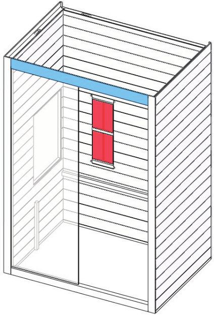
DE
TEILELISTE
Einzelteile der Kabine (Abweichungen möglich)
NR. NAME MENGE Kisten-Nr.
1 Rückwand (1860 x 1190 x 43 mm) 1 1
2 Seitenwand 1 (mit Bedienfeld, 1900 x 898 x 48 mm) 1 2
3 Seitenwand 2 (1900 x 898 x 48 mm) 1 2
4 Türquerleiste (unten, 1166 x 70 x 40 mm) 1 1
5 Frontglas (1759 x 597 x 6 mm) 1 4
6 Türquerleiste (oben, 1166 x 90 x 40 mm) 1 1
7 Deckenplatte (1268 x 888 x 28 mm) 1 3
8 Bankstützplatte (1188 x 450 x 33 mm) 1 3
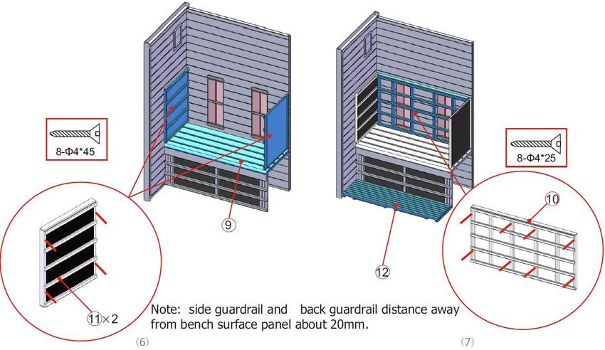
9 Bankoberflächenplatte (1188 x 500 x 33 mm) 1 1
10 Hinteres Schutzgitter (1122 x 661 x 54 mm) 1 1
11 Seitenschutzgitter (500 x 661 x 54 mm) 2 2
12 Bodenplatte (1186 x 320 x 50 mm) 1 1
13 Glastür (1725 x 572 x 6 mm) 1 4
14 Türgriff (außen: 300 x 40 x 45 mm; innen: 235 x 40 x 45 mm) 2 3
15 MDF-Abdeckung (1268 x 888 x 3 mm) 1 3
3/12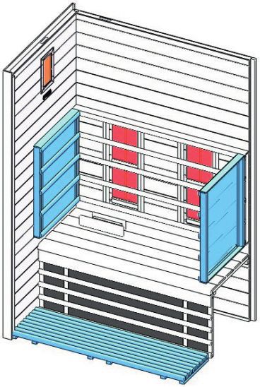
DE

Zubehörteile (Abweichungen möglich)

    Glas-Clip      Gummistreifen     Φ 4 x 45 Φ 4 x 25 Φ 4 x 12 Φ 6 x 60       Verbundschraube
      1 Stk.             4m          22 Stk.    8 Stk.       4 Stk.   2 Stk.         4 Stk.

MONTAGEANLEITUNG

Hinweise zur Montage
Entfernen Sie die Transportverpackung und prüfen Sie vor der Montage, ob die Infrarotkabine vollständig
und in einwandfreiem Zustand geliefert wurde.
Für die Montage der Kabine sind mindestens zwei Personen erforderlich.
Überprüfen Sie die Senkung und den Durchmesser der Bohrlöcher, um eine Beschädigung
des Holzes zu vermeiden.
Für die Installation ist eine Mindestraumhöhe von 2020 mm erforderlich.

Werkzeuge

                Schraubendreher                          Bandmaß
                                                                                         Bohrmaschine

                Spiralbohrer                             Hammer

                Inbus-Schlüssel                          Cutter                          Stehleiter

                Wasserwaage                              Bleistift

                                                                                                      4/12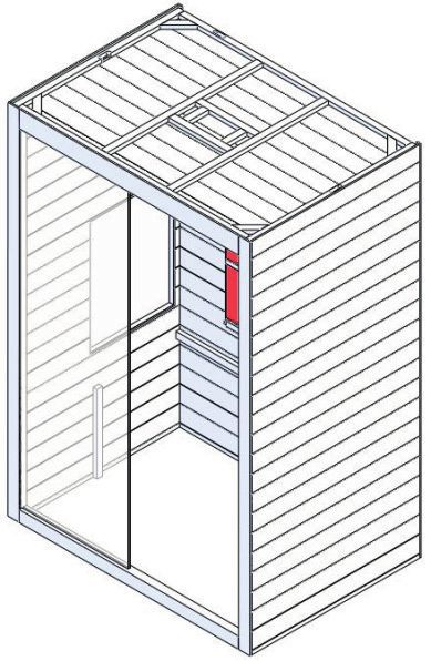
DE

MONTAGEANLEITUNG

Montageschritte

Hinweis:
Rückwand verfügt über Lüftungsschlitze.
5 cm Abstand zur nächsten Wand einhalten!

                                            5/12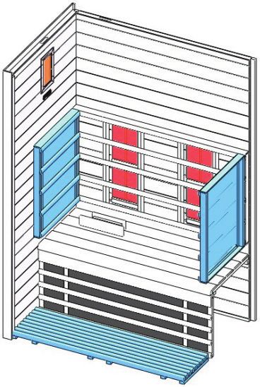
DE

MONTAGEANLEITUNG

Montageschritte

                              5 cm

                   Hinweis: S
                             chließen Sie die Kabel für die
                            Waden-Heizelemente an.

                                        2 cm

                                                               6/12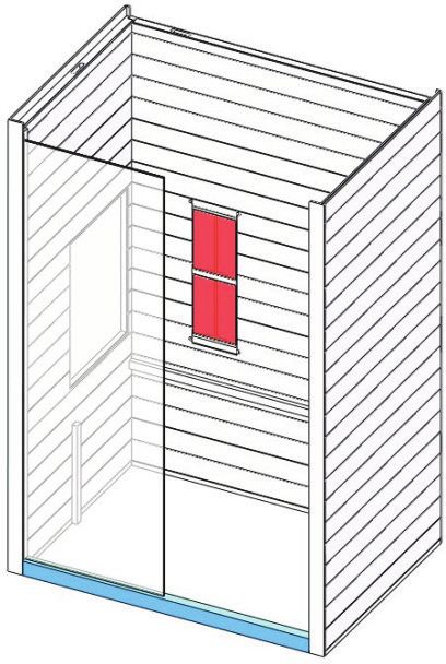
DE

MONTAGEANLEITUNG

Montageschritte

        Steuergerät

             Netzteil

                                                                                            Sechskant-
                                                                                            schraube
                                                                                          Scharnierun-
                                                                                          terteil
                                                            Scharnierober-             Gummidichtung
                                                            fläche
                                                                                Glastür
                                                                  Gummidichtung

          Glas-Clip
                                                                             Griff
                                                                             Glastür
                                                                             Griff
             Gummi-
             streifen                                             Holzabdeckung

              Hinweis: Schließen Sie alle Kabel auf dem Dach der Kabine an.

                                                                                                         7/12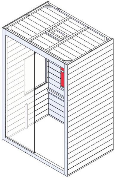
DE
BEDIENUNGSANLEITUNG
Verbinden Sie die Leistungseinheit mit der Wandsteckdose. Auf dem Display beginnt die LED-Anzeige zu blinken.
Nun können die Infrarotheizelemente, die Leuchte und die Musikfunktion eingeschaltet werden.

1) Inbetriebnahme
Drücken Sie auf    , um die Kabine einzuschalten. Die Heizelemente beginnen
zu heizen. Die Dauer wird automatisch auf 99 Minuten eingestellt und die
Lufttemperatur in der Kabine wird angezeigt. Wenn Sie erneut
auf     drücken, werden die Heizelemente ausgeschaltet.
Drücken Sie einzeln auf    ,    oder    , um die Intensität der Heizelemente an der
Vorderseite, der Rückseite bzw. für die Waden im Bereich 100–0 % einzustellen.

2) Temperatureinstellungen
Auf dem oberen Display wird die Lufttemperatur angezeigt. Wenn Sie
auf    drücken, können Sie die gewünschte Temperatur (35–60 °C) mithilfe der
Tasten    und     einstellen. Ist die Temperatur erreicht, werden die Heizelemente
automatisch abgeschaltet. Fällt die Temperatur um 4 °C unter die zuvor eingestellte
Temperatur, werden die Heizelemente automatisch wieder eingeschaltet.
Bitte beachten Sie Folgendes: Die in der Kabine maximal erreichbare
Temperatur kann niedriger als die gewünschte Temperatur sein. Dies ist
abhängig von der Temperatur außerhalb der Kabine. Standardmäßig ist eine Temperatur von
40 °C voreingestellt.

3) Zeiteinstellungen
Auf dem unteren Display wird die Dauer angezeigt. Wenn Sie auf      drücken, können Sie mit den
Tasten     /    die gewünschte Zeit (5–90 Minuten) einstellen. Die Minuten werden heruntergezählt.
Erreicht der Count-Down „00“, werden die Heizelemente automatisch ausgeschaltet.

4) Farblicht
Durch kurzes Drücken auf     können Sie die gewünschte Farbe (sieben Farben verfügbar) auswählen.
Durch langes Drücken auf     wechseln Sie zu einem automatischen Wechselmodus, in dem die Farbe
alle fünf Sekunden geändert wird.

5) Lüfter
Für den Lüfter können drei Modi eingestellt werden: automatisch, manuell, beenden. Der Automatikmodus
wird beim Einschalten der Heizelemente aktiviert. Im Automatikmodus wird der Lüfter eingeschaltet,
wenn die eingestellte Lufttemperatur in der Kabine erreicht wird.
Wenn Sie einmal auf      drücken, wird der manuelle Modus aktiviert und der Lüfter eingeschaltet.
Drücken Sie ein weiteres Mal auf die Taste, wird der Modus „beenden“ aktiviert und der Lüfter ausgeschaltet.

                                                                                                       8/12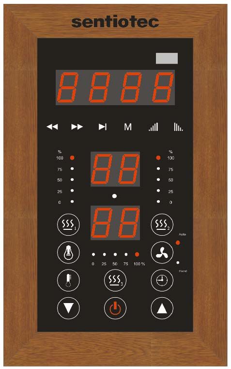
DE

6) MP3-Player
Wenn die Stromversorgung des MP3-Players eingeschaltet ist, drücken Sie lange auf die Taste „M“, um den
MP3-Player zu aktivieren. Wenn ein USB-Gerät angeschlossen ist, wird automatisch eine Datei von diesem
Gerät wiedergegeben. Andernfalls wird standardmäßig die Bluetooth-Funktion des MP3-Players aktiviert.
Schalten Sie anschließend die Bluetooth-Suchfunktion des Mobiltelefons ein und suchen Sie nach dem
Bluetooth-Gerät „FJF - BT“. Nach der erfolgreichen Verbindung mit dem Telefon kann der MP3-Player Musik
wiedergeben. (Hinweis: Jedes Mobiltelefon kann nur mit einem MP3-Player verbunden werden.) Drücken Sie
auf „    “, um die Wiedergabe anzuhalten.
Drücken Sie auf „     “ bzw. „       “, um den vorherigen bzw. nächsten Titel abzuspielen.
Halten Sie „    “ bzw. „     “ gedrückt, um die Lautstärke zu erhöhen bzw. zu verringern.
Der Lautstärkepegel kann im Bereich von 0 bis 32 geregelt werden.
Mit der Taste „M“ können Sie zwischen den Funktionen Bluetooth, MP3, externer Eingang und FM des MP3-
Players wechseln.
Wenn Sie die Funktion FM ausgewählt haben und lange auf die Taste „        “ drücken, sucht der MP3-Player
automatisch nach Sendern und speichert diese (Kanäle von 87,5 MHz bis 108,5 MHz). Drücken Sie nach
Beendigung der Suche auf „       “ bzw. „   “, gibt der MP3-Player den entsprechenden Sender wieder.

                                                                                                        9/12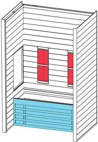
DE

SCHALTPLAN

  Eingangsspannung
                                                       Farbleuchte
  Leistung
  Nennstrom
  Sicherheitsstufe
     Modell

                        Lüfter     Temperaturfühler            Bedienfeld

                                            Netzteil

                     Steuergerät                          Antenne      Lautsprecher

                                                         Waden (Heizelement 3)

                                                         Vorderseite (Heizelement 1)

                                                         Rückseite (Heizelement 2)

                                                                                       10/12
DE
SERVICE
Gebrauchsanleitung
Trinken Sie viel Flüssigkeit vor und nach der Verwendung der Infrarotkabine.
Trocknen Sie sich vollständig ab.
Die optimale Kabinentemperatur für eine angenehme Sitzung liegt zwischen 35 und 40 °C.
Spätestens nach einer Heizzeit von einer Stunde sollte die Kabine ausgeschaltet und eine Heizpause von
mindestens 30 Minuten eingelegt werden.
Es wird empfohlen, nach der Nutzung warm zu duschen und sich zu entspannen.
Wartungsanleitung
Reinigen Sie die Kabine mit einem feuchten Baumwolltuch und trocknen Sie sie mit einem sauberen trockenen Tuch.
Reinigen Sie das Glas mit einem Fenster- oder Glasreiniger und einem weichen Tuch.
Es darf kein Wasser in das Bedienfeld fließen und das Bedienfeld darf nicht mit einem nassen Tuch
gereinigt werden. Verwenden Sie zum Reinigen ein Putztuch, das nur leicht mit einer milden Seifenlösung
(Geschirrspülmittel) befeuchtet ist.
Zur Reinigung der Kabine dürfen keine chemischen Reinigungsmittel verwendet werden.
Ziehen Sie die Schrauben der Bank alle drei Monate fest, um ein Lösen oder Abfallen zu verhindern.
Hinweis:
11/12DE
SERVICE
GARANTIEKARTE
Füllen Sie dieses Formular aus, fotografieren/scannen Sie es,
und senden Sie es per E-Mail an:
_____________________________________________
Kaufdatum:_____________________________________
Steuergerätetikett Seriennummer:__________________________________
Referenznummer:________________________________
Name:_________________________________________
Artikelzustand (ungeöffnet, vor Kurzem geöffnet
oder gebraucht)__________________________________
Kennzeichnen Sie in der folgenden Abbildung (mit einem Kreis),
welches Heizelement oder welche Platte fehlerhaft ist.
Fügen Sie Bilder des fehlerhaften Elements als Anhang hinzu,
und senden Sie sie per E-Mail.
400w 400w
250w 250w
340w
100w 100w
12/12User’s manual
EN
Infrared Cabin
VENUS VITAL
1/12
2018/4/23EN
PREFACE
Thank you very much for purchasing our product.
Please read this manual carefully before assembling and save it afterwards. Please write down the control box
serial number of the cabin as this number will be required in case of repair or order of spare parts.
ATTENTION
Installation and repair should only be done by a qualified electrician!
Check power supply rating and make sure the grounded outlet is correctly connected before installation.
Use original parts only. Do not share the outlet with any other appliances.
When not in use, turn off the cabin’s power unit.
Locate your cabin indoors and on a flat, level and dry surface.
DANGER
Heaters shall not be subjected to water spray; shower heads shall not be installed within the infrared cabin.
Covering the radiator causes a fire hazard due to overheating. Do not cover the heaters!
Keep flammable or easily combustible materials/objects (eg.towels) away from the radiator at all times.
Do not touch the radiator during and shortly after use as a burning hazard exists due to hot parts.
The light bulb heats in use. If the bulb needs to be changed, unplug the cabin and let the bulb cool down
before changing it.
Should the electrical connection get damaged, it must be replaced-either by the manufacturer or by
a licensed electrician!
WARNING
If you suffer from illness or other health-related problems, especially heart conditions or circulatory
disturbances or if you take medication, you should consult a doctor before using the infrared cabin.
Children and frail persons should never be in the cabin without supervision.
If you feel uncomfortable while using the infrared cabin, stop immediately and consult with your doctor.
Never go to a hot infrared cabin if you have taken alcohol, strong medicines or narcotics.
Technical data
Model Venus Vital
Cabin material Hemlock
Length 1286 mm
Width(depth) 907 mm
Height 1900 mm
Voltage 230 volt 50 Hz
Radiators Type Halogen radiators & carbon panel
Total output 1840 W 7.7A
Back panel 400 W x 2 (G220 halogen)
Front panel 250 W x 2 (carbon panel)
Calves 340 W x 1 (carbon panel)
Floor 100 W x 2 (carbon panel)
2/12EN
PARTS LIST
Cabin Individual parts (variations possible)
NO NAME Q’TY Box No
1 Back panel (1860*1190*43 mm) 1 1
2 Side panel 1 (w/control panel 1900*898*48 mm) 1 2
3 Side panel 2 (1900*898*48 mm) 1 2
4 Door cross bar (lower, 1166*70*40 mm) 1 1
5 Front glass (1759*597*6 mm) 1 4
6 Door cross bar (upper, 1166*90*40 mm) 1 1
7 Top panel (1268*888*28 mm) 1 3
8 Bench support panel (1188*450*33 mm) 1 3
9 Bench surface panel (1188*500*33 mm) 1 1
10 Back guardrail (1122*661*54 mm) 1 1
11 Side guardrail (500*661*54 mm) 2 2
12 Floor panel (1186*320*50 mm) 1 1
13 Glass door (1725*572*6 mm) 1 4
14 Door handle (outside, 300*40*45 mm & inside, 235*40*45 mm) 2 3
15 MDF cover (1268*888*3) 1 3
3/12EN
Hardware parts (variations possible)
Glass Clip Rubber strip Φ 4*45 Φ 4*25 Φ 4*12 Φ 6*60 Mixed Screw
1x 4m 22 x 8x 4x 2x 4x
ASSEMBLE INSTRUCTIONS
Assemble tips
Please remove transport packaging and inspect that your infrared cabin has been delivered complete and
intact before beginning assemble.
A least 2 persons are required for assemble of the cabin.
Please check the countersink and hole diameter of the drill holes to avoid damaging the wood.
The minimum room height required for installation is 2020 mm
Tools
Screwdriver Tape measure
Electric drill
Spiral drill Hammer
Allen Wrench Cutter Stepladder
Spirit level Pencil
4/12EN
ASSEMBLE INSTRUCTIONS
Assemble steps
Note: Back panel has ventilation slots.
Must keep 5 cm away from the next wall!
5/12EN
ASSEMBLE INSTRUCTIONS
Assemble steps
5 cm
Note: C
onnect the calves
heater cables.
2 cm
6/12EN
ASSEMBLE INSTRUCTIONS
Assemble steps
Control box
Power box
Hex screw
Hinge bottom
Hinge surface Rubber fitting
Glass door
Rubber fitting
Glass clip
Handle
Glass door
Handle
Rubber
Strip Wood cover
Note: connect all cables on the roof of the cabin
7/12EN
OPERATING INTRUCTIONS
Connect the power unit to wall outlet, the LED indicator will start to blink on the display.
Now it is possible to switch on the infrared heaters, the light and the music function.
1) Startup
Press to switch on the cabin and heaters start to work, the length of time is
automatically set to 99 minutes and the air temperature inside the cabin will be
displayed. Press again switch off the heaters.
Press / / separately to adjust the power intensity of front/back/calves
heaters from 100%-0%.
2) Temperature settings
The upper display refers to the air temperature. Press , you can set the desired
temperature (35-60°C) using the / keys. When at this temperature, the
heaters will stop working automatically; When it fall 4°C
below this temperature, the cabin will start up automatically.
Please note: The maximum air temperature reachable in the cabin may be
lower than the desired temperature. This is dependent on the temperature
outside the cabin.Default temperature=40°C.
3) Time settings
The lower display refers to the length of time. Press , you can set the desired time (5-90 mins) using the
/ keys. when count down to “00”, the heaters will shut off automatically.
4) Colour light
Short press , you can set the desired colour (7 colors totally); Long press to go into an automatically
cycling mode, changing colour every 5 seconds.
5) Fan
The fan has three modes: automatic, manual , close. The automatic mode is present when the heaters switch
on. In automatic mode, the fan switches on when the set cabin air temperature is reached.
Press once for manual mode, the fan switches on. Press once more for close mode, it switches off.
8/12EN
6) Mp3 player
In the condition of connecting electricity, long press “ M “, the MP3 player power on, (if the player is inserted
with a USB, it will acquiescently play USB file), otherwise, the MP3 player will turn on Bluetooth by default.
Then turn on the Bluetooth search function of mobile phone and search “FJF - BT” Bluetooth device. The MP3
player can play music after successfully connecting the phone (Note: each mobile phone just can connect one
MP3 player).
Press “ “ to pause playing. Press “ “, ” “ to play the previous/next song.
Press the “ “,” “key to adjust the volume plus or minus, the adjustment range is 0-32 level.
Press the “M” key, the MP3 player cycle Bluetooth-MP3-external input-FM function.
Long press “ “ in the FM state, the MP3 player search and save the channels automatically, (channels
from 87.5 MHZ to 108.5 MHZ).
After the searching finish, press” “ or “ ”,the MP3 player broadcast the stored channels.
9/12EN
CIRCUIT DIAGRAM
Input Voltage
Color light
Power Rating
Current Rating
Safety Grade
Model
Temperature
Fan Sensor Control panel
Power box
Control box Antenna Speaker
Calves (heater 3)
Front (heater 1)
Back (heater 2)
10/12EN
SERVICE
Use instructions
Drink plenty of liquids before and after use of the infrared cabin.
Dry yourself off completely.
The optimal cabin temperature for a pleasant session lies between 35 and 40°C.
After a heating period of an hour at the latest, the cabin should be switched off and a heating brake of
at least 30 minutes should be taken.
It is recommended to take a warm shower and relax after use.
Maintenance instructions
Clean the cabin with a damp cotton towel, dry with a clean dry towel.
Clean the glass with a window/glass cleaner and a soft cloth.
Do not pour water in the control panel or clean it with wet cloth. For cleaning purposes, use a cleaning cloth
that has been only slightly moistened with a mild soapy solvent (dish detergent).
Do not use chemical detergents to clean the cabin.
Please fasten the screws of the bench once every three months, avoid the loose or drop off.
Notes:
11/12EN
SERVICE
GUARANTEE CARD
Fill in this form and make a picture of it and Email to:
______________________________________________
Date of purchase:________________________________
Serial Number:__________________________________
Control unit label
Reference number:_______________________________
Name:_________________________________________
Article state (unopened, just opened or used):_________
Please encircle on picture below which heater or which panel
has a fault.
Attach pictures of the problem and send them through email.
400w 400w
250w 250w
340w
100w 100w
12/12Mode d’emploi
FR
Cabine infrarouge
VENUS VITAL
1/12
23.4.2018FR
INTRODUCTION
Merci d’avoir acheté notre produit.
Veuillez lire ce mode d’emploi avec attention avant le montage, puis le conserver. Veuillez noter le numéro
de série du boîtier de commande de la cabine, car ce numéro est requis en cas d’une réparation ou d’une
commande de pièces de rechange.
ATTENTION
L’installation et la réparation doivent toujours être effectuées par un électricien qualifié !
Contrôlez les caractéristiques de l’alimentation électrique et assurez-vous que la prise de terre est correctement
raccordée avant l’installation. Utilisez uniquement des pièces originales. N’utilisez pas d’autre appareils sur
la prise.
Lorsque vous ne l’utilisez pas, désactivez le bloc d’alimentation de la cabine.
Installez votre cabine à l’intérieur sur une surface plate, plane et sèche.
DANGER
Les radiateurs ne doivent pas être soumis à des projections d’eau ; ne pas installer de têtes de douche
dans la cabine infrarouge. Le fait de recouvrir le radiateur entraîne un risque d’incendie dû à une surchauffe.
Ne couvrez pas les radiateurs !
Maintenez toujours les matériaux/objets inflammables (par ex. serviettes) à l’écart du radiateur. Ne touchez
pas le radiateur pendant ou juste après son utilisation : les pièces chaudes risquent de causer des brûlures.
L’ampoule se réchauffe lorsqu’elle est allumée. Si l’ampoule doit être remplacée, débranchez la cabine et
laissez l’ampoule refroidir avant de la remplacer.
En cas d’endommagement du raccordement électrique, faites-le remettre en ordre par le fabricant ou un
électricien qualifié !
AVERTISSEMENT
Si vous souffrez d’une maladie ou d’autres problèmes de santé, en particulier de problèmes cardiaques
ou circulatoires, ou si vous prenez des médicaments, consultez un médecin avant d’utiliser une cabine
infrarouge. Les enfants et les personnes fragiles ne doivent jamais se tenir dans la cabine sans surveillance.
Si vous ressentez un malaise lors de l’utilisation de la cabine infrarouge, arrêtez immédiatement et consultez
votre médecin. N’entrez jamais dans une cabine infrarouge sous l’influence d’alcool, de médicaments
puissants ou de stupéfiants.
Données techniques
Modèle Venus Vital
Matériau de la cabine Pruche
Longueur 1286 mm
Largeur (profondeur) 907 mm
Hauteur 1900 mm
Tension 230 V 50 Hz
Radia- Type Radiateurs halogènes et panneau en carbone
teurs Puissance totale 1840 W 7,7 A
Panneau arrière 400 W x 2 (G220 halogène)
Panneau avant 250 W x 2 (panneau en carbone)
Mollets 340 W x 1 (panneau en carbone)
Sol 100 W x 2 (panneau en carbone)
2/12FR
LISTE DES PIÈCES
Pièces de la cabine (variations possibles)
N° NOM QTÉ N° boîtier
1 Panneau arrière (1860*1 190*43 mm) 1 1
2 Panneau latéral 1 (avec panneau de commande 1900*898*48 mm) 1 2
3 Panneau latéral 2 (1900*898*48 mm) 1 2
4 Traverse de porte (inférieure, 1166*70*40 mm) 1 1
5 Fenêtre avant (1759*597*6 mm) 1 4
6 Traverse de porte (supérieure, 1166*90*40 mm) 1 1
7 Panneau supérieur (1268*888*28 mm) 1 3
8 Panneau de support de banc (1188*450*33 mm) 1 3
9 Panneau de surface de banc (1188*500*33 mm) 1 1
10 Garde-corps arrière (1122*661*54 mm) 1 1
11 Garde-corps latéral (500*661*54 mm) 2 2
12 Panneau de sol (1186*320*50 mm) 1 1
13 Porte en verre (1725*572*6 mm) 1 4
14 Poignée de porte (extérieure, 300*40*45 mm & intérieure, 235*40*45 mm) 2 3
15 Couvercle MDF (1 268*888*3) 1 3
3/12FR
Matériel (variations possibles)
Clip pour vitre Bande en caoutchouc Φ 4*45 Φ 4*25 Φ 4*12 Φ 6*60 Vis de montage
1x 4m 22 x 8x 4x 2x 4x
INSTRUCTIONS DE MONTAGE
Conseils pour le montage
Veuillez retirer l’emballage de transport et vérifier que la cabine infrarouge a bien été livrée en état complet
et intacte avant de commencer le montage.
Au moins 2 personnes sont requises pour monter la cabine.
Veuillez contrôler le diamètre des fraisages et des perçages afin d’éviter d’endommager le bois.
Le lieu d’installation doit présenter une hauteur minimale de 2020 mm
Outils
Tournevis Ruban à mesurer
Perceuse électrique
Foret hélicoïdal Marteau
Clé Allen Cutter Escabeau
Niveau à bulle Crayon
4/12FR
INSTRUCTIONS DE MONTAGE
Étapes de montage
Remarque :
Les fentes de ventilation du panneau
arrière doivent se trouver au moins à
5 cm d’une autre paroi!
5/12FR
INSTRUCTIONS DE MONTAGE
Étapes de montage
5 cm
Note : r accordez le câble du
chauffage des mollets.
2 cm
6/12FR
INSTRUCTIONS DE MONTAGE
Étapes de montage
Boîtier de commande
Boîtier électrique
Vis hexagonale
Arrière de
charnière
Raccord en
Surface de caoutchouc
charnière
Porte en verre
Raccord en
caoutchouc
Clip de fixation
de verre
Poignée
Porte en verre
Poignée
Bande
en caout- Recouvrement en bois
chouc
Remarque : raccordez tous les câbles sur le toit de la cabine.
7/12FR
INSTRUCTIONS DE SERVICE
Raccordez le bloc d’alimentation à la prise murale, le voyant LED se met à clignoter sur l’écran.
Il est maintenant possible d’allumer les chauffages infrarouges, l’éclairage et la fonction musique.
1) Démarrage
Appuyez sur pour mettre la cabine en marche et allumer les chauffages. La durée est automatiquement
réglée sur 99 minutes, et la température
de l’air à l’intérieur de la cabine est affichée à l’écran. Appuyez à nouveau sur
pour désactiver les chauffages.
Appuyez sur / / séparément pour ajuster l’intensité
des chauffages avant/arrière/mollets de 100 % à 0 %.
2) Réglage de la température
L’affichage supérieur indique la température de l'air. Appuyez sur
pour régler la température souhaitée (35 à 60 °C) en utilisant les
touches / . Une fois cette température atteinte, les chauffages arrêtent de
fonctionner. Quand elle baisse de 4 °C,
la cabine se remet automatiquement en marche.
Remarque : la température d’air maximale pouvant être atteinte dans la
cabine peut être inférieure à la température souhaitée. Ceci dépend de la
température à l’extérieur de la cabine. La température par défaut est 40 °C.
3) Réglage de la durée
La partie inférieure de l’écran permet de régler la durée. Appuyez sur pour régler la durée souhaitée
(5 à 90 min.) en utilisant les touches / . Quand le décompte atteint « 00 », les chauffages se
désactivent automatiquement.
4) Éclairage
Appuyez brièvement sur pour régler la couleur souhaitée (7 couleurs au total). Appuyez longuement
sur pour passer en mode cycle automatique changeant de couleur toutes les 5 secondes.
5) Ventilateur
Le ventilateur dispose de trois modes : automatique, manuel, fermé. Le mode automatique est activé quand
les chauffages sont activés. En mode automatique, le ventilateur se met en marche quand la température
d’air réglée de la cabine est atteinte.
Appuyez une fois sur pour le mode manuel, le ventilateur se met en marche. Appuyez à nouveau pour
passer au mode fermé, il s’arrête.
8/12FR
6) Lecteur Mp3
Si la connexion électrique est établie, appuyez longtemps sur « M ». Le lecteur MP3 démarré, (si le lecteur
est branché a un disque U, il joue le fichier U), autrement, le lecteur MP3 fonctionne en mode Bluetooth par
défaut. Ensuite, activez la fonction de recherche Bluetooth de votre téléphone mobile et recherchez l’appareil
Bluetooth « FJF - BT ». Le lecteur MP3 peut jouer de la musique après avoir été connecté avec succès au
téléphone (note : chaque téléphone mobile peut se connecter à un seul lecteur MP3).
Appuyez sur « » pour interrompre la lecture.
Appuyez sur « », « » pour jouer le morceau précédent/suivant.
Appuyez sur la touche « » ou « » pour régler le volume sonore sur une plage de 0 à 32
Appuyez sur la touche « M » pour changer entre les fonctions Bluetooth, MP3, entrée externe et radio.
Appuyez longtemps sur « » en mode radio, le lecteur MP3 recherche et mémorise automatiquement les
stations (sur une bande de 87.5MHZ à 108.5MHZ).
Après avoir fini la recherche, appuyez sur « » et « » le lecteur MP3 joue les stations mémorisées.
9/12FR
SCHÉMA DE CÂBLAGE
Tension d’entrée
Éclairage coloré
Puissance nominale
Courant nominal
Niveau de sécurité
Modèle
Ventila-
Capteur de
teur
température Panneau de commande
électrique
Boîtier
Boîtier de
commande Antenne Enceinte
Mollets (chauffage 3)
Avant (chauffage 1)
Arrière (chauffage 2)
10/12FR
SERVICE
Instructions d’utilisation
Buvez beaucoup de liquide avant et après l’utilisation de la cabine infrarouge.
Séchez vous complètement.
La température optimale de la cabine pour une session agréable se trouve entre 35 et 40 °C.
Après la période de chauffe d’une heure au plus, la cabine doit être désactivée et le chauffage
interrompu pendant au moins 30 minutes.
Il est recommandé de prendre une douche chaude et de se détendre après l’utilisation.
Instructions de maintenance
Nettoyez la cabine avec une serviette en coton humide, séchez-la avec une serviette sèche propre.
Nettoyez le verre avec du produit pour vitres et un chiffon doux.
Ne faites pas couler d’eau sur le panneau de commande et ne le nettoyez pas avec un chiffon mouillé.
Pour le nettoyage, utilisez un chiffon propre légèrement humidifié avec un solvant savonneux doux
(produit à vaisselle).
N’utilisez pas de détergents chimiques pour nettoyer la cabine.
Resserrez les vis du banc tous les trois mois afin d’éviter qu’elles ne se desserrent ou tombent.
Remarques :
11/12FR
SERVICE
CARTE DE GARANTIE
Remplissez ce formulaire et photographiez-le.
Puis envoyez la photo par e-mail à :
_____________________________________________
Date d’achat :___________________________________
Étiquette de l’unité de commande Numéro de série :________________________________
Référence :_____________________________________
Nom :__________________________________________
État de l’article (pas ouvert, ouvert, ou utilisé) :________
Veuillez entourer sur la photo ci-dessous le chauffage
ou le panneau défectueux.
Joignez des photos du problème et envoyez-les par e-mail.
400w 400w
250w 250w
340w
100w 100w
12/12Sie können auch lesen