BESCHREIBUNG: Icom Europe
←
→
Transkription von Seiteninhalten
Wenn Ihr Browser die Seite nicht korrekt rendert, bitte, lesen Sie den Inhalt der Seite unten
BESCHREIBUNG:
Die AL-705 ist eine
magnetische Loop-Antenne
für 40 m bis 10 m (7 MHz bis
29,7 MHz) mit 20 W PEP bei
SSB-Betrieb bzw. 10 W bei
CW- und Digitalbetrieb.
Aufbauanleitung
WARNUNG! Niemals die inneren oder äußeren Koaxialkabel der AL-705 als Überbrückung
verwenden!
Loop-Antenne zusammenbauen Geräte anschließen
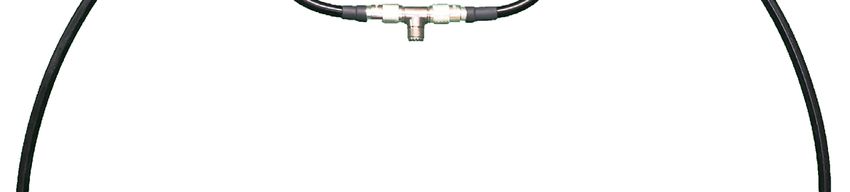
1) Die PL-259-Stecker des äußeren Den PL-259-Stecker der Anschlussleitung mit der
Schleifenelements an die SO-239-Buchse des T-Stücks in der Mitte des kleinen
SO-239-Buchsen der schwarzen Schleifenelements und das andere Ende mit dem
Abstimmbox schrauben. Funkgerät verbinden.
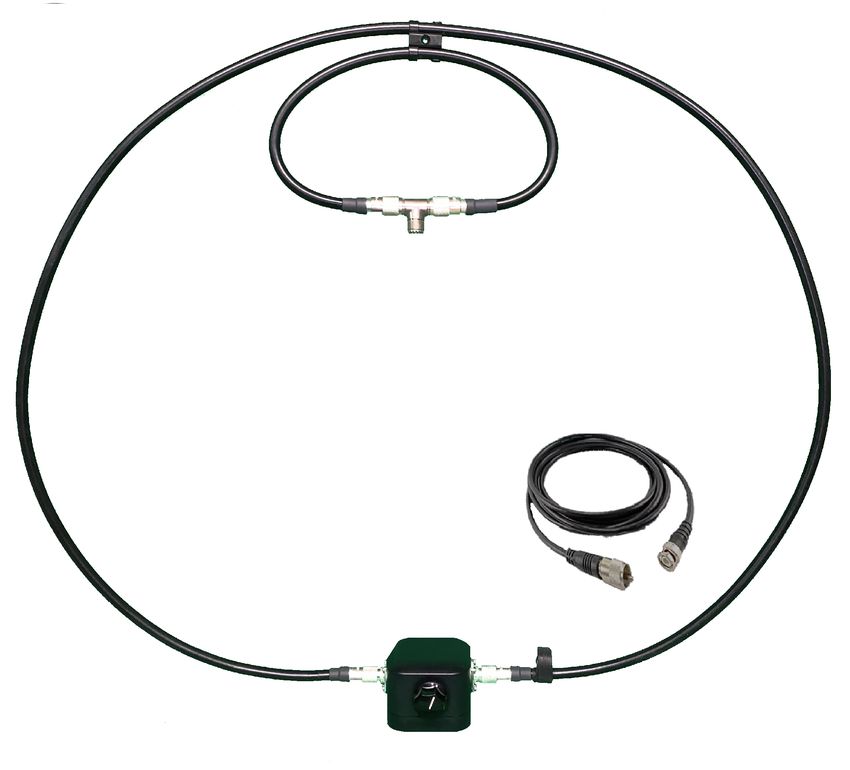
2) Das innere Schleifenelement Einstellung der Mikrofonverstärkung
mithilfe des mitgelieferten Nylon-
clips etwa mittig am äußeren Für alle alle Sprachmodi sollte die Mikrofonverstärkung
Schleifenfenelement befestigen. des Funkgeräts so eingestellt werden, dass beim Spre-
chen der Maximalpegel der Austeuerungsanzeige nicht
erreicht wird, was normalerweise bei einer Einstellung
zwischen 9 und 11 der Fall ist. So verhindert man eine
Störung der Sprachübertragung durch Übersteuerung.
WAHL DES AUFSTELLORTS UND BETRIEB

1) Die Abstimmbox darf nicht auf eine Metallfläche gestellt werden. Außerdem muss die Loop-Antenne einen Abstand von
   mindestens 50 cm zu Metallgegenständen haben.
2) Platzieren Sie die Loop-Antenne in einer Höhe, die größer als ein Schleifendurchmesser ist, also etwa 1 m.
3) Werden Senden und Empfang durch Objekte im Sichtfeld der Antenne behindert, kann man sie erhöht anbringen.
4) Alle Antennen unterliegen physikalischen Beeinflussungen durch ihre Umgebung. Diese sind auch bei der Wahl der
   Betriebsposition zu berücksichtigen. Erwarten Sie z.B. von einer Loop-Antenne in Innenräumen nicht die gleiche
   Performance wie im Freien. Ebenso wird eine Antenne in größerer Höhe oft eine bessere Leistung erbringen, da ihr
   Sichtfeld nicht beeinträchtigt wird.
5) Bei der Installation in Häusern, deren Dächer mit Asphaltschindeln gedeckt sind, entsteht typischerweise ein Verlust
   von etwas mehr als einer S-Stufe, im Normalfall aber nicht mehr als 1,75 S-Stufen.
6) Wird die Antenne in Gebäuden installiert, deren Außenwände z.B. mit Metallgittern als Putzträger oder mit
   Aluminiumverkleidungen versehen sind, ist eine ordnungsgemäße Funktion nahezu unmöglich. Wenn es keine
   andere Möglichkeit zur Aufstellung der Antenne gibt, dann stellen Sie sie vor das größte Fenster und entfernen Sie
   alle Metallabdeckungen in der Umgebung.
7) Die Abstrahlung im Nahfeld der Loop-Antenne erfolgt hauptsächlich in der Ebene der Schleife, nicht im Zentrum. Die
   Veränderung der Ausrichtung des Schleifenzentrums zu einer Störquelle kann jedoch dazu beitragen, durch elek-
   tronische Geräte verursachte Störungen zu eliminieren.
8) Die Fernfeld-Abstrahlung der Loop-Antenne erfolgt ebenfalls hauptsächlich in der Ebene der Schleife, sie kann aller-
   dings durch Metallstrukturen in der Umgebung verändert werden, wodurch die Richtcharakteristik der Antenne negativ
   beeinflusst wird.

ABSTIMMHINWEISE

Die Antenne AL-705 verfügt über einen Abstimmknopf am Alpha-Match-Anpassungsglied. Mit diesem schwarzen Dreh-
knopf ist die Antenne auf das niedrigste SWR von 2,5:1 oder weniger auf 10 m bis 40 m abzustimmen.
HINWEIS: Es ist einfacher, die Anpassung und Abstimmung der Loop-Antenne auf 40 m auszuprobieren. Die folgende
Vorgehensweise hat sich in fast allen Situationen als einfachste Methode zur Abstimmung der AL-705 erwiesen:

ABSTIMMEN
1) Nachdem das Koaxialkabel mit dem Funkgerät verbunden wurde, ist die minimale Sendeleistung zu wählen.
2) Den SSB-Modus aufrufen und die Lautstärke am Funkgerät einstellen. Dann den Drehknopf an der Abstimmbox
   drehen und dabei auf den lautesten Rauschpegel achten.
3) Anschließend kann mit dem Drehknopf an der Abstimmbox die Feinabstimmung vorgenommen werden.
   Das SWR-Meter des Funkgeräts oder eines Antennenanalysators sollte einen möglichst geringen S-Wert anzeigen.

HINWEISE
(Verstimmen durch Handkapazität)
Um die Handkapazität während des Abstimmens auszugleichen, kann das sogenannte „Reverse Tuning“-Abstimm-
verfahren Anwendung finden. Während eine Hand den Drehknopf an der Abstimmbox berührt, stellt man das minimale
SWR ein, z.B. 1,9:1. Entfernt man nun die Hand, wird ein SWR von z.B. 4,3:1 angezeigt. Stellt man anschließend
ein SWR von 4,3:1 ein, während die Hand den Drehknopf berührt, erreicht man ein SWR von 1,9:1, wenn die Hand weg-
genommen wird.

(Abstimmen mit Messgerät, ohne Berührung der Antenne)
Nachdem die Schritte 1) und 2) unter „ABSTIMMEN“ durchgeführt wurden, lässt sich mit einem Antennenanalysator oder
einem SWR-Messgerät (intern oder extern) das niedrigste SWR ermitteln, ohne die Antenne zu berühren. Während man
das SWR auf dem Messgerät beobachtet, ändert man die Frequenz am Funkgerät oder dem Analysator bis das Messge-
rät das niedrigste SWR anzeigt.
DESCRIPTION
                                                             The AL-705 is a HF 40 to 10
                                                             meter (7 - 29.7 MHz)
                                                             Magnetic Loop antenna that
                                                             is rated at 20W PEP SSB,
                                                             10W CW & Digital.

                                                                         Assembly Instructions

WARNING - Never use the Inner or Outer Coaxial cables of the AL-705 as a jumper coax.

Assemble the Loop                         Connect your equipment

1) Attach the Outer Loop                  Attach the feedline's PL259 to the SO239 on the
Element to the black match                T-Connector in the center or the (small) coupling
box by screwing the PL-259                loop, then connect the other end of the feedline to
connectors on the Outer Loop              your equipment.
into the SO-239 connectors on
the match.
                                          Make adjustments to your Mic Gain settings
2) Attach the Inner Loop using
the included Nylon clip to the            For all voice modes, adjust your equipment's Mic
approximate center of the                 Gain so your meter does not peak when
Outer Loop Element.                       speaking, which will typically be a setting between
                                          9 and 11. This will ensure you do not have a
                                          distorted voice transmission by keeping the
                                          antenna and equipment from being overdriven.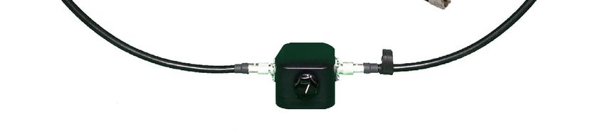
SITE SELECTION AND OPERATION

1) Do not place the tuning box on a metal surface. Also, keep the loop at least 18 inches from metal objects.
2) Place the loop greater than 1 loop diameter high (about 3 feet or higher).
3) The loop can be placed higher, so it can see above and past obstacles.
4) All antennas are affected by the physical environment that surrounds them. For maximum performance, best practice
for antenna placement should be considered when placing the loop in its’ operating position. For example, do not expect
the same performance from the loop when indoors as you are experiencing on another antenna that is outside. Similarly,
an antenna placed at 12 feet, while your loop might be setting at a height of 3 feet, will often perform better as it can see
above and past obstacles.
5) In home installations where the roof is composed of asphalt shingles, you will typically see a little more than 1 S-Unit of
loss, but usually no more than 1.75 S-Units of loss.
6) In home installations where the exterior walls have a chicken type wire under stucco or aluminum siding makes it nearly
impossible for any antenna to function properly. If you are forced to operate in this situation, then place the antenna in
front of the largest window, after removing any metal screen.
7) Near field radiation patterns of a magnetic loop are mainly in the plain of the loop, not through the center. Facing the
center of the loop at a noise source can, however, help to null out interference caused by noisy electronics.
8) Far field radiation patterns of a magnetic loop are mainly in the plain of the loop, however, the surrounding environment
can affect radiation patterns, which may naturally begin to overlap. This effect can minimize the far field directionality of a
loop.

TUNING TIPS

The AL-705 antenna has a built-in tuning knob on the Alpha Match. It is with this black knob that you tune the antenna to
the lowest SWR of 2.5:1 or less 10-40 meters. NOTE – It is easier to match and learn to tune the loop on 40 meters. The
following technique has proven to be the easiest method for tuning the AL-705 in nearly all scenarios:

TUNING
1) After attaching your coax to your radio, set your radio for minimum power output.
2) Set your rig to SSB Mode, turn the volume up, and listen for the loudest noise floor as you turn the black knob on the
match to the right.
3) You can then fine tune the Alpha Match with the black knob till the SWR meter on your rig’s internal meter or your
antenna analyzer is as low as possible.

TUNING TIPS
(Offset frequency while tuning for hand capacitance)
a. To off-set the effect of hand capacitance while tuning, a technique called reverse tuning can be used. To reverse tune a
magnetic loop, tune for minimum SWR while touching the Black Knob on the Alpha Match, say 1.9:1; and then when you
remove your hand you might see 4.3:1 for example. Then all you must do is tune for 4.3:1 while your hand is on the knob
to achieve an SWR of 1.9:1 when you remove your hand.

(Tuning with equipment, without touching the antenna)
a. An antenna analyzer or SWR meter (whether internal to the rig or inline) can be used to find the lowest SWR after step
1 & 2 under TUNING is performed. This can be done without you having to touch the antenna. While watching the SWR
on your equipment, change the frequency on your rig or analyzer till minimum SWR is shown on the meter.
DESCRIPCIÓN
                                                                La AL-705 es una antena de
                                                                Bucle Magnético de HF de
                                                                40 a 10 metros (7 - 29.7
                                                                MHz) catalogada a 20W PEP
                                                                SSB, 10W CW y Digital.

                                                                               Instrucciones de Montaje

ADVERTENCIA – Nunca utilice los cables coaxiales Interno o Externo del IC-705 como puente coaxial.

Montaje del Bucle                            Conecte su equipo

1) Conecte el Elemento del                   Conecte la línea de alimentación PL259 al SO239
Bucle Exterior a la caja negra               situado en el Conector T en el centro del bucle de
atornillando los conectores                  acoplamiento (pequeño), a continuación conecte
PL-259 del Bucle Exterior en                 el otro extremo de la línea de alimentación al
los conectores SO-239                        equipo.
situados en la caja.
                                             Realice los ajustes en la configuración del Mic Gain
2) Conecte el Bucle Interior
aproximadamente en el centro                 Para todos los modos de voz : configure el Mic
del Bucle Exterior utilizando el             Gain de su equipo para que el medidor no
clip de Nailon suministrado .                alcance picos al hablar, ese ajuste se sitúa
                                             normalmente entre el nivel 9 y 11. Esto asegurará
                                             una transmisión de voz no distorsionada al evitar
                                             que la antena y el equipo se sobrecarguen.
SELECCIÓN Y FUNCIONAMIENTO DEL SITIO 1) No coloque la caja de sintonización en una superficie metálica. Además, mantenga el bucle al menos a 18 pulgadas de objetos metálicos. 2) Coloque el bucle a más de una altura de diámetro del bucle grande (aproximadamente 3 pies o más alto). 3) El bucle se puede colocar más alto, de tal forma que pueda sobrepasar de los obstáculos. 4) Todas las antenas se ven afectadas por el entorno físico. Para un máximo rendimiento de la antena deberé tener en cuenta la ubicación al colocar el bucle en su posición de operación. Por ejemplo, no espere el mismo rendimiento del bucle cuando esté dentro de casa al de otra antena que se encuentra en el exterior. De igual modo, una antena colocada a 12 pies, mientras su bucle solo está colocado a una altura de 3 pies, funcionará a menudo mejor al poder ver por encima de los obstáculos circundantes. 5) En las instalaciones de interior cuando el techo está compuesto de tejas de asfalto, probablemente apreciará una pequeña pérdida de 1 unidad S, pero normalmente no más de 1.75 unidades S. 6) En las instalaciones de interior, cuando las paredes exteriores tienen bajo el estuco una alambrada o están revestidas de aluminio el buen funcionamiento de cualquier antena se vuelve casi imposible. Si está obligado a funcionar en estas condiciones, coloque la antena en frente de la ventana más grande, tras retirar cualquier pantalla metálica. 7) Los patrones de campos de radiación cercanos de un bucle magnético se encuentran principalmente en el bucle, no a través del centro. Sin embargo, colocar el centro del bucle en una fuente de ruido puede ayudar a anular la interferencia causada por una electrónica ruidosa. 8) Los patrones de campos de radiación lejanos de un bucle magnético se encuentran principalmente en el bucle, sin embargo, el entorno circundante puede afectar los patrones de radiación, que naturalmente pueden comenzar a superponerse. Este efecto puede minimizar la direccionalidad de los campos lejanos de un bucle. CONSEJOS DE SINTONIZACIÓN La antena AL-705 incorpora de serie un botón de sintonización en el Alpha Match. Es con este botón con el que puede sintonizar la antena al más bajo SWR de 2.5:1 o menos de 10-40 metros. NOTA – Es más sencillo acoplar y aprender a sintonizar el bucle en 40 metros. La siguiente técnica ha demostrado ser el método más sencillo para sintonizar la AL-705 en casi todos los escenarios : SINTONIZAR 1) Tras conectar el cable coaxial a su radio, configure la radio para una salida mínima. 2) Ponga su equipo en Modo SSB, suba el volumen y escuche el ruido de fondo más fuerte mientras gira el botón negro de acoplamiento hacia la derecha. 3) Entonces podrá afinar la sintonización del Alpha Match a través del botón negro hasta que el medidor SWR en el medidor interno de su equipo o su analizador de antena esté lo más bajo posible. CONSEJOS DE SINTONIZACIÓN (Frecuencia de desplazamiento al sintonizar capacitancia manual) a. Para compensar el efecto de la capacitancia manual durante la sintonización, se puede utilizar una técnica llamada sintonización inversa. Para invertir la sintonización de un bucle magnético, sintonice la SWR mínima mientras toca el botón negro en el Alpha Match, por ejemplo 1.9: 1; y luego, cuando quita la mano, puede ver 4.3: 1. A continuación, lo único que deberá hacer es sintonizar 4.3: 1 mientras su mano está en el botón para lograr una SWR de 1.9: 1 al retirar su mano. (Sintonización con el equipo, sin tocar la antena) a. Se puede utilizar un analizador de antena o un medidor de SWR (ya sea interno al equipo o en línea) para encontrar la SWR más baja después de realizar los pasos 1 y 2 de “SINTONIZAR”. Esto se puede hacer sin necesidad de tocar la antena. Mientras observa el SWR en su equipo, cambie la frecuencia en su equipo o analizador hasta que se muestre el SWR mínimo.
OPIS
                                                          AL-705 to magnetyczna
                                                          antena pętlowa KF (7-29,7
                                                          MHz) o mocy 20 W PEP dla
                                                          SSB i 10 W dla CW/Digital.

                                                                        Instrukcja montażu.

UWAGA – Nigdy nie używaj wewnętrznych ani zewnętrznych kabli koncentrycznych AL-705 jako
zworek.

Złóż pętlę.                             Podłącz swój sprzęt.

1) Przymocuj zewnętrzny element         Podłącz kabel antenowy zakończony złączem
pętli do czarnej obudowy poprzez        PL-259 do gniazda SO-239 znajdującego się na
przykręcenie go za pomocą               trójniku małej pętli, a następnie podłącz drugi
złącza PL-259 do gniazda                koniec kabla antenowego do sprzętu.
SO-239.
                                        Dostosuj ustawienia Mic Gain.
2) Przymocuj pętlę wewnętrzną za
pomocą dołączonego klipsa               Dla wszystkich trybów głosowych dostosuj Mic
nylonowego do przybliżonego             Gain swojego sprzętu, tak aby miernik nie osiągał
środka elementu pętli                   szczytowych wskazań podczas mówienia, co
zewnętrznej.                            zwykle będzie ustawieniem między 9 a 11.
                                        Zapewni to brak zniekształconej transmisji głosu,
                                        zapobiegając przesterowaniu anteny i sprzętu.
WYBÓR MIEJSCA I PRACA 1) Nie umieszczaj tuner’a na metalowej powierzchni. Ponadto, trzymaj pętlę co najmniej 0,5 m od metalowych przedmiotów. 2) Umieść pętlę na wysokości większej niż 1 średnica pętli (około 1 m lub wyżej). 3) Pętlę można umieścić wyżej, aby pracowała nad i za przeszkodami. 4) Otoczenie ma wpływ na pracę anteny. Aby uzyskać maksymalną wydajność, podczas ustawiania anteny w pozycji roboczej należy wziąć pod uwagę najlepsze praktyki dotyczące umieszczania anteny. Na przykład nie spodziewaj się takiej samej wydajności pętli w pomieszczeniu, jak na innej antenie znajdującej się na zewnątrz. Podobnie antena umieszczona na wysokości 4 m, podczas gdy pętla jest ustawona na wysokości 1 m, często będzie działać lepiej, ponieważ może pracować nad i za przeszkodami. 5) W instalacjach domowych, w których dach składa się z gontów asfaltowych, zazwyczaj można zaobserwować nieco więcej niż 1 S-Unit straty, ale zwykle nie więcej niż 1,75 S-Unit straty. 6) W instalacjach domowych, w których ściany zewnętrzne mają drut typu kurczak pod tynkiem lub okładzinę aluminiową, prawie niemożliwe jest prawidłowe działanie jakiejkolwiek anteny. Jeżeli jesteś zmuszony do pracy w takim środowisku, umieść antenę przed największym oknem po uprzednim zdjęciu metalowego ekranu. 7) Charakterystyka promieniowania pola magnetycznego pętli magnetycznej przebiega głównie na płaszczyźnie pętli, a nie w jej środku. Jednak skierowanie środka pętli na źródło szumów może pomóc w wyeliminowaniu zakłóceń powodowanych przez inne urządzenia elektroniczne. 8) Promieniowanie pola dalekiego w pętli magnetycznej występuje głównie na płaszczyźnie pętli, jednak otaczające środowisko może wpływać na wzorce promieniowania, które mogą naturalnie zacząć się nakładać. Efekt ten może zminimalizować kierunkowość pola dalekiego pętli. WSKAZÓWKI DOTYCZĄCE STROJENIA Antena AL-705 ma wbudowane pokrętło strojenia. Za pomocą tego czarnego pokrętła dostrajasz antenę do najniższego SWR 2,5:1 lub mniej 10-40 metrów. UWAGA – łatwiej jest dopasować i nauczyć się stroić pętlę na 40 metrach. Poniższa technika okazała się najłatwiejszą metodą dostrojenia AL-705 w prawie wszystkich scenariuszach: STROJENIE 1) Po podłączeniu kabla koncentrycznego do radia, ustaw radio na minimalną moc wyjściową. 2) Ustaw swój zestaw na tryb SSB, zwiększ głośność i słuchaj najgłośniejszego szumu, obracając czarne pokrętło strojenia anteny w prawo. 3) Następnie możesz precyzyjnie dostroić antenę za pomocą czarnego pokrętła, aż wskaźnik SWR na wewnętrznym mierniku Twojego sprzętu lub analizatorze anteny będzie tak nisko, jak to możliwe. WSKAZÓWKI DOTYCZĄCE STROJENIA (Eliminacja zakłóceń spowodowanych pojemnością dłoni) a. Aby zniwelować efekt spowodowany przez dotykanie anteny podczas strojenia, można zastosować technikę zwaną strojeniem odwrotnym. Aby odwrócić strojenie pętli magnetycznej, ustaw minimalny SWR dotykając czarnego pokrętła anteny do powiedzmy 1,9:1, a potem kiedy puścisz pokrętło, możesz zobaczyć na przykład 4,3:1. Następnie wystarczy nastroić antenę na 4,3:1 dotykając pokrętła, aby uzyskać 1,9:1 po puszczeniu czarnego pokrętła. (Strojenie bez dotykania anteny) b. Analizator antenowy lub miernik SWR (wewnętrzny lub wbudowany) może być użyty do znalezienia najniższego SWR po wykonaniu kroku 1 i 2 w sekcji STROJENIE. Można to zrobić bez konieczności dotykania anteny. Obserwując wartość SWR na mierniku, zmień częstotliwość na swoim zestawie albo analizatorze, aż na mierniku pojawi się minimalny SWR.
ANTENNA LOOP MAGNETICA ICOM AL-705

                                                                             DESCRIZIONE
                                                                             La antenna AL-705 Opera in
                                                                             HF dai 40 ai 10 metri
                                                                              (7 - 29.7 MHz)
                                                                             con una Potenza MAX di
                                                                             20W PEP SSB, 10W CW &
                                                                             Digital.

                                                                                           Istruzioni di montaggio
            ATTENZIONE – Non usare mai I Loop coassiali come cavo per il collegamento alla radio.

            Assemblare la antenna Loop                    Come collegare la radio al Loop

            1) Collegare l’elemento del                   Collegare il cavo cossiale della linea di
            Loop esterno alla scatola di                  alimentazione all’SO239 su connettore a T
            accord near, avvitando I                      posizionato nel Loop piccolo. Quindi collegare
            connettori PL-259 sul Loop                    l’altro estremo del cavo allo IC705
            esterno.
                                                          Modifica I settaggi del guadagno nicrofonico
            2) Attaccare il Loop interno                  Per tutti I modi operativi, regola il Guadagno
            utilizzando la clip in nylon a                microfonico in maniera da non saturare e
            corredo, posizionandola                       distorcere in uscita. Regola l’emissione nel valore
            approssimativamente nel                       intorno ai 9-11 di picco.
            centro dell’anello esterno.                   In questo modo lavorerai ottimamente, senza
                                                          sovracaricare la antenna.

COME UTILIZZARE LA LOOP MAGNETICA

1) Non posizionare la scatola di sintonia su superfici metalliche. Tenere la Loop ad una distanza di 50cm da superfici
metalliche.
2) Posizionare la base del Loop alla distanza minima di un metro da terra
3) Posizionare la Loop al di sopra di ostacoli per una migliore operatività in TX e RX.
4) Tutte le antenne sono influenzate dall’ambiente circostante. Per avere le massima prestazione, è necessario prendere
in considerazione quale pratica adottare a secondo dell’ambiente di utilizzo. Non possiamo pretendere le stesse
prestazioni usando l’antenna in casa fra quattro mura ed una antenna posizionata sul tetto di casa. L’antenna più alta,
superando gli ostacoli avrà sempre un rendimento migliore.
5) Utilizzando l’antenna in casa noterai una soglia di rumore più alta del solito di circa 1, 1.7 di livello, questo è normale, dovuto alla costruzione in cemento, metallo e cavi elettrici che ti circondano. 6) Quando utilizzi l’antenna in casa, a causa dei muri che ti ostacolano ed attenuano la ricezione e trasmissione, troverai più efficace posizionare la LOOP vicino alla finestra più grande della casa, con buoni risultati . 7) Quando operi con la tua antenna, cerca di stare lontano da altre sorgenti elettromagnatiche, in modo da non risentire del campo magnetico generato. 8) I modelli di radiazione di campo elettromagnetico, si trovano principalmente alla base di un circuito, tuttavia l’ambiente circostante può influenzare il campo elettromagnetico della tua antenna sovrapponendosi, questo effetto può ridurre al minimo la direzionalità della LOOP. CONSIGLI DI UTILIZZO La antenna AL-705 ha una manopola di sintonia sulla scatola “Alpha Match”. E’ con questa manopola near che si sintonizza l’antenna sulla frequenza desiderata portandola all’SWR di 2.5:1 o inferiore dai 10 ai 40 metri. NOTA – La taratura/sintonia dell’antenna LOOP è semplice e veloce dai 40m ai 10m SINTONIA 1) Dopo avere collegato con il cavo coassiale la antenna alla radio, regola la potenza di trasmissione al minimo. 2) Imposta la radio in SSB, alza il volume ed ascolta il rumore di fondo , regolando con la manopola near della LOOP sino al rumore di fondo massimo. 3) Ruotando la manopola “Alpha Match” sintonizzati sino ad avere il migliore SWR . Troverai comoda la lettura SWR in tempo reale dell’IC-705. CONSIGLI DI SINTONIA (Frequenza di Offset durante la sintonia manuale) Per compensare l’effetto della capacità della mano durante l’accordo, è possible utilizzare una tecnica chiamata accordatura inversa. Per eseguire l’accordo inverso di una LOOP magnetica, sintonizza per un SWR minimo ad esempio 1.9:1, poi leva la mano dalla manopola e potresti avere un SWR di 3.4:1 per esempio. Quindi quello che devi fare è accordare per 4.3:1 con la tua mano sulla manopola, per ottenere un SWR di 1.9:1 quando rimuovi la mano. (Sintonizzazione senza toccare l’ antenna) E’ possible utilizzare un analizzatore di antenna o un misuratore di SWR ( sia interno alla radio o in linea ) per trovare l’SWR più basso dopo avere eseguito I passaggi 1 e 2 in sintonia. Questa operazione puoi farla senza toccare l’antenna Mentre osservi l’SWR sullo strumento, modifica la frequenza sino ad avere l’ SWR migliore.
Sie können auch lesen