Typ 5030 Betriebsanleitung Manuel d'utilisation - Operating Instructions - Schubert & Salzer Control Systems
←
→
Transkription von Seiteninhalten
Wenn Ihr Browser die Seite nicht korrekt rendert, bitte, lesen Sie den Inhalt der Seite unten
Betriebsanleitung

                    Operating Instructions

                    Manuel d'utilisation

                     Typ 5030

Version: 02/2021
                        Bunsenstrasse 38          D-85053 Ingolstadt
M5030-def.doc           Tel: (0841) 9654-0        Fax: (0841) 9654-590
Art.-Nr.: 1105030       www.schubert-salzer.com
Inhalt/Content/Sommaire

1.     1 .....................................................................................        Betriebsanleitung (deutsch)     3
1.1           Ersatzteilliste Baureihe SPV1                                                                                     3
1.2           Technische Daten                                                                                                  4
1.3           Einbau                                                                                                            6
1.4           Explosionsschutz nach ATEX 2014/34/EU                                                                             7
1.5           Öffnen der Antriebshaube                                                                                          8
1.6           Elektrischer Anschluss                                                                                            9
1.7           Adaption des Antriebs                                                                                             12
1.8           Störmeldeausgang                                                                                                  14
1.9           Kommunikationssoftware                                                                                            15
1.10          Handbetätigung                                                                                                    16
1.11          Demontage und Montage des Antriebes                                                                               17
1.12          Demontage und Montage der Funktionseinheit / Ventilunterteil                                                      18
1.13          Entsorgung                                                                                                        20
2.     2 ..............................................................                          Operating Instructions (Englisch)    21
2.1           SPV1 Series spare parts list                                                                                      21
2.2           Technical data                                                                                                    22
2.3           Installation                                                                                                      23
2.4           Explosion protection according to ATEX 2014/34/EU                                                                 24
2.5           Opening the cover of the actuator                                                                                 25
2.6           Connection to Electricity Supply                                                                                  26
2.7           Adaption of actuator                                                                                              29
2.8           Error signal output                                                                                               31
2.9           Communication software                                                                                            32
2.10          Manual actuation                                                                                                  33
2.11          Disassembly and assembly of the actuator                                                                          34
2.12          Disassembly and assembly of function unit / lower part                                                            35
2.13          Lubrication and bonding plan                                                                                      37
3.     3 .................................................................................          Manuel d‘utilisation (français)   38
3.1           Liste des pièces de rechange Série SPV1                                                                           38
3.2           Informations techniques                                                                                           39
3.3           Installation                                                                                                      41
3.4           Protection antidéflagrante selon ATEX 2014/34/UE                                                                  42
3.5           Ouverture du capot de l‘actionneur                                                                                43
3.6           Raccordement électrique                                                                                           44
3.7           Adaptation de l’actionneur                                                                                        47
3.8           Sortie signalisation de défaut                                                                                    49
3.9           Logiciel de communication                                                                                         50
3.10          Commande manuelle                                                                                                 51
3.11          Démontage et montage de l’actionneur                                                                              52
3.12          Démontage et montage de l’unité fonctionnelle / Composants vanne                                                  53

                                                                                   -2–
1         Betriebsanleitung (deutsch)

1.1       Ersatzteilliste Baureihe SPV1

              (Nur Original Ersatzteile von Schubert & Salzer Control Systems verwenden!)

                                                                   El.Antrieb

                                                    Kontermutter   34

                                                                   Säule 27
                                                                   Stellschraube 26
                                                                   Zyl.Schraube 25
                                                                   Flansch f. Säule 24
                                                                   Mutter f. Säule 28

                                   Anpressring 22
                                   Packung 23
                                   Anpressring 22
                                                                                                 Gleitring 10
                                   Zahnstange 17                                                 Sich.Ring 15
                                   Gehäuse 1                                                     Federhalter 12
                                   Zyl.Stift 2                                                   Druckfeder 11
                                                                                                 O-Ring 14
                                                                                                 nur bei gekapselter
                                   Zyl.Stift 6                                                   Ausführung
                                   Zahnsegment            5
                                   ab DN80

                                   Losscheibe            4
                                   Festscheibe           3                                       Schleissring 16
                                   Labyrinthring           8                                     Zyl.Stift 9
                                   nur bei gekapselter
                                   Ausführung                                                    O-Ring 13
                                                                                                 nur bei gekapselter
                                   O-Ring 7                                                      Ausführung
                                   Laufbuchse 18
                                   Kupferring 19
                                   Lochflansch 20
                                   Skt.Schraube f. Lochflansch
                                   21
                                                                                         5030 0001 - D

Neben den einzelnen Ersatzteilen sind für alle SPV1- Reparatursätze erhältlich, die alle
Dichtungs- und Verschleißteile enthalten. Das Segmentplattenventil gilt als wartungsfrei.
                                              -3–
1.2          Technische Daten
Technische Daten des Ventiles
                            Zwischenflansch-Ausführung
Bauform
                            für Flansche nach DIN EN 1092-1 Form B
Nennweiten                  DN25 bis DN300
Nenndruck                   DN25 bis DN150                                PN 25 nach DIN 2401
                                                                          ( passend für Flansche PN 10 bis
                                                                          PN 25)
                            DN 200                                        PN 25 nach DIN 2401
                            DN 250 bis DN 300                             PN 16 nach DIN 2401
Medientemperatur            -60°C bis +220°C
Stellverhältnis             60:1
Kennlinie                   modifiziert linear
Leckrate % vom Kvs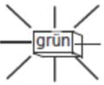
Technische Daten der Antriebe ohne Positionselektronik (Auf/Zu Antriebe)
Stellkraft                  4,5 kN, 18 kN, 20 kN,25 kN
Betriebsart (nach IEC-34)   S2 30min
                            S4 - 1200 c/h 50%ED
Netzanschlüsse              24 V AC Einphasen-Wechselstrom
                            110/120V AC Einphasen-Wechselstrom
                            230 V AC Einphasen-Wechselstrom
zul. Umgebungstemperatur    -20°C bis +80°C (S2) / -20°C bis +60°C (S4)
Einbaulage                  beliebig, jedoch Motor nicht nach unten
Schutzart (EN 60529)        IP 65
max. Leistungsaufnahme      4,5 KN: 19W, 18 kN: 52W, 20 kN: 145 W, 25 kN: 160W
Motorschutz                 Thermoschalter
Ventiladaption              Manuelle Inbetriebnahme mittels Endschalter

Weiter technische Daten entnehmen Sie bitte den Datenblättern.

                                                   -5–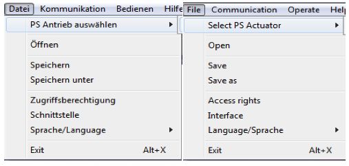
1.3       Einbau

Von der Armatur sind alle Verpackungsmaterialien zu entfernen.

Vor dem Einbau ist die Rohrleitung auf Verunreinigung und Fremdkörper zu untersuchen und
ggf. zu reinigen.

Das Stellventil ist entsprechend der Durchflussrichtung in die Rohrleitung einzubauen. Die
Durchflussrichtung ist am Gehäuse durch einen Pfeil angegeben. Das Segmentplattenventil
schließt und regelt das Medium in beide Durchflussrichtungen, jedoch ist der Einbau in
Pfeilrichtung unbedingt empfohlen. Beim Durchfluss entgegen der Pfeilrichtung ergeben sich
höhere Stellkräfte, die jeweilig möglichen Differenzdrücke müssen dem Datenblatt entnommen
werden.

Als Flanschdichtungen sind Dichtungen nach DIN EN 1514-1 bzw. ANSI B16.21 in der
jeweiligen Nenndruckstufe zu verwenden.

Wir empfehlen Flanschdichtungen aus Reingraphit mit Edelstahleinlage.

Die Einbaulage des Ventils ist beliebig, mit Ausnahme der Stellung „Haube nach unten“
                                °

                                                      90
                               90

                                                        °

Die Funktion der kompletten eingebauten Armatur ist vor der Inbetriebnahme der Anlage zu
überprüfen.

                                            -6–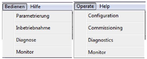
1.4       Explosionsschutz nach ATEX 2014/34/EU

         WARNUNG
         Die in diesem Kapitel aufgeführten Hinweise zum Betrieb der Armatur in
         explosionsgefährdeten Bereichen sind zwingend zu beachten!

Das Ventil Typ 5030 wurde nach der ATEX-Richtlinie einer Zündgefahrenbewertung für
nichtelektrische Geräte unterzogen. Daraus ergibt sich die folgende Kennzeichnung für Ventile
in den Nennweiten DN25 – DN100:

                           II 2G Ex h IIC T6…T2 X Gb

                           II 2D Ex h IIIC 85°C…220°C X Db

Ventile in den Nennweiten DN125 – DN800 sind wie folgt gekennzeichnet:

                           II 2/-G Ex h IIC T6…T2 X Gb

                           II 2/-D Ex h IIIC 85°C…220°C X Db

Alle Ventile in den Nennweiten DN125 – DN800 sind somit nur in ihrem Inneren, jedoch nicht im
Außenbereich für ATEX-Zonen geeignet.

Aus dieser Kennzeichnung ergeben sich Unterschiede in den einzelnen Varianten, die für einen
sicheren Betrieb in einer explosionsgefährdeten Atmosphäre zu beachten sind.
Grenzen des Betriebsbereichs
   • Die zu erwartende Oberflächentemperatur des Ventils ist von der Medientemperatur
       abhängig und kann maximal die Medientemperatur erreichen.
   • Die maximal erlaubte Medientemperatur ist von der der Ventilausführung abhängig und
       ist dem Datenblatt zu entnehmen.
   • Bei Schaltfrequenzen von mehr als 0,5 Hz ist eine zusätzliche Erwärmung des Antriebs
       um 10K über die Medientemperatur zu berücksichtigen. Schaltfrequenzen von über 2 Hz
       sind in explosionsgefährdeten Bereichen nicht zulässig.
Die Zuordnung der Temperaturklassen zur maximalen Oberflächentemperatur erfolgt nach DIN
EN ISO 80079-36 6,2,5 Tabelle 2:

  Temperaturklasse            Maximale Oberflächentemperatur
        T1                               ≤ 450°C
        T2                               ≤ 300°C
        T3                               ≤ 200°C
        T4                               ≤ 135°C
        T5                               ≤ 100°C
        T6                                ≤ 85°C

Die Kennzeichnung gilt für alle Ventile der aufgeführten Baureihe inklusive Antrieb jedoch nur in
den Standard-Ausführungen, die in den Datenblättern aufgeführt sind. Sonderausführungen und
andere Antriebe müssen einer eigenen Konformitätsbewertung nach ATEX unterzogen werden.

                                              -7–
Alle elektrischen und mechanischen Zubehörteile (z.B. Stellungsregler,
Grenzsignalgeber, Magnetventile usw.) müssen einer eigenen Konformitätsbewertung
nach ATEX unterzogen werden.
Im Zweifel wird angeraten, den Hersteller zu kontaktieren.
1.5 Öffnen der Antriebshaube
1. Gewindestift (A) lösen.
2. Knauf für die Handbetätigung (B)
abmontieren.
B 3. Haube mit beiden Händen nach oben
schieben und abnehmen.
A (Gegebenenfalls kann die Haube mit
einem Schraubendreher am Schlitz (D)
E
gelockert werden.)
C Montage der Haube:
1. Überprüfen, ob der Dichtring am Umfang
des Gehäuses richtig in der dafür
vorgesehenen Nut liegt.
2. Zur einfacheren Haubenmontage darf
der Dichtring leicht eingefettet werden.
D 3. Haube über die Handradwelle (E)
schieben.
4. Markierung am Haubenrand mit Nut im
Getriebegehäuse in Deckung bringen.
5. Haube bis über den O-Ring schieben.
ACHTUNG: Haube nicht
gewaltsam nach unten drücken.
Bei ordnungsgemäßem Sitz lässt sich
die Haube nicht mehr drehen und die
Haubenunterkante schließt mit der
Gehäusekante bündig ab.
6. Knauf für Handbetätigung so montieren,
dass er auf der Haubenoberseite
anliegt.
7. Knauf mit Gewindestift sichern.
(Der Gewindestift muss sich an der
abgeflachten Seite der Handradwelle
befinden.)
-8–1.6 Elektrischer Anschluss
Der elektrische Anschluss darf nur durch qualifiziertes Personal erfolgen.
Beachten Sie unbedingt bei Montage, Inbetriebnahme und Betrieb der
Geräte die entsprechenden nationalen Sicherheitsvorschriften (z. B. VDE
0100).
Alle Arbeiten dürfen nur im spannungslosen Zustand erfolgen.
Bei Nichtbeachten der entsprechenden Vorschriften können schwere
Körperverletzungen und/oder Sachschäden auftreten.
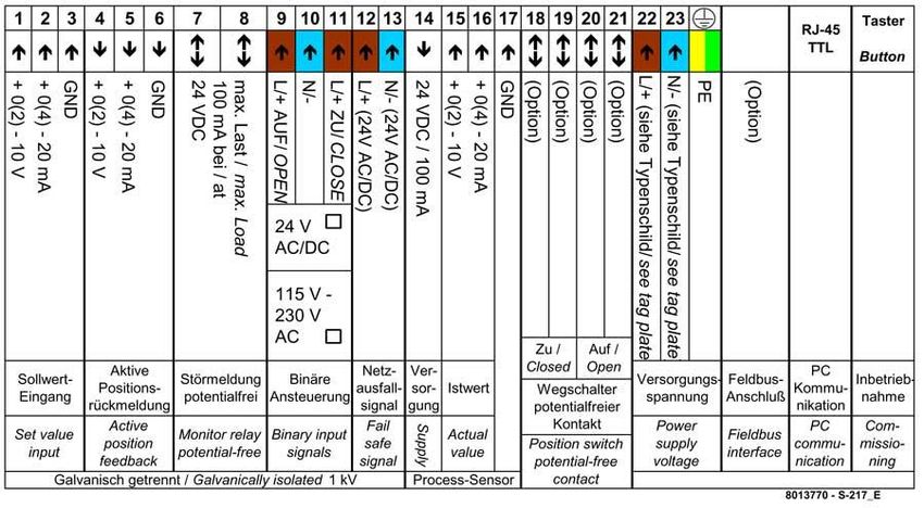
1.6.1 Anschlussbelegung für Antriebe mit Positionselektronik
Die Belegung der Anschlüsse und die Schaltfunktionen sind auf einem Schaltplan im
Klemmkasten des Antriebs angegeben. Die Anschlussklemmen sowie die Erdungsklemme
sind entsprechend gekennzeichnet.
-9–1.6.2 Anschlussbelegung für Antriebe ohne Positionselektronik (Auf/Zu)
Die Belegung der Anschlüsse und die Schaltfunktionen sind auf einem Schaltplan in der
Haube des Antriebs angegeben. Die Anschlussklemmen sowie die Erdungsklemme sind
entsprechend gekennzeichnet.
Der elektrische Anschluss des Antriebs erfolgt auf der Klemmplatine im Motorraum.
Klemmenbelegung:
X1 – X3 = Interne Verdrahtung
X4 = Potentiometer (optional)
X5/1 = Nullleiter
X5/2 = Motorphase (Öffnen)
X5/4 = Motorphase (Schließen)
X6 = zusätzliche Endschalter
X8 = Heizwiderstand (optional)
PE = Schutzleiter Anschluss am Gehäuse
Anschlussplan:
Schaltplan für Motor Ventile Typ 5030 ohne Positionselektronik (wiring diagram motor
valves type 5030 without position electronic / Schéma de câblage pour moteur de la type 5030
vanne Type 5030)
4,5 kN, 18kN, 20kN und 25kN AC
Endschalter Endschalter
(Ventil schließt) (Ventil öffnet)
limit switches limit switches
(Valve closes) (Valve opens)
Fin de course Fin de course
(Vanne fermée) (Vanne ouverte)
N = Nulleiter
X1/13
WE WE POT HZ L1 = Phase
M S3 S4 R1 WE = wegabhängiger Endschalter
J> 1~ POT = Potentiometer
X1/12 HZ = Heizwiderstand
C
N = neutral wire
S1 S2 L1 = phase
R WE = stroke dependent limit switch
POT = potentiometer
HZ = heating resistor element
PE 1 2 4 X5 1 2 3 4 5 6 X6 14 15 16 X4 1 2 X8 N = Neutre
L1 = Phase
1=N optionales Zubehör WE = stroke dependent limit switch
2 = L1 - AUF (open / ouverte) POT = potentiometer
(opt. accessories) HZ = heating resistor element
4 = L1 - ZU (close / fermée)
(Accessoires en option)
revised: designed:
21.07.2016 03.05.2016 Schlecht S 5030 0005 01
- 10 –Anschlussplan Industriestecker:
- 11 –1.7 Adaption des Antriebs
Alle Antriebe sind werkseitig auf die dazugehörige Armatur eingestellt und
geprüft.
Eine Adaption oder Justage ist nicht erforderlich.
Nach Reparatur oder bei Austausch des Antriebs muss jedoch die
Einstellung des Antriebs überprüft und ggf. eine neue Adaption
vorgenommen werden.
1.7.1 Antrieb ohne Positionselektronik (AUF/ZU)
Einstellen der Endschalter
1. Ventil von Hand in die geöffnete Position
fahren (unterste Ventilstellung)
2. Feststellschraube der Schaltnocke (2)
lockern.
3. Schaltnocke in Richtung des Endschalters
nach oben verschieben, bis dieser hörbar
klickt.
4. Feststellschraube anziehen.
5. Ventil von Hand in die geschlossene Position
fahren. (oberste Ventilstellung)
6. Feststellschraube der Schaltnocke (1)
lockern.
7. Schaltnocke in Richtung des Endschalters
nach unten verschieben, bis dieser hörbar
klickt.
8. Feststellschraube anziehen
9. Schaltpunkte der Endschalter überprüfen und
wenn nötig nachjustieren
- 12 –1.7.2 Antrieb mit Positionselektronik (Regelantriebe)
Verbinden Sie den Antrieb mit Ihrem PSCS-
USB Kabel mit dem PC und starten Sie die
1 Software PSCS.
Wählen Sie den Antriebstyp und die
2 Schnittstelle in der Software aus.
Wählen Sie Bedienen Inbetriebnahme
aus und bestätigen den Dialog mit OK.
3
Bei der manuellen Inbetriebnahme muss der
korrekte Sollwert für die Zu-Position bzw.
das binäre Stellsignal für das Zu-Fahren
4 dauerhaft angelegt sein.
Mit dem Balken ZU-Position einstellen und
mit „senden“ überprüfen.
5 Speichern mit OK.
Grüne LED leuchtet Antrieb erfolgreich
in Betrieb genommen und bereit
6
Anmerkung: Bei Regelantrieben ist kein automatischer Abgleich möglich. Die PSCS Software
ist dazu erforderlich.
- 13 –1.8 Störmeldeausgang
(Nur bei Antrieben mit Positionselektronik)
Während des Betriebes werden permanent alle Parameter und Betriebszustände des
Antriebs überwacht. Zur Meldung von Störungen kann an den Potentialfreien Klemmen 7 und
8 mit einer maximalen Belastung von 24 V DC / 100 mA eine Meldung an die Prozess-
Leitstelle erfolgen.
Die als Sammelstörmeldung ausgegebenen Meldungen können mittels der
Parametrierungssoftware konfiguriert werden.
Im Klemmkasten befinden sich je eine rote
und eine grüne Leuchtdiode zur Anzeige
von Betriebs- und Störzuständen.
Bedeutung der LED-Anzeigen
Rote LED Grüne LED
leuchtet dauerhaft
leuchtet dauerhaft
blinkt langsam
blinkt langsam
blinkt schnell
blinkt schnell
aus
aus
Betriebszustände
X X Normaler betriebszustand
X X Antrieb im Abgleichbetrieb
X X Antrieb nicht abgeglichen
Fehler im Umfeld des Antriebs
X X Drehmomentfehler: Innerhalb des Verfahrweges wurde ein zu großes Drehmoment gemessen.
X X Sollwertfehler: Sollwert ist nicht angelegt oder nicht im parametrierten Bereich.
X X Beim Abgleich gespeicherte Endlage wurde nicht erreicht.
X X Beim Abgleich gespeicherte Endlage wurde überfahren.
X X Versorgungsspannung im Antrieb ist zu gering.
Fehler im Antrieb
X X Elektronik-Fehler / Parameterdaten ungültig.
X X Überhitzung: kritische oder maximale Temperatur wurde erreicht.
X X Mechanischer Fehler im Antrieb
- 14 –1.9 Kommunikationssoftware
(Optional nur bei Antrieben mit Positionselektronik)
Zur Kommunikation und Parametrierung mit einem PC wird
der Antrieb an der RJ45-Buchse über das
Kommunikationskabel mit seriellen Schnittstelle (RS232)
des PC verbunden.
Eine genaue Beschreibung der Kommunikation finden Sie
in einer gesonderten Betriebsanleitung, die der Software
beigefügt ist.
Über die Software lassen sich unter anderem folgende Parameter konfigurieren.
Stellsignal: Strom oder Spannung sowie Signalbereich
Rückmeldung: Strom oder Spannung sowie Signalbereich
Sollwert Mittelung: zur Glättung des Sollwertsignals
Stellgeschwindigkeit: 50% bis 100%
Schließrichtung: einfahrend oder ausfahrend
Max. Antriebskraft
Fehlermeldungen: Hier kann festgelegt werden, welche Fehler über den
Strommeldeausgang gemeldet werden sollen und wie der Antrieb bei
Auftreten bestimmter Fehler reagieren soll.
Kennlinie: Hier kann über max. 16 Stützpunkte eine benutzerdefinierte
Kennlinie eingestellt werden.
Monitor: Mit der Monitorfunktion werden Werte wie Sollwert, Istwert,
Motorstrom, Motortemperatur, Motorspannung und Motorposition
laufend vom Antrieb ausgelesen und grafisch dargestellt.
Diagnosefunktionen: Mit der Diagnosefunktion können die Gesamtzahl der
Einschaltvorgange, die Gesamtbetriebszeit, die Laufzeit des Motors
und einige anderen Werte erfasst werden.
- 15 –1.10 Handbetätigung
Zur Betätigung des Antriebs bei
Spannungsausfall oder bei Einstellarbeiten
(Ventilaufbau) ist eine Handbetätigung an der
Oberseite des Antriebs vorhanden.
Bei Ventilen mit Netzausfallsicherung
(Akkupack) muss diese vorher elektrisch
abgeklemmt werden, um ein Verfahren von
Hand zu ermöglichen.
Durch Drehen der Handbetätigung im
Uhrzeigersinn öffnet das Ventil (bei den
Antrieben PSL 210 - PSL 214)
Durch Drehen der Handbetätigung gegen den
Uhrzeigersinn öffnet das Ventil (bei den
Antrieben PSL 320 / PSL 325)
Während des Betriebs sollte nicht an der Handbetätigung gedreht werden, da
der Antrieb je nach Betriebsart versucht, die Abweichung der Position aus zu
regeln.
- 16 –1.11 Demontage und Montage des Antriebes
Handrad 33
Säule 27
Kupplung 30
Spannschrauben 31
Kupplungsmutter 32
Kontermutter 34
Zahnstange 17
Flansch f. Säule 24
Mutter f. Säule 28
5030 0002 - D
Während des Betriebs sollte nicht an der Handbetätigung gedreht werden, da
der Antrieb je nach Betriebsart versucht, die Abweichung der Position aus zu
regeln.
- 17 –1.11.1 Demontage des Antriebes.
1. Achten Sie vor Beginn auf die Funktion der „Handbetätigung“ (1.9)!
2. Spannschrauben (31) lösen.
3. Kontermutter (34) lösen.
4. Kupplungsmutter (32) ist nun lose, durch drehen kann Zahnstange (17)
herausgeschraubt werden.
5. Mutter f. Säulen (28) abschrauben.
6. Antrieb abnehmen.
1.11.2 Montage des Antriebes.
1. Sicherstellen das sich die Kupplungsmutter (32) von Hand drehen lässt.
2. Elektrischen Antrieb inklusive montierter Säulen (27) auf den Flansch für Säule (24)
aufstecken.
3. Durch Drehen des Handrads (33) Antrieb ausfahren bis die Kupplungsmutter (32) auf die
Zahnstange (17) geschraubt werden kann (Kontermutter (34) muss bereits mit der
Zahnstange (17) verschraubt sein).
4. Kupplungsmutter etwa (17) 12mm (bei DN25-DN150), bzw. 16mm (bei DN200-DN300)
in die Zahnstange (17) einschrauben.
5. Kontermutter (34) anziehen.
6. Spannschrauben (31) über Kreuz mit 8Nm anziehen.
7. Mutter f. Säulen (28) anziehen.
8. Wenn die Funktionseinheit im offenen Zustand ist (Ventil an unterster Stellung, Durchfluss
geöffnet) und die Zahnstange (17) den Sicherheitsabstand von 1mm bzw. 2mm einhält,
kann der Lochflansch (20) mit eingelegtem Kupferring (19) montiert werden.
Bevor der Antrieb elektrisch angeschlossen wird sicherstellen das die
wegabhängigen Endschalter eingestellt worden sind (siehe 1.7.1 bzw. 1.7.2). Bei
Nichtbeachten kann das Ventil beschädigt werden!
1.12 Demontage und Montage der Funktionseinheit /
Ventilunterteil
1.12.1 Demontage der Funktionseinheit / Ventilunterteil
1. Vor Beginn der Demontage muss das Ventil (und somit auch der der Antrieb) in unterer
Stellung (Durchfluss geöffnet) sein. Hinweis: Der Antrieb muss demontiert sein.
2. Schleissring (16) abnehmen.
3. Lochflansch (20) inkl. Kupferring (19) demontieren.
4. Sicherungsring (15) mit Sicherungsringzange ausbauen. Achtung: unter dem
Federhalter (12) befinden sich Druckfedern die unter Spannung stehen. Bei dem
Entfernen des Sicherungsrings entspannen sich diese Federn.
5. Losscheibe (4) (inkl. Gleitring (10) und Federhalter (12)) aus dem Gehäuse entnehmen.
6. Stellschraube (26) lösen. Flansch f. Säule (24) demontieren.
7. Zahnstange (17) nach oben hin entnehmen.
8. Packung (23) und Anpressringe (22) entnehmen.
- 18 –9. Festscheibe (3) inkl. Zylinderstift (6) demontieren. Anschließend Labyrinthring (8)
entfernen (Labyrinthring entfällt bei der ungekapselten Version). Bei korrosiven Medien
kann sich das demontieren schwergängig gestalten.
10. Federhalter (12) abziehen (bei gekapselter Version).
11. Von der Losscheibe den O-Ring (14) abnehmen (nur bei gekapselter Version). Gleitring
(10) abziehen.
12. Druckfedern (11) aus dem Federhalter entnehmen (bei korrosiven Medien kann sich
das demontieren schwergängig gestalten).
1.12.2 Montage der Funktionseinheit / Ventilunterteil
1. Zur Montage der Funktionseinheit muss der O-Ring (7) im Gehäuse eingelegt sein. Es
muss vor Montage geprüft werden ob der O-Ring (7) vollständig in der dafür
vorgesehenen Gehäusenut eingelegt ist. Bei gekapselter Version muss vor Montage
zusätzlich geprüft werden, ob die O-Ringe (13 und 14) ebenfalls vollständig in die Nuten
eingelegt sind.
2. Zylinderstifte (2) bei der Bohrung in der Festscheibe (3) einlegen. Dieser Zylinderstift ist
nur bis einschließlich DN80 vorhanden. Ab DN100 ist dieser Stift fest mit dem Gehäuse
verschweißt.
3. Festscheibe (3) in das Gehäuse einpressen (vorzugsweise mit einer kleiner hydraulischen
Presse). Achtung: Auf richtige Lage des Zylinderstiftes (2) achten!
4. Labyrinthring ((8) nur bei gekapselter Version) und Zylinderstift (6) in die vorgesehene Nut
bzw. Bohrung der Festscheibe (3) setzen.
5. Laufbuchse (18) in das Gehäuse einlegen.
6. Zahnstange (17) in das Gehäuse (1) einführen. Der vorgeschriebene Sicherheitsabstand
zwischen Zahnstange (17) und Lochflansch (20) beträgt bei DN25-DN32: 1mm, bei DN40-
DN300: 2mm!
7. Anpressringe (22) und Packung (23) in richtiger Reihenfolge einlegen.
8. Flansch für Säule (24) mit Zylinderschrauben (25) auf das Gehäuse (1) anschrauben.
9. Stellschraube (26) in den Flansch (24) schrauben. Bei erstmaliger Montage „handfest“
anziehen, nach etwas Einsatzzeit muss die Stellschraube nachgezogen werden, bis keine
Leckage mehr feststellbar ist. Die Stopfbuchspackung dabei nicht zu stark anziehen da
dies zu erhöhten Verschleiß und Reibung führt. Eine regelmäßige Sichtprüfung auf äußere
Leckage wird empfohlen, die Intervalle sind aufgrund des hohen Einflusses von dem
Medium vom Anwender selbst festzulegen. Sollte eine Leckage festgestellt werden muss
die Stellschraube (26) leicht nachgezogen werden, anschließend ist eine erneute Kontrolle
notwendig.
10. Kontermutter (34) auf das Gewinde der Zahnstange (17) schrauben.
11. Losscheibe (4) einlegen. Position der Schlitze: offen. (Ventil geöffnet an unterster Position)
12. Zylinderstifte (9) mit Federhalter (12) montieren und zur Seite legen.
13. Die Druckfedern (11) in die Bohrungen des Federhalters einlegen. Den Gleitring (10) nun
auf den Federhalter setzen (Bohrungen für die Passstifte (9) müssen fluchten).
14. Vormontierte Einheit (Gleitring (10) voraus) auf die Losscheibe setzen.
15. Eingebaute Einheit nach unten drücken und Sicherungsring (15) montieren. Achtung:
Sicherungsring muss vollständig in der dafür vorgesehenen Nut im Gehäuse positioniert
sein!
16. Schleißring (16) einsetzen.
- 19 –1.12.3 Schmier- und Klebeplan
Der Schmier- und Klebeplan gilt für alle Standardausführungen dieses
Ventiltyps.
Informieren Sie sich beim Hersteller über die geeigneten Schmierstoffe.
Bei Sonderausführungen (z. B. silikonfrei, für Sauerstoffanwendungen oder
für Lebensmittelanwendungen) sind gegebenenfalls andere Fettsorten zu
verwenden.
geklebt
geklebt
gefettet
gefettet
gefettet
geklebt
1.13 Entsorgung
Das Gerät und die Verpackung müssen entsprechend den einschlägigen Gesetzen und
Vorschriften im jeweiligen Land entsorgt werden
- 20 –2 Operating Instructions (Englisch)
2.1 SPV1 Series spare parts list
(Only use original spare parts from Schubert & Salzer Control Systems!)
el.actuator
lock nut 34
column 27
set screw 26
cyl. screw 25
washer for column 24
nut for column 28
compression ring 22
packing 23
compression ring 22
sliding ring 10
gear rack 17 circlip 15
body 1 spring retainer 12
cyl.pin 2 compression spring 11
o-ring
cyl. pin 6
only at 14
encapsulated version
gear segment 5
from DN80
control disc 4
fixed disc 3 wear ring 16
Labyrinthring 8 cyl.pin 9
only at
encapsulated version o-ring
o-ring 7
only at 13
encapsulated version
liner 18
copper ring 19
hole flange 20
hexagon screw 5030 0001 - E
for hole flange 21
In addition to the individual spare parts, repair kits which contain all seal and wear parts are
also available for all SPV1 products. The segment disc valve is maintenance-free.
- 21 –2.2 Technical data
Valve technical data
Design Wafer type design
for flanges according to DIN EN 1092-1, Form B
Nominal sizes DN25 to DN300
Nominal pressure DN25 to DN150 PN 25 nach DIN 2401
(suitable for PN 10 to PN 25 flanges)
DN 200 PN 25 according to DIN 2401
DN 250 to DN 300 PN 16 according to DIN 2401
Fluid temperature -60°C to +220°C
Setting ratio 60:1
Characteristic curve modifiziert linear
Leakage rate % ofTechnical data of the actuators without position electronics (on/off)
Driving force 4,5 kN, 18 kN, 20 kN,25 kN
Type of duty S2 30min
(according IEC-34) S4 - 1200 c/h 50%ED
Power connections 24 V AC
110/120V AC
230 V AC
Ambient temperature -20°C up to +80°C (S2) / -20°C up to +60°C (S4)
Mounting position free of choice, but motor not top down
Protecting class (EN 60529) IP 65
max. power consumption 4,5 KN: 19W, 18 kN: 52W, 20 kN: 145 W, 25 kN: 160W
Engine protection thermal swicht
Valve adaption manual initial operation with limit switches
Further technical data can be found in the data sheets.
2.3 Installation
Remove all packing materials from the valve.
Prior to the installation the pipeline should be checked for contamination and foreign particles
and cleaned if necessary.
The control valve has to be mounted to the pipeline according to the direction of flow, which is
indicated by an arrow on the valve body. The segment disc valve closes and regulates the fluid
in both directions of flow. However, installation in the direction indicated by the arrow is strongly
recommended. In case of a fluid flow in opposite direction of the arrow, please consult the
differential pressure table in the data sheet, as kind of operation leads to significantly higher
actuating forces, thus reducing the possible differential pressure.
Use flange seals acc. to DIN EN 1514-1 or ANSI B16.21 in the respective nominal pressure.
We recommend flange seals made from pure graphite with a stainless steel backup.
The valve can be installed as desired with the exception of the "cover pointing downwards"
position.
°
90
90
°
The proper function of the completely mounted valve has to be checked prior to putting the
installation into service.
- 23 –2.4 Explosion protection according to ATEX 2014/34/EU
WARNING
The instructions for operating the valve in potentially explosive atmospheres,
as detailed in this chapter, must be observed without fail!
The valve type 5030 has been subjected to an ignition hazard assessment for non-electrical
devices in accordance with the ATEX directive. This results in the following marking for valves
in sizes DN25 – DN100 / 1” - 4”:
II 2G Ex h IIC T6…T2 X Gb
II 2D Ex h IIIC 85°C…220°C X Db
Valves in size DN125 – DN800 / 5” – 32” are marked like this:
II 2/-G Ex h IIC T6…T2 X Gb
II 2/-D Ex h IIIC 85°C…220°C X Db
All valves in sizes DN125 – DN800 / 5“ – 32“ are only suitable for ATEX areas on the inside, not
on the outside.
This marking indicates differences in the individual variants, which must be observed for safe
operation in a potentially explosive atmosphere.
Limitations of the operating range
• The expected surface temperature of the valve depends on the media temperature and
can reach the media temperature at the most.
• The maximum permitted media temperature depends on the valve version and can be
taken from the data sheet.
• In the case of switching frequencies of more than 0.5 Hz, an additional heating of the
actuator by 10K above the media temperature must be taken into account. Switching
frequencies higher than 2 Hz are not permitted in potentially explosive atmospheres.
The temperature classes are assigned to the maximum surface temperature in accordance with
EN ISO 80079-36 6,2,5 Table 2:
Temperature class Maximum surface temperature
T1 ≤ 450°C / 842°F
T2 ≤ 300°C / 572°F
T3 ≤ 200°C / 392°F
T4 ≤ 135°C / 275°F
T5 ≤ 100°C / 212°F
T6 ≤ 85°C / 185°F
The marking applies to all valves from the listed series including actuator, but only in the
standard versions, which are listed in the data sheets. Special versions and other actuators
must be subjected to a separate conformity assessment according to ATEX.
- 24 –All electrical and mechanical accessories (e.g. positioners, limit signal transmitters,
solenoid valves, etc.) must be subjected to their own conformity assessment according
to ATEX.
2.5 Opening the cover of the actuator
1. Unscrew threaded pin (A).
2. Disassemble the stud for manual
actuation (B).
B 3. Using both hands, push the stud
upwards and remove it. (Where
A necessary, the stud can be loosened
using a screwdriver on the slot (D).)
E
Assembling the cover:
C
1. Examine whether the sealing ring is
correctly positioned in the corresponding
groove along the circumference of the
housing.
2. The sealing ring can be slightly greased
in order to ensure a simpler assembly of
D the cover.
3. Push the cover over the hand wheel shaft
(E).
4. Align the marking on the edge of the
cover with the groove in the gear
housing.
Push the cover over the O-ring.
ATTENTION: Do not forcefully
push the cover downwards.
If seated correctly, the cover can no
longer be rotated and the lower edge of
the cover is flush with the edge of the
housing.
5. Assemble the stud for the manual
actuation in such a manner that it
touches the upper side of the cover.
6. Secure the stud with the threaded pin.
(The threaded pin must be located on the
levelled side of the hand wheel shaft.)
- 25 –2.6 Connection to Electricity Supply
The electrical connection must only be carried out by qualified personnel.
It is essential that the respective national safety regulations (e.g. VDE
0100) are observed during the assembly, commissioning and operation of
the devices.
All work has to be carried out isolated from the power supply.
Disregarding the relevant regulations may cause serious physical injuries
and/or property damage.
2.6.1 Wiring for actuators with position electronics
The wiring connection and the switching functions are stated in a circuit diagram located in the
terminal box of the actuator. The connection terminals as well as the ground terminals are
labelled accordingly.
- 26 –2.6.2 Wiring for actuators without position electronics (On/Off)
The wiring connections and the switching functions are stated in a plugging diagram located
in the cover of the actuator. The connection terminals as well as the ground terminals are
labelled accordingly.
The electrical connection of the actuator is performed on the terminal board in the engine
compartment.
Terminal assignment:
X1 – X3 = Internal cabling
X4 = Potentiometer (optional)
X5/1 = Neutral line
X5/2 = Engine phase (open)
X5/4 = Engine phase (close)
X6 = Additional limit switch
X8 = Heating resistor (optional)
PE = Connection protective conductor on the
housing
Connection diagram:
Schaltplan für Motor Ventile Typ 5030 ohne Positionselektronik (wiring diagram motor
valves type 5030 without position electronic / Schéma de câblage pour moteur de la type 5030
vanne Type 5030)
4,5 kN, 18kN, 20kN und 25kN AC
Endschalter Endschalter
(Ventil schließt) (Ventil öffnet)
limit switches limit switches
(Valve closes) (Valve opens)
Fin de course Fin de course
(Vanne fermée) (Vanne ouverte)
N = Nulleiter
X1/13
WE WE POT HZ L1 = Phase
M S3 S4 R1 WE = wegabhängiger Endschalter
J> 1~ POT = Potentiometer
X1/12 HZ = Heizwiderstand
C
N = neutral wire
S1 S2 L1 = phase
R WE = stroke dependent limit switch
POT = potentiometer
HZ = heating resistor element
PE 1 2 4 X5 1 2 3 4 5 6 X6 14 15 16 X4 1 2 X8 N = Neutre
L1 = Phase
1=N optionales Zubehör WE = stroke dependent limit switch
2 = L1 - AUF (open / ouverte) POT = potentiometer
(opt. accessories) HZ = heating resistor element
4 = L1 - ZU (close / fermée)
(Accessoires en option)
revised: designed:
21.07.2016 03.05.2016 Schlecht S 5030 0005 01
- 27 –Industrial plug connection diagram:
- 28 –2.7 Adaption of actuator
All actuators are factory-adjusted and tested for the respective valve.
No adaptation or adjustment is required.
However, following repair or in the event of a actuator replacement, the
setting of the actuator be examined and it may be necessary to perform
an adaption to the actuator.
2.7.1 Actuator without position electronics (on/off)
Adjusting the limit switches
1. Move the valve into the open position by hand
(lowermost valve setting)
2. Loosen the locking screw belonging to the
switch cam (2).
3. Push the switch cam upwards in the direction
of the limit switch until it audibly clicks into
place.
4. Tighten the limit screw.
5. Move the valve into the closed position by
hand. (uppermost valve position)
6. Loosen the locking screw belonging to the
switch cam (1).
7. Push the switch cam downwards in the
direction of the limit switch until it audibly clicks
into place.
8. Tighten the locking screw
9. Examine the switching points of the limit switch
and adjust where necessary
- 29 –2.7.2 Actuators with position electronics (control actuators)
Using your PSCS-USB cable, connect the
actuator to the PC and start the PSCS
1 software.
Select the actuator type and interface in the
2 software.
Select operation commissioning and
confirm the dialogue with OK.
3
When performing manual commissioning,
the correct target value for the closed
position or the binary control signal for the
4 close movement must be permanently set-
up.
Set the CLOSE position using the bar and
examine via "send".
5 Save by pressing OK.
Green LED lights up Actuator has been
successfully commissioned and is ready
6
Note: No automatic adaption is possible when dealing with control actuators. The PSCS
software is required for this.
- 30 –2.8 Error signal output
(actuators with position electronics only)
All actuator parameters and operating conditions are monitored during operation. In order to
report faults, a notification can be made to the process control centre on potential-free
terminals 7 and 8 with a maximum load of 24 V DC / 100 mA.
The notifications which are issued as a collective fault message can be configured via the
parameterisation software.
A red and a green LED are installed in the
terminal box in order to display operating
and error statuses.
Meaning of the LED displays
Red LED Green LED
flashes quickly
flashes quickly
flshes slowly
flshes slowly
permanently
permanently
lights
lights
off
off
State of Operation
X X Normal operation
X X Actuator in adjustment mode
X X Actuator not adjusted
Errors Related to Actuator Conditions
X X Torque error: Within the valve stroke a too high torque has been measured.
X X Set point error: Set point signal not connected or not in the parametrized range.
X X End position stored through adaptation procedure has not been reached.
X X End position stored through adaptation procedure has been over-travelled.
X X Actuator supply voltage too low.
Actuator Errors
X X Elektronic error / parameter data not valid.
X X Overheating: critical or maximum temperature achieved.
X X Mechanical actuator error
- 31 –2.9 Communication software
(optional with position electronics only)
In order to perform communication and parameterisation
with a PC, the actuator is connected to the RJ45 bush via
the communication cable with the serial interface (RS232)
of the PC.
An accurate description of the communication can be found
in the separate operating instructions which are enclosed
with the software.
Some of the parameters which can be configured via the software are listed below:
Set point signal: current or voltage as well as signal range
Response: current or voltage as well as signal range
Feedback: In order to smoothen the target value signal
Stroking time: 50% to 100%
Closing direction: Retracting or extending
Max. drive force
Error messages: The errors which should be reported via the current message output
and how the actuator should respond if certain faults occur are
determined here.
Characteristic curve: A user-defined characteristic curve can be set via a maximum of 16
control points.
Monitor: Values such as the set point, actual value, motor current, motor
temperature, motor voltage and motor position are constantly read
from the actuator and graphically illustrated with the monitor function.
Diagnosis functions: The total number of the switching-on processes, the overall operating
time, the running time of the motor as well as some other values can
be recorded with the diagnosis function.
- 32 –2.10 Manual actuation
A manual actuation is provided on the upper
side of the actuator in order to actuate in the
event of a power cut or when performing
setting work (valve assembly).
When dealing with valves which are equipped
with fail save protection (battery pack), this
protection has to be disconnected in advance
in order to enable a manual process.
The valve opens when the manual actuation
is rotated in a clockwise direction (on the PSL
210 - PSL 214 actuators)
The valve opens when the manual actuation
is rotated in an anti-clockwise direction (on
the PSL 320 - PSL 325 actuators)
The manual actuation should not be rotated during operation as the actuator,
depending on the type of operation, is attempting to regulate the position
deviation.
- 33 –2.11 Disassembly and assembly of the actuator
hand wheel 33
column 27
clutch 30
clamping screw 31
cuppling nut 32
lock nut 34
gear rack 17
flange f. column 24
nut f. columns 28
5030 0002 - E
The manual actuation should not be rotated during operation as the actuator,
depending on the type of operation, is attempting to regulate the position
deviation.
- 34 –2.11.1 Disassembly of the actuator
1. Take note of the "manual actuation function” (2.9) before starting.
2. Unscrew the clamping screws (31).
3. Unscrew the lock nut (34).
4. Now the coupling nut (32) is loose. The gear rack (17) can be unscrewed by rotating it.
5. Unscrew the nut for the columns (28).
6. Remove the actuator.
2.11.2 Assembly of the actuator
1. Ensure that the coupling nut (32) can be turned by hand.
2. Insert the electrical actuator incl. assembled columns (27) on to the flange for the column
(24).
3. By rotating the hand wheel (33), extend the actuator until the coupling nut (32) can be
screwed onto the gear rack (17) (the lock nut (34) must already be screwed to the gear
rack (17)).
4. Screw the coupling nut (17) into the gear rack (17) by approx 12 mm (for DN25-DN150)
or 16 mm (for DN200-DN300).
5. Tighten the lock nut (34).
6. Tighten the clamping screws (31) crosswise with 8 Nm of torque.
7. Tighten the nut for the columns (28).
8. The hole flange (20) complete with inserted copper ring (19) can be assembled if the
functional unit is open (valve at the lowest point, throughput open) and the gear rack (17)
observes the safety distance of 1 mm or 2 mm.
Ensure that the path-dependent limit switches have been set (see 2.7.1 or
2.7.2) before electrically connecting the actuator. The valve can become
damaged if this rule is not observed
2.12 Disassembly and assembly of function unit / lower part
2.12.1 Disassembly of the function unit / lower part
1. The valve (and therefore also the actuator) has to be in the lower position (flow open)
prior to disassembly. Note: The actuator has to be disassembled.
2. Remove the wear ring (16).
3. Disassemble the hole flange (20) incl. copper ring (19).
4. Disassemble the circlip (15) using circlip pliers. Attention: Pressure springs which are
under pressure are located beneath the spring holder (12). These springs are relieved
of pressure when the circlip is removed.
5. Remove the loose disc (4) (incl. slide ring (1) and spring holder (12)) from the housing.
6. Undo adjusting screw (26). Dismantle the flange for the column (24).
7. Remove the gear rack (17) upwards.
8. Remove the packing (23) and pressure rings (22).
9. Disassemble the fixed disc (3) incl. cylinder pin (6). Subsequently remove the labyrinth
ring (8) (the labyrinth ring is omitted from the non-encapsulated version). The
disassembly may be difficult when dealing with corrosive media.
10. Remove the spring holder (12) (when dealing with the encapsulated version).
- 35 –11. Remove the O-ring (14) from the moving disc (only when dealing with the encapsulated
version). Remove the sliding ring (10).
12. Remove the pressure springs (11) from the spring holder (the disassembly may be
difficult when dealing with corrosive media).
2.12.2 Assembly of the function unit / lower part
1. The O-ring (7) must be inserted in the housing in order to assemble the function unit.
Before installation, it must be examined whether the O-ring (7) is fully installed in the
intended housing groove. When dealing with an encapsulated version, an additional check
must take place prior to assembly that the O-rings (13 and 14) are also fully inserted in the
grooves.
2. In the bore hole, insert cylinder pins (2) into the fixed disc (3). This cylinder pin is only
available up to and including DN80. From DN100 and above, this pin is firmly welded to
the housing.
3. Push the fixed disc (3) into the housing (preferably with a small hydraulic press). Attention:
Pay attention to the correct position of the cylinder pin (2)!
4. Insert the labyrinth ring ((8) only when dealing with the encapsulated version) and the
cylinder pin (6) into the intended groove / bore hole of the fixed disc (3).
5. Insert the liner (18) into the housing.
6. Insert the gear rack (17) into the housing (1). The required safety distance between the
gear rack (17) and the hole flange (20) amounts to 1 mm for DN25-DN32 and 2 mm for
DN40-DN300.
7. Insert the pressure rings (22) and packing (23) in the correct sequence.
8. Using cylinder screws (25) screw the flange for the column (24) to the housing (1).
9. Screw the adjusting screw (26) into the flange (24). When assembling for the first time,
only tighten by hand. After a certain period of operation, the adjusting screw must be re-
tightened until no further leaks can be detected. Please do not overtighten the packing as
this could lead to increased wear and friction. We recommend to regularly carry out a
visual check in order to detect an external leakage. We are not able to propose
maintenance intervals as this is related to the fluid and the application. In case you detect
a leakage you can retighten the set screw (26) slightly and repeat the visual control.
10. Screw the lock nut (34) on to the thread of the gear rack (17).
11. Insert the moving disc (4). Position of the slots: Open (Valve open at the lowermost
position).
12. Assemble the cylinder pins (9) with spring holder (12) and place to side.
13. Insert the pressure springs (11) into the bore holes of the spring holder. Now apply the
sliding ring (10) to the spring holder (the bore holes for the cylinder pins (9) must align).
14. Apply the pre-assembled units (sliding ring (10) pointing forwards) on the loose disc.
15. Push the installed unit downwards and assemble the circlip (15). Attention: Circlip must be
fully positioned in the intended groove in the housing!
16. Insert the wear ring (16).
- 36 –2.13 Lubrication and bonding plan
The lubrication and bonding plan applies for all standard designs of this
valve type.
Please obtain further information regarding suitable lubricants from the
manufacturer.
Other grease types may be used when dealing with special designs (e.g.
silicone-free for oxygen applications or foodstuff applications).
bonded
bonded
lubricated
with grease
lubricated
with grease
lubricated
with grease
bonded
5030 0001- Schmier-BA-E
- 37 –3 Manuel d‘utilisation (français)
3.1 Liste des pièces de rechange Série SPV1
(N’utiliser que des pièces de rechange d’origine Schubert & Salzer Control Systems!)
Actionneur électrique
Contre-écrou 34
colonne 27
Vis de réglage 26
vis cyl. 25
rondelle de colonne 24
écou de colonne 28
bague de pression 22
presse étoupe 23
bague de pression 22
anneau de glissement
roue dentée 17 serre clip 15
corps 1 support de ressort 12
goupille cyl. 2 ressort de pression 11
joint torrique 14
seulement avec une
goupille cyl. 6 version encapsulée
segment denté 5
a partir de DN80
disque rotatif 4
disque fixe 3 bague d'usure 16
bague á labyrinthe 8 goupille cyl. 9
seulement avec une
version encapsulée joint torrique 13
seulement avec une
joint torique 7 version encapsulée
coussinet 18
anneau en cuivre 19
Bride percée 20
Boulon hexagonal
pur bride 21
- 38 –En plus des différentes pièces de rechange des kits de réparation, comprenant des joints et
des pièces d’usure, sont disponibles pour toutes les vannes SPV1. La vanne segment à
disque est considérée comme exempte d’entretien.
3.2 Informations techniques
Informations techniques de la vanne
Entre-brides
Exécution
Pour bride selon DIN EN 1092-1 Type B
Diamètre nominal DN25 à DN300
Pression nominale DN25 à DN150 PN 25 selon DIN 2401
(adaptée pour bride PN 10 à PN 25)
DN 200 PN 25 selon DIN 2401
DN 250 à DN 300 PN 16 selon DIN 2401
Température fluide -60°C à +220°C
Rapport de réglage 60:1
Courbe caractéreistique Linéaire modifiée
Classe de fuite % deInformations techniques de l’actionneur sans positionneur électronique
(Ouvert/Fermé)
Force de réglage 4,5 kN, 18 kN, 20 kN,25 kN
Prescriptions (selon IEC-34) S2 30min
S4 - 1200 c/h 50%ED
Raccordement réseau 24 V AC Monophasé - Courant alternatif
110/120V AC Monophasé - Courant alternatif
230 V AC Monophasé - Courant alternatif
Température ambiante
-20°C à +80°C (S2) / -20°C à +60°C (S4)
admissible
Position de montage Quelconque, toutefois pas le moteur vers le bas
Indice de protection (EN 60529) IP 65
Puissance absorbée maximale 4,5 KN: 19W, 18 kN: 52W, 20 kN: 145 W, 25 kN: 160W
Protection moteur Relais thermique
Mise en service manuelle au moyen d'interrupteurs de fin de
Adaptation vanne
course
Pour des informations techniques supplémentaires voir les feuilles techniques.
- 40 –3.3 Installation
Tous les matériaux d’emballage doivent être retirés de la vanne.
Avant l’installation la conduite doit être soumise à un contrôle sur la présence éventuelle
d‘impuretés et de corps étrangers et doit par la suite être nettoyée.
La vanne de régulation doit être montée dans la conduite en tenant compte du sens
d’écoulement du fluide. Le sens d’écoulement est indiqué sur le corps de la vanne au moyen
d’une flèche. La vanne segment à disque arrête et régule le fluide dans les deux sens
d’écoulement, toutefois il est fortement recommandé de monter la vanne dans le sens
indiqué par la flèche. Dans le cas d’un montage contraire au sens de la flèche une force de
manoeuvre plus importante en résulte, et par conséquent la valeur de la différence de
pression admissible telle qu’indiquée dans le tableau doit être réduite.
Les joints pour assemblage à brides à utiliser sont conformes respectivement à DIN EN
1514-1 et ANSI B16.21 selon le niveau de pression nominale.
Nous recommandons l’utilisation de joints de bride en graphite pur avec insert en acier
inoxydable.
La position de montage est au choix à l’exception de la position «capot vers le bas»
°
90
90
°
Avant la mise en service de l’installation les différentes fonctionnalités de la vanne doivent
être vérifiées.
- 41 –3.4 Protection antidéflagrante selon ATEX 2014/34/UE
AVERTISSEMENT
Les instructions données dans ce chapitre pour le fonctionnement de la vanne
dans des atmosphères potentiellement explosives doivent être respectées!
La vanne de type 5030 a été soumise à une évaluation des risques d'inflammation pour les
équipements non électriques conformément à la directive ATEX. Il en résulte l'identification
suivante pour vannes en diamètre nominal 25 jusqu’à 100
II 2G Ex h IIC T6…T2 X Gb
II 2D Ex h IIIC 85°C…20°C X Db
Pour vannes en diamètre nominale 125 jusqu’à 800, l’identification est
II 2/-G Ex h IIC T6…T2 X Gb
II 2/-D Ex h IIIC 85°C…20°C X Db
Tous les vannes en diamètre nominale 125 jusqu’à 800 sont seulement qualifiés pour zones
ATEX à l’intérieur mais pas à l’extérieur.
Ce marquage entraîne des différences dans les différentes variantes qui doivent être
respectées pour un fonctionnement sûr dans une atmosphère potentiellement explosive.
Limites de la plage de fonctionnement
• La température de surface prévue de la vanne dépend de la température du fluide et
peut atteindre au maximum la température du fluide.
• La température maximale admissible du fluide dépend de la version de la vanne et peut
être trouvée dans la fiche technique.
• Pour les fréquences de commutation supérieures à 0,5 Hz, il faut tenir compte d'un
réchauffement supplémentaire de l'actionneur de 10K au-dessus de la température du
milieu. Les fréquences de commutation supérieures à 2 Hz ne sont pas autorisées dans
les atmosphères potentiellement explosives.
L'attribution des classes de température à la température maximale de surface est effectuée
selon la norme DIN EN ISO 80079-36 6.2.5 Tableau 2:
Classe de temperature Température maximale de surface
T1 ≤ 450°C
T2 ≤ 300°C
T3 ≤ 200°C
T4 ≤ 135°C
T5 ≤ 100°C
T6 ≤ 85°C
Le marquage s'applique à toutes les vannes des séries énumérées, y compris l'actionneur, mais
uniquement dans les versions standard énumérées dans les fiches techniques. Les versions
- 42 –spéciales et autres actionneurs doivent être soumis à une évaluation de conformité distincte
selon ATEX.
Tous les accessoires électriques et mécaniques (par exemple, les positionneurs, les
interrupteurs de fin de course, les électrovannes, etc.) doivent être soumis à leur
évaluation de conformité spécifique selon ATEX
En cas de doute, il est conseillé de contacter le fabricant.
3.5 Ouverture du capot de l‘actionneur
1. Desserrer la goupille filetée (A).
2. Démonter le pommeau de la commande
manuelle (B).
B 3. Glisser avec les deux mains le capot vers
le haut et le retirer (Si nécessaire le capot
A peut être dégagé à la fente (D) au moyen
d’un tournevis).
E
Montage du capot:
C
1. Contrôler si la bague d’étanchéité est
correctement placée dans la rainure
prévue à cet effet à la circonférence du
corps.
2. Afin de faciliter le montage du capot la
bague d’étanchéité doit être légèrement
D graissée.
3. Glisser le capot par au-dessus de
l’arbre du pommeau (E).
4. Ajuster le marquage au bord du capot
avec la rainure du boîtier de
l’actionneur.
5. Glisser le capot jusqu’au-dessus du joint
torique.
ATTENTION: Ne pas pousser
brutalement le capot vers le bas.
Lors d’une pose correcte, le capot ne peut
plus tourner et le bord inférieur du capot
s’ajuste correctement au corps.
6. Monter le pommeau de la commande
manuelle de telle façon que celui-ci s’ajuste
avec la partie supérieure du capot.
7. Assurer le pommeau avec une goupille
filetée. (La goupille filetée doit se trouver
côté plat de l’arbre de commande)
- 43 –3.6 Raccordement électrique
Le raccordement électrique doit être exécuté uniquement par du
personnel qualifié.
Respecter impérativement les prescriptions nationales de sécurité (p.ex
VDE0100) lors du montage, la mise en service et le fonctionnement du
matériel.
Tous les travaux doivent être exécutés hors tension.
Le non respect des prescriptions réglementaires peuvent provoquer de
graves lésions corporelles et/ou des dommages au matériel.
3.6.1 Affectation des bornes pour actionneur à positionneur électronique
L’affectation des bornes et les fonctions de commutation sont reprises sur un plan placé dans
l’armoire à bornes. Les borniers de connexion ainsi que les bornes de mise à la terre sont
clairement indiqués.
- 44 –3.6.2 Affectation des bornes pour actionneur sans positionneur
électronique (Ouvert/Fermé)
L’affectation des bornes et les fonctions de commutation sont reprises sur un plan placé dans
le capot de l’actionneur.
Les borniers de connexion ainsi que les bornes de mise à la terre sont clairement indiqués.
Le raccordement électrique de l’actionneur se fait sur la platine à bornes située dans le
compartiment moteur.
Affectation des bornes:
X1 – X3 = Câblage interne
X4 = Potentiomètre (en option)
X5/1 = Neutre
X5/2 = Phase moteur (Ouvrir)
X5/4 = Phase moteur (fermer)
X6 = fin de course supplémentaire
X8 = Résistance de chauffage (en option)
PE = Connexion conducteur de protection au
corps
Plan de connexion:
Schaltplan für Motor Ventile Typ 5030 ohne Positionselektronik (wiring diagram motor
valves type 5030 without position electronic / Schéma de câblage pour moteur de la type 5030
vanne Type 5030)
4,5 kN, 18kN, 20kN und 25kN AC
Endschalter Endschalter
(Ventil schließt) (Ventil öffnet)
limit switches limit switches
(Valve closes) (Valve opens)
Fin de course Fin de course
(Vanne fermée) (Vanne ouverte)
N = Nulleiter
X1/13
WE WE POT HZ L1 = Phase
M S3 S4 R1 WE = wegabhängiger Endschalter
J> 1~ POT = Potentiometer
X1/12 HZ = Heizwiderstand
C
N = neutral wire
S1 S2 L1 = phase
R WE = stroke dependent limit switch
POT = potentiometer
HZ = heating resistor element
PE 1 2 4 X5 1 2 3 4 5 6 X6 14 15 16 X4 1 2 X8 N = Neutre
L1 = Phase
1=N optionales Zubehör WE = stroke dependent limit switch
2 = L1 - AUF (open / ouverte) POT = potentiometer
(opt. accessories) HZ = heating resistor element
4 = L1 - ZU (close / fermée)
(Accessoires en option)
revised: designed:
21.07.2016 03.05.2016 Schlecht S 5030 0005 01
- 45 –Sie können auch lesen