MERLIN-50 BEDIENUNGSANLEITUNG - OPERATING MANUAL MANUAL DE INSTRUCCIONES MODE D'EMPLOI - Liemke Thermal Optics
←
→
Transkription von Seiteninhalten
Wenn Ihr Browser die Seite nicht korrekt rendert, bitte, lesen Sie den Inhalt der Seite unten
MERLIN–50

 BEDIENUNGSANLEITUNG
   OPERATING MANUAL
MANUAL DE INSTRUCCIONES
      MODE D‘EMPLOI
   ISTRUZIONI PER L‘USO
   INSTRUKCJA OBSŁUGI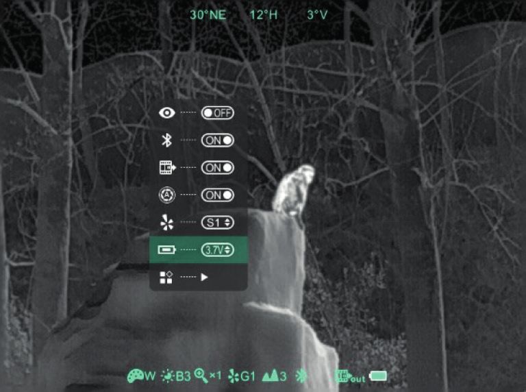
FASZINATION
       WÄRMEBILDTECHNIK

Liebe Kunden,
aus unserem Anspruch heraus, Ihnen stets technisch und qualita-
tiv führende Wärmebildoptiken anzubieten, finden Sie in unserem
neuen Programm Produkte mit modernster Technologie und
herausragenden Leistungsparametern.

Mit unserem Serviceversprechen, Ihnen im Falle einer Einsendung
innerhalb von zehn Werktagen Ihre Optik wieder zu retournieren,
sowie einer Garantie auf unsere Produkte von bis zu drei Jahren
bedanken wir uns für Ihr Vertrauen und wünschen ein kräftiges
Waidmannsheil!

Ihr LIEMKE-Team!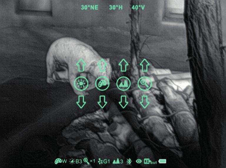
INHALT                                               D
                                                     E

01. TECHNISCHE DATEN����������������������� 4
02. LIEFERUMFANG���������������������������� 4
03. BEDIENELEMENTE ������������������������� 5
04. TASTENBELEGUNG ������������������������� 5
05. MENÜ-ÜBERSICHT ������������������������� 6
06. STROMVERSORGUNG���������������������� 8
07. EIN- UND AUSSCHALTEN ������������������� 8
08. BILDANPASSUNG ������������������������� 8
09. KALIBRIERUNG ���������������������������� 9
10. UC-MODUS ������������������������������� 9
11. VIDEOAUSGANG ������������������������� 9
12. KOMPASS UND WINKELMESSER ������������� 9
13. SPEICHERPLATZ ���������������������������� 10
14. FEHLPIXEL-KORREKTUR ���������������������� 10
15. E-ZOOM-EINSTELLUNGEN ������������������� 10
16. KALIBRIERUNG DES BEWEGUNGSSENSORS��� 11
17. EINRICHTUNG FÜR DIE VERWENDUNG IM
    VORSATZMODUS �������������������������� 11
18. REINIGUNG UND PFLEGE ������������������� 13
19. STÖRUNGSBESEITIGUNG ������������������� 13

                                                     2
                                                     –
                                                     3

MERLIN-50 · Bedienungsanleitung 08 / 2021
01. TECHNISCHE DATEN*
MODELL                                           Merlin-50

Detektor
Detektortyp                         Microbolometer; VOx ungekühlt
Auflösung (Pixel)                                640 x 512
Pixelgröße (μm)                                      12
Bildwiederholrate (Hz)                               50
NETD – kleinster darstellbarer
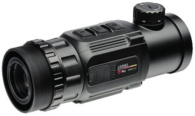
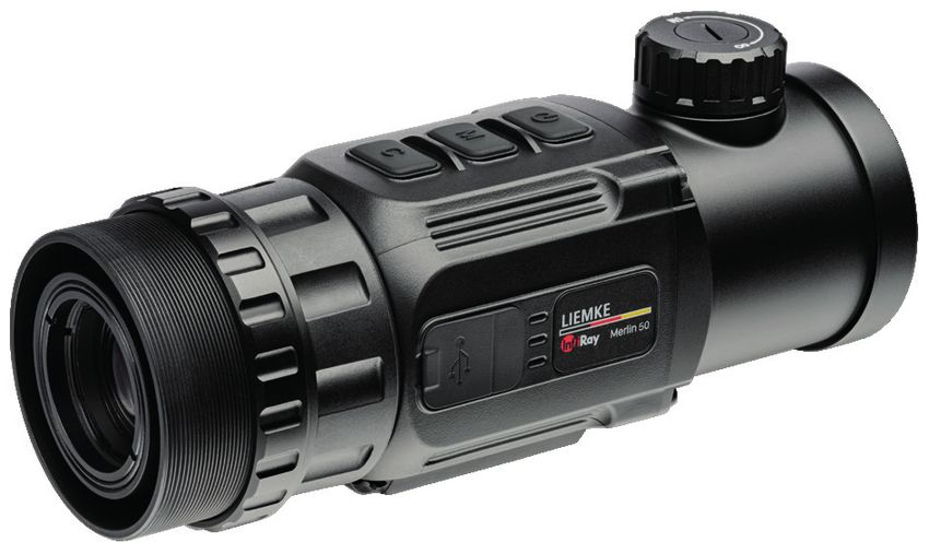
03. BEDIENELEMENTE D
E
01 02 03 04 05 06 07 08
11 10 09
01. Kollimator 07. Fokussierknopf
02. Gewinde für 08. Objektivschutzdeckel
Klemmadapter 09. Objektivlinse
03. Konterring 10. USB-C-Anschluss
04. Kalibriertaste 11. Batteriefach (auf der
05. Menütaste anderen Seite)
06. EIN/AUS-Taste
04. TASTENBELEGUNG
TASTE Funktion kurzer Druck langer Druck
EIN/AUS- Gerät ein-/
Taste (6) ausschalten
Stand-by ein /
aus
Schnellwahl- Auswahl zyklisch
menü
Hauptmenü Auswahl zyklisch
Bildverschiebe- Verschiebung Verschiebung
menü um 1 Pixel um 10 Pixel
Menütaste Schnellwahl- öffnet das Menü schließt das
(5) menü Menü
Umschalten der
Menüeinträge
Hauptmenü Verstellung des öffnet/schließt
Menüpunktes das Hauptmenü
Bildverschiebe- Auswahl zwi- speichert &
menü schen X/Y-Achse schließt das
Menü
Kalibrier- Sensor kalibriert stille Kalibrie-
taste (4) mit Verschluss rung mit manu-
ell aufgesetzter
Objektivkappe
Schnellwahl- Auswahl zyklisch
menü
Hauptmenü Auswahl zyklisch
Bildverschiebe- Verschiebung Verschiebung
menü um 1 Pixel um 10 Pixel
EIN/AUS- & Kompasskali- Startet die Kom-
Kalibrier- brierung passkalibrierung 4
taste
–
5
MERLIN-50 · Bedienungsanleitung 08 / 2021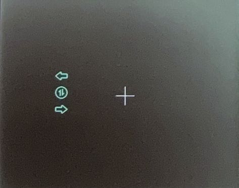
05. MENÜ-ÜBERSICHT
Schnellwahlmenü, Statuszeile und Menüpunkte

Hauptmenü, Seite 1

Hauptmenü, Seite 2

Schnellwahlmenü, Statuszeile und Menüpunkte                               D
                                                                          E
SYMBOL            Bedeutung

                  Bildschirm Helligkeitsstufen 1-4

                  Farbmodus: B (Black Hot), W (White Hot), R (Red Hot),
                  C (Falschfarben)

                  Bildschärfe – Stufen 1-4

                  Digitalzoom 1x/2x/4x

Hauptmenü, Menüpunkte

SYMBOL            Bedeutung

                  UC-Modus; Bildoptimierung für schlechte
                  Sichtverhältnisse
                  Bluetooth bereit

                  Video-Ausgang bereit

                  Speicherplatz Bildverschiebe-Koordinaten G1 bis G4

                  Batterietyp 3 bzw. 3.7 Volt

                  Automatische Sensor-Kalibrierung

                  Wechsel zur Seite 2

                  Menü zur Treffpunktkorrektur (Bildverschiebe-Menü)

                  Koordinaten für die Mitte des Zoom-Fensters auswählen

                  Fehlpixel-Korrektur

                  Werkseinstellung

                  Zurück zu Hauptmenü, Seite 1

Weitere Symbole

SYMBOL            Bedeutung

                  Verbleibende Batteriekapazität

                  Bluetooth Verbindung hergestellt

                  Video-Ausgang aktiviert

                  X/Y-Verstellung im Bildverschiebemenü                   6
                                                                          –
                                                                          7

MERLIN-50 · Bedienungsanleitung 08 / 2021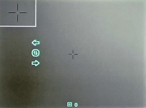
06. STROMVERSORGUNG
Bestücken Sie die Kamera mit zwei CR123-Batterien. Die korrekte
Polung ist im Innern des Batteriefachs (11) angegeben. Es können
sowohl Batterien, als auch Akkus (Typ 16340) verwendet werden.
Je nach verwendeter Nennspannung der Batterien, wählen Sie
(für eine korrekte Spannungsanzeige) im Hauptmenü           den
entsprechenden Eintrag (3 und 3.7 Volt) aus.
Wir empfehlen 3.7 V Akkus mit mindestens 700 mAh für maximale
Laufzeit.
> Achten Sie bitte darauf, stets Batteriepaare desselben Fabri-
    kats, mit gleicher Spannung und möglichst gleichem Ladezu-
    stand einzulegen.
Der Betrieb der Kamera ist auch über eine externe Stromversor-
gung, wie Powerbank oder KFZ-Strom möglich. Die Versorgung
über eingelegte Batterien wird bei externer Stromversorgung
automatisch überbrückt.
Akkus können nicht über den USB-Anschluss (10) geladen werden!

07. EIN- UND AUSSCHALTEN
>   Objektivschutzdeckel entfernen.
>   EIN/AUS-Taste (6) drei Sekunden lang gedrückt halten, um das
    Gerät einzuschalten.
>   Gerät nach der Benutzung ausschalten: Dazu die EIN/AUS-Tas-
    te (6) lang gedrückt halten.
    Auf dem Bildschirm erscheint ein Countdown, der von 5 bis 1
    zählt. Danach schaltet sich das Gerät aus.
    Wenn Sie die EIN/AUS-Taste (6) während des Countdowns
    loslassen, bleibt das Gerät eingeschaltet.
>   Um das Gerät während der Benutzung in den Stand-by-
    Zustand zu versetzen (Ausschalten des Display-Bildschirms),
    genügt ein kurzer Druck auf die EIN/AUS-Taste (6).
>   Ein erneuter kurzer Druck auf die EIN/AUS-Taste (6) weckt das
    Gerät wieder auf.

08. BILDANPASSUNG
Sie können im normalen Betrieb das Bild an die jeweiligen Um-
gebungsbedingungen und an Ihre Bedürfnisse anpassen. Dazu
stehen Ihnen über das Schnellwahlmenü – kurzer Druck auf die
Menütaste (5) – folgende Einträge zur Verfügung:
• Displayhelligkeit, Farbpalette, Schärfung und Digitalzoom
> Drücken Sie jeweils kurz die Menütaste (5), um die verschie-
    denen Bereiche auszuwählen und jeweils die EIN/AUS-Taste
    (6) bzw. Kalibriertaste (4), um den ausgewählten Punkt zu
    verändern.
09. KALIBRIERUNG                                                      D
                                                                      E
Das Merlin-50 kalibriert seinen Thermal-Sensor kurz nach dem Start
automatisch.
Ob während des Betriebs weiterhin eine automatische Kalibrie-
rung erfolgt, stellen Sie im Menüpunkt „Kalibrierung“ ein.
Bei Manueller Kalibrierung wird das Bild ausschließlich dann berei-
nigt, wenn Sie selbst auf die Kalibriertaste (4) drücken.
Wenn Sie während der Kalibrierung möglichst wenig Geräusche
verursachen wollen, können Sie über den langen Druck der Kali-
briertaste (4) einen Kalibriervorgang mit manuell vorgehaltenem
Objektivschutzdeckel durchführen. Das Geräusch des automati-
schen Verschlusses entfällt dann.
Die Kalibrierung ist erforderlich, wenn das Bild verstärkt Rauschen
und Strukturen anzeigt, die nichts mit der betrachteten Szene zu
tun haben.

10. UC-MODUS
Bei Witterungslagen mit hoher relativer Luftfeuchtigkeit entsteht
ein Schleier im Wärmebild. Mit dem zuschaltbaren Ultra-Clear-Mo-
dus (UC) kann dieser Schleier vermindert werden.
> Im Hauptmenü – langer Druck auf die Menütaste (5) – den
    entsprechenden Menüpunkt auswählen.
> Kurz auf die Menütaste (5) drücken, um den Menüpunkt
    umzustellen.

11. VIDEOAUSGANG
Nach Aktivierung der Video-Out-Funktion lässt sich das Bild über
das mitgelieferte USB-Kombi-Kabel analog im PAL- Format an
externe Monitore übertragen.

12. KOMPASS UND WINKELMESSER
Mittig am oberen Bildrand können Sie verschiedene Werte zur
Orientierung ablesen:
• Die Himmelsrichtung als Buchstabenkürzel und in Grad,
• den Neigungswinkel nach oben und unten (Vertikal),
• sowie den Neigungswinkel um die Waagerechte (Horizontal).
   Der Schütze spricht von Verkantung.

                                                                      8
                                                                      –
                                                                      9

MERLIN-50 · Bedienungsanleitung 08 / 2021
13. SPEICHERPLATZ
Wenn Sie das Merlin-50 im Vorsatzmodus verwenden, sehen Sie
am unteren Bildrand das aktuell gewählten Koordinaten-Paar.
Über das Bildverschiebe-Menü haben Sie die Möglichkeit, bis zu 4
verschiedene X/Y-Koordinaten-Paare zu definieren, die Sie beim
Abgleich zwischen Waffe, Tagsichtoptik und Nachtsichtvorsatz
ermitteln. Die Speicher (G1 bis G4) entsprechen dann zum Beispiel
verschiedenen Waffen, die Sie benutzen wollen.
Im Hauptmenü können Sie die Speicherplätze wechseln (ange-
zeigt durch ein kleines Dreieck).
14. FEHLPIXEL-KORREKTUR
Im normalen Betrieb kann es
manchmal vorkommen, dass
einzelne Sensorzellen (Pixel) des
Microbolometers falsche Werte
liefern oder auch komplett
ausfallen. In solchen Fällen
kann, ohne Präzisionsverlust
oder andere Nachteile, das
schadhafte Pixel durch eine
Berechnungsvorschrift „ausgeblendet“ werden. Dazu müssen Sie
dem Merlin-50 lediglich die genaue Position des defekten Pixels
bekannt geben.
Das geht ganz einfach mit dem folgenden Ablauf:
> Fehlpixel-Korrektur im Hauptmenü auswählen und öffnen.
> Kreuz mit der EIN/AUS-Taste (6) und der Kalibriertaste (4) auf
den Fehlpixel bewegen, bis der Punkt in der Kreuzmitte den
Fehlpixel abdeckt. Sie verschieben das Kreuz immer nur in der
X- oder in der Y-Achse (horizontal oder vertikal). Die Achse
ändern Sie mit der Menütaste (5). Durch einen längeren Druck
lässt sich das Kreuz in 10-Pixel-Schritten bewegen.
Ein kurzer Druck bewegt das Kreuz pixelweise.
> Liegt das Kreuz mittig auf dem Fehlpixel, drücken Sie die
EIN/AUS-Taste (6) und die Kalibriertaste (4) gleichzeitig, um den
Pixel auszublenden.
> Mit einem langen Druck der Menütaste (5) schließen Sie das
Menü.
15. E-ZOOM-EINSTELLUNGEN
In diesem Untermenü haben Sie
die Möglichkeit, die Mitte des
Zoom-Bereichs dort im Bild zu
definieren, wo es Ihnen gefällt.
Der Schütze sollte das
Zoom-Zentrum auf die Mitte des
Tagsicht-Absehens einstellen,
um auch bei höherer (digitaler)
Vergrößerung seine präzise
Treffpunktlage nicht zu verlieren.16. KALIBRIERUNG DES BEWEGUNGS- D
E
SENSORS
Der Kompass und die Lage-
sensoren müssen für den
Betrieb einmalig kalibriert
werden. Hierzu führen Sie bitte
die folgenden Schritte aus:
> Legen Sie das Gerät auf
eine glatte Tischplatte.
> EIN/AUS-Taste (6) und
Kalibriertaste (4) gleichzeitig
lang drücken.
Das nebenstehende Symbol
wird nun angezeigt.
> Das Merlin-50 auf der Tischplatte 5x im Uhrzeigersinn drehen.
> Objektivschutzdeckel auf das Objekt aufsetzen. Danach das
Merlin-50 auf das Objektiv stellen und ebenfalls 5x im Uhrzei-
gersinn rotieren.
> Anschließend das Merlin-50 in der Hand 5x um den Knopf
des Batteriefachs rotieren (Rückwärts-Salto vor dem Bauch
machen).
Nach ca. 30 Sekunden verschwindet das Achssymbol, die Senso-
rik ist nun kalibriert.
Durch langen Druck auf die Menütaste (5) kann der Prozess abge-
brochen werden.
17. EINRICHTUNG FÜR DIE VERWEN-
DUNG IM VORSATZMODUS
Sie benötigen für den Einsatz als Vorsatzgerät einen passenden,
separat erhältlichen Klemmadapter.
Für den waidgerechten Einsatz muss Ihre Kombination aus Waffe,
Tagsichtoptik und Nachtsichtvorsatz perfekt aufeinander abge-
stimmt sein. Die letzten Schritte dazu finden Sie in der untenste-
henden Anleitung:
Vorbereitung:
Verstellwert je 1 Klick = 1 Tastendruck
• 50 Meter: 1.2 cm Höhen- und Seitenverstellung
• 100 Meter: 2.4 cm Höhen- und Seitenverstellung
> Die Waffe wird mit der Tagsichtoptik auf die Einsatzdistanz
(i.d.R. 100m) eingeschossen.
> Das Zielfernrohr auf die kleinste Vergrößerung und, so vorhan-
den, den Parallaxeausgleich des Zielfernrohrs auf unendlich
(∞) stellen.
> Einen passenden Klemmadapter auf das Anschlussgewinde
(2) schrauben und den Konterring (3) fest gegen den Klem-
madapter ziehen. Achten Sie darauf, dass der Klemmhebel
seitlich oder oben liegt.
> Das Vorsatz-Gerät einschalten, gerade bis zum Anschlag auf 10
die Optik setzen und Klemmhebel schließen. –
11
MERLIN-50 · Bedienungsanleitung 08 / 2021> Wählen Sie VOR dem Aufruf des Verschiebe-Menüs denjeni-
gen Speicherplatz (G1 bis G4) aus, den Sie in der weiteren
Prozedur bearbeiten wollen. Eine nachträgliche Auswahl ist
nicht möglich.
Treffpunkt-Justage:
01. Probeschuss auf die vorher benutzte Distanz. Sollte der
Zielpunkt abweichen, können Sie die Treffpunktabweichung
ausmessen und im Verschiebe-Menü einstellen.
02. Wählen Sie dazu im Hauptmenü den Eintrag für das Bildver-
schiebe-Menü aus.
03. Wählen Sie durch Druck der Menütaste (5) zwischen Hö-
hen- (Y) und Seitenverstellung (X). Mit der EIN/AUS-Taste (6)
und Kalibriertaste (4) bewegen Sie das Bild entsprechend
der angezeigten Pfeilrichtung, bis das Bild entsprechend der
gemessenen Abweichung verstellt wurde.
Ein Tastendruck verschiebt das Bild um eine Pixelbreite, ein
längerer Druck um 10 Pixel. Die Werte können Sie direkt an den
Koordinaten ablesen.
04. Die Speicherung der Werte erfolgt durch einen langen Druck
auf die Menütaste (5).
05. Probeschuss/Gruppe setzen und Treffpunkt-Kontrolle durchfüh-
ren. Ggf. die Bildverschiebung wiederholen.
Nachbereitung:
> Vorsatzoptik abnehmen und den Zielpunkt über die Tagsich-
toptik mit einer Probe-Schussgruppe zu prüfen.
> Vorsatzoptik erneut aufsetzen und ebenfalls eine Gruppe auf
der Scheibe platzieren.
> Ist das Trefferbild stimmig, notieren Sie sich den Speicherplatz
(G1, G2, G3 oder G4) mit den entsprechenden X/Y-Koordina-
ten.
Wichtige Hinweise!
> Achten Sie unbedingt vor der Benutzung im Vorsatzmodus auf
eine ausreichend hohe Optikmontage.
• Es sollte stets ein Mindestabstand von ca. 10mm zwischen
Klemmadapter-Unterkante und Büchsenlauf gewährleistet
sein. Andernfalls können im Schuss Belastungen auftreten, die
zu Schäden am Gerät, des Zielfernrohrs, Ihrer Montage und
letztlich zu Ablagen führen können.
• Eine Kimme (offene Visierung) unter dem Merlin-50 kann
ebenfalls oben genannte Probleme zur Folge haben. Auch
hier ist der Mindestabstand von 10 mm einzuhalten.
• Die Verstellung des Bildschirms z.B. nach oben (EIN/ AUS-Taste
(6)), verlagert den Treffpunkt nach oben. Die Verstellung des
Bildschirms nach links (EIN/AUS-Taste (6)) verlagert den Treff-
punkt nach links.
• Die Klemmung der Vorsatzoptik muss straff auf dem Tubus des
Zielfernrohrs sitzen, d.h. die Optik kann nicht per Hand nach
vorne abgezogen werden. Zur Erhöhung der Klemmspannung
kann die Hebelkraft mit der Schraube am Klemmadapter
eingestellt werden.• Die Vorsatzoptik ist entsprechend der Anleitung auf die jeweili- D
ge vorgesehene Tagesoptik zu justieren bzw. einzuschießen. E
• Probeschüsse sind nach der Justierung, zur Sicherstellung der
gleichen Treffpunktablage, unabdingbar.
• Die Vorsatzoptik ist stets in der gleichen Position zu klemmen
(so wie diese justiert wurde). Hier helfen entsprechende Mar-
kierungen an der Vorsatzoptik sowie der Tagsichtoptik.
• Es ist anzumerken, dass eine Veränderung der Klemmposition
(horizontal oder vertikal) zu einer Veränderung der Treffpunkta-
blage führen kann!
• Bei aktivem Gebrauch der Optik (z. B. Pirsch) ist darauf zu ach-
ten, dass sich die Klemmposition der Vorsatzoptik, durch Stöße
etc. nicht verändert!
18. REINIGUNG UND PFLEGE
Sollte ihre Wärmebildkamera im täglichen Gebrauch Verschmut-
zungen aufweisen, können Sie diese mit einem weichen, fusselfrei-
en Tuch und ggf. mit etwas mildem, nicht scheuernden und nicht
korrodierenden Reinigungsmitteln säubern.
Besonders die optischen Flächen sind mit größter Vorsicht zu
reinigen, um Beschädigungen auszuschließen. Diese Maßnahmen
tragen wesentlich zum Werterhalt Ihres Merlin-50 bei.
19. STÖRUNGSBESEITIGUNG
Diese Übersicht führt einige Probleme auf, die bei der Benutzung
des Gerätes auftreten können.
> Führen Sie alle empfohlenen Prüfungen wie in der Tabelle
beschrieben durch.
> Falls ein Fehler auftritt, der nicht in der Tabelle Aufgeführt ist
oder Sie einen Fehler nicht selbst beheben können, sollte das
Gerät zur Reparatur an die zuständige Servicestelle überge-
ben werden.
Fehlfunktion Möglicher Grund Korrektur
Die Wärmebildka- Batterien sind zu Neue Batterien /Akkus
mera lässt sich nicht schwach. einlegen.
einschalten. Im Start-
Die Spannung der Power Bank nach-
vorgang schaltet externen Versorgung laden.
sich das Merlin nach reicht nicht aus. Passendes Netzteil
Einblendung des verwenden.
Startlogos wieder
aus.
Kann nicht über eine USB-Kabel ist beschä- USB-Kabel ersetzen.
externe Stromquelle digt.
betrieben werden.
Das Bild ist unscharf, Kalibrierung erfor- Führen Sie die Bildka-
mit dünnen senk- derlich librierung (C-Taste)
rechten Linien oder durch.
Schatten.
12
–
13
MERLIN-50 · Bedienungsanleitung 08 / 2021Fehlfunktion Möglicher Grund Korrektur
Geringe Bildqualität Diese Probleme können unter ungünstigen Wet-
/ verringerte Erken- terbedingungen eintreten (hohe Luftfeuchtig-
nungsreichweite. keit, Schneefall, Regen, Nebel, usw.).
Bei Temperaturen über dem Gefrierpunkt,
weisen die beobachteten Objekte (Umgebung
und Hintergrund) in der Regel eine höhere
Temperaturdifferenz auf.
Diese lässt sich vom Wärmebildgerät entspre-
chend kontrastreicher darstellen. Bei tiefen
Außentemperaturen kühlen die beobachteten
Objekte in etwa auf die gleiche Temperatur
ab, sodass der Temperaturkontrast erheblich
reduziert wird und die Bildqualität dadurch
leidet. Diese Eigenschaft ist physikalisch bedingt
und stellt keinen Defekt an der Wärmebildka-
mera dar.
Fehler im Vorsatzmodus
Die Treffpunktlage Anstelle der Bildver- Treffpunktlage ein-
lässt sich nicht schiebefunktion wurde stellen.
anpassen, die Werte im Hauptmenü die
werden nicht gespei- Pixelkorrektur oder das
chert. Menü für die Zoom-Ko-
ordinaten aktiviert.
Das Bild geht nach Batteriefachdeckel Deckel auf festen
dem Schuss aus. sitzt nicht korrekt. Sitz prüfen (Dichtung
darf von außen nicht
sichtbar sein).
Mindestabstand der Abstand überprüfen
Montage nicht einge- und korrigieren.
halten.
Klemmspannung des Klemmspannung
Adapters zu niedrig. erhöhen.
Treffpunktlage ist Klemmadapter und
nicht konstant. Montage auf festen
Sitz überprüfen.
Speicherplatz der Bild- Speicherplatz wählen.
verschiebekoordina-
ten falsch angewählt.
Der Parallaxeausgleich Wenn möglich, den
an der Zieloptik ist Parallaxeausgleich auf
nicht auf unendlich unendlich einstellen.
eingestellt. Wenn kein Parallaxe-
ausgleich verfügbar
ist, schauen Sie
möglichst mittig in die
Optik.
Mindestabstand der Abstand überprüfen
Montage nicht einge- und korrigieren.
halten.D
E
14
–
15
MERLIN-50 · Bedienungsanleitung 08 / 2021FASCINATION THERMAL IMAGING TECHNOLOGY Dear Customers, Our mission to always offer you thermal imaging optics that are at the forefront of technology and quality means that you will find products with state-of-the-art technology and outstanding performance parameters in our new range. With our service promise to return any optics you have sent in to you within ten working days, as well as a guarantee on our prod- ucts of up to three years, we would like to thank you for your trust and wish you good hunting! Your LIEMKE team!
CONTENT                                                         E
                                                                N

01. TECHNICAL DATA ������������������������� 18
02. SCOPE OF DELIVERY ���������������������� 18
03. CONTROLS ������������������������������� 19
04. KEY ASSIGNMENT ������������������������� 19
05. MENU OVERVIEW ������������������������� 20
06. POWER SUPPLY ���������������������������� 22
07. SWITCHING ON AND OFF������������������� 22
08. IMAGE ADJUSTMENT ���������������������� 22
09. CALIBRATION ���������������������������� 23
10. UC MODE ������������������������������� 23
11. VIDEO OUTPUT ���������������������������� 23
12. COMPASS AND PROTRACTOR ������������� 23
13. MEMORY LOCATION ���������������������� 24
14. BLIND PIXEL CORRECTION               ���������������� 24
15. E-ZOOM SETTINGS ������������������������� 24
16. CALIBRATION OF THE MOVEMENT SENSOR �� 25
17. SET UP FOR USE IN ATTACHMENT MODE������ 25
18. CLEANING AND CARE���������������������� 27
19. TROUBLESHOOTING ����������������������� 27

                                                                16
                                                                –
                                                                17

MERLIN-50 · Operating manual
                      Manual 08 / 2021
01. TECHNICAL DATA* MODEL Merlin-50 Detector Detector type Microbolometer; VOx uncooled Resolution (pixel) 640 x 512 Pixel size (μm) 12 Frame rate (Hz) 50 NETD – smallest measurable
03. CONTROLS                                                                E
                                                                            N
  01     02    03    04     05    06      07     08

                             11    10                            09

01.    Collimator                        07.   Focusing knob
02.    Thread for clamping               08.   Lens Cover
       adapter                           09.   Eyepiece lens
03.    Counter ring                      10.   USB Type-C Interface
04.    Calibration                       11.   Battery compartment (on
05.    Menu Button                             the other side)
06.    Power Button

04. KEY ASSIGNMENT
BUTTON        Function            Short press          Long press

Power                                                  Turning the
button (6)                                             device on/off
                                  Stand-by on/off
              Shortcut menu       Cyclic selection
              Main menu           Cyclic selection
              Image shift         Shift by 1 pixel     Shift by 10 pixels
              menu
Menu          Shortcut menu       Opens the menu       Closes the
Button (5)                                             menu
                                  Switching the
                                  menu items
              Main menu           Adjusting the        Opens/closes
                                  menu item            the main menu
              Image shift         Selection be-        Saves & closes
              menu                tween X/Y axis       the menu
Calibration                       Sensor calibrat-     Silent calibra-
(4)                               ed with shutter      tion with man-
                                                       ually attached
                                                       lens cap
              Shortcut menu       Cyclic selection
              Main menu           Cyclic selection
              Image shift         Shift by 1 pixel     Shift by 10 pixels
              menu
Power and Compass cali-                                Starts compass
Calibration bration                                    calibration

                                                                            18
                                                                            –
                                                                            19

MERLIN-50 · Operating Manual 08 / 2021
05. MENU OVERVIEW Quick select menu, status bar and menu items Main menu, page 1 Main menu, page 2
Quick select menu, status bar and menu items                                E
                                                                            N
SYMBOL            Meaning

                  Screen brightness levels 1-4

                  Colour mode: B (Black Hot), W (White Hot), R (Red Hot),
                  C (False Colours)

                  Sharpness – levels 1-4

                  Digital zoom 1x/2x/4x

Main menu, menu items

SYMBOL            Meaning

                  UC mode; image optimisation for poor
                  visibility conditions
                  Bluetooth ready

                  Video output ready

                  Memory location, image shift coordinates G1 to G4

                  Battery Type 3 / 3.7 Volt

                  Automatic sensor calibration

                  Change to page 2

                  Point of impact correction menu (image shift menu)

                  Select coordinates for the centre of the zoom window

                  Blind pixel correction

                  Factory settings

                  Back to main menu, page 1

More symbols

SYMBOL            Meaning

                  Remaining battery capacity

                  Bluetooth connected

                  Video output activated

                  X/Y adjustment in the image shift menu                    20
                                                                            –
                                                                            21

MERLIN-50 · Operating Manual 08 / 2021
06. POWER SUPPLY
Equip the camera with two CR123 batteries. The correct polarity
is indicated inside the battery compartment (11). Both batteries
and rechargeable batteries (type 16340) can be used. Depend-
ing on the nominal voltage of the batteries used, select (for
correct voltage display) the corresponding entry (3 and 3.7 volts)
in the main menu .
We recommend 3.7 V batteries with at least 700 mAh for maxi-
mum operating time.
> Please make sure to always insert pairs of batteries of the
same make and voltage that are charged to the same level
if possible.
The operation of the camera is also possible over an external
power supply, such as powerbank or car power. Supply via
inserted batteries is automatically bridged in the event of external
power supply.
Batteries cannot be charged via the USB interface (10)!
07. SWITCHING ON AND OFF
> Remove the lens cover.
> Long press the Power button (6) for three seconds to switch
the unit on.
> Switch off the unit after use: To do this, long press the Power
button (6).
A countdown appears on the screen, counting down from 5
to 1. The unit then switches off.
If you release the Power button (6) during the countdown, the
unit remains switched on.
> To put the unit into stand-by mode (switch off the display
screen) during use, briefly press the Power button (6).
> Pressing the Power button (6) briefly again will wake up the
unit.
08. IMAGE ADJUSTMENT
In normal operation, you can adjust the picture to the respective
ambient conditions and to your needs. The following entries are
available via the quick selection menu – short press on the menu
key (5):
• Display brightness, colour palette, sharpness and digital zoom
> Briefly press the menu button (5) to select the different areas
and the Power button (6) or calibration button (4) to change
the selected item.09. CALIBRATION E
N
The Merlin-50 automatically calibrates its thermal sensor shortly
after start-up.
You can set whether automatic calibration should be performed
during operation in the menu item “Calibration”.
With manual calibration, the image is only cleaned when you
press the calibration button (4) yourself.
If you want to cause as little noise as possible during calibration,
you can perform calibration with the lens cover held up manually
by long-pressing the calibration button (4). The automatic shutter
noise is then omitted.
Calibration is necessary if the image shows increased noise and
structures that have nothing to do with the scene being viewed.
10. UC MODE
In weather conditions with high relative humidity, a haze appears
in the thermal image. With the switchable Ultra-Clear mode (UC),
this haze can be reduced.
> In the main menu – long press on the menu button (5) – select
the corresponding menu item.
> Briefly press the menu button (5) to change the menu item.
11. VIDEO OUTPUT
After activating the video-out function, the picture can be
transmitted analogue in PAL format to external monitors via the
supplied USB combination cable.
12. COMPASS AND PROTRACTOR
In the centre of the upper edge of the screen you can read off
various values for orientation:
• The cardinal direction as a letter abbreviation and in degrees,
• the angle of inclination upwards and downwards (Vertical),
• and the angle of inclination about the horizontal (Horizontal)
axis.
The shooter refers to oblique angle shots.
22
–
23
MERLIN-50 · Operating Manual 08 / 202113. MEMORY LOCATION
When using the Merlin-50 in attachment mode, you will see
the currently selected pair of coordinates at the bottom of the
screen.
Via the image shift menu you can define up to 4 different X/Y
coordinate pairs, which you determine when aligning the rifle,
day vision optics and night vision attachment. The memories (G1
to G4) then correspond to different weapons you want to use, for
example.
You can change the memory locations in the main menu (shown
by clicking a small triangle).
14. BLIND PIXEL CORRECTION
During normal operation,
individual sensor cells (pixels)
of the microbolometer may
provide incorrect values or
even fail completely. In such
cases , the defective pixel can
be “hidden” by a calculation
rule without loss of precision
or other disadvantages. All you
have to do is tell the Merlin-50 the exact position of the defective
pixel.
This can be done very easily as follows:
> Select and open Blind pixel correction in the main menu.
> Move the cross to the blind pixel with the Power button (6)
and the calibration button (4) until the dot in the centre of
the cross covers the blind pixel. You only ever move the cross
in the X or Y axis (horizontally or vertically). Change the axis
with the menu button (5). By pressing longer, the cross can be
moved in steps of 10 pixels.
A short press moves the cross pixel by pixel.
> If the cross is centred on the blind pixel, press the
Power button (6) and the calibration button (4) simultaneously
to hide the pixel.
> Close the menu with a long press on the menu button (5).
15. E-ZOOM SETTINGS
In this submenu you have
the option to define the centre
of the zoom area where you
like it in the picture.
The shooter should set the
zoom centre to the centre of
the day vision reticle so as not
to lose their precise point of
impact even at higher (digital)
magnification.16. CALIBRATION OF THE MOVEMENT E
N
SENSOR
The compass and the position
sensors must be calibrated
once for operation. To do this,
please follow the steps below:
> Place the unit on an even
table top.
> Long press the Power button
(6) and the calibration but-
ton (4) simultaneously.
The adjacent symbol is now
displayed.
> Turn the Merlin-50 clockwise 5 times on the table top.
> Put the lens cover on the object. Then place the Merlin-50 on
the lens and also rotate clockwise 5 times.
> Then rotate the Merlin-50 in your hand 5 times around the
battery compartment button (flip it backwards in front of your
stomach).
After approx. 30 seconds the axis icon disappears and the sensor
system is calibrated.
The process can be cancelled by a long press on the menu
button (5).
17. SET UP FOR USE IN ATTACHMENT
MODE
For use as an attachment, you need a suitable clamping adapter,
which is available separately.
Your combination of rifle, day vision optics and night vision attach-
ment must be perfectly matched to each other for expert hunting
use. The final steps can be found in the instructions below:
Preparation:
Adjustment value per 1 click = 1 push of the button
• 50 metres: 1.2 cm height and side adjustment
• 100 metres: 2.4 cm height and side adjustment
> The rifle is zeroed with the day vision optics at the operational
distance (usually 100 m).
> Set the scope to the lowest magnification and, if available, set
the parallax compensation of the scope to infinity (∞).
> Screw a suitable clamping adapter onto the connection
thread (2) and pull the counter ring (3) firmly against the
clamping adapter. Make sure that the clamping lever is on the
side or on top.
> Switch on the attachment, place it straight on the optics as far
as it will go and close the clamping lever.
> BEFORE calling up the shift menu, select the memory location
(G1 to G4) that you want to edit in the process. You will not be
able to make a selection later on. 24
–
25
MERLIN-50 · Operating Manual 08 / 2021Adjusting the point of impact:
01. Test shot at the previously used distance. If the aiming point
deviates, you can measure the deviation in point of impact
and adjust it in the shift menu.
02. To do this, select the entry for the image shift menu in the main
menu.
03. Select between height (Y) and side (X) adjustment by pressing
the menu button (5). Use the Power button (6) and calibration
button (4) to move the image according to the direction of
the arrow displayed until the image has been adjusted ac-
cording to the measured deviation.
Pressing the button shifts the image by one pixel width, a longer
press by 10 pixels. You can read the values directly from the
coordinates.
04. The values are saved by a long press on the menu button (5).
05. Set test shot/group and carry out point of impact check. If
necessary, repeat the image shift.
Follow-up:
> Remove the attachment optics and check the aiming point
via the day vision optics with a test firing group.
> Put on the attachment optics again and also place a group
on the shooting target.
> If the hit pattern is consistent, note down the memory location
(G1, G2, G3 or G4) with the corresponding X/Y coordinates.
Important notes!
> Make absolutely sure that the optics are mounted sufficiently
high before using them in the attachment mode.
• There should always be a minimum distance of approx.
10 mm between the lower edge of the clamping adapter
and the barrel of the rifle. Otherwise, stresses can occur in
the shot that can cause damage to the unit, the scope, your
mount and ultimately result in shifting.
• A rear sight (open sights) under the Merlin-50 can also result
in the above-mentioned problems. Here, too, the minimum
distance of 10 mm must be observed.
• Adjusting the screen e.g. upwards (Power button (6)) shifts
the point of impact upwards. Adjusting the screen to the left
(Power button (6)) shifts the point of impact to the left.
• The clamping of the attachment optics must sit tightly on
the tube of the scope, i.e. the optics cannot be pulled off
to the front by hand. To increase the clamping tension, the
lever force can be adjusted with the screw on the clamping
adapter.
• The attachment optics must be adjusted to the respective
intended day optics according to the instructions.
• Test shots are indispensable after adjustment to ensure the
same point of impact.
• The attachment optics must always be clamped in the same
position (as they were adjusted). Appropriate markings on the
attachment optics as well as the daytime optics help here.• It should be noted that changing the clamping position E
(horizontally or vertically) can lead to a change in the point of N
impact!
• When actively using the optics (e.g. stalking), make sure that
the clamping position of the attachment optics does not
change due to impacts etc.!
18. CLEANING AND CARE
If your thermal imaging camera becomes dirty during daily use,
you can clean it with a soft, lint-free cloth and, if necessary, with
some mild, non-abrasive and non-corrosive cleaning agent.
The optical surfaces in particular must be cleaned with the utmost
care to avoid damage. These measures contribute significantly to
preserving the value of your Merlin-50.
19. TROUBLESHOOTING
This overview lists some problems that may occur when using the
unit.
> Carry out all recommended checks as described in the table.
> If an error occurs that is not listed in the table or if you cannot
rectify an error yourself, the unit should be handed over to the
responsible service centre for repair.
Malfunction Possible reason Correction
The thermal imager Batteries are too Insert new batteries/re-
cannot be switched weak. chargeable batteries.
on. In the starting
Insufficient external Recharge the
process, the Merlin supply voltage. powerbank.
switches off again Use a suitable mains
after the start logo adapter.
has been displayed.
Can‘t be powered USB cable is Replace USB cable.
by an external pow- damaged.
er source.
The image is blurred, Calibration needed Calibrate the image
with thin vertical (C-button).
lines or shadows.
Low image quality / These problems can occur under adverse
reduced detection weather conditions (high humidity, snowfall, rain,
range. fog, etc.).
At temperatures above freezing, the observed
objects (surroundings and background) usually
have a higher temperature difference.
This can be shown by the thermal imager by
setting the contrast higher. At low outdoor
temperatures, the observed objects cool down
to approximately the same temperature, so
that the temperature contrast is considerably
reduced and the image quality suffers as a re-
sult. This characteristic is due to physical reasons
and does not represent a defect in the thermal
imager.
26
–
27
MERLIN-50 · Operating Manual 08 / 2021Malfunction Possible reason Correction
Error in attachment mode
The point of impact Instead of the image Set the point of
cannot be adjusted shift function, pixel impact.
and the values are correction or the zoom
not saved. coordinates menu was
activated in the main
menu.
The image goes out Battery compartment Check cover for prop-
after the shot. cover is not seated er seating (seal must
correctly. not be visible from the
outside).
Minimum mounting Check and correct
distance not ob- distance.
served.
Insufficient adapter Increase clamping
clamping voltage. voltage.
Point of impact is not Check that the clamp-
constant. ing adapter and
assembly are fixed in
position.
Memory location of Select memory
the image shift co- location.
ordinates incorrectly
selected.
The parallax compen- If possible, set the par-
sation on the target allax compensation to
optics is not set to infinity.
infinity. If parallax compensa-
tion is not available,
look at the centre of
the lens as much as
possible.
Minimum mounting Check and correct
distance not ob- distance.
served.E
N
28
–
29
MERLIN-50 · Operating Manual 08 / 2021FASCINACIÓN
TERMOGRAFÍA
Estimados clientes,
basándonos en nuestra filosofía de ofrecerles constantemente
óptica termográfica de calidad y tecnología punteras, en
nuestro nuevo programa incluimos productos con la más
moderna tecnología y extraordinarias prestaciones.
Con la promesa de nuestro servicio técnico de devolverle su
óptica en diez días laborables en caso de que nos la remita, así
como una garantía de hasta tres años sobre nuestros productos,
agradecemos su confianza y le deseamos una buena caza.
El equipo de LIEMKE.ÍNDICE E
S
01. DATOS TÉCNICOS ������������������������� 32
02. VOLUMEN DE SUMINISTRO����������������� 33
03. ELEMENTOS DE CONTROL������������������� 33
04. FUNCIÓN DE LOS BOTONES ���������������� 34
05. VISTA GENERAL DEL MENÚ ���������������� 35
06. ALIMENTACIÓN ELÉCTRICA ���������������� 37
07. ENCENDER Y APAGAR���������������������� 37
08. AJUSTE DE LA IMAGEN �������������������� 37
09. CALIBRACIÓN ���������������������������� 38
10. MODO UC ������������������������������� 38
11. SALIDA DE VÍDEO ������������������������� 38
12. BRÚJULA Y MEDIDOR DE ÁNGULO ���������� 38
13. POSICIÓN DE MEMORIA ������������������� 39
14. CORRECCIÓN DE PÍXELES DEFECTUOSOS ���� 39
15. AJUSTES DEL E-ZOOM ���������������������� 40
16. CALIBRACIÓN DEL SENSOR DE MOVIMIENTO� 40
17. DISPOSITIVO PARA EL USO EN
EL MODO DE ACOPLAMIENTO ������������� 40
18. LIMPIEZA Y CUIDADO ���������������������� 42
19. SOLUCIÓN DE PROBLEMAS ���������������� 43
30
–
31
MERLIN-50
MERLIN-50 ·· Manual
Manual de
de instrucciones
instrucciones 08
08//2021
202101. DATOS TÉCNICOS*
MODELO Merlin-50
Detector
Tipo de detector Microbolómetro; VOx no
refrigerado
Resolución (píxeles) 640 x 512
Tamaño de píxel (μm) 12
Velocidad de actualización de la 50
imagen (Hz)
NETD – menor diferencia de tem-02. VOLUMEN DE SUMINISTRO E
S
• Cámara termográfica • Pilas CR123 (2 unds.)
Merlin-50 • Tapa de protección del
• Cable de salida de video/ objetivo
USB • Tapa del colimador
• Bolsa de transporte con • Manual de instrucciones
asas
03. ELEMENTOS DE CONTROL
01 02 03 04 05 06 07 08
11 10 09
01. Colimador 08. Tapa de protección del
02. Rosca para el adaptador objetivo
03. Anillo de fijación 09. Lente del objetivo
04. Botón de calibración 10. Conexión USB-C
05. Botón de menú 11. Compartimento para
06. Botón de encendido/ las pilas (en el lado
apagado contrario)
07. Botón de enfoque
32
–
33
MERLIN-50 · Manual de instrucciones 08 / 202104. FUNCIÓN DE LOS BOTONES
BOTÓN Funcionamiento pulsación corta pulsación larga
Botón de Conexión y
ENCENDI- desconexión
DO/APA- Stand-by encen-
GADO (6) dido/apagado
Menú de selec- Opciones dispo-
ción rápida nibles se repiten
cíclicamente
Menú principal Opciones dispo-
nibles se repiten
cíclicamente
Menú de des- Desplazamiento Desplazamiento
plazamiento de en 1 píxel en 10 píxeles
imagen
Botón de Menú de selec- Abre el menú Cierra el menú
menú (5) ción rápida
Cambiar las
opciones del
menú
Menú principal Ajuste de la op- Abre/cierra el
ción de menú menú principal
Menú de des- Selección entre Guarda y cierra
plazamiento de el eje X/Y el menú
imagen
Botón de Calibración del Calibración
calibra- sensor con cierre silenciosa con
ción (4) la tapa del ob-
jetivo colocada
manualmente
Menú de selec- Opciones dispo-
ción rápida nibles se repiten
cíclicamente
Menú principal Opciones dispo-
nibles se repiten
cíclicamente
Menú de des- Desplazamiento Desplazamiento
plazamiento de en 1 píxel en 10 píxeles
imagen
Botón de Calibración de Inicia la cali-
ENCENDI- la brújula bración de la
DO/APA- brújula
GADO
y de cali-
bración05. VISTA GENERAL DEL MENÚ E
S
Menú de selección rápida, línea de estado y opciones del menú
Menú principal, página 1
Menú principal, página 2
34
–
35
MERLIN-50 · Manual de instrucciones 08 / 2021Menú de selección rápida, línea de estado y opciones del menú
SÍMBOLO Significado
Niveles de brillo 1-4 de la pantalla
Modo de color: B (negro intenso), W (blanco intenso), R
(rojo intenso), C (falso color)
Nitidez – niveles 1-4
Zoom digital 1x/2x/4x
Menú principal, opciones del menú
SÍMBOLO Significado
Modo UC; optimización de la imagen para
condiciones de visibilidad desfavorables
Bluetooth listo
Salida de vídeo lista
Posición de memoria para las coordenadas de despla-
zamiento de imagen G1 hasta G4
Tipo de pila 3 ó 3,7 V
Calibración automática del sensor
Cambiar a la página 2
Menú para la corrección del punto de impacto (menú
para desplazamiento de la imagen)
Seleccionar las coordenadas para el centro de la
ventana de zoom
Corrección de píxeles defectuosos
Ajustes de fábrica
Volver al menú principal, página 1
Otros símbolos
SÍMBOLO Significado
Capacidad restante de la pila
Conexión Bluetooth establecida
Salida de vídeo activada
Ajuste X/Y en el menú de desplazamiento de imagen06. ALIMENTACIÓN ELÉCTRICA E
S
Coloque en la cámara dos pilas CR123. En el interior del com-
partimento para las pilas (11) se indica la polaridad correcta. Se
pueden utilizar tanto pilas como pilas recargables (tipo 16340). En
función de la tensión nominal de las pilas utilizadas, seleccione
en el menú principal la entrada correspondiente (3 y 3,7
voltios) (para una indicación correcta de la tensión).
Para obtener la máxima autonomía, recomendamos utilizar pilas
de 3,7 V con una capacidad mínima de 700 mAh.
> Asegúrese de colocar siempre pares de pilas de la misma
marca, con el mismo voltaje y, si es posible, con el mismo
estado de carga.
La cámara también puede funcionar a través de una fuente de
alimentación externa como, por ejemplo, una batería externa
portátil o la corriente del coche. La alimentación a través de las
pilas insertadas se anula automáticamente en caso de utilizarse
una alimentación externa.
¡Las pilas no pueden cargarse a través del puerto USB (10)!
07. ENCENDER Y APAGAR
> Retirar la tapa de protección del objetivo.
> Mantener pulsado el botón de ENCENDIDO/APAGADO (6)
durante tres segundos para encender el aparato.
> Apague el aparato después de su uso: Para ello, mantenga
pulsado el botón de ENCENDIDO/APAGADO (6).
En la pantalla aparece una cuenta atrás de 5 a 1. A continua-
ción, el aparato se apaga.
Si suelta el botón de ENCENDIDO/APAGADO (6) durante la
cuenta atrás, el aparato sigue encendido.
> Para pasar el aparato al estado de espera durante su uso (se
apaga la pantalla), pulse brevemente el botón de ENCENDI-
DO/APAGADO (6).
> Pulse de nuevo el botón de ENCENDIDO/APAGADO (6) breve-
mente para reactivar el aparato.
08. AJUSTE DE LA IMAGEN
Durante el funcionamiento normal, puede ajustar la imagen a
las condiciones ambientales concretas y a sus necesidades. Para
ello, a través del menú de selección rápida, pulsando brevemen-
te la tecla de menú (5), están disponibles las siguientes opciones:
• brillo de la pantalla, paleta de colores, sensibilidad y zoom
digital
> Pulse brevemente el botón de menú (5) cada vez para selec-
cionar los distintos campos y el botón de ENCENDIDO/APAGA-
DO (6) o el botón de calibración (4) cada vez para cambiar
el punto seleccionado.
36
–
37
MERLIN-50 · Manual de instrucciones 08 / 202109. CALIBRACIÓN
La cámara Merlin-50 calibra automáticamente su sensor térmico
poco después de la puesta en marcha.
En la opción de menú "Calibración" puede ajustar si debe
continuar realizándose la calibración automática durante el
funcionamiento.
Con la calibración manual, la imagen sólo se depura si pulsa el
botón de calibración (4).
Si quiere hacer el menor ruido posible durante la calibración,
puede efectuar la calibración manteniendo la tapa del obje-
tivo delante del objetivo y manteniendo pulsado el botón de
calibración (4). De este modo, se suprime el ruido del obturador
automático.
La calibración es necesaria si la imagen presenta un aumento
de ruido y estructuras que no tienen nada que ver con la escena
que se está viendo.
10. MODO UC
En condiciones meteorológicas con alta humedad relativa, se
forma una neblina en la imagen térmica. Esta neblina puede
reducirse con el modo ultra transparente UC (Ultra-Clear) conmu-
table.
> En el menú principal, pulsando prolongadamente el botón de
menú (5), seleccione la opción del menú correspondiente.
> Pulse brevemente el botón de menú (5) para cambiar la
opción del menú.
11. SALIDA DE VÍDEO
Tras activar la función de salida de vídeo, es posible transmitir la
imagen analógica en formato PAL a monitores externos a través
del cable USB combinado suministrado.
12. BRÚJULA Y MEDIDOR DE ÁNGULO
En el centro del borde superior de la pantalla se pueden consul-
tar diversos valores de orientación:
• la dirección cardinal representada por letras y en grados,
• el ángulo de inclinación hacia arriba y hacia abajo (Vertical),
• así como el ángulo de inclinación alrededor de la horizontal
(Horizontal).
El tirador lo conoce como desalineamiento.13. POSICIÓN DE MEMORIA E
S
Cuando utilice la Merlin-50 en el modo de acoplamiento, verá en
la parte inferior de la pantalla el par de coordenadas actual-
mente seleccionado.
A través del menú de desplazamiento de la imagen tiene la po-
sibilidad de definir hasta 4 pares de coordenadas X/Y diferentes,
que se determinan al alinear el arma, la óptica de visión diurna
y el accesorio de la mira nocturna. En ese caso, por ejemplo, las
memorias (G1 a G4) corresponden a las diferentes armas que
quiera utilizar.
En el menú principal puede cambiar las posiciones de memoria
(indicadas por un pequeño triángulo).
14. CORRECCIÓN DE
PÍXELES DEFECTUOSOS
Durante el funcionamiento
normal, a veces puede ocurrir
que algunas celdas del sensor
(píxeles) del microbolómetro
proporcionen valores incorrec-
tos o incluso que fallen por
completo. En estos casos, y sin
que por ello se pierda precisión
u otros inconvenientes, es
posible "ocultar" el píxel defectuoso mediante una regla de
cálculo. Para ello, basta con indicar a Merlin-50 la posición
exacta del píxel defectuoso.
Esto puede hacerse fácilmente siguiendo los siguientes pasos:
> Seleccione y abra la Corrección de píxeles defectuosos en el
menú principal.
> Mueva la cruz con el botón de ENCENDIDO/APAGADO (6) y
el botón de calibración (4) hacia el píxel defectuoso hasta
que el punto en el centro de la cruz cubra el píxel defectuo-
so. La cruz sólo puede moverse en el eje X o Y (horizontal o
verticalmente). El eje puede cambiarse usando el botón de
menú (5). Si mantiene pulsado el botón, puede mover la cruz
en pasos de 10 píxeles.
Una pulsación breve mueve la cruz píxel por píxel.
> Cuando la cruz esté centrada sobre el píxel defectuoso, pulse
simultáneamente el botón de
ENCENDIDO/APAGADO (6) y el botón de calibración (4) para
ocultar el píxel.
> Al pulsar prolongadamente el botón de menú (5) se cierra el
menú.
38
–
39
MERLIN-50 · Manual de instrucciones 08 / 202115. AJUSTES DEL E-ZOOM
En este submenú tiene la
opción de definir el centro del
área de zoom (aumento) en la
posición que desee en la
imagen.
El tirador debería situar el
centro del zoom en el centro
de la retícula de la mira diurna
para no perder su punto de
impacto preciso incluso con un aumento mayor (digital).
16. CALIBRACIÓN DEL SENSOR DE
MOVIMIENTO
Para su funcionamiento, la
brújula y los sensores de
posición deben calibrarse una
vez. Para ello, siga los siguientes
pasos:
> Coloque el aparato sobre
una mesa lisa.
> Mantenga pulsados simultá-
neamente el botón de
ENCENDIDO/APAGADO (6)
y el botón de calibración
(4).
Se mostrará el símbolo mostrado al lado.
> Gire la Merlin-50 en el sentido de las agujas del reloj 5 veces
sobre la mesa.
> Coloque la tapa del objetivo en el objeto. A continuación,
coloque la Merlin-50 en el objetivo y gire también 5 veces en
el sentido de las agujas del reloj.
> A continuación, gire la Merlin-50 en su mano 5 veces alrede-
dor del botón del compartimento de las pilas (voltear comple-
tamente hacia atrás delante de su vientre).
Después de aproximadamente 30 segundos el símbolo de los ejes
desaparece y la sensórica está calibrada.
Puede cancelar el proceso con una pulsación larga del botón
de menú (5).
17. DISPOSITIVO PARA EL USO EN
EL MODO DE ACOPLAMIENTO
Para utilizarlo como accesorio de acoplamiento, necesitará un
adaptador de sujeción adecuado, que puede adquirirse por
separado.
Para utilizar el dispositivo correctamente para la caza, es nece-
sario que la combinación del rifle, la óptica de visión diurna y el
accesorio de visión nocturna estén perfectamente adaptados
entre sí. En las instrucciones siguientes se indican los pasos finales
para hacerlo:Preparación: E
Valor de ajuste por clic = 1 pulsación de botón S
• 50 metros: ajuste de altura y lateral de 1,2 cm
• 100 metros: ajuste de altura y lateral de 2,4 cm
> El rifle se dispara con la óptica de visión diurna a la distancia
operativa (normalmente 100 m).
> Ajuste el visor al menor aumento y, si está disponible, ajuste la
compensación de paralaje del visor a infinito (∞).
> Enrosque un adaptador de sujeción adecuado en la rosca de
conexión (2) y apriete el anillo de fijación (3) firmemente con-
tra el adaptador de sujeción. Asegúrese de que la palanca
de sujeción quede en el lateral o en la parte superior.
> Encienda el accesorio, colóquelo recto hasta el tope de la
óptica y cierre la palanca de sujeción.
> ANTES de acceder al menú de desplazamiento, seleccione
la posición de memoria (G1 a G4) que desea editar en el
procedimiento posterior. No es posible realizar una selección
a posteriori.
Ajuste del punto de impacto:
01. Efectuar un disparo de prueba a la distancia utilizada ante-
riormente. Si el blanco se desvía, puede medir la desviación
de punto de impacto y ajustarlo en el menú de desplaza-
miento.
02. Para ello, seleccione en el menú principal la opción para el
menú de desplazamiento de la imagen.
03. Pulse el botón de menú (5) para elegir entre el ajuste de
altura (Y) y el ajuste lateral (X). Utilice el botón de ENCENDI-
DO/APAGADO (6) y el botón de calibración (4) para mover la
imagen según la dirección de la flecha mostrada hasta que
la imagen se haya ajustado según la desviación medida.
Pulsar una vez el botón desplaza la imagen en un píxel, una pul-
sación más prolongada la desplaza en un ancho de 10 píxeles.
Puede leer los valores directamente desde las coordenadas.
04. Para guardar los valores, pulse prolongadamente el botón de
menú (5).
05. Fijar el disparo de prueba/grupo y realizar la comprobación
del punto de impacto. Si fuese necesario, repita el desplaza-
miento de la imagen.
Comprobación posterior:
> Retire la óptica de acoplamiento y compruebe el blanco a
través de la óptica de visión diurna con un grupo de disparo
de prueba.
> Vuelva a colocar la óptica de acoplamiento y sitúe también
un grupo en el disco.
> Si el esquema de acierto en el blanco es correcto, anote la
posición de memoria (G1, G2, G3 o G4) con las correspon-
dientes coordenadas X/Y.
40
–
41
MERLIN-50 · Manual de instrucciones 08 / 2021¡Indicaciones importantes! > Antes de usar la óptica en modo de acoplamiento, asegúrese de que la óptica esté montada a una altura suficiente. • Siempre debe asegurarse una distancia mínima de unos 10 mm entre el borde inferior del adaptador y el cañón. De lo contrario, pueden producirse cargas durante el disparo, que pueden provocar daños en el dispositivo, el visor, su montaje y, en última instancia, adherencias. • Un alza debajo de la cámara Merlín-50 también puede cau- sar los problemas mencionados anteriormente. También aquí debe mantenerse una distancia mínima de 10 mm. • Al ajustar la pantalla, por ejemplo, hacia arriba (botón EN- CENDIDO/APAGADO (6)), se desplaza el punto de impacto hacia arriba. Al desplazar la pantalla hacia la izquierda (botón de ENCENDIDO/APAGADO (6)) se desplaza el punto de impacto hacia la izquierda. • La sujeción de la óptica de acoplamiento debe quedar bien firme en el tubo del visor, es decir, que la óptica no debe poder extraerse con la mano. Para aumentar la fuerza de apriete, es posible ajustar la fuerza de la palanca mediante el tornillo del adaptador. • La óptica de acoplamiento debe ser ajustada a la respectiva óptica de día o dispararse de acuerdo con las instrucciones. • Es esencial efectuar disparos de prueba después del ajuste para asegurar la misma posición del punto de impacto. • La óptica de acoplamiento debe estar siempre sujeta en la misma posición (como fue ajustada). A este respecto, son de ayuda las marcas pertinentes en las ópticas de acoplamiento y en la óptica de visión diurna. • ¡Debe tenerse en cuenta que un cambio en la posición de sujeción (horizontal o vertical) puede producir un cambio en el punto de impacto! • ¡Al utilizar activamente la óptica (por ejemplo, caza al ace- cho), asegúrese de que la posición de fijación de la óptica de acoplamiento no cambie debido a golpes, etc.! 18. LIMPIEZA Y CUIDADO Si su cámara termográfica se ensucia durante el uso diario, puede limpiarla con un paño suave y sin pelusas y, si es nece- sario, con algún producto de limpieza suave, no abrasivo y no corrosivo. En especial, deben limpiarse con el mayor cuidado las superficies de las lentes para evitar que se dañen. Estas medidas contri- buyen significativamente a mantener el valor de su cámara Merlin-50.
Sie können auch lesen