PH - UND REDOX ELEKTRODEN - PH - AND REDOX ELECTRODES PH - ET REDOX ÉLECTRODES PH - Y REDOX ELECTRODOS - XYLEM ANALYTICS
←
→
Transkription von Seiteninhalten
Wenn Ihr Browser die Seite nicht korrekt rendert, bitte, lesen Sie den Inhalt der Seite unten
BETRIEBSSANLEITUNG
                             OPERATING INSTRUCTIONS
                                      MODE D’EMPLOI
                            MANUAL DE INSTRUCCIONES

pH – UND REDOX ELEKTRODEN
pH - And Redox electrodes
pH - et Redox électrodes
pH - y Redox electrodos

WIDERSTANDSTHERMOMETER
resistance thermometers
thermomètre à résistances
termómetro de resistencia
INHALTSVERZEICHNIS

Sicherheitshinweise (ATEX 100a)                                Seite 3
Betriebsanleitung pH – und Redox – Elektroden                  Seite 6
Betriebsanleitung Widerstandsthermometer                       Seite 10
Technische Daten ATEX Sensoren                                 Seite 13
EG – Konformitätserklärung                                     Seite 54

Safety Information (ATEX 100a)                                 page 16
Instruction manual pH and Redox - electrodes                   page 19
Instruction manual resistance thermometers                     page 23
Technical data ATEX sensors                                    page 26
EC – decalaration of conformity                                page 54

Avis de sécurité (ATEX 100a)                                   page 29
Mode d’emploi pH – et Redox électrodes                         page 32
Mode d’emploi thermomètre à résistances                        page 36
Caractéristiques techniques senseurs ATEX                      page 39
CE – déclaration de conformité                                 page 54

Instrucctiones de seguridad (ATEX 100a)                        página 42
Manual de instrucciones pH – y Redox electrodos                página 45
Manual de instrucciones termómetro de resistencia              página 49
Especificaciones tèchniqas sensores ATEX                       página 52
CEE – declaracion de conformidad                               página 54

Aktualität bei Drucklegung
Fortschrittliche Technik und das hohe Qualitätsniveau unserer Geräte werden durch eine
ständige Weiterentwicklung gewährleistet. Daraus können sich evtl. diverse Abweichungen
zwischen dieser Betriebsanleitung und Ihrem Gerät ergeben. Irrtümer können wir nicht ganz
ausschließen. Haben Sie deshalb bitte Verständnis, dass aus den Angaben, Abbildungen
und Beschreibungen keine juristischen Ansprüche abgeleitet werden können.

Hinweis
Eine möglicherweise aktuellere Version dieser Betriebsanleitung finden Sie Internet unter
www.si-analytics.com.

Copyright © Mainz 2013, SI Analytics GmbH
Nachdruck - auch auszugsweise - nur mit schriftlicher Genehmigung
der SI Analytics GmbH, Mainz.

Printed in Germany

2
Sicherheitshinweise für Errichtung und Betrieb elektrochemischer Sensoren in
explosionsgefährdeten Bereichen gemäß Richtlinie 94/9/EG (ATEX 100a)
        Diese Sicherheitshinweise gelten für die folgenden chemischen Sensoren
                             der Firma SI Analytics GmbH.
            Elektrodentyp                                  Kopfform    Temperaturfühler
PH-EINSTABMESSKETTE AQUALINE         AL 51-xxx pHT VP        VP            Pt 1000
PH-EINSTABMESSKETTE PROCESSLINE      PL 80-xxx pH           Koax              -
PH-EINSTABMESSKETTE PROCESSLINE      PL 81-xxx pHT          SMEK           Pt 1000
PH-EINSTABMESSKETTE PROCESSLINE      PL 81-xxx pHT VP        VP            Pt 1000
PH-EINSTABMESSKETTE PROCESSLINE      PL 82-xxx pHT          SMEK            Pt 100
PH-EINSTABMESSKETTE PROCESSLINE      PL 82-xxx pHT VP        VP             Pt 100
REDOX MESSKETTE       PROCESSLINE    PL 89-xxx Pt           Koax              -
PH-EINSTABMESSKETTE PROCESSLINE      PL PETR-xxx            SMEK           Pt 1000
PH-EINSTABMESSKETTE PROCESSLINE      PL PETR-xxx VP          VP            Pt 1000
PH-EINSTABMESSKETTE STEAMLINE        SL 80-xxx pH           Koax              -
PH-EINSTABMESSKETTE STEAMLINE        SL 81-xxx pHT          SMEK           Pt 1000
PH-EINSTABMESSKETTE STEAMLINE        SL 81-xxx pHT VP        VP            Pt 1000
PH-EINSTABMESSKETTE STEAMLINE        SL 82-xxx pHT          SMEK            Pt 100
PH-EINSTABMESSKETTE STEAMLINE        SL 82-xxx pHT VP        VP             Pt 100
PH-EINSTABMESSKETTE STEAMLINE        SL 83-xxx pHT          SMEK         NTC 30KΏ
PH-EINSTABMESSKETTE STEAMLINE        SL 83-xxx pHT VP        VP          NTC 30KΏ
REDOX-MESSKETTE       STEAMLINE      SL 89- xxx Pt          Koax              -
PH-EINSTABMESSKETTE HD               H 8381-HD              Koax              -
PH-GLASELEKTRODE HD                  H 1171-HD              Koax              -
PH-GLASELEKTRODE HD                  S 1171-HD              Koax              -
PH-GLASELEKTRODE HD                  L 1181-HD              Koax              -
PH-GLASELEKTRODE HD                  H 1181-HD              Koax              -
PH-GLASELEKTRODE HD                  S 1181-HD              Koax              -
PH-GLASELEKTRODE HD                  H 1191-HD              Koax              -
PH-GLASELEKTRODE HD                  H 2781-HD              Koax              -
PH-GLASELEKTRODE HD                  S 2781-HD              Koax              -
PLATIN-EINSTABMESSKETTE HD           Pt 8281-HD             Koax              -
PLATIN-EINSTABMESSKETTE HD           Pt 7781 HD             Koax              -
PLATINELEKTRODE HD                   Pt 1801-HD             Koax              -
SILBER-EINSTABMESSKETTE HD           AGS 8281 HD            Koax              -
BEZUGSELEKTRODE HD                   B 1181 HD               Pin              -
BEZUGSELEKTRODE HD                   B 1981 HD               Pin              -
WOLFRAMELEKTRODE HD                  Wo 1101-HD             Koax              -
PH-EINSTABMESSKETTEHD                H 7381 HD              Koax              -
PH-EINSTABMESSKETTEHD                H 7381-xxx-T100 VP      VP             Pt 100
PH-EINSTABMESSKETTEHD                H 7381-xxx-T1000 VP     VP            Pt 1000
PH-EINSTABMESSKETTE HD               H 8281-T100 HD         SMEK            Pt 100
PH-EINSTABMESSKETTE HD               H 8281-xxx-T100 VP      VP             Pt 100
PH-EINSTABMESSKETTE HD               H 8281-T1000 HD        SMEK           Pt 1000
PH-EINSTABMESSKETTE HD               H 8281xxx-T1000 VP      VP            Pt 1000
PH-EINSTABMESSKETTE HD               L 7781 HD              Koax              -
PH-EINSTABMESSKETTE HD               A 7781-xxx-T100 VP      VP             Pt 100
PH-EINSTABMESSKETTE HD               A 7781-xxx-T1000 VP     VP            Pt 1000
PH-EINSTABMESSKETTE HD               L 8281 HD              Koax              -
PH-EINSTABMESSKETTE HD               H 8181 HD              Koax              -
PH-EINSTABMESSKETTE HD               H 8281 HD              Koax              -
PH-EINSTABMESSKETTE HD               H 8481 HD              Koax              -
PH-EINSTABMESSKETTE HD               PET 50-xxx HD          SMEK           Pt 1000
PH-EINSTABMESSKETTE HD               PET 50-xxx VP           VP            Pt 1000

                                                                                          3
Elektrodentyp Kopfform Temperaturfühler WIDERSTANDSTHERMOMETER HD W 2021 HD SMEK PT 100 WIDERSTANDSTHERMOMETER HD W 2021 VP VP PT 100 WIDERSTANDSTHERMOMETER HD W 2161 HD SMEK Pt 1000 WIDERSTANDSTHERMOMETER HD W 2161 VP VP Pt 1000 WIDERSTANDSTHERMOMETER HD W 2081 HD SMEK Pt 100 WIDERSTANDSTHERMOMETER HD W 2081 VP VP Pt 100 Einsatzgebiet: Die Prozesssensoren dienen der Messung von pH-Wert, Redox Potentialen und/oder der Temperatur von Prozessmedien. Elektrische Anschlussdaten: Sensorstromkreise in Zündschutzart Eigensicherheit EEx ia IIC Höchstwerte der Summe: Für Sensoren mit Temperaturfühler. Temp. Klasse Umgebungstemperatur [°C] Uo [V] Io [mA] Po [mW] T6 ≤ 40 ≤ 12 ≤ 30 ≤ 50 T4 ≤ 40 ≤ 15 ≤ 80 ≤ 110 T3 ≤ 40 ≤18 ≤ 170 ≤ 200 Die wirksame innere Induktivität und Kapazität sind vernachlässigbar klein. Für Sensoren ohne Temperaturfühler. Temp. Klasse Umgebungstemperatur [°C] Uo [V] Io [mA] Po [mW] T6 ≤ 60 ≤18 ≤ 170 ≤ 200 Die wirksame innere Induktivität und Kapazität sind vernachlässigbar klein. Alle Stromkreise einschließlich des Schirmleiters und Erde sind aus sicherheitstechnischer Sicht auch als galvanisch miteinander verbunden anzusehen. Für die Errichtung und den Betrieb gibt es darüber hinaus die folgenden speziellen Vorgaben: • Der Explosionsschutz ist gewährleistet im Rahmen der atmosphärischen Bedingungen für einen Druck von absolut 80 kPa bis 110 kPa und eine Umgebungstemperatur von -20°C bis 60°C. Abweichend davon, sind die Sensoren mit Temperaturfühler für eine Obergrenze von 40°C zertifiziert. • Bei einem Einsatz außerhalb der atmosphärischen Bedingungen muss der Explosionsschutznachweis im Rahmen des Explosionsschutzdokumentes vom Betreiber geführt werden. • Für die Beständigkeit des Betriebsmittels gelten die üblichen Herstellerangaben. • Die Prozesssensoren werden mechanisch geschützt eingebaut, z.B. mittels geeigneter Armaturen oder durch räumliche Anordnung. • Über den gesamten Verlauf des eigensicheren Stromkreises ist ein hochzuverlässiger Potentialausgleich zu errichten. • Die Behandlung des Schirmleiters ist der Betriebsanleitung des verwendeten zugehörigen Betriebsmittels zu entnehmen. • Für den Fall, dass Maßnahmen gegen Überspannungen ergriffen werden müssen (Blitzschutz), ist der Schirmleiter mit einzubeziehen. • Risiken elektro- und thermochemischer Aktivität im Falle des Zusammentreffens von äußerem Medium mit den sensorinternen Elektrolyten/ Materialien bei Zerstörung des Glaskörpers, werden von Hersteller und Betreiber in eigener Verantwortung ausgeschlossen. 4
Installation
Bitte prüfen Sie vor dem ersten Einsatz Ihren chemischen Sensor auf eventuelle durch den
Transport entstandene Schäden. Stellen Sie Schäden fest, schicken Sie uns den Sensor
bitte umgehend zur Überprüfung.
Weitere Hinweise finden Sie im Prozess-Elektroden-Katalog von SI Analytics sowie in der
Bedienungsanleitung Ihres Messumformers.
Warnung:
Die oben angeführten chemischen Sensoren dürfen in ständig, langzeitig oder
häufig explosions-gefährdeten Bereichen (Kategorie 1) eingesetzt werden. Vor der
Installation muss der Installationsort auf seine Explosionsgefährdung hin beurteilt
und die Eignung der chemischen Sensoren festgestellt werden.
Warnung:
Eine falsche Installation oder Handhabung des chemischen Sensors kann den
Explosionsschutz beeinträchtigen und damit zur Zündung einer explosionsfähigen
Atmosphäre führen. Daher sind folgende Punkte bei einem Einsatz in
explosionsgefährdeten Bereichen strikt einzuhalten:
- Die Installation des chemischen Sensors in explosionsgefährdeten Bereichen darf
nur durch elektrotechnische Fachkräfte entsprechend den einschlägigen
Vorschriften und den elektrischen Anschlussdaten dieser Sicherheitshinweise
erfolgen.
- Die Installation, Inbetriebnahme und der Betrieb dieser Geräte sind entsprechend
den Anweisungen in der jeweiligen Betriebsanleitung durchzuführen.
- Die Schutzart IP 67 wird sichergestellt durch eine entsprechend fachgerechte
Montage, den Einsatz der HD Scheibe und die Verwendung von unbeschädigten O-
Ringen.
Achtung:
Bei der Installation des chemischen Sensors sind dessen technische Daten zu
beachten.
- Als Anschlusskabel an den Messumformer ist für den chemischen Sensor ein
Kabel zu verwenden, welches für den Anschluss an eine Klemmleiste eines
Messumformers mit hochohmigem pH-Eingang vorbereitet ist. Alle weiteren
Informationen entnehmen Sie bitte der Betriebsanleitung des Messumformers.
- Beim Einschrauben des Sensors ist darauf zu achten, dass das zulässige
Anzugsdrehmoment von 3,5 Nm nicht überschritten wird.
- Beim Anschluss des Sensorkabels muss sichergestellt werden, dass eine
einwandfreie Kontaktierung des Schirmleiters des Sensorkabels mit dem
Potentialausgleich der Anlage hergestellt wird.
- Die Belegung der Steckkontakte des chemischen Sensors finden Sie in der
Betriebsanleitung des jeweiligen chemischen Sensors
Version: SicherheitshinweiseATEXElektroden_d_130724.doc
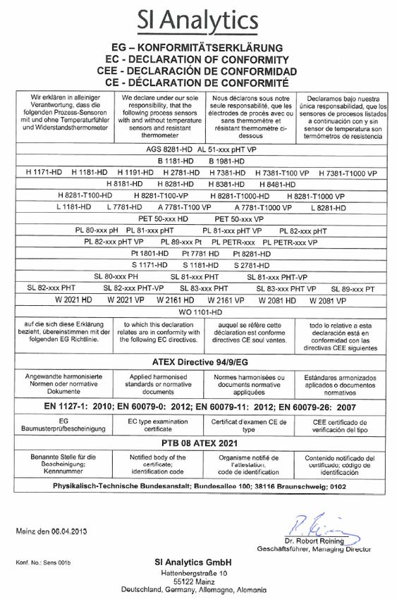
5Elektroden-Steckkopf
In Koax-, SMEK- oder
VP-Ausführung
HD-Dichtung
Diaphragma
pH-Glasmembran
Die abgebildete Elektrode ist ein Beispieltyp
Betriebsanleitung für
pH - und Redox-Elektroden
für die Prozess - und Umwelttechnologie
Auch mit integriertem Temperaturfühler
6pH - und Redox – Elektroden
Anwendungsbereich
• Zur Langzeitüberwachung und Grenzwertkontrolle von Prozessen in der Chemischen
Industrie, Biotechnologie, Lebensmittelindustrie und Pharmazie
• Für die Wasseraufbereitung und -überwachung z.B. in Abwasserreinigungsanlagen,
Neutralisationsanlagen oder von Grund-und Oberflächengewässern
Der Anwendungsbereich ist abhängig von der Elektrodengruppe.
pH-Messung
Der pH-Wert ist ein Maß für die Aktivität der Wasserstoffionen in einer wässrigen Lösung d.h.
für den sauren oder basischen Charakter einer Lösung. H+-Ionen bewirken einen
Potentialsprung an der Innen- und Außenseite der Glasmembran. Über die Ag/AgCl-
Refernzsysteme wird die Potentialdifferenz als Messsignal zum Elektroden-Steckkopf
abgeleitet. Die so entstandene Spannung (mV) wird mittels Messumformer entsprechend der
NERNSTschen Gleichung in ein pH-Signal umgewandelt.
Vorbereitung und Allgemeines
Befindet sich über Membran/Pt-Sensor und Diaphragma eine Wässerungskappe, so wird sie
entfernt. Sie enthält Aufbewahrungslösung (Typ L 911). Die Elektrode ist messbereit.
Trocken aufbewahrte Elektroden werden 24 Stunden in Aufbewahrungslösung gewässert
und anschließend durch eine Kalibrierung bzw. durch eine Messung in Redox - Pufferlösung
überprüft. Sollte die Elektrode dabei zu große Abweichnungen zeigen, ist sie zu entsorgen.
Im Elektrolytraum des Bezugssystems fehlende Elektrolytlösung wird nachgefüllt. Bitte
achten Sie auf die für die jeweilige Elektrode bestimmte Kaliumchloridkonzentration.
Bei wartungsarmen Elektroden mit verfestigtem Elektrolyten wie z. B. Gel-Füllung, Duralid
oder REFERID®-System erübrigt sich das Nachfüllen. Die Wässerung in
Aufbewahrungslösung ist bei diesen Elektroden besonders wichtig.
Messeinrichtung und Einbauhinweise
Der pH-Sensor ist Teil einer Messeinrichtung bestehend aus:
• pH-Elektrode
• Messumformer
• Eintauch-, Durchfluss- oder Wechselarmatur
• Messkabel
Bitte beachten Sie die Bedienungsanleitung des Messumformers, der Armatur sowie den
Belegungsplan des Anschlusskabels.
Die Elektroden sind für den Einbau über Kopf nicht geeignet. Der Einbauwinkel beträgt
mindestens 15° gegen die Horizontale.
Vor dem Einbau der pH-Elektrode ist das Einschraubgewinde auf Verschmutzung und
Gängigkeit zu kontrollieren.
Schrauben Sie die Elektrode mit max. 3,5 Nm („handfest“), wie in der Anleitung der Armatur
beschrieben, ein.
Verbinden Sie die Elektrode und den Messumformer mit dem dafür vorgesehenen
Anschlusskabel. Beachten Sie dabei den Belegungsplan des Anschlusskabels.
Beachten Sie für den Einbau der Sensoren die jeweiligen gültigen technischen Daten der
Armatur.
Elektrische Anschlussdaten
Beachten Sie beim Anschluss des Sensors an den Messumfomer die vom Hersteller
angegebenen elektrischen Anschlussdaten.
7pH - und Redox – Elektroden Messen des pH-Wertes Beachten Sie zum Kalibrieren und Messen bitte auch die Gebrauchsanleitung der Messeinrichtung. Um Verfälschungen der Messergebnisse zu minimieren, sind Elektroden, die unter extremen Bedingungen oder an den Grenzen der spezifizierten Einsatzbereiche eingesetzt werden, entsprechend häufiger zu kalibrieren. Für eine exakte Kalibrierung empfehlen wir den Einsatz unserer heißdampf-sterilisierten, zertifizierten Puffer nach DIN 19266 in Doppelspießampullen. Verwenden Sie immer nur frische Pufferlösungen. Messen der Redoxspannung Bei Metall-Einstabmessketten wird standardmäßig ein Ag/AgCl-Bezugssystem verwendet. Eine Kalibrierung wird nicht durchgeführt. Zur Überprüfung stehen Redox-Prüflösungen zur Verfügung. Lagerung und Wartung Elektroden sollten zwischen 0 und 40°C gelagert werden. In Abhängigkeit von den Lagerbedingungen (Temperatur und Luftfeuchtigkeit) kann die Aufbewahrungslösung in der Wässerungskappe frühzeitig austrocknen. Diese ist darum immer rechtzeitig nachzufüllen, um ein Austrocknen der Elektrode zu verhindern Der Elektrolyt muss bei pH- Einstabmessketten/ Redox-Messketten und Bezugselektroden gelegentlich aufgefüllt oder erneuert werden. Kristalle im Elektrolytraum können durch Erwärmung im Wasserbad aufgelöst werden. Die Elektrolytlösung sollte anschließend erneuert werden. Reinigung Verschmutzungen an Membran, Pt-Sensor und Diaphragma führen zu Messabweichungen. Diese können wie folgt entfernt werden: • Beläge mit verdünnten Mineralsäuren (z.B. verd. Salzsäure) • organische Verschmutzungen mit geeigneten Lösungsmitteln oder Laugen • Fette mit Tensidlösungen oder Alkohol • Proteine mit salzsaurer Pepsinlösung (Reinigungslösung L 510) Bei der Reinigung ist zu beachten: • Die Elektrode nach der Reinigung mit destilliertem Wasser abspülen, nicht trocken reiben • Von außen verstopfte Keramik-Diaphragmen werden durch vorsichtiges Abreiben mit feinem Sandpapier oder einer Diamantfeile wieder funktionsfähig. Die pH-Glasmembran darf dabei nicht verkratzt werden! • Platin-Diaphragmen dürfen nicht mechanisch behandelt werden. Einer chemischen Reinigung (z.B. mit verd. Salzsäure) kann ein Freispülen folgen (z.B. Absaugen). • Schliffdiaphragmen werden durch leichtes Anheben und anschließendes Aufstecken der Schliffhülse auf den Schliffkern gereinigt. • Die Glasmembran kann durch Abreiben mit einem ethanolgetränkten, fusselfreien Tuch gereinigt werden. • Beim Einsatz von aggressiven Reinigungsmitteln, Schutzbrille und Schutzhandschuhe tragen. • Nach der Reinigung sollte die Messkette mindestens 1h in 3M KCl-Lösung aufbewahrt werden. Qualität Jede Elektrode muss die strengen Qualitätsanforderungen der Endprüfung erfüllen. Die Le- bensdauer ist stark abhängig von den Einsatzbedingungen. Extreme Bedingungen wie z. B. hohe oder häufig wechselnde Temperaturen, starke Säuren und Laugen, proteinhaltige oder 8
pH - und Redox – Elektroden
stark verschmutzte Lösungen oder Elektrodengifte wie Sulfid, Bromid und Iodid verkürzen
die Lebensdauer. Flusssäure, Natronlauge und heiße Phosphorsäure greifen Glas an.
Hinweis für den Einsatz in Explosionsgefährdeten Bereichen
ATEX Kennzeichnung: ATEX II 1/2G Ga/Gb Ex ia IIC T3/T4/T6. Zulassung gemäß EG
Baumusterprüfbescheinigung: PTB 08ATEX2021.
Sicherheitshinweis
Das Dokument „Sicherheitshinweise für Errichtung und Betrieb elektrochemischer Sensoren
in explosionsgefährdeten Bereichen gemäß der Richtlinie 94/9/EC (ATEX 100a)“ ist zu
beachten.
Weitere Zulassungen und Zertifikate
TÜV-Zertifikat, Druckfestigkeit 12 bar bei dreifacher Sicherheit.
Technische Daten
Bitte beachten Sie das Dokument „Technische Daten ATEX Sensoren“.
SMEK und VP Steckerbelegung:
(Aufsicht auf den Elektrodensteckkopf)
SMEK- Stecker VP Stecker
1: Seele 1 A: Seele 1
2: ohne Belegung B: Bezugs.Elektr. 1
3: ohne Belegung C: nicht vorhanden
4: Temp. Sensor Pt 100/Pt 1000 D: nicht vorhanden
5: Temp. Sensor Pt 100/Pt 1000 E: Temp. Sensor Pt 100/Pt 1000
6: Bezugs Elektrode 1 F:. Temp. Sensor Pt 100/Pt 1000
G: nicht vorhanden
H: nicht vorhanden
Weitere Informationen
Weitere Hinweise finden Sie im Prozess-Elektrodenkatalog von SI Analytics.
Technische Änderungen vorbehalten.
Version: GA_ProzesspHRedoxATEX_d__130724.doc
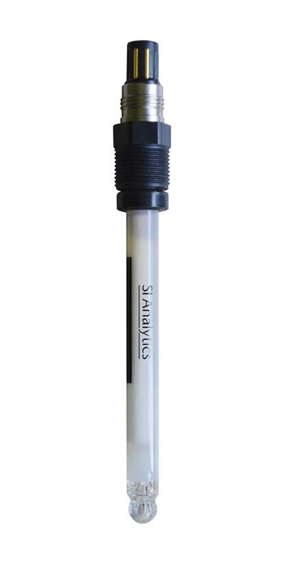
9VP-/SMEK-
HD-Dichtung
Pt-Ring (nur bei W 2161 HD)
Temperatur-Sensor
Die abgebildete Elektrode ist ein Beispieltyp
Betriebsanleitung für
Widerstandsthermometer
10Widerstandsthermometer
Anwendungsbereich
Die Widerstandsthermometer mit Platinring-Hilfselektrode dienen der
Temperaturkompensation bei industriellen Messungen. Der Platinring der W 2161 HD kann
je nach Bedarf unterschiedliche Aufgaben erfüllen:
• Als Redox-Elektrode, wenn die Bezugselektrode einer bereits installierten pH-
Einstabmesskette als Referenz zur Verfügung steht.
• Als Erdungselektrode in schlecht leitenden Medien, Kunststoffbehältern, etc.
• Als Hilfselektrode, wie sie zur Sensorüberwachung benötigt wird.
Messen der Temperatur
Den Temperaturfühler zur Messung mindestens 10 mm tief in die Messlösung eintauchen.
Messeinrichtung und Einbauhinweise
Das Widerstandsthermometer ist Teil einer Messeinrichtung bestehend aus:
• Widerstandsthermometer
• Messumformer
• Eintauch-, Durchfluss-, oder Wechselarmatur
• Messkabel
Bitte beachten Sie die Bedienungsanleitung des Messumformers, der Armatur sowie den
Belegungsplan des Anschlusskabels.
Vor dem Einbau des Widerstandsthermometers ist das Einschraubgewinde auf
Verschmutzung und Gängigkeit zu kontrollieren.
Schrauben Sie das Widerstandsthermometer mit max. 3,5 Nm ein („handfest“).
Beachten Sie für den Einbau der Widerstandsthermometer die jeweiligen gültigen
technischen Daten der Armatur.
Elektrische Anschlussdaten
Beachten Sie beim Anschluss des Widerstandsthermometers an den Messumfomer die vom
Hersteller angegebenen elektrischen Anschlussdaten.
Lagerung und Wartung
Die Widerstandsthermometer sollten zwischen 0 und 40°C gelagert werden.
Reinigung
Verschmutzungen auf dem Widerstandsthermometer führen zu Messabweichungen und
können wie folgt entfernt werden:
• Beläge mit verdünnten Mineralsäuren (z.B. verd. Salzsäure)
• organische Verschmutzungen mit geeigneten Lösungsmitteln oder Laugen
• Fette mit Tensidlösungen oder Alkohol
• Eiweiß mit salzsaurer Pepsinlösung (Reinigungslösung L 510)
Bei der Reinigung ist zu beachten:
• Das Widerstandsthermometer nicht mit abrasiven Mitteln, z.B. Scheuermilch,
Schmirgelpapier o.ä. behandeln.
• Das Widerstandsthermometer nach der Reinigung immer mit destilliertem Wasser
abspülen.
• Beim Einsatz von aggressiven Reinigungsmitteln, Schutzbrille und Schutzhandschuhe
tragen
11Widerstandsthermometer
Qualität
Jedes Widerstandsthermometer muss die strengen Qualitätsanforderungen der Endprüfung
erfüllen. Die Lebensdauer ist stark abhängig von den Einsatzbedingungen. Flusssäure,
heiße Phosphorsäure und Natronlauge greifen Glas an.
Hinweis für den Einsatz in Explosionsgefährdeten Bereichen:
ATEX Kennzeichnung: ATEX II 1/2G Ga/Gb Ex ia IIC T3/T4/T6
Zulassung gemäß EG Baumusterprüfbescheinigung:
PTB 08ATEX2021.
Sicherheitshinweis:
Das Dokument „Sicherheitshinweise für Errichtung und Betrieb elektrochemischer Sensoren
in explosionsgefährdeten Bereichen gemäß der Richtlinie 94/9/EC (ATEX 100a)“ ist zu
beachten.
Weitere Zulassungen und Zertifikate
TÜV-Zertifikat: Druckfestigkeit 12 bar bei dreifacher Sicherheit.
Technische Daten
Einsatzbereich: -30 ... + 135°C
Einbaulänge: 120 mm
Schaftdurchmesser: 12 mm
Anschluss: Schraubsteckkopf mit Einbaugewinde PG 13,5
Sensor: Pt 100 bei W 2081 HD, W 2021 HD Pt 1000 bei W 2161 HD
SMEK und VP Steckerbelegung
(Aufsicht auf den Elektrodensteckkopf)
SMEK- Stecker VP Stecker
1 und 5: interne Brücke A und F: interne Brücke
2 und 4: interne Brücke B: nicht vorhanden
3:Platinring-Hilfselektrode C und E: interne Brücke
bei der W 2161 HD D: Platinring-Hilfselektrode
4: Temp. Sensor Pt 100/Pt 1000 bei der W 2161 HD
5: Temp. Sensor Pt 100/Pt 1000 E: Temp. Sensor Pt 100/Pt 1000
6: ohne Belegung F: Temp. Sensor Pt 100/Pt 1000
G: nicht vorhanden
H: nicht vorhanden
Weitere Informationen
Weitere Hinweise finden Sie im Prozess-Elektrodenkatalog von SI Analytics.
Technische Änderungen vorbehalten.
Version: BA_WidThermATEX_d_130724.doc
12Technische Daten ATEX-Sensoren
Membran- Membran- Temperatur
Einsatzbereich Nullpun Druck Einsatz- Schaft- Ø Einbaulänge Temperatur-
Sensor glas widerstand [M Einsatzbereich Kopf Diaphragma Elektrolyt
[pH] kt [pH] bereich [bar] material [mm] [mm] fühler
Sensor Ω] [°C]
AGS 8281 HD Silbersulfid - 2…13 - 1-12 0...140 Glas 12 120 - Koax KPG-Ringspalt Referid
AL 51-xxx pHT VP A 300 0...14 7,0 1-12 -5...130 Glas 12 120;225;325;360;425 Pt1000 VP Loch DURALID
B 1181 HD - - 2…12 - 1-12 0...50 Glas 12 120 - Pin Keramik Gel KCl ges.
B 1981 HD - - 2…13 - 1-12 0...100 Glas 12 120 - Pin KPG-Ringspalt Referid
H 1171 HD H 400 0...14 7,0 1-12 0...140 Glas 12 120 - Koax - -
H 1181 HD H 300 0...14 7,0 1-12 0...135 Glas 12 120 - Koax - -
H 1191 HD H 2000 0...14 7,0 1-12 0...135 Glas 12 120 - Koax - -
H 2781 HD H 500 0...14 7,0 1-12 0...135 Glas 12 120 - Koax - -
H 7381 HD H 400 0...14 7,0 1-12 0...140 Glas 12 120 - Koax Keramik Gel KCl ges.
H 7381-xxx-T100 VP H 400 0...14 7,0 1-12 0...140 Glas 12 120;225;325;360;425 Pt 100 VP Keramik Gel KCl ges.
H 7381-xxx-T1000 VP H 400 0...14 7,0 1-12 0...140 Glas 12 120;225;325;360;425 Pt 1000 VP Keramik Gel KCl ges.
H 8181 HD H 400 2...13 7,0 1-12 0...100 Glas 12 170 - Koax KPG-Ringspalt Referid
H 8281 HD H 400 2...13 7,0 1-12 0...100 Glas 12 120 - Koax KPG-Ringspalt Referid
H 8281-xxx T100 HD H 400 2...13 7,0 1-12 0...100 Glas 12 120;225;325;360;425 Pt 100 SMEK KPG-Ringspalt Referid
H 8281-xxx -T100 VP H 400 2...13 7,0 1-12 0...100 Glas 12 120;225;325;360;425 Pt 100 VP KPG-Ringspalt Referid
H 8281-xxx T1000 HD H 400 2...13 7,0 1-12 0...100 Glas 12 120;225;325;360;425 Pt 1000 SMEK KPG-Ringspalt Referid
H 8281-xxx -T1000 VP H 400 2...13 7,0 1-12 0...100 Glas 12 120;225;325;360;425 Pt 1000 VP KPG-Ringspalt Referid
H 8381 HD H 400 2...13 7,0 1-12 0...100 Glas 12 120 - Koax KPG-Ringspalt Referid
H 8481 HD H 400 2...13 7,0 1-12 0...100 Glas 12 225 - Koax KPG-Ringspalt Referid
L 1181 HD A 200 0...12 7,0 1-12 -30...+80 Glas 12 120 - Koax - -
L 7781 HD A 200 2...12 7,0 1-12 -5...+80 Glas 12 120 - Koax Keramik Gel KCl ges.
A 7781-xxx-T100 VP A 200 2...12 7,0 1-12 -5...+80 Glas 12 120;225;325;360;425 - VP Keramik Gel KCl ges.
A 7781-xxx-T1000 VP A 200 2...12 7,0 1-12 -5...+80 Glas 12 120;225;325;360;425 - VP Keramik Gel KCl ges.
L 8281 HD A 400 2...12 7,0 1-12 -5...+80 Glas 12 120 - Koax KPG-Ringspalt Referid
PET 50-xxx HD A 500 2...13 7,0 1-12 0...100 Glas 12 120;225;325;360;425 Pt 1000 SMEK Loch Referid
PET 50-xxx VP A 500 2...13 7,0 1-12 0...100 Glas 12 120;225;325;360;425 Pt 1000 VP Loch Referid
PL 80-xxx pH H 300 0...14 7,0 1-12 0...130 Glas 12 120;225;325;360;425 - Koax Loch DURALID
PL 81-xxx pHT H 300 0...14 7,0 1-12 0...130 Glas 12 120;225;325;360;425 Pt 1000 SMEK Loch DURALID
PL 81-xxx pHT VP H 300 0...14 7,0 1-12 0...130 Glas 12 120;225;325;360;425 Pt1000 VP Loch DURALID
PL 82-xxx pHT H 300 0...14 7,0 1-12 0...130 Glas 12 120;225;325;360;425 Pt 100 SMEK Loch DURALID
PL 82-xxx pHT VP H 300 0...14 7,0 1-12 0...130 Glas 12 120;225;325;360;425 Pt 100 VP Loch DURALID
PL 89-xxx Pt Pt - 0...14 - 1-12 0...130 Glas 12 120;225;325;360;425 - Koax Loch DURALID
PL PETR-xxx H 300 0...14 7,0 1-12 0...130 Glas 12 120;225;325;360;425 Pt 1000 SMEK Loch DURALID
PL PETR-xxx VP H 300 0...14 7,0 1-12 0...130 Glas 12 120;225;325;360;425 Pt 1000 VP Loch DURALIDMembran- Membran- Temperatur
Einsatzbereich Nullpun Druck Einsatz- Schaft- Ø Einbaulänge Temperatur-
Sensor glas widerstand [M Einsatzbereich Kopf Diaphragma Elektrolyt
[pH] kt [pH] bereich [bar] material [mm] [mm] fühler
Sensor Ω] [°C]
Pt 1801 HD Pt - 0...14 - 1-12 0...140 Glas 12 120 - Koax - -
Pt 7781 HD Pt - 2...12 - 1-12 0...100 Glas 12 120 - Koax Keramik Gel KCl ges.
Pt 8281 HD Pt - 2…13 - 1-12 -5...+100 Glas 12 120 - Koax KPG-Ringspalt Referid
S 1171 HD S 500 0...14 7,0 1-12 0...140 Glas 12 120 - Koax - -
S 1181 HD S 500 0...14 7,0 1-12 0...140 Glas 12 120 - Koax - -
S 2781 HD S 600 2...14 7,0 1-12 10...135 Glas 12 120 - Koax - -
SL 80-xxx pH S 500 0...14 6,8 0-12 0...140 Glas 12 120;225;325;360;425 - Koax Keramik Gel KCl ges.
SL 81-xxx pHT S 500 0...14 6,8 0-12 0...140 Glas 12 120;225;325;425 Pt 1000 SMEK Keramik Gel KCl ges.
SL 81-xxx pHT VP S 500 0...14 6,8 0-12 0...140 Glas 12 120;225 Pt 1000 VP Keramik Gel KCl ges.
SL 82-xxx pHT S 500 0...14 6,8 0-12 0...140 Glas 12 120;225;325;360;425 Pt 100 SMEK Keramik Gel KCl ges.
SL 82-xxx pHT VP S 500 0...14 6,8 0-12 0...140 Glas 12 120;225;325;425 Pt 100 VP Keramik Gel KCl ges.
SL 83-xxx pHT S 500 0...14 7,0 0-12 0...100 Glas 12 120;225;325;360;425 NTC 30kΩ SMEK Keramik Gel KCl ges.
SL 83-xxx pHT VP S 500 0...14 7,0 0-12 0...100 Glas 12 120;225;325;360;425 NTC 30kΩ VP Keramik Gel KCl ges.
SL 89-xxx Pt Pt - 0...14 - 0-12 0...140 Glas 12 120;225;325;425 - Koax Keramik Gel KCl ges.
W 2021 HD - - - - 1-12 -30…+135 Edelstahl 12 120 Pt 100 SMEK - -
W 2021 VP - - - - 1-12 -30…+135 Edelstahl 12 120 Pt 100 VP - -
W 2081 HD - - - - 1-12 -30…+135 Glas 12 120 Pt 100 SMEK - -
W 2081 VP - - - - 1-12 -30…+135 Glas 12 120 Pt 100 VP - -
W 2161 HD - - - - 1-12 -30…+135 Glas 12 120 Pt 1000 SMEK - -
W 2161 VP - - - - 1-12 -30…+135 Glas 12 120 Pt 1000 VP - -
Wo 1101 HD Wolfram - 0…14 - 1-12 -30…+135 Glas 12 120 - Koax - -
1) Alle Elektroden haben ein Einbaugewinde Pg 13,5
2) Alle Elektroden sind HD zertifiziert
Version: TechnDatenATEX_d_130724.doc
14CONTENT
Sicherheitshinweise (ATEX 100a) Seite 3
Betriebsanleitung pH – und Redox – Elektroden Seite 6
Betriebsanleitung Widerstandsthermometer Seite 10
Technische Daten ATEX Sensoren Seite 13
EG – Konformitätserklärung Seite 54
Safety Information (ATEX 100a) page 16
Instruction manual pH and Redox - electrodes page 19
Instruction manual resistance thermometers page 23
Technical data ATEX sensors page 26
EC – decalaration of conformity page 54
Avis de sécurité (ATEX 100a) page 29
Mode d’emploi pH – et Redox électrodes page 32
Mode d’emploi thermomètre à résistances page 36
Caractéristiques techniques senseurs ATEX page 39
CE – déclaration de conformité page 54
Instrucctiones de seguridad (ATEX 100a) página 42
Manual de instrucciones pH – y Redox electrodos página 45
Manual de instrucciones termómetro de resistencia página 49
Especificaciones tèchniqas sensores ATEX página 52
CEE – declaracion de conformidad página 54
Accuracy when going to press
Advanced technology and high quality standards of our instruments can be provided by
continuous development. This may result in differences between this operation manual and
your electrode. Furthermore, we cannot guarantee that there are no errors in this manual.
Therefore, we are certain that you will understand that we cannot accept any legal claims
resulting from the data, figures or descriptions.
Note
A possibly later version of the present operating manual can be found on our internet
homepage www.si-analytics.com.
Copyright © Mainz 2013, SI Analytics GmbH
Reprinting - even in excerpts - is only allowed with the explicit written authorisation of
SI Analytics GmbH, Mainz.
Printed in Germany
15Safety information for the set-up and operation of electrochemical sensors in areas
presenting an explosion hazard according to the 94/9/EC Directive
(ATEX 100a)
The present safety information is applicable to the following chemical sensors from
SI Analytics GmbH
Electrode type Head shape Temperature probe
PH COMBINATION ELECTRODE AQUALINE AL 51-xxx pHT VP VP Pt 1000
PH COMBINATION ELECTRODE PROCESSLINE PL 80-xxx pH Koax -
PH COMBINATION ELECTRODE PROCESSLINE PL 81-xxx pHT SMEK Pt 1000
PH COMBINATION ELECTRODE PROCESSLINE PL 81-xxx pHT VP VP Pt 1000
PH COMBINATION ELECTRODE PROCESSLINE PL 82-xxx pHT SMEK Pt 100
PH COMBINATION ELECTRODE PROCESSLINE PL 82-xxx pHT VP VP Pt 100
REDOX ELECTRODE PROCESSLINE PL 89-xxx Pt Koax -
PH COMBINATION ELECTRODE PROCESSLINE PL PETR-xxx SMEK Pt 1000
PH COMBINATION ELECTRODE STEAMLINE PL PETR-xxx VP VP Pt 1000
PH COMBINATION ELECTRODE STEAMLINE SL 80-xxx pH Koax -
PH COMBINATION ELECTRODE STEAMLINE SL 81-xxx pHT SMEK Pt 1000
PH COMBINATION ELECTRODE STEAMLINE SL 81-xxx pHT VP VP Pt 1000
PH COMBINATION ELECTRODE STEAMLINE SL 82-xxx pHT SMEK Pt 100
PH COMBINATION ELECTRODE STEAMLINE SL 82-xxx pHT VP VP Pt 100
PH COMBINATION ELECTRODE STEAMLINE SL 83-xxx pHT SMEK NTC 30KΏ
PH COMBINATION ELECTRODE STEAMLINE SL 83-xxx pHT VP VP NTC 30KΏ
REDOX ELECTRODE STEAMLINE SL 89- xxx Pt Koax -
PH COMBINATION ELECTRODE HD H 8381-HD Koax -
PH GLASS ELECTRODE HD H 1171-HD Koax -
PH GLASS ELECTRODE HD S 1171-HD Koax -
PH GLASS ELECTRODE HD L 1181-HD Koax -
PH GLASS ELECTRODE HD H 1181-HD Koax -
PH GLASS ELECTRODE HD S 1181-HD Koax -
PH GLASS ELECTRODE HD H 1191-HD Koax -
PH GLASS ELECTRODE HD H 2781-HD Koax -
PH GLASS ELECTRODE HD S 2781-HD Koax -
PLATINUM COMBINATION ELECTRODE HD Pt 8281-HD Koax -
PLATINUM COMBINATION ELECTRODE HD Pt 7781 HD Koax -
PLATINUM ELECTRODE HD Pt 1801-HD Koax -
SILVER COMBINATION ELECTRODE HD AGS 8281 HD Koax -
REFERENCE ELECTRODE HD B 1181 HD Pin -
REFERENCE ELECTRODE HD B 1981 HD Pin -
WOLFRAM ELECTRODE HD Wo 1101-HD Koax -
PH COMBINATION ELECTRODE HD H 7381 HD Koax -
PH COMBINATION ELECTRODE HD H 7381-xxx-T100 VP VP Pt 100
PH COMBINATION ELECTRODE HD H 7381-xxx-T1000 VP VP Pt 1000
PH COMBINATION ELECTRODE HD H 8281-T100 HD SMEK Pt 100
PH COMBINATION ELECTRODE HD H 8281-xxx-T100 VP VP Pt 100
PH COMBINATION ELECTRODE HD H 8281-T1000 HD SMEK Pt 1000
PH COMBINATION ELECTRODE HD H 8281xxx-T1000 VP VP Pt 1000
PH COMBINATION ELECTRODE HD L 7781 HD Koax -
PH COMBINATION ELECTRODE HD A 7781-xxx-T100 VP VP Pt 100
PH COMBINATION ELECTRODE HD A 7781-xxx-T1000 VP VP Pt 1000
PH COMBINATION ELECTRODE HD L 8281 HD Koax -
Electrode type Head shape Temperature probe
16PH COMBINATION ELECTRODE HD H 8181 HD Koax -
PH COMBINATION ELECTRODE HD H 8281 HD Koax -
PH COMBINATION ELECTRODE HD H 8481 HD Koax -
PH COMBINATION ELECTRODE HD PET 50-xxx HD SMEK Pt 1000
PH COMBINATION ELECTRODE HD PET 50-xxx VP VP Pt 1000
RESISTANCE THERMOMETER HD W 2021 HD SMEK PT 100
RESISTANCE THERMOMETER HD W 2021 VP VP PT 100
RESISTANCE THERMOMETER HD W 2161 HD SMEK Pt 1000
RESISTANCE THERMOMETER HD W 2161 VP VP Pt 1000
RESISTANCE THERMOMETER HD W 2081 HD SMEK Pt 100
RESISTANCE THERMOMETER HD W 2081 VP VP Pt 100
Area of use:
The process sensors are used for the measurement of the pH value, redox potentials and/or
the temperature of process media.
Electrical connection details:
Sensor circuits according to the EEx ia IIC intrinsic safety type of protection, maximum value
of the total:
For sensors with a temperature probe
Temperature class Ambient temperature [°C] Uo [mA] Io [mA] P ao [mA]
T6 ≤ 40 ≤ 12 ≤ 30 ≤ 50
T4 ≤ 40 ≤ 15 ≤ 80 ≤ 110
T3 ≤ 40 ≤ 18 ≤ 170 ≤ 200
For sensors without a temperature probe
Temperature class Ambient temperature [°C] Uo [mA] Io [mA] P ao [mA]
T6 ≤ 60 ≤ 18 ≤ 170 ≤ 200
The magnitudes of the intrinsic inductivity and capacity are negligible.
Under aspects of safety engineering, all current circuits including the shielding and earthing
conductor are to be considered as galvanically interlinked, too.
In addition, the following special requirements are imposed on the set-up and
operation:
• Explosion protection within atmospheric conditions is established for a pressure from
absolute 80 kPa to 110 kPa and an ambient temperature from -20°C to 60°C. In deviation
thereof, sensors with a temperature probe are certified for an upper limit of 40°C.
• When used outside atmospheric conditions, the proof of explosion protection has to be
provided by the operator within the context of the explosion protection document.
• The reliability of the item of equipment item under concern is subject to the standard
manufacturer’s information provided for that particular item.
• The process sensors are built in with a mechanical protection, for instance by way of
using suitable fittings or applying an appropriate physical arrangement.
• A highly reliable equipotential bonding is to be established all along the intrinsically safe
electric circuit.
• The treatment of the shielding conductor ought to be found in the operating instructions of
the related item of equipment being used.
• The shielding conductor is to be incorporated in any measures which may have to be
taken against overvoltages (lightning protection).
17• Both the manufacturer and the operator exclude in their own responsibility any risks of
electro- and thermo-chemical activity in the case of an encounter of the external medium
and the electrolyte/materials contained inside the sensor in case the glass body should
be destroyed.
Installation
Please check your chemical sensor for possible damage caused during transportation prior
to its first use. In case you detect any damage, please return the sensor to us for inspection
immediately.
For further information, please refer to the process electrodes catalogues from SI Analytics
as well as to the operating instructions of your measurement transducer.
Warning:
The chemical sensors referred to above may be used in areas presenting a
permanent, long-term or frequent explosion hazard (Category 1). Prior to installation,
the installation site is to be inspected in view of its explosion hazard, and the
suitability of the chemical sensors has to be established.
Warning:
Any improper installation or operation of a chemical sensor may impair explosion
protection and thus entail the ignition of an explosible atmosphere. Therefore, the
following items are to be adhered to strictly in case of their use in areas in which an
explosion hazard is present:
- The installation of chemical sensors in areas with an explosion hazard must only
be performed by electrotechnical specialists according to the relevant regulations
and the electrical connection data of the present safety information.
- These devices are to be installed, put into operation and operated according to the
instructions given in the related operating manual.
- Compliance with the IP 67 protection type is to be ensured by an assembly process
on an appropriate quality level, the application of the HD disc and the use of
undamaged O-rings.
Attention:
When installing the chemical sensor, please note its technical data.
- The connection cable to be used to connect the chemical sensor to the
measurement transducer should be ready for being connected to a terminal strip of a
measurement transducer with a high-ohmic pH input. For all further information,
please refer to the operating instructions of the measurement transducer.
- When connecting the sensor cable, please make sure to establish a perfect contact
between the shielding conductor of the sensor cable and the equipotential bonding
of the system.
- For the wiring of the plug contacts of the chemical sensor, please refer to the
operating instructions of the chemical sensor under concern.
Version: SicherheitshinweiseATEXElektroden_us_130724.doc
18Elektrode-plug head
available as coax-, SMEK- or
VP- plug head
HD-sealing
Diaphragm
pH-glass-membrane
The shown electrode is an example type
Operating instructions for
pH and Redox electrodes
for process and environmental technology
Also available with an integrated temperature sensor
19pH - and Redox – electrodes Range of application • For long-therm monitoring and limit-value supervision of processes applied in chemical industry, biotechnology, food industry and pharmaceutical industry. • For water processing and supervision, for instance in sewage-water regeneration plants, neutralisation plants or ground and surface waterbodies. The area of application depends on the selected electrode group. pH measurement The pH value is a measure of the activity of the hydrogen ions in an aqueous solution, i.e. of the acid or alkaline character of a solution. H+ ions cause a potential jump at the inner and outer side of the glass membrane. The potential difference is being diverted as measuring signal through the Ag/AgCl reference systems. Using the NERNST equation as a basis, a measuring transducer will convert the voltage generated in this way (mV) into a pH signal. Preparation and general observations Please remove any irrigation cap on top of the membrane/Pt sensor. It contains a storage solution (L 911 type). The electrode is now ready for measuring. Electrodes which were stored dry should be irrigated for 24 hours in storage solution before being verified for proper functioning by way of calibration or by performing a measurement in redox buffer solution. If the deviation displayed by the electrode in this process should be excessive, please discard it. A possible electrolyte solution shortage in the electrolyte space of the reference system should be topped up. Please note the potassium chloride concentration to be observed for the individual electrodes. In the case of low-maintenance electrodes with solidified electrolytes such as a gel filling, Duralid or REFERID®, topping up is unnecessary. Irrigation in storage solution is particularly important with these electrodes. Measurement set-up and installation information The pH sensor is part of a measurement device which consists of the following: • pH electrode • Measurement transducer • Immersion, flow-through or interchangeable mounting assembly • Measurement cable Please note the operating instructions of the measurement transducer and the mounting assembly as well as the configuration of the connection cable. The electrodes are not suitable for overhead installation. The minimum out-of-horizontal installation angle is 15°. Prior to installing the pH electrode, please check the connection thread for contamination and adequate freedom of movement. Please observe the operating instructions of the instrument, i.e. screw the electrode with a maximum of 3.5 Nm (“hand-tight”) into the mounting assembly. Connect the electrode and the measurement transducer using the connection cable provided for this purpose. In this process, please note the configuration plan of the connection cable. With regard to the installation of the sensors, please observe the applicable technical details of the mounting assembly. Electrical connection details When connecting the sensor to the measuring transducer, the electrical connection information provided by the manufacturer is to be observed. Measuring the pH value For calibration and measuring, please note the operating instructions of the measuring device, too. To minimise the risk of a possible distortion of the measuring values, the frequency of calibrating electrodes which are used under extreme circumstances or at the 20
pH - und Redox – electrodes

limits of the specified ranges of use should be increased adequately. In view of an accurate
calibration we recommend the use of our hot-steam sterilised, certified buffer ampoules to
DIN 19266. Please make sure to use fresh buffer solution only.

Measuring the Redox voltage
In the case of metal single-rod measurement chains, an Ag/AgCl reference system is used
as a standard. A calibration is not necassary. Redox test solutions are available to check the
results.

Storage and maintenance
The electrodes should be stored at temperatures between 0 and 40°C. Depending on the
storage conditions (temperature and air humidity) the storage fluid contained in the irrigation
cap may dry up prematurely. This means that this fluid is to be topped up in time to prevent
the electrode from drying out. In the case of pH single-rod measurement chains/redox
measurement chains and reference electrodes, the electrolyte ought to be topped up or
replaced occasionally. Any crystals in the electrolyte space can be dissolved by warming
them in a water bath. Subsequently, please replace the electrolyte solution.

Cleaning
Contamination on the membrane/Pt sensor and diaphragm will lead to measurement
deviations. To remove it, please proceed as follows:
• To remove deposits, please use diluted mineral acids (e.g. diluted hydrochloric acid).
• Organic contaminations can be removed using appropriate suitable solvents or alkaline
  solutions.
• Grease should be removed with tenside solutions or alcohol.
• Proteins with hydrochloric pepsine solution (cleaning solution L 510).
  During maintenance, please observe the following items:
• After cleaning, the electrodes should be rinsed with distilled water; please do not rub dry.
• To restore ceramic diaphragms blocked from outside to proper working order, please
  rub them carefully down using fine-grained sandpaper or a diamond file. Take care to not
  scratch the pH glass membrane!
• Platinum diaphragms should never be exposed to any physical treatment. They may be
  cleaned using chemical agents (e.g. with diluted hydrochloric acid), followed flushing
  them free (e.g. by vacuuming).
• To clean ground diaphragms, please lift them gently, then slip the ground sleeve onto the
  ground core.
• The glass membrane should be cleaned by rubbing it off with a fluff-free cloth soaked in
  ethanol.
• When using aggressive cleaning agents, please be sure to use protective glasses and
  protective gloves.
• After cleaning the electrode should be stored in 3M KCl-solution for at least 1h.

Quality
All electrodes have to comply with the strict quality requirements of final testing. Their
working life highly depends on the usage conditions. Extreme conditions such as high or
frequently alternating temperatures, strong acids and caustic solutions, protein-containing or
heavily contaminated solutions, as well as electrode poisons such as sulphides, bromides
and iodides will shorten their useful life. Apart from that, hydrofluoric acid, sodium hydroxide
and hot phosphoric acid would attack glass.

Note on the use in potentially explosive locations
ATEX identification: ATEX II 1/2G Ga/Gb Ex ia IIC T3/T4/T6
Approval according to EG type-examination certificate: PTB 08ATEX2021.

                                                                                             21
pH – and Redox – elektrodes
Safety information
Please note the information contained in the document titled “Safety Information for the Set-
up and Operation of Electrochemical Sensors in Potentially Explosive Areas 94/9/EC (ATEX
100a)“.
Other approvals and certificates
TÜV certificate
Pressure resistance 12 bar by safety factor 3
Technical data
Please note the document titled „Technical Details of ATEX Sensors“.
Plug configuration:
(view on top of electrode head)
SMEK plug VP plug
1 Core 1 A: Core 1
2 Not used B: Reference electrode 1
3 Not used C: Absent
4: Pt 100/Pt 1000 Temperature sensor D: Absent
5: Pt 100/Pt 1000 Temperature sensor E: Pt 100/Pt 1000 Temperature sensor
6: Reference electrode 1 F: Pt 100/Pt 1000 Temperature sensor
G: Absent
H: Absent
Additional informationen
For further information, please refer to the process electrode catalogue from SI Analytics.
Technical specifications are subject to change without notice.
GA_ProzesspHRedoxATEX_us_130724.doc
22SMEK plug head
HD sealing type
Pt-Ring (only W 2161 HD)
Temperature-sensor
The shown electrode is an example type
Instruction manual for
resistance thermometers
23Resistance thermometers
Range of application
The resistance thermometers with a secondary platinum electrode are made for
compensation of temperature in the process of industrial measurement. The platin ring of the
W 2161 HD is able to complete different functions.
• As Redox electrode, if a secondary electrode from a prior installed measuring chain is
available as reference.
• As grounding rod in not well conducting media, plastic cases, and so forth.
• As secondary electrode, as needed for the process of sensor monitoring.
Temperature measurement
The temperature sensor should be dipped at minimum10 mm into the measuring solution
Measurement set-up and installation information
The temperature sensor is part of a measurement device which consists of the following:
• Resistance thermometer
• Measurement transducer
• Immersion, flow-through or interchangeable mounting assembly
• Measurement cable
Please note the operating instructions of the measurement transducer and the mounting
assembly as well as the configuration of the connection cable. Prior to installing the
temperature sensor, please check the connection thread for contamination and adequate
freedom of movement. Screw the temperature sensor with a maximum of 3.5 Nm (“hand-
tight”) into the mounting assembly. With regard to the installation of the sensors, please
observe the applicable technical details of the mounting assembly.
Electrical connection details
When connecting the temperature sensor to the measuring transducer, the electrical
connection information provided by the manufacturer is to be observed.
Storage and maintenance
The temperature sensor should be stored at temperatures between 0 and 40°C.
Cleaning
Contamination on the sensor will lead to measurement deviation and will be replaced with
the following procedure:
• To remove deposits, please use diluted mineral acids (e.g. diluted hydrochloric acid)
Organic contamination can be removed using appropriate suitable solvents or alkaline
solution.
• Grease should be removed with tenside solutions or alcohol.
• Protein with hydrochloric pepsine solution (cleaning solution L 510).
During maintenance, please note the following details:
• Never use corrosive cleaners, as household cleaning agents or abrasive paper for cleaning
the resistance thermometer.
• After cleaning, the temperature sensor should be rinsed with distilled water.
• When using aggressive cleaning agents, please use protective glasses and protective
gloves.
24Resistance thermometers
Quality
All temperature sensors has to comply with the strict quality requirements of final testing.
Their working life highly depends on the usage conditions. Hydrofluoric acid, sodium
hydroxide and hot phosphoric acid will attack glass.
Note on the use in potentially explosive locations
ATEX identification: ATEX II 1/2G Ga/Gb Ex ia IIC T3/T4/T6
Approval according to EG type-examination certificate: PTB 08ATEX2021
Safety information
Please note the information contained in the document titled “Safety Information for the Set-
up and Operation of Electrochemical Sensors in Potentially Explosive Areas 94/9/EC (ATEX
100a)
Other approvals and certificates
TÜV certificate. Pressure resistance 12 bar by safety factor 3
Technical data
Temperature range: -30 ... + 135°C
Length: 120 mm
Shaft diameter: 12 mm
Connection: screw plug head with PG 13.5
Sensor: Pt 100 for the W 2081 HD, W 2021 HD
Pt 1000 for the W 2161 HD
Plug configuration:
(view on top of electrode head)
SMEK plug VP plug
1 and 5: internal bridge circuit A. and F: internal bridge circuit
2 and 4: internal bridge circuit B: Absent
3: secondary platinum electrode only C and E: internal bridge circuit
for the W 2161 HD D: secondary platinum electrode only
4: Pt 100/Pt 1000 Temperature sensor for the W 2161 HD
5: Pt 100/Pt 1000 Temperature sensor E: Pt 100/Pt 1000 Temperature sensor
6: not used F: Pt 100/Pt 1000 Temperature sensor
G: Absent
H: Absent
Additional information
For further information, please refer to the process electrode catalogue from SI Analytics.
Subject to technical amendment.Version: BA_WidThermATEX_us_130107.doc
25Technical data ATEX sensors
membrane membrane zero- temperature
range of use pressure range material Ø installation length temperature
sensor glass resistance [M point range of use head diaphragm electrolyte
[pH] of use [bar] of shaft [mm] [mm] sensor
sensor Ω] [pH] [°C]
AGS 8281 HD Silbersulfid - 2…13 - 1-12 0...140 glass 12 120 - coaxial KPG-Ringspalt Referid
AL 51-xxx pHT VP A 300 0...14 7,0 1-12 -5...130 glass 12 120;225;325;360;425 Pt1000 VP hole DURALID
B 1181 HD - - 2…12 - 1-12 0...50 glass 12 120 - Pin ceramics Gel KCl ges.
B 1981 HD - - 2…13 - 1-12 0...100 glass 12 120 - Pin KPG Referid
H 1171 HD H 400 0...14 7,0 1-12 0...140 glass 12 120 - coaxial - -
H 1181 HD H 300 0...14 7,0 1-12 0...135 glass 12 120 - coaxial - -
H 1191 HD H 2000 0...14 7,0 1-12 0...135 glass 12 120 - coaxial - -
H 2781 HD H 500 0...14 7,0 1-12 0...135 glass 12 120 - coaxial - -
H 7381 HD H 400 0...14 7,0 1-12 0...140 glass 12 120 - coaxial ceramics Gel KCl ges.
H 7381-xxx-T100 VP H 400 0...14 7,0 1-12 0...140 glass 12 120;225;325;360;425 Pt 100 VP ceramics Gel KCl ges.
H 7381-xxx-T1000 VP H 400 0...14 7,0 1-12 0...140 glass 12 120;225;325;360;425 Pt 1000 VP ceramics Gel KCl ges.
H 8181 HD H 400 2...13 7,0 1-12 0...100 glass 12 170 - coaxial KPG Referid
H 8281 HD H 400 2...13 7,0 1-12 0...100 glass 12 120 - coaxial KPG Referid
H 8281-xxx T100 HD H 400 2...13 7,0 1-12 0...100 glass 12 120;225;325;360;425 Pt 100 SMEK KPG Referid
H 8281-xxx -T100 VP H 400 2...13 7,0 1-12 0...100 glass 12 120;225;325;360;425 Pt 100 VP KPG Referid
H 8281-xxx T1000 HD H 400 2...13 7,0 1-12 0...100 glass 12 120;225;325;360;425 Pt 1000 SMEK KPG Referid
H 8281-xxx -T1000 VP H 400 2...13 7,0 1-12 0...100 glass 12 120;225;325;360;425 Pt 1000 VP KPG Referid
H 8381 HD H 400 2...13 7,0 1-12 0...100 glass 12 120 - coaxial KPG Referid
H 8481 HD H 400 2...13 7,0 1-12 0...100 glass 12 225 - coaxial KPG Referid
L 1181 HD A 200 0...12 7,0 1-12 -30...+80 glass 12 120 - coaxial - -
L 7781 HD A 200 2...12 7,0 1-12 -5...+80 glass 12 120 - coaxial ceramics Gel KCl ges.
A 7781-xxx-T100 VP A 200 2...12 7,0 1-12 -5...+80 glass 12 120;225;325;360;425 - VP ceramics Gel KCl ges.
A 7781-xxx-T1000 VP A 200 2...12 7,0 1-12 -5...+80 glass 12 120;225;325;360;425 - VP ceramics Gel KCl ges.
L 8281 HD A 400 2...12 7,0 1-12 -5...+80 glass 12 120 - coaxial KPG Referid
PET 50-xxx HD A 500 2...13 7,0 1-12 0...100 glass 12 120;225;325;360;425 Pt 1000 SMEK hole Referid
PET 50-xxx VP A 500 2...13 7,0 1-12 0...100 glass 12 120;225;325;360;425 Pt 1000 VP hole Referid
PL 80-xxx pH H 300 0...14 7,0 1-12 0...130 glass 12 120;225;325;360;425 - coaxial hole DURALID
PL 81-xxx pHT H 300 0...14 7,0 1-12 0...130 glass 12 120;225;325;360;425 Pt 1000 SMEK hole DURALID
PL 81-xxx pHT VP H 300 0...14 7,0 1-12 0...130 glass 12 120;225;325;360;425 Pt1000 VP hole DURALID
PL 82-xxx pHT H 300 0...14 7,0 1-12 0...130 glass 12 120;225;325;360;425 Pt 100 SMEK hole DURALID
PL 82-xxx pHT VP H 300 0...14 7,0 1-12 0...130 glass 12 120;225;325;360;425 Pt 100 VP hole DURALIDmembrane membrane zero- temperature
range of use pressure range material Ø installation length temperature
sensor glass resistance [M point range of use head diaphragm electrolyte
[pH] of use [bar] of shaft [mm] [mm] sensor
sensor Ω] [pH] [°C]
PL 89-xxx Pt Pt - 0...14 - 1-12 0...130 glass 12 120;225;325;360;425 - coaxial hole DURALID
PL PETR-xxx H 300 0...14 7,0 1-12 0...130 glass 12 120;225;325;360;425 Pt 1000 SMEK hole DURALID
PL PETR-xxx VP H 300 0...14 7,0 1-12 0...130 glass 12 120;225;325;360;425 Pt 1000 VP hole DURALID
Pt 1801 HD Pt - 0...14 - 1-12 0...140 glass 12 120 - coaxial - -
Pt 7781 HD Pt - 2...12 - 1-12 0...100 glass 12 120 - coaxial ceramics Gel KCl ges.
Pt 8281 HD Pt - 2…13 - 1-12 -5...+100 glass 12 120 - coaxial KPG Referid
S 1171 HD S 500 0...14 7,0 1-12 0...140 glass 12 120 - coaxial - -
S 1181 HD S 500 0...14 7,0 1-12 0...140 glass 12 120 - coaxial - -
S 2781 HD S 600 2...14 7,0 1-12 10...135 glass 12 120 - coaxial - -
SL 80-xxx pH S 500 0...14 6,8 0-12 0...140 glass 12 120;225;325;360;425 - coaxial ceramics Gel KCl ges.
SL 81-xxx pHT S 500 0...14 6,8 0-12 0...140 glass 12 120;225;325;425 Pt 1000 SMEK ceramics Gel KCl ges.
SL 81-xxx pHT VP S 500 0...14 6,8 0-12 0...140 glass 12 120;225 Pt 1000 VP ceramics Gel KCl ges.
SL 82-xxx pHT S 500 0...14 6,8 0-12 0...140 glass 12 120;225;325;360;425 Pt 100 SMEK ceramics Gel KCl ges.
SL 82-xxx pHT VP S 500 0...14 6,8 0-12 0...140 glass 12 120;225;325;425 Pt 100 VP ceramics Gel KCl ges.
SL 83-xxx pHT S 500 0...14 7,0 0-12 0...100 glass 12 120;225;325;360;425 NTC 30kΩ SMEK ceramics Gel KCl ges.
SL 83-xxx pHT VP S 500 0...14 7,0 0-12 0...100 glass 12 120;225;325;360;425 NTC 30kΩ VP ceramics Gel KCl ges.
SL 89-xxx Pt Pt - 0...14 - 0-12 0...140 glass 12 120;225;325;425 - coaxial ceramics Gel KCl ges.
W 2021 HD - - - - 1-12 -30…+135 sl steel 12 120 Pt 100 SMEK - -
W 2021 VP - - - - 1-12 -30…+135 sl steel 12 120 Pt 100 VP - -
W 2081 HD - - - - 1-12 -30…+135 glass 12 120 Pt 100 SMEK - -
W 2081 VP - - - - 1-12 -30…+135 glass 12 120 Pt 100 VP - -
W 2161 HD - - - - 1-12 -30…+135 glass 12 120 Pt 1000 SMEK - -
W 2161 VP - - - - 1-12 -30…+135 glass 12 120 Pt 1000 VP - -
Wo 1101 HD Wolfram - 0…14 - 1-12 -30…+135 glass 12 120 - coaxial - -
1) All electrodes come with the installation thread Pg 13.5
2) All electrodes are HD certified
Version: TechnDatenATEX_us_130724.doc
27TABLE DE MATIÈRES Sicherheitshinweise (ATEX 100a) Seite 3 Betriebsanleitung pH – und Redox – Elektroden Seite 6 Betriebsanleitung Widerstandsthermometer Seite 10 Technische Daten ATEX Sensoren Seite 13 EG – Konformitätserklärung Seite 54 Safety Information (ATEX 100a) page 16 Instruction manual pH and Redox - electrodes page 19 Instruction manual resistance thermometers page 23 Technical data ATEX sensors page 26 EC – decalaration of conformity page 54 Avis de sécurité (ATEX 100a) page 29 Mode d’emploi pH – et Redox électrodes page 32 Mode d’emploi thermomètre à résistances page 36 Caractéristiques techniques senseurs ATEX page 39 CE – déclaration de conformité page 54 Instrucctiones de seguridad (ATEX 100a) página 42 Manual de instrucciones pH – y Redox electrodos página 45 Manual de instrucciones termómetro de resistencia página 49 Especificaciones tèchniqas sensores ATEX página 52 CEE – declaracion de conformidad página 54 Actualité lors de l'impression L'avance technique et le haut niveau de qualité de nos appareils sont garantis par des perfectionnements constants. Par conséquent, il peut en résulter certaines divergences entre ce mode d'emploi et votre chaîne de mesure. Nous ne pouvons pas non plus totalement exclure les erreurs. C'est pourquoi nous vous prions de comprendre qu'il ne peutêtre fondé aucune revendication juridique sur la base de ces indications, illustrations et descriptions. Remarque Vous pouvez télécharger la version actuelle du présent mode d'emploi sur Internet à l'adresse www.si-analytics.com. Copyright © Mainz 2013, SI Analytics GmbH Réimpression de tout ou partie uniquement avec l'autorisation écrite de la société SI Analytics GmbH, Mainz. Printed in Germany 28
Sie können auch lesen