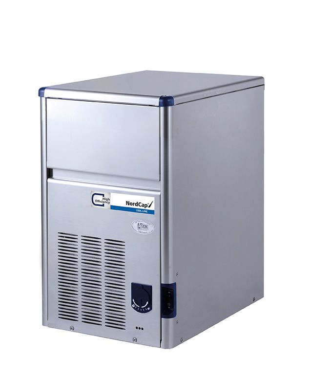
Bedienungsanweisung COOL-LINE-Eiswürfelbereiter SDE 18 L - Art. 41320201060
←
→
Transkription von Seiteninhalten
Wenn Ihr Browser die Seite nicht korrekt rendert, bitte, lesen Sie den Inhalt der Seite unten
Bedienungsanweisung
COOL-LINE-Eiswürfelbereiter SDE 18 L
[Art. 41320201060]

                     2020-02
SDE 18
R 134a
Kegeleisbereiter
Ice cubers
Machines á glaçons
Fabbricatori
di ghiaccio a cubetti
REV. 02/2020
2ANWEISUNGEN FÜR DIE Kontrollieren, daß der kleine Plastikvorhang
korrekt positioniert wurde und den Wasserauslauf
FUNKTION durch seine Lamellen verhindert
G. Der Prozess der Eisproduktion beginnt mit
INBETRIEBNAHME dem Wasser, das ständig auf die umgedrehten
Formen gespritzt wird und mit der ständig
Wenn das Gerät richtig installiert und an das abnehmenden Temperatur des Verdampfers.
Strom- und Wassernetz angeschlossen ist,
folgendermaßen vorgehen:
H. Wenn die Temperatur des Verdampfers
einen zuvor eingestellten Wert erreicht, schaltet
A. Die vordere Platte vom Eisbereiter das Thermostat seine Kontakte, beendet somit
abnehmen und den Schalter für den Spülvorgang den Gefrierzyklus und beginnt mit dem
ausfindig machen. Abtauzyklus.
B. Den Schalter für den Spülvorgang auf die
Position „IICLEAN” stellen. Dies schließt den I. Kontrollieren, daß während der Abtauphase
elektrischen Kreislauf des Wasser- das Versorgungswasser, das vorher für die
Eingangsventils und des Warmgasventils Herstellung benutzt wurde, aufgefüllt wird und
daß der Überschuß in den Überschußschlauch
und dann in den Abfluß des Gerätes geleitet
C. Nun stellt man sowohl den Schalter an der wird.
elektrischen Versorgungsleitung, als auch den
Hauptschalter des Gerätes auf die Position ON
(AN). Das Gerät beginnt mit der Abtauphase, J. Die Eiswürfel kontrollieren, die die richtigen
wobei folgende Komponenten in Funktion sind: Abmessungen haben müssen.
Ist dies nicht der Fall, wartet man auf den zweiten
EINGANGSVENTIL WASSER Zyklus der Eisproduktion, bevor man irgend eine
WARMGASVENTIL Einstellung vornimmt.
Es arbeiten auch die Pumpe und der Ventilator
(nur bei luftgekühlte Modelle)
K. Wenn notwendig, kann die Dauer des
Gefrierzyklus verändert werden, indem man das
D. Man läßt das Gerät etwa 3 - 4 Minuten lang Thermostats des Verdampfers auf der
in Abtauphase, bis man Wasser am Wasserabfluß Vorderseite des elektrischen Schaltbrettes leicht
hat. Danach bringt man den Schalter für den dreht (d.h. je 1/20 Drehung), bis man die optimale
Spülvorgang auf die Position „I ON” Abmessung erreicht hat.
Das Aussehen der produzierten Eiswürfel prüfen:
Würfel, die die richtige Abmessung haben, aber
ANMERKUNG. Während der Abtauphase besonders matt erscheinen, weisen auf
tritt Wasser durch das Solenoidventil, das für Wassermangel des Eisbereiters während der
den oberen Teil des Verdampfers bestimmt Endphase des Gefrierzyklus hin, oder darauf,
ist. Wenn das Wasser die ganze daß das Wasser, das für die Produktion benutzt
Plastikoberfläche des Verdampfers bedeckt wurde, von schlechter Qualität ist und
hat, wird das Wasser durch die angemessene Filter zur Reinigung einzusetzen
Wasserabführschlitze in die Sammelwanne sind.
abgelassen.
L. Während des Abtauzyklus bedeckt man
E. Das Gerät beginnt so seinen ersten die empfindliche Thermostatkugel mit einigen
Gefrierzyklus, wobei folgende Komponenten in Eiswürfeln und kontrolliert das Abschalten des
Funktion sind: Gerätes nach etwa 2 bis 3 Minuten.
KOMPRESSOR Man nimmt die Eiswürfel wieder von der
PUMPE empfindlichen Thermostatkugel und kontrolliert
VENTILATOR (nur bei luftgekühlte Modelle) das Anschalten des Gerätes nach etwa drei oder
vier Minuten.
F. Durch die Öffnung der Würfelabgabe
kontrollieren, daß der Spritzbalken richtig M. Die Platten wieder montieren und den
positioniert ist und daß das Wasser gleichmäßig Besitzer über die Funktion des Eisbereiters und
auf die umgedrehten Formen des Verdampfers die Art der Säuberung und Sterilisierung des
gespritzt wird. Geräts informieren.
3FUNKTIONSPRINZIP ABTAUZYKLUS ODER ABTAUUNG
Wenn das Thermostat des Verdampfers die
entsprechende Temperatur mißt, die bei voll
hergestellten Eiswürfeln erreicht wird, wechseln
In den Eiswürfelbereitern wird das zur Produktion die Kontakte des Thermostats ihre Position und
benutzte Wasser ständig von einer elektrischen versorgen folgende Bauteile:
Pumpe in Bewegung gehalten, die durch ein KOMPRESSOR
Spritzsystem das Wasser bei niedrigem Druck
zu den umgedrehten Formen des Verdampfers WASSEREINGANGSVENTIL
bringt. WARMGASVENTIL
In den Formen gefriert ein Teil des Wassers Das Wasser am Eintritt geht durch das Solenoid-
sofort; das restliche Wasser fällt in die darunter Eingangsventil und die Flußkontrolle, die sich im
angebrachte Rückgewinnungswanne und kann Innern desselben befindet, erreicht den oberen
wieder in den Kreislauf eintreten. Teil des Verdampfers, wo es durch die
Ablaufschlitze in die darunter liegende
Sammelwanne der Pumpe fließt.
GEFRIERZYKLUS Der Maximalstand des Wassers im Tank wird
Das gasförmige Kühlmittel wird vom Kompressor von einem Überstandsschlauch begrenzt,
bei hoher Temperatur gepumpt und durch den welcher die Aufgabe hat, das überflüssige
Kondensator in flüssiges Kühlmittel verwandelt. Wasser in den Abfluß zu leiten.
Die Leitung der Flüssigkeit erlaubt dem Kühlmittel, Das Kühlmittel in Gaszustand, das vom
vom Kondensator zum Kapillarrohr durch den Kompressor gepumpt wird, wird nun vom offenen
Entfeuchterfilter zu fließen. Während des Warmgasventil direkt zur Serpentine des
Durchflusses durch das Kapillarrohr verliert das Verdampfers geleitet und nicht durch den
flüssige Kühlmittel teilweise seinen Druck und Kondensator.
dadurch auch teilweise seine Temperatur. Das warme Gas, das im Innern der Serpentine
Danach erreicht es die Serpentinen des des Verdampfers zirkuliert, erhöht nun die
Verdampfers. Temperatur der Formen, wodurch sich die
Das auf die umgedrehten Formen gespritzte Eiswürfel ablösen.
Wasser des Verdampfers gibt Wärme an das Die gelösten Eiswürfel fallen auf ein schräges
zirkulierende Kühlmittel im Innern der Serpentinen Gitter, rutschen von dort durch eine Öffnung mit
ab, verursacht somit die Verdampfung und den einem Lamellenvorhang und fallen in den
Übergang vom flüssigen in den gasförmigen Eisbehälter.
Zustand. Das Kühlmittel im Dampfzustand wird Dank des Warmgasflusses in der Serpentine
wieder vom Kompressor durch die Ansaugleitung des Verdampfers steigt die Temperatur
angesaugt, nachdem es durch den Akkumulator desselben an und damit auch die Temperatur
geflossen ist. der empfindlichen Thermostatkugel des
Der Gefrierzyklus wird von einer Temperatur- Verdampfers, der seine Kontakte ändert, indem
kontrolle (Thermostat Verdampfer) reguliert, die die Spule des Warmgasventils und des
die Dauer des Zyklus und dadurch auch die Wassereingangsventils deaktiviert und die
Abmessung der Würfel bestimmt. Wasserkreislaufpumpe und der Ventilator
Die Komponenten, die während des Gefrierzyklus aktiviert wird und somit der neuen Gefrierzyklus
funktionieren, sind: beginnt.
DER KOMPRESSOR
DIE PUMPE BESCHREIBUNG DER KOMPONENTEN
DER VENTILATOR (bei luftgekühlten Modelle)
Bei den Ausführungen, die mit Luft gekühlt A. PUMPE
werden, fällt der Druck im Zulauf des Kühlsystems Die Pumpe arbeitet nur ständig während des
(Hochdruck) nach und nach von einem Wert von Gefrierzyklus, und führt das Wasser zur
10,5 bar (bei einer Raumtemperatur von 21 °C), Spritzplatte.
den man bei Beginn des Gefrierzyklus Von der Spritzbalken wird das Wasser durch die
aufzeichnet, bis zu einem Mindestwert von 6 bar Spritzer auf die umgedrehten Formen gebracht.
am Ende des Gefrierzyklus ab. In dieser Phase wird das Wasser entsprechend
Diese Werte erhöhen sich proportional mit der belüftet und dadurch können kristallklare und
Raumtemperatur, bei der das Gerät installiert ist. feste Eiswürfel produziert werden.
Bei Geräten, die unter normalen Bedingungen Es wird empfohlen, den Zustand der Lager
installiert sind (21°C Raumtemperatur), sinkt der mindestens alle 6 Monate zu kontrollieren.
Ansaugdruck oder der niedrige Druck schnell auf
1 bar bei Beginn des Gefrierzyklus ab, d.h. wenn
der Eiswürfel beginnt, sich zu bilden, indem sich B. SOLENOIDVENTIL WASSEREINGANG -
der Druck langsam auf 0 (0.1 bar senkt, wenn der ANSCHLUSS 3/4 ZOLL GAS GEWINDEZAPFEN
Eiswürfel voll hergestellt ist. Das Solenoidventil des Wassereinganges auf
Bei den wassergekühlten Modelle wird ein der Hinterseite des Gerätes wird nur während
Pressostat verwendet, der, in intermittierender der Abtauphase erregt.
Weise ein Solenoid ventil (auf der Wenn das Ventil erregt ist, kann eine begrenzte
Wasserversorgung am Kondensator) elektrisch Wassermenge in den oberen Teil des
aktiviert. Verdampfers fließen, um das Warmgas beim
4Ablösen der Eiswürfel aus den Formen zu F. VENTILATOR
unterstützen. Dieses Wasser wird dann von der
Platte des Verdampfers durch die Ablaufschlitze Der Ventilator, der mit dem Stromkreis durch die
in die darunter liegende Sammelwanne geleitet, Kontakte 3-4 des Verdampferthermostats
wo es von der Pumpe angesaugt und zum verbunden ist, arbeitet nur während des
Spritzbalken geleitet wird. Gefrierzyklus, indem er die Luft durch den
Kondensator zirulieren läßt und so den hohen
Druck innerhalb der zuvor eingestellten Werte
C. SOLENOIDVENTIL DES WARMGASES hält.
Das Solenoidventil des Warmgases besteht aus
zwei Teilen: dem Körper und der Spule. Auf G. HERMETISCHER KOMPRESSOR
Zulaufleitung des Kompressors angeordnet wird
das Ventil während des Abtauzyklus von den Der hermetische Kompressor hat die Aufgabe,
Kontakten 2-3 (zweite Position) und dem die Kühlflüssigkeit im ganzen System zirkulieren
Thermostat des Verdampfers aktiviert. zu lassen.
Während des Abtauzyklus wird die Spule, die Er saugt das Kühlmittel als Dampf mit niedriger
sich am oberen Teil des Warmgasventils befindet, Temperatur auf, drückt es zusammen und erhöht
aktiviert und zieht den Stift im Innern des so sowohl die Temperatur, als auch den Druck
Ventilkörpers an. und wandelt es somit in Dampf mit hohem Druck
Dieser Stift öffnet den Durchgang für das vom und Temperatur um, der den Kompressor durch
Kompressor gepumpte Warmgas und gestattet das Ablaufventil verläßt
so den direkten Fluß in die Serpentine des
Verdampfers. Auf diese Weise werden die
Eiswürfel aus den Formen gelöst. H. SPRITZBALKEN
Das von der Pumpe im Innern des Spritzbalkens
D. THERMOSTAT DES BEHÄLTERS geförderte Wasser fließt aus den Spritzern heraus,
die die Aufgabe haben, den Wasserstrahl in die
Das empfindliche Rohr des Behälterthermostats vom Verdampfer abgekühlten Formen zu richten.
(Kapillarrohr) ist im Schlauch eingesetzt und an
der Wand der Ablagekabine für das Eis befestigt.
Es hat die Aufgabe, die Funktion des Gerätes zu I. SICHERHEITSTHERMOSTAT
unterbrechen, wenn der empfindliche Schlauch Es befindet sich an der unteren Seite des
mit Eis bedeckt ist. Das Gerät wird wieder Schaltkastens (manuelle Einschiebung) und hält
angestellt, wenn das Eis entfernt wird. Das das Gerät an, wenn das Thermostat (an der
Behälterthermostat wurde werkseitig so reguliert, Flüssigkeitsleitung kurz vor dem Filter des
daß das Gerät bei 1 °C abgestellt und bei 4 °C Entfeuchters angebracht), eine Temperatur von
wieder angestellt wird.
80°C erreicht.
E. VERDAMPFERTHERMOSTAT
(KONTROLLE DER DIMENSIONEN J. SPÜLSCHALTER
DER WÜRFEL) Ein manueller Schalter, der sich im Schaltkasten
Das Verdampferthermostat auf der Vorderseite befindet und die Spule des Warmgasventils und
des elektrischen Schaltkastens wird in erster des Wassereingangsventils für die manuelle
Linie für die Temperaturkontrolle benutzt, die Wasserzufuhr erregt und um die Leitungen des
Ihre Kontakte 3-2 schließt, wenn die Temperatur Gerätes während der Säuberung zu reinigen.
sinkt (Ende des Gefrierzyklus) und sie öffnet,
indem die Kontakte 3-4 geschlossen werden,
wenn die Temperatur ansteigt (Ende Abtauzyklus). K. HOCHDRUCKPRESSOSTAT
Diese Kontrolle bestimmt die Dauer des (WASSERGEKÜHLTE VERSION)
Gefrierzyklus und damit die Größe der Eiswürfel. Diese Steuerung wird nur in wassergekühlten
Eine zu niedrige Einstellung produziert zu große Versionen verwendet. Sie sorgt dafür, daß der
Eiswürfel, während eine zu hohe Einstellung zu Druck des Kühlmittelsystems gehalten oder
kleine Eiswürfel herstellt. Die Kontakte des gesenkt wird, indem sie die Spule des
Verdampferthermostats auf der zweiten Position
(Kontakte 2-3) schließen den elektrischen Wassereinlaß - Magnetventils, das intermittierend
Kreislauf an den Komponenten des Abatuzyklus den Fluß des Kühlwassers zum Kondenser
und kontrollieren dessen Dauer. steuert, aktiviert.
Das Verdampferthermostat wurde werkseitig
bei Raumtemperatur voreingestellt. L. WASSEREINGANGS-SOLENOIDVENTIL
.m
.n Bei den mit Wasser gekühlten Versionen ist ein
zweites Solenoidventil für den Wassereingang
des Kondensators vorgesehen, das von einem
ANMERKUNG. Das Thermostat dient automatischen Hochdruckwächter überwacht
zur Regulierung der Würfelgröße wird. Wenn diese versorgt wird, erlaubt sie einen
bei sich änderder Raum oder ausgeglichenen Wasserfluß in die Kühlserpentine
Wassertemperatur. des Kondensators zu gelangen, damit die
Eine Einstellung in kleine Schritten Temperatur und der Druck des, sich im Kreislauf
von 1/20 Drehung wird empfohlen. befindlichen, Kühlmittels erniedrigt wird.
5ANWEISUNGEN FÜR DIE 8. Das Gerät etwa 20 Minuten laufen lassen.
REINIGUNG DES ANMERKUNG. Die Menge des Entkalkungs-
mittels, wie auch die benötigte Zeit für die
WASSERKREISLAUFES Entkalkung hängen von dem Zustand des
Wasserkreislaufes ab (Ablagerungen)
1. Die vordere und obere Wandtafel 9. Das Gerät abschalten, die Entkalkungs-
abnehmen, um Zugriff zum Schaltkasten und lösung ablassen und in den oberen Teil des
zum Verdampfer zu haben. Verdampfers 2 oder 3 Liter Trinkwasser schütten,
um sowohl die Formen, als auch die Plastikplatte
2. Das Ende des Abtauzyklus abwarten und zu spülen.
das Gerät dann durch den Hauptschalter
abschalten. 10. Das Gerät anschalten. Die Pumpe beginnt
zu arbeiten, um das Wasser neu zirkulieren zu
3. In einem sauberen Eimer die Lösung für lassen und das Innere der hydraulischen Anlage
die Entkalkung vorbereiten, indem man 1 - 2 zu spülen.
Liter warmes Wasser (45-50 °C) mit 0,2 Liter
Entkalkungsmittel vermischt. 11. Die Punkte 8 und 9 mindestens 2 Mal
wiederholen.
ACHTUNG. Entkalkungsmittel für 12. Auf den oberen Teil des Verdampfers eine
Eisbereiter enthalten eine Lösung aus Karaffe Wasser mit Desinfektionsmittel gießen
Phosphorsäure und essigsaurem und das Gerät wieder anschalten, damit der
Hydroxid. Diese Lösung ist ätzend und ganze hydraulische Kreislauf etwa 10 Minuten
kann, wenn eingenommen, Magen- lang desinfiziert wird.
beschwerden hervorrufen. In diesem Fall
muß eine große Menge Wasser oder Milch
getrunken und sofort ein Arzt gerufen ACHTUNG. das Desinfektionsmittel nicht
werden. Bei Hautkontakt ist es mit dem Entkalkungsmittel mischen,
ausreichend, mit viel Wasser zu spülen. damit keine aggressiven Säuren
VOR KINDERN FERN HALTEN. entstehen können.
13. Das Desinfektionsmittel aus dem Tank
4. Das ganze Eis aus dem Behälter nehmen, laufen lassen, den Wasserhahn öffnen und das
damit es nicht mit der Entkalkungslösung in Gerät einschalten.
Kontakt kommt.
14. Wenn man am Ablauf das Austreten von
5. Entfernen Sie den am Boden des Sumpfs / Wasser bemerkt, schaltet man den Spülschalter
der Gefrierkammer befindlichen Kunststoff- auf ION, um das Gerät wieder normal arbeiten zu
becher, um alles Wasser und Ablagerungen lassen.
ablaufen zu lassen.
15. Den Deckel des Verdampfers und die
Wandtafeln montieren.
16. Kontrollieren, daß die Eiswürfel nach dem
ersten Gefrierzyklus durchsichtig sind und keinen
Säuregeschmack haben.
ACHTUNG. Keine matten - weißen Würfel
mit Säuregeschmack benutzen, die nach
der Desinfektion und Entkalkung des
hydraulischen Systems produziert
werden könnten.
Auf jeden Fall ist es am besten, wenn man
lauwarmes Wasser in den Behälter
schüttet, um die ersten produzierten
Eiswürfel aufzulösen.
6. Den Deckel des Verdampfers abnehmen 17. Die Innenwände des Eisbehälters abspülen.
und langsam die Entkalkungslösung zwischen
die Kupferformen laufen lassen. Einen Pinsel ANMERKUNG. Es wird daran erinnert, daß
benutzen, um die Verkalkung in den die Innenwände des Behälters zur Vermei-
unzugänglicheren Ecken zu entfernen. dung von Bakterienbildungen jede Woche
mit einer Mischung aus Wasser und
7. Den Spülschalter auf „IICLEAN” stellen, Desinfektionsmittel desinfiziert werden
den Wasserhahn schließen und das Gerät mit sollten.
dem Hauptschalter anstellen.
6OPERATING INSTRUCTIONS
START UP G. The ice making process takes place
thereby, with the water sprayed on the inverted
After having correctly installed the ice maker and molds that gets gradually refrigerated by the
completed the plumbing and electrical heat exchanged with the refrigerant flowing into
connections, perform the following “Start-up” the evaporator serpentine.
procedure.
A. Remove the unit front panel and locate H. When the evaporator temperature reaches
the cleaning switch on the control box. a preset value the evaporator thermostat or cube
size control changes its contacts; the freezing
cycle ends and starts the defrost or harvest
B. Set the cleaning switch in the cleaning cycle.
position. This will close the electrical circuit to the
water inlet valve and to the hot gas valve
I. Check, during the first defrost/harvest
cycle, that the incoming water flows correctly
C. Switch ON the power line disconnect into the sump reservoir in order to re-fill it and the
switch. Unit will start up in defrost cycle mode. surplus overflows through the overflow drain
During this cycle the components energized are: tube.
WATER INLET SOLENOID VALVE
HOT GAS SOLENOID VALVE
J. Check the texture, the right weight and
The Water pump and the Fan motor are also in dimension of ice cubes just released.
operation. If not, wait for the second defrost/harvest cycle
before performing any adjustment.
D. Let unit stay in defrost cycle for about
three/four minutes till water is coming out from
the drain hose, then move the cleaning switch to K. If required, the length of the freezing cycle
the operation position. can be modified by turning with very little
movements (6 degree or 1 minute each time) the
NOTE. During the defrost cycle, the water knob of the cube size control evaporator
inlet solenoid valve is energized. The water thermostat located in front of the control box until
flows through the valve to the back side of the desired size is achieved.
the evaporator platen and then down to fill up If the ice cubes are shallow and cloudy, it is
possible that the ice maker runs short of water
the icemaker sump tank for the next freezing during the end of the freezing cycle or, the quality
cycle. of the supplied water requires the use of an
appropriate water filter or conditioner.
L. During the defrost or harvest cycle hold a
OPERATIONAL CHECKS handful of ice cubes against the bulb of the
storage bin thermostat; the icemaker switch OFF
E. The unit now starts its first freezing cycle in about one-two minutes.
with the following components in operation: Take out the ice from the storage bin thermostat.
The ice maker should restart automatically in
COMPRESSOR three-four minutes.
WATER PUMP
FAN MOTOR in air cooled version NOTE. The bin thermostat is factory set at
1°C OUT and 4°C IN.
F. Check to see through the ice discharge
opening that the spray system is correctly seated
and that the water jets uniformely reach the M. Re-fit the unit front panel then instruct the
inverted molds; also make sure that the plastic owner/user on the general operation of the ice
curtain is hanging freely and there is not excessive machine and about the cleaning and care it
water spilling through it. requires.
7PRINCIPLE OF OPERATION
How it works The above values are in relation as well to the
In the ice makers the water used to make the ice ambient temperature of the ice maker site and
is kept constantly in circulation by a water pump they are subject to rise with the increase of this
which primes it to the spray system nozzles from temperature.
where it is diverted on the inverted molds of the At the start of the freezing cycle the refrigerant
suction or lo-pressure lowers rapidly to 1.0 bar
evaporator (Fig. A). then it declines gradually - in relation
A small quantity of the sprayed water freezes into with the growing of the ice thickness - to reach,
ice; the rest of it cascades by gravity into the at the end of the cycle, approx. 0 ÷ 0.1 bar
sump assembly below for recirculation. with the cubes fully formed on the molds.
On the models water cooled version the hi-
pressure controls is used to intermittently
energize a water solenoid valve located on the
FREEZING CYCLE (Fig. B) water supply line to the condenser.
The hot gas refrigerant discharged out from the
compressor reaches the condenser where, being
cooled down, condenses into liquid. Flowing into DEFROST OR HARVEST CYCLE (Fig. D)
the liquid line it passes through the drier/filter, When the temperature of the evaporator
then it goes all the way through the capillary tube thermostat, in contact with the evaporator
where it looses its pressure. serpentine, drops to a pre-set value it changes
Next the refrigerant enters into the evaporator its electrical contacts energizing the following
serpentine (which has a larger diameter then the components:
capillary tube) and starts to boil off; this reaction
is emphasized by the heat transferred by the COMPRESSOR
sprayed water. WATER INLET SOLENOID VALVE
The refrigerant then increases in volume and HOT GAS SOLENOID VALVE
changes entirely into vapor.
The vapor refrigerant then passes through the The incoming water, passing through the water
suction accumulator (used to prevent that any inlet valve and the flow control, runs over the
small amount of liquid refrigerant may reach the evaporator platen and then flows by gravity
compressor) and through the suction line. In through the interstices down into the sump/
reservoir (Fig. C).
both the accumulator and the suction line it The water filling the sump/reservoir forces part
exchanges heat with the refrigerant flowing into of the surplus water from the previous freezing
the capillary tube (warmer), before to be sucked cycle to go out to the waste through the overflow
in the compressor and to be recirculated as hot pipe. This overflow limits the level of the sump
compressed refrigerant gas. water which will be used to produce the next
The freezing cycle is controlled by the evaporator batch of ice cubes.
thermostat which has its bulb in contact with the Meanwhile the refrigerant, as hot gas discharged
evaporator serpentine. from the compressor, flows through the hot gas
The electrical components in operation during valve directly into the evaporator serpentine by-
the freezing cycle are: passing the condenser.
The hot gas circulating into the serpentine of the
COMPRESSOR evaporator warms up the copper molds causing
WATER PUMP the harvest of the ice cubes. The ice cubes,
released from the inveted molds, drop by gravity
FAN MOTOR (in air cooled version) onto a slanted cube chute, then through a
The refrigerant head pressure is gradually curtained opening they fall into the storage bin.
reduced from a value of approx. 10,5 bars at the When the temperature of the evaporator
beginning of the freezing cycle with the unit at thermostat bulb reaches the value of +3 ÷4°C
their electrical contacts move back to the previous
21°C ambient temperature, to a minimun value position activating a new freezing cycle and
of approx. 6 bars just at the end of the freezing deenergizing both the hot gas and the water inlet
cycle few seconds before the starting of the valves (closed).
defrost cycle.
The declining of the pressure is relied to the
reduction of the evaporating pressure, caused NOTE. The length of the defrost/harvest
by the progressive growth of the ice thickness on cycle (not adjustable) changes according
to the ambient temperature (shorter for hi
the inverted molds and to the flow of air drown ambient temperature and longer for low
through the air cooled condenser by the fan one).
motor.
8COMPONENTS DESCRIPTION The cube size control is set up in the factory
to ensure the correct dimension.
.
A. WATER PUMP .
The water pump operates continually throughout
the freezing cycle.
The pump primes the water from the sump to the NOTE. The thermostat is very sensitive!
spray system and through the spray nozzles By a little movement of the knob correspond
sprays it into the inverted cup molds to be frozen a big size change of the ice cubes. If
into crystal clear ice cubes. necessary only, it's recommended to make
It is recommended that the pump motor bearings max 1/20 of turn regulation each time.
be checked at least every six months.
F. FAN MOTOR
B. WATER INLET SOLENOID VALVE - The fan motor is electrically connected in parallel
3/4 MALE FITTING to the water pump and it operates continuously
The water inlet solenoid valve is energized only only during the freezing cycle keeping the proper
during the defrost cycle. head pressure by circulating air through the
When energized it allows a metered amount of condenser fins.
incoming water to flow over the evaporator cavity
to assist the hot gas in defrosting the ice cubes.
The water running over the evaporator cavity G. COMPRESSOR
drops by gravity, through the dribbler interstices The hermetic compressor is the heart of the
of the platen, into the sump reservoir. refrigerant system and it is used to circulate and
retrieve the refrigerant throughout the entire
system. It compresses the low pressure
C. HOT GAS SOLENOID VALVE refrigerant vapor causing its temperature to rise
The hot gas solenoid valve consists basically in and become high pressure hot vapor (hot gas)
two parts: the valve body and the valve coil. which is then released through the discharge valve.
Located on the hot gas line, this valve is energized
by the contacts 3-2 of the evaporator thermostat
during the defrost cycle. H. WATER SPRAY SYSTEM
During the defrost cycle the hot gas valve coil is Through its nozzles it sprays the water on each
activated so to attract the hot gas valve piston in individual inverted mold to be frozen into ice.
order to give way to the hot gas discharged from
compressor to flow directly into the evaporator
serpentine to defrost the formed ice cubes. I SAFETY HI TEMPERATURE THERMOSTAT
Located on the bottom part of the control box it is
a manual reset switch that trips OFF the operation
D. BIN THERMOSTAT of the machine when its bulb (located on the
The bin thermostat control body is located in the liquid line just before the drier) reaches the
front of control box behind the front louvered panel. temperature of 80°C.
The thermostat sensing tube is located into a
bulb holder on the side wall of the ice storage bin
where it automatically shuts the icemaker OFF J. CLEANING SWITCH
when in contact with the ice and re-starts the
icemaker when the ice is removed. Factory Located on the bottom left side of the control box
settings are 1°C OUT and 4°C IN. is used to energize the water inlet and the hot gas
valves so to charge the water into the sump tank
of the machine.
E. CUBE SIZE CONTROL (EVAPORATOR
THERMOSTAT)
The cube size control (evaporator thermostat) K. HI PRESSURE CONTROL
body is located in the front of control box behind Used on water cooled ice makers it functions to
the front louvered panel; it’s basically a reverse maintain the head pressure within the preset
acting temperature control which closes the values of 7,5 ÷10,5 bars, by intermittently activating
contacts 3-2 when its temperature decreases the water inlet valve to the condenser.
and closes the opposite contacts 3-4 when the
temperature rises.
The thermostat sensing bulb is located into a
plastic tube (bulb holder) secured by two clips L. WATER INLET SOLENOID VALVE -
directly to the evaporator serpentine. 3/4 MALE FITTING
This control determines the length of the freezing A second water inlet solenoid valve, operating
cycle and correspondingly the size of the cubes. through an automatic hi-pressure control, is used
A lower setting will produce a larger cube on water cooled versions to supply water to the
(oversize) while a higher setting a smaller cuber condenser.
(shallow size). When activated it supplies a metered amount of
When closed on contacts 3-2 it activates the water to the condenser in order to limit its tempe-
defrost or harvest cycle components. rature and the refrigerant operating high rpessure.
9MAINTENANCE AND CLEANING INSTRUCTIONS
CLEANING INSTRUCTIONS OF WATER
SYSTEM NOTE. The amount Cleaner and the time
needed for the cleaning of water system
1. Remove the front and top panels to gain depends of the water conditions.
access either to the control box and to the
evaporator. 9. Switch OFF then flush out the cleaning
solution from the sump reservoir then pour onto
2. Make sure that all ice cubes have been the evaporator cavity two or three liters of clean
released from their molds, then switch off the potable water to rinse the molds and the platen.
unit.
10. Switch ON the machine. The water pump is
3. Prepare the cleaning solution by diluting in
a plastic container one or two liters of warm water again in operation to circulate the water in order
(45°-50°C) with a 0,1-0,2 liters of Ice Machine to rinse the entire water system.
Cleaner.
11. Do the operation as per steps 8 and 9 twice
WARNING. The Ice Machine Cleaner so to be sure no more traces of descaling solution
contains Phosphoric and Hydroxyacetic remains into the sump.
acids.
These compounds are corrosive and may 12. Pour on the upper side of the evaporator
cause burns if swallowed, DO NOT indu- platen fresh water with a capfull of disinfectant
ce vomiting. Give large amounts of water solution then turn again the machine in normal
or milk. Call Physician immediately. operating mode so to sanitize all the water system
In case of external contact flush with for approx. 10 minutes.
water. KEEP OUT OF THE REACH OF
CHILDREN.
NOTE. Do not mix descaling with disinfectant
4. Scoop out all the ice cubes stored into the solution to avoid the generation of a very
bin in order to prevent them from being aggressive acid.
contaminated with the cleaning solution then
flush out the water from the sump reservoir by 13. Flush out the disinfectant solution from the
removing the overflow stand-pipe. sump reservoir, open the water tap then switch
on the machine.
5. Remove the plastic cup located on the
bottom of sump/freezing chamber to drain out all 14. When water starts overflowing through
water and scale deposits. the drain line, set the switch to "operation"
position "I-ON". The unit is now ready to resume
normal operation.
15. Place again the evaporator cover and the
unit service panels.
16. At completion of the freezing and harvest
cycle make sure of proper texture and clearness
of the ice cubes and that, they do not have any
acid taste.
ATTENTION. In case the ice cubes are
cloudy-white and have an acid taste, melt
them immediately by pouring on them
some warm water. This to prevent that
somebody could use them.
6. Remove the evaporator cover then slowly
pour onto the evaporator platen the cleaning
solution. With the help of a brush dissolve the 17. Wipe clean and rinse the inner surfaces of
most resistant and remote scale deposits in the the storage bin.
platen.
7. Turn the CLEANING switch on "II-CLEAN", REMEMBER. To prevent the accumulation
close the water tap and switch on the machine. of undesirable bacteria it is necessary to
sanitize the interior of the storage bin with an
8. Allow the ice maker to operate for about 20 anti-algae disinfectant solution every week.
minutes.
10ISTRUZIONI DI Verificare che la tendina di plastica sia posizio-
nata correttamente impedendo la fuoriuscita
FUNZIONAMENTO dell’acqua attraverso le proprie lamelle.
AVVIAMENTO G. Il processo di fabbricazione del ghiaccio ha
così inizio con l’acqua che viene continuamente
Dopo aver correttamente installato l'apparec- spruzzata sugli stampini rovesciati e con la tem-
chio ed averlo collegato alla rete elettrica ed peratura dell’evaporatore che gradualmente si
idraulica, seguire la seguente procedura per abbassa.
l'avviamento.
A. Togliere dal fabbricatore di ghiaccio il pan nel- H. Quando la temperatura dell'evaporatore
lo frontale e localizzare l'interruttore di lavaggio. raggiunge un valore predeterminato il termosta-
to evaporatore commuta i suoi contatti dando
luogo alla fine del ciclo di congelamento ed
B. Spostare l'interruttore di lavaggio sulla po- all'inizio del ciclo di scongelamento.
sizione "II CLEAN". Questo chiude il circuito
elettrico della valvola di ingresso dell'acqua e
della valvola gas caldo.
I. Verificare che durante la fase di
scongelamento l’acqua di alimentazione vada a
C. Spostare, a questo punto sia l'interruttore reintegrare quella precedentemente usata per la
posto sulla linea di alimentazione elettrica che produzione dei cubetti e che quella eccedente
l'interruttore generale dell'apparecchio sulla po- trabocchi nel tubo di troppo pieno e fluisca nella
sizione ON (acceso). L'apparecchio partirà nella tubazione di scarico dell’apparecchio.
fase di sbrinamento con i seguenti componenti in
funzione:
VALVOLA INGRESSO ACQUA J. Osservare i cubetti di ghiaccio prodotti.
VALVOLA GAS CALDO Questi devono essere della giusta dimensione.
Nel caso contrario, attendere il secondo ciclo di
Sono in funzione anche la Pompa ed il
Motoventilatore (nel caso di apparecchi raffred- produzione del ghiaccio, prima di effettuare qual-
dati ad aria). siasi regolazione.
D. Lasciare funzionare la macchina nella fase K. Se necessario la durata del ciclo di
di sbrinamento per circa tre - quattro minuti fino congelamento può essere modificata ruotando
ad avere dell'acqua allo scarico dell'apparec- con piccolissimi spostamenti (spostare di 1/20 di
chio. Quindi spostare l'interruttore di lavaggio giro per volta) la manopola del termostato
sulla posizione "I ON". evaporatore posta nella parte frontale della sca-
tola elettrica fino al raggiungimento della dimen-
sione ottimale.
NOTA. Durante la fase di sbrinamento l'ac- Controllare l'aspetto dei cubetti di ghiaccio pro-
qua entra nell'apparecchio, attraverso la val- dotti: cubetti aventi delle corrette dimensioni
vola solenoide di ingresso dell'acqua, eccita- esterne ma particolarmente opachi, indicano
ta durante questa parte del ciclo, e attraverso che il fabbricatore di ghiaccio ha avuto una
l'apposita tubazione è indirizzata sulla parte mancanza d'acqua durante la fase finale del
superiore dell'evaporatore. Dopo aver co- ciclo di congelamento o che, l'acqua usata per la
perto l'intera superficie di plastica produzione del ghiaccio è di pessima qualità e
dell'evaporatore, l'acqua viene scaricata, at-
traverso le fessure di drenaggio, nella quindi si rende necessario l'uso di filtri adeguati
vaschetta di raccolta, riempiendola. o di un condizionatore d'acqua.
L. Durante il ciclo di sbrinamento, coprire con
E. L'apparecchio inizia così il suo primo ciclo una manciata di cubetti il bulbo sensibile del
di congelamento con i seguenti componenti in termostato contenitore e verificare lo spegni-
funzione: mento dell'apparecchio dopo circa due o tre
COMPRESSORE minuti.
POMPA Togliere la manciata di cubetti dal bulbo sensibi-
le e controllare che l'apparecchio si rimetta in
MOTOVENTILATORE (solo nei modelli raffred- moto in circa tre o quattro minuti.
dati ad aria)
F. Osservare attraverso l’apertura di scarico M. Rimontare i pannelli precedentemente ri-
dei cubetti che la barra spruzzante sia corretta- mossi quindi istruire il proprietario sul funziona-
mente posizionata e che l’acqua venga unifor- mento del fabbricatore di ghiaccio così come
memente spruzzata sugli stampini rovesciati sulle operazioni di pulizia ed igienizzazione del
dell’evaporatore. medesimo.
11PRINCIPIO DI CICLO DI SCONGELAMENTO O
SBRINAMENTO
FUNZIONAMENTO
Al momento in cui il termostato evaporatore
Nei fabbricatori di ghiaccio l’acqua usata per la sente la temperatura corrispondente ai cubetti di
produzione del ghiaccio è tenuta costantemente ghiaccio di dimensione piena, i contatti dello
in movimento da una pompa elettrica che attra- stesso cambiano posizione alimentando i se-
verso un sistema spruzzante dirige l’acqua a guenti componenti:
pressione moderata sugli stampini rovesciati COMPRESSORE
dell’evaporatore. Qui una parte dell’acqua spruz- VALVOLA DI INGRESSO ACQUA
zata ghiaccia all’istante; il rimanente di essa
ricade nel sottostante serbatoio di recupero per VALVOLA DEL GAS CALDO
essere ricircolata. L’acqua in immissione passa attraverso la valvo-
la solenoide di ingresso ed il controllo di flusso
che è posto all’interno della medesima, arriva
CICLO DI CONGELAMENTO sulla parte superiore dell’evaporatore da dove
Il refrigerante allo stato gassoso ed ad alta cola, attraverso le fessure di drenaggio, nel
temperatura viene pompato dal compressore e, sottostante serbatoio di pescaggio della pompa.
passando poi attraverso il condensatore, si tra- Il livello massimo dell’acqua nel serbatoio è limi-
sforma in refrigerante allo stato liquido. tato da un tubo di troppo pieno che ha la funzione
La linea del liquido permette al refrigerante di di indirizzare verso lo scarico l’acqua in eccesso.
fluire dal condensatore al tubo capillare attraver- Il refrigerante allo stato gassoso, pompato dal
so il filtro deumidificatore. Durante il passaggio compressore, viene ora dirottato dalla valvola del
attraverso il tubo capillare il refrigerante allo gas caldo aperta direttamente alla serpentina
stato liquido perde gradualmente parte della sua dell’evaporatore, seguendo il percorso più diret-
pressione e conseguentemente parte della sua to cioè, non passando attraverso il condensatore.
temperatura. Successivamente raggiunge ed Il gas caldo circolante all’interno della serpentina
entra nella serpentina dell’evaporatore. dell’evaporatore, fa aumentare la temperatura
L’acqua spruzzata sugli stampini rovesciati degli stampini causando quindi lo stacco dai
dell’evaporatore cede calore al refrigerante cir- medesimi dei cubetti di ghiaccio.
colante all’interno della serpentina, causandone I cubetti che si staccano cadono sopra una griglia
l’evaporazione, ed il conseguente cambiamento inclinata da dove scivolano attraverso l’apertura
del suo stato fisico, cioè da liquido diviene vapo- con tendina a lamelle, per cadere all’interno del
re. Il refrigerante allo stato vaporoso dopo esse- contenitore del ghiaccio.
re passato attraverso l’accumulatore viene aspi- Grazie al fluire del gas caldo nella serpentina
rato nuovamente nel compressore tramite la dell'evaporatore, la temperatura dello stesso sale
linea di aspirazione. e conseguentemente sale anche la temperatura
Il ciclo di congelamento è regolato da un control- del bulbo sensibile del termostato evaporatore il
lo della temperatura (termostato evaporatore) quale cambia i suoi contatti disattivando la bobi-
che determina la durata del ciclo e di conseguen- na della valvola gas caldo e della valvola di
za la dimensione dei cubetti. ingresso acqua ed attivando la pompa di circola-
I componenti in funzione durante il ciclo di zione dell'acqua e il ventilatore iniziando così un
congelamento sono: nuovo ciclo di congelamento.
IL COMPRESSORE
LA POMPA
DESCRIZIONE DEI COMPONENTI
IL VENTILATORE (nei modelli raffreddati ad aria)
Nei modelli raffreddati ad aria la pressione di A. POMPA
mandata del sistema refrigerante (alta pressio- La pompa opera in continuazione soltanto du-
ne) cala progressivamente da un valore di circa rante il ciclo di congelamento dirigendo l'acqua
10,5 bar (con temperatura ambiente di 21°C), che verso la piastra spruzzante.
si riscontra all’inizio del ciclo di congelamento, Dalla barra spruzzante l'acqua, attraverso gli
fino ad un valore minimo di 7 bar proprio alla spruzzatori viene diretta sugli stampini rovesciati
fine del ciclo di congelamento. Questi valori sono subendo, in questa fase, una certa aerazione
influenzati della temperatura dell’ambiente in cui permettendo così di ottenere un cubetto di ghiac-
è installato l’apparecchio e aumentano propor- cio solido e cristallino.
zionalmente con l’aumentare di quest’ultima. Si consiglia di controllare lo stato dei cuscinetti
Con apparecchi installati in condizioni normali almeno ogni sei mesi.
(21°C ambiente) la pressione di aspirazione o
bassa pressione scende rapidamente a 1 bar
all’inizio del ciclo di congelamento, cioè quando B. VALVOLA SOLENOIDE DI INGRESSO
il cubetto di ghiaccio inizia a formarsi, declinando DELL'ACQUA - RACCORDO DA 3/4
lentamente a circa a 0÷0.1 bar allorché il cubetto GAS MASCHIO
di ghiaccio è completamente formato. La valvola solenoide di ingresso dell'acqua posta
Nei modelli raffreddati ad acqua è utilizzato un nella parte posteriore dell'apparecchio, è eccita-
pressostato per alimentare elettricamente, in ta solamente durante il ciclo di sbrinamento.
modo intermittente, una valvola a solenoide si- Quando è eccitata permette, ad una limitata quan-
tuata sulla linea idraulica di alimentazione al tità d'acqua, di fluire verso la parte superiore della
condensatore. piastra evaporatore assistendo così il gas caldo
12durante la fase di distacco dei cubetti. Quest'acqua F. VENTILATORE
viene quindi scaricata dalla piastra dell'evaporatore, Il ventilatore, collegato al circuito elettrico attra-
attraverso le fessure di scarico, nel serbatoio di verso i contatti 3-4 del termostato evaporatore,
raccolta sottostante da dove viene aspirata dalla
opera soltanto durante il ciclo di congelamento,
pompa e diretta alla barra spruzzante.
facendo circolare l'aria attraverso il condensato-
re e mantenendo così, entro valori prestabiliti
C. VALVOLA SOLENOIDE DEL l'alta pressione.
GAS CALDO
La valvola solenoide del gas caldo è composta
essenzialmente da due parti, rispettivamente il G. COMPRESSORE ERMETICO
corpo e la bobina. Situata sulla linea di mandata Il compressore ermetico ha il compito di far circo-
del compressore è attivata dai contatti 3-2 (se- lare il refrigerante attraverso l'intero sistema.
conda posizione), del termostato evaporatore Esso aspira il refrigerante sotto forma di vapore
durante il ciclo di sbrinamento. a bassa pressione e temperatura, lo comprime,
Durante il ciclo di sbrinamento la bobina, colloca- facendone aumentare di conseguenza sia la
ta sulla parte superiore della valvola gas caldo è pressione che la temperatura, e lo trasforma in
attivata attraendo pertanto il pistoncino posto vapore ad alta pressione e temperatura che
all'interno del corpo valvola. lascia il compressore attraverso la valvola di
Questo apre il passaggio al gas caldo pompato scarico.
dal compressore, consentendogli di fluire diret-
tamente nella serpentina dell'evaporatore di-
staccando così i cubetti di ghiaccio dai bicchierini.
H. BARRA SPRUZZANTE
L'acqua, forzata dalla pompa all'interno della
D. TERMOSTATO CONTENITORE
barra spruzzante, fuoriesce attraverso gli spruz-
Il tubo sensibile del termostato contenitore (tubo zatori i quali hanno il compito di dirigere il getto
capillare) è inserito nel tubo portabulbo fissato dacqua verso gli stampini raffreddati dell'eva-
sulla parete della cabina di deposito del ghiaccio poratore.
ed ha il compito di interrompere il funzionamento
dell'apparecchio quando il tubo sensi bile è co-
perto dal ghiaccio e di farlo ripartire non appena il I. TERMOSTATO DI SICUREZZA
ghiaccio sia stato rimosso. Il termostato conteni-
tore è tarato direttamente in fabbrica per fermare Posto nella parte inferiore della scatola elettrica
l'apparecchio a 1°C e riattaccarlo a 4°C. è del tipo a reinserimento manuale ed arresta il
funzionamento dell'apparecchio quando il suo
bulbo (ancorato alla linea dal liquido poco prima
E. TERMOSTATO EVAPORATORE del filtro deumidificatore) raggiunge la tempera-
(CONTROLLO DELLA DIMENSIONE tura di 80°C.
DEI CUBETTI)
Il termostato evaporatore posto nella parte fron-
tale della scatola elettrica, è essenzialmente un J. INTERRUTTORE DI LAVAGGIO
controllo della temperatura che chiude i suoi Interruttore manuale, posto nella parte sinistra
contatti 3-2 quando la temperatura scende (fine della scatola elettrica eccita la bobina della val-
ciclo di congelamento) e li apre chiudendo i vola del gas caldo e della valvola di ingresso
contatti 3-4 quando la temperatura sale (fine dell'acqua per il caricamento manuale dell'acqua
ciclo di sbrinamento).
e per risciacquare il circuito idraulico dell'appa-
Questo controllo determina la durata del ciclo di
congelamento e di conseguenza la dimensione recchio durante le operazioni di pulizia.
dei cubetti di ghiaccio. Una bassa regolazione
produrrà cubetti di ghiaccio troppo grandi mentre K. VALVOLA SOLENOIDE DI INGRESSO
al contrario un'alta regolazione produrrà cubetti ACQUA
di ghiaccio (troppo piccoli). I contatti del termo- Una seconda valvola solenoide di ingresso ac-
stato evaporatore sulla seconda posizione (con- qua, comandata da un pressostato di alta auto-
tatti 3-2) chiudono il circuito elettrico ai compo-
nenti del ciclo di sbrinamento controllandone la matico, è prevista per alimentare il condensato-
sua durata. re. Quando è attivata permette ad un flusso
Il termostato evaporatore è regolato in fabbrica calibrato di acqua di entrare nella serpentina di
per garantire la corretta dimensione del cubetto. raffreddamento in modo da asportare il calore ed
. abbassare la temperatura nonchè la pressione
. del refrigerante in circolazione.
NOTA. Il termostato è molto sensibile. Ad un L. PRESSOSTATO DI ALTA
piccolo spostamento della maniglia di
regolazione corrisponde un grande cambia- Impiegato sia nei modelli raffreddati ad aria che
mento dimensionale del cubetto. Nel caso ad acqua mantiene entro valori prestabiliti la
sia strettamente necessario, si raccomanda pressione di mandata del circuito frigorifero ali-
di fare regolazione di 1/20 di giro per volta. mentando ad intermittenza la bobina della valvo-
la solenoide di ingresso acqua al condensatore.
13ISTRUZIONI PER LA PULIZIA 8. Lasciare l’apparecchio in funzione per circa
20 minuti.
DEL CIRCUITO IDRAULICO
NOTA. La quantità di disincrostante così
come il tempo necessario per la
1. Togliere il pannello frontale e superiore per disincrostazione dipendono dalle condizioni
accedere sia alla scatola elettrica che del circuito idraulico (incrostazioni).
all’evaporatore.
9. Spegnere l'apparecchio, scaricare la solu-
2. Attendere la fine del ciclo di sbrinamento zione disincrostante dal serbatoio quindi versare
quindi spegnere l'apparecchio tramite l'interrut- nella parte superiore dell'evaporatore 2 o 3 litri di
tore principale. acqua potabile per risciacquare sia gli stampini
che la piastra in plastica.
3. In un secchio pulito preparare la soluzione
disincrostante diluendo in 1-2 litri di acqua pota- 10. Accendere l'apparecchio. La pompa è di
bile calda (45-50°C) 0,2 litri di disincrostante. nuovo in funzionamento per ricircolare l'acqua
così da risciacquare l'intero circuito idraulico.
ATTENZIONE. I disincrostanti per pro-
duttori di ghiaccio contengono una solu- 11. Ripetere quanto esposto ai punti 8 e 9
zione di acido fosforico e idrossiacetico. almeno 2 volte.
Questa soluzione è corrosiva e, se ingeri-
ta, può causare disturbi intestinali. Non 12. Versare sulla parte superiore
provocare il vomito. In questo caso biso- dell'evaporatore una caraffa d'acqua contenente
gna bere una abbondante quantità di ac- della sostanza battericida, quindi rimettere in
qua o di latte e chiamare subito il medico. funzione l'apparecchio allo scopo di igienizzare
Nel caso di contatto esterno è sufficiente tutto il circuito idraulico per circa 10 minuti.
lavare la parte con acqua.
TENERLO LONTANO DALLA PORTATA ATTENZIONE. Non miscelare la sostanza
DEI BAMBINI. battericida con il disincrostante al fine di
evitare la generazione di acidi molto ag-
gressivi.
4. Prelevare tutto il ghiaccio stivato nel conte-
nitore in modo che questi non venga contamina- 13. Scaricare la soluzione disinfettante dal ser-
to con la soluzione disincrostante. batoio quindi aprire il rubinetto di alimentazione
dell'acqua e dare tensione all'apparecchio.
5. Rimuovere il tappo in plastica posizionato
sotto il serbatoio acqua/involucro evaporatore 14. Quando dallo scarico si nota la fuoriuscita
per scaricare tutta l'acqua ed i depositi di calcare dell'acqua posizionare l'interruttore di lavaggio
e scorie. su "I ON" al fine di rimettere l'apparecchio nelle
condizioni di funzionamento normale.
15. Rimontare il coperchio dell'evaporatore ed
i pannelli precedentemente rimossi.
16. Controllare che i cubetti di ghiaccio prodotti
dopo il primo ciclo di congelamento siano traspa-
renti e che non abbiano sapore acidulo.
ATTENZIONE. Non utilizzare i cubetti opa-
chi-bianchi e di sapore acidulo prodotti
dopo il procedimento di pulizia del siste-
ma idraulico con il disincrostante.
Per ogni evenienza è bene versare del-
l'acqua tiepida all'interno del contenitore
così da sciogliere i cubetti di ghiaccio
appena prodotti.
6. Rimuovere il coperchio dell’evaporatore e
versare lentamente la soluzione disincrostante 17. Sciacquare ed asciugare le pareti interne
tra le formine di rame. Impiegare un pennello per del contenitore del ghiaccio.
sciogliere le incrostazioni presenti negli angoli
più remoti.
NOTA. Ricordarsi che per evitare l’accumulo
7. Posizionare l'interruttore di lavaggio su di batteri indesiderati è necessario pulire ed
"II CLEAN", chiudere il rubinetto di alimentazio- igienizzare le pareti interne del contenitore
ne dell'acqua e dare tensione all'apparecchio ogni settimana con una soluzione di acqua
tramite l'interruttore principale. mista ad una sostanza battericida.
14INSTRUCTIONS DE les lamelles en plastique du rideau sont bien libre
de basculer et qu’il n’y à pas de l’eau qui passe
FONCTIONNEMENT au travers celles ci.
G. Le processus de fabrication de glace
commence lorsque l’eau est aspergé sur les
DÉMARRAGE moules.
Ceux-ci viennent à être graduellement réfrigerés
Après avoir installé correctement la fabrique de par l’évaporation du réfrigérant qui circule dans
glace et avoir completé le branchements le serpentin d’évaporateur.
hydrauliques et électriques, effectuez les
opérations de démarrage ci-dessous:
H. Lorseque le bulbe du thermostat
A. Enlever le panneau frontal et localiser le évaporateur, logé sur la serpentine d’évaporateur,
boîtier de contrôle. atteint la température d’enclanchement changes
de position pour faire demarré le cycle de
B. Positionner l’interrupteur de nettoyage sur dégivrage.
la position II pour alimenter les bobines de la
vanne
d’arrivé d’eau et de gaz chauds. I. Contrôlez, pendant le cycle de démoulage,
que l’eau qui arrive dans la machine, coule bien
C. Mettre l’interrupteur principale en position sur la platine évaporateur, pour tomber dans le
ON (Marche)pour mettre la machine sous tension. réservoir, de manière de rétablir le niveau d’eau
L’appareil démarre donc sur le cycle de jusqu’au bord du trop plein.
Vérifiez aussi que le surplus d’eau s’ecoule bien
“demoulage” avec les suivants cmposants en à la vidange.
fonctionnement.
VANNE D’ARRIVEE D’EAU
VANNE DE GAZ CHAUDS J. Contrôlez l’apparence et la forme des
glaçons qui viennent de tomber dans la cabine.
VENTILATEUR (pour les machines refroidis par Les glaçons corrects doivent avoir un épaisseur
air) de environ 7÷8 mm.
COMPRESSEUR Lorsqu’ils ne sont pas conformes, attendre la fin
du second cycle avant de faire un réglage a l’aid
D. Laissez la machine dans la phase de du thermostat evaporateur en tournant sa vis de
remplissage d'eau par trois/quatre minutes réglage.
Cette vis doit être tourné dans le sens des
jusqu'à ce que l'eau arrive en correspondance aiguilles d’une montre pour avoir un épaisseur
au trop plain (eau écoule par la vidange) puis supérieur et a l’inverse pour reduire l’épaisseur.
repositionner l'interrupteur de nettoyage sur la Si les glaçons se presentent opaques et avec un
position FONCTIONNEMENT (I). creux trop profond dans leur centre, cela peut
Pendant la phase de remplissage d’eau/ provenir d’une manque partielle d’eau qui s’est
degivrage, vérifiez que l’eau, qui arrive sur la vérifiée pendant la phase finale du cycle de
platine évaporateur, s’écoule et tombe bien dans congélation ou, il peut bien provenir d’une
le réservoir d’eau. mauvaise qualité de l’eau.
Dans le réservoir le niveau d’eau monte Pour ce dernier cas, il sera nécessaire d’avoir un
graduellement jusqu’à ce qu’il arrive en filtre ou un équipement de traitement d’eau.
correspondance du trop plein, l’eau en excés qui
continue à arriver dans le réservoir s’écoule, par
le trop plein, dans la vidange. K. Durant le démoulage, maintenir une poignée
La machine est maintenant prête pour son premier des glaçons contre le bulbe du thermostat cabine
cycle de congélation. pour vérifier le correct fonctionnement de ce
dispositif.
E. À la fin de la phase de remplissage d’eau/ La fabrique à glace doit s’arrêter dans environs
degivrage la machine passe automatiquement 30 seconds 1 minute, exactement quand la
en cycle de congélation avec le démarrage des température du bulbe a atteint +1°C, chose qui
éléments suivants (Fig. 1): provoque l’ouverture des contacts du thermostat.
Retirée la poignée de cubes du contact avec le
COMPRESSEUR
bulbe, la machine se remet automatiquement en
POMPE A EAU route - lorsque la température du bulbe monte à
VENTILATEUR (pour les machines refroidis par +4°C - en démarrant par la phase de demoulage.
air) Remontez des panneaux enlevés avant.
F. Vérifiez, à travers l’ouverture de passage de L. Expliquez avec soin au client/utilisateur les
glaçons, que le systéme d’arrosage d’eau soit spécifications importantes de la machine, la mise
bien positionné et que l’eau vienne à bien être en route et l’entretien, en parcourant toutes les
aspergé vers les moules de l’évaporateur et que procédures dans le MODE D’EMPLOI.
15Sie können auch lesen