DSV DUALSWITCH VALVE - Miethke
←
→
Transkription von Seiteninhalten
Wenn Ihr Browser die Seite nicht korrekt rendert, bitte, lesen Sie den Inhalt der Seite unten

DUALSWITCH VALVE
    DSV

   Gebrauchsanweisung |      Instructions for use |   Mode d'emploi |   Instrucciones de manejo
   Instruzioni per l'uso
      www.miethke.com

    This Instructions for Use is NOT intended for United States users. Please discard.
The Instructions for Use for United States users can be obtained by visiting our website at
www.aesculapusa.com. If you wish to obtain a paper copy of the Instructions for Use, you may
request one by contacting your local Aesculap representative or Aesculap's customer service at
1-800-282-9000. A paper copy will be provided to you upon request at no additional cost.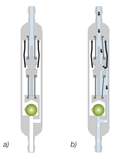

DUALSWITCH VALVE                                 GEBRAUCHSANWEISUNG | DE

INHALTSVERZEICHNIS

INDIKATION                                                             4

TECHNISCHE BESCHREIBUNG                                                4

ARBEITSWEISE DES DSV                                                   4

PHYSIKALISCHER HINTERGRUND                                             6

AUSWAHL DES GEEIGNETEN DSV                                             7

DRUCKSTUFENERKENNUNG IM RÖNTGENBILD                                    7

MÖGLICHE SHUNTKOMPONENTEN                                              8

SCHLAUCHSYSTEME                                                        8

IMPLANTATION                                                           9

ÜBERPRÜFUNG DER DURCHGÄNGIGKEIT DES VENTILS                            9

DRUCK-FLOW-CHARAKTERISTIK                                             10

REIMPLANTATION                                                        12

VORSICHTSMAẞNAHMEN UND KONTRAINDIKATIONEN                             12

POSTOPERATIVE VENTILPRÜFUNG                                           12

FUNKTIONSSICHERHEIT UND VERTRÄGLICHKEIT MIT DIAGNOSTISCHEN
VERFAHREN                                                             12

MÖGLICHE NEBENWIRKUNGEN                                               12

STERILISATION                                                         13

FORDERUNGEN DER MEDIZINPRODUKTERICHTLINIE (RL 93/42/EWG)              13

KOMMENTAR ZUR GEBRAUCHSANWEISUNG                                      13

MEDIZINPRODUKTEBERATER                                                13

ALLGEMEINE INFORMATIONEN                                              13

VARIANTEN                                                             14

                                                                       3
DE | GEBRAUCHSANWEISUNG DUALSWITCH VALVE
INDIKATION tchen wirken zwei unterschiedlich starke Bügel-
federn (5 und 6), die durch ihre Vorspannkraft
Das DUALSWITCH VENTIL (DSV) dient beim
den Öffnungsdruck bestimmen. Durch diese
Hydrocephalus zur Liquordrainage aus den
Federn werden die Druckplättchen gegen eine
Ventrikeln in das Peritoneum.
in das Gehäuse integrierte Kugel (4) gedrückt,
TECHNISCHE BESCHREIBUNG wodurch die Bohrung in den Plättchen und
dadurch das Ventil verschlossen wird. Die stär-
Das DUALSWITCH VENTIL wurde mit dem Ziel kere der beiden Federn (5) regelt das Öff-
entwickelt, die bekannten Probleme bei der nungsverhalten für die Hochdruckseite (7), die
Behandlung des Hydrocephalus (Verstopfun- schwächere Feder (6) charakterisiert das Öff-
gen des Drainagesystems, Überdrainage, Ein- nungsverhalten der Niederdruckseite (8). Eine
fluss des Subkutandrucks) zu vermeiden. Das der Niederdruckseite nachgeordnete Tantalku-
DSV besitzt zwei parallele Kammern, eine für gel (9) arbeitet als Schalter zwischen den bei-
die stehende und eine für die liegende Posi- den Druckstufen. Die Anschlusstüllen für den
tion des Patienten. Das DUALSWITCH VENTIL Einlass (10) und den Auslass (11) sind ebenfalls
besteht aus einem stabilen Titangehäuse (1), in aus Titan gefertigt.
das durch zwei Silikonmembrane (2) zwei Tit-
anplättchen (3) integriert sind. Auf diese Plät-
Abb. 1: Schematische Querschnittszeichnung des DUALSWITCH VENTILS
ARBEITSWEISE DES DSV
Das DUALSWITCH VENTIL reguliert den intra-
ventrikulären Druck für die Liegendposition
und die Stehendposition des Patienten unter-
schiedlich. Die prinzipielle Arbeitsweise des
DSV ist in Abb. 2 und Abb. 3 dargestellt.
Horizontale Körperposition
Abb. 2: Ventilzustände in der Liegendposition:
Abb. 2a zeigt das geschlossene Ventil in lie- a) geschlossen
gender Position. Beide Membrane liegen auf b) geöffnet
der Gehäusekugel auf, das Ventil lässt keine
Liquordrainage zu.
In Abb. 2b ist das DSV im geöffneten Zustand
abgebildet. Der IVP des Patienten ist erhöht, die
Federkraft auf der Niederdruckseite wird über-
wunden, die Membran von der Kugel gehoben
und ein Spalt zur Liquordrainage freigegeben.
Ein weiterer Druckanstieg wird verhindert.
4DUALSWITCH VALVE GEBRAUCHSANWEISUNG | DE
Vertikale Körperposition len) können die Arbeitsweise des Ventils stark
beeinflussen.
Sowie der Patient aufsteht, verschließt die
Um den Einfluss dieser Störkräfte zu senken,
Tantalkugel den Abflusskanal auf der Nieder-
aber eine gleiche Ventildruckstufe verwenden
druckseite. Übersteigt die Summe des IVP
zu können, muss die Öffnungskraft erhöht wer-
und des hydrostatischen Drucks nicht die Ver-
den. Die Klebekräfte sind dann im Verhältnis
schlusskraft der starken Feder, bleibt das Ventil
zur Öffnungskraft sehr klein und haben einen
geschlossen (siehe Abb. 3a).
wesentlich geringeren Einfluss auf die Arbeits-
weise des Ventils. Wenn man den gleichen Ven-
trikeldruck annimmt, kann die Öffnungskraft
konstruktiv durch eine Vergrößerung der wirk-
samen Fläche erreicht werden. Im DSV verteilt
sich der Liquor auf eine Fläche, die wesentlich
größer ist als bei anderen Ventilen. Eine Anfäl-
ligkeit gegen Verklebungen der Membran bei
eiweiß- bzw. fibrinhaltigem Liquor ist dadurch
deutlich eingeschränkt.
Um den Vorteil der großen Öffnungskräfte
zu realisieren, hat das Ventil eine Größe von
etwa 28 x 5 mm. Ähnlich wie Herzschrittma-
cher, die schon seit vielen Jahren problemlos
im Brustbereich implantiert werden, wird das
DUALSWITCH VENTIL thorakal platziert.
Abb. 3: Ventilzustände in der Stehendposition:
Abb. 4: Liquor- und Druckverteilung im geschlossenen
a) geschlossen b) geöffnet
Ventil
Erst wenn der Druck weiter steigt, öffnet sich
die Hochdruckseite des Ventils und verhindert
somit einen weiteren Druckanstieg (Abb. 3b).
Das DUALSWITCH VENTIL besitzt große wirk-
same Schaltflächen und sichert somit eine prä-
zise Arbeitsweise. Die Ventilöffnungskraft F, die
durch den Ventrikeldruck entsteht, hängt ab
von der anliegenden Höhe des Ventrikeldrucks
p und der Fläche A, auf die der Ventrikeldruck
wirkt.
Bei konventionellen Ventilen ist diese wirksame
Fläche sehr klein. Damit sind die Öffnungskräfte
ebenfalls klein. Eventuelle Störkräfte (Verkle-
bungen durch Liquorbestandteile, z. B. Blutzel-
5DE | GEBRAUCHSANWEISUNG DUALSWITCH VALVE
PHYSIKALISCHER HINTERGRUND negativ. Um diesen Druck mittels Ventildrai-
nage einzustellen, muss der Ventilöffnungs-
In der liegenden Körperposition ist der intra-
druck weit höher ausgelegt werden, als es in
ventrikuläre Druck beim gesunden Menschen
der liegenden Position nötig wäre. Nur dann
positiv. Um diesen Druck mittels Ventildrai-
kann das Ventil den hydrostatischen Druck
nage einzustellen, ist unter Berücksichtigung
abzüglich des Bauchraumdruckes und des
des Bauchraumdrucks die geeignete Druck-
gewünschten, leicht negativen intraventriku-
stufe zu wählen. Dann errechnet sich der IVP
lären Druckes kompensieren. Konventionelle
aus der Summe des Ventilöffnungsdrucks und
Ventile öffnen in der aufrechten Körperposition
des Bauchraumdrucks (Abb. 5).
sofort und es kann zu einer kritischen Überdrai-
In der stehenden Körperposition wird der Ven-
nage kommen.
trikeldruck beim gesunden Menschen leicht
Abb. 5: Druckverhältnisse für die liegende und die aufrechte Körperposition
IVP : Intraventrikulärer Druck
PL : Ventilöffnungsdruck im Liegen (nur Kugel-Konus-Ventil)
PS : Ventilöffnungsdruck im Stehen (Kugel-Konus-Ventil + Gravitationsventil)
PB : Druck in der Bauchhöhle
PH : Hydrostatischer Druck
Liegend: IVP = PL + PB
Stehend: IVP = PH - PS - PB
6DUALSWITCH VALVE GEBRAUCHSANWEISUNG | DE
AUSWAHL DES GEEIGNETEN DSV DRUCKSTUFENERKENNUNG IM
RÖNTGENBILD
Das DUALSWITCH VENTIL ist ein lageabhän-
gig arbeitendes Ventil. Es besitzt zwei verschie- Jedes DUALSWITCH VENTIL wird unter
dene Öffnungsdrücke. Ein Öffnungsdruck ist strenger Qualitätskontrolle kalibriert. Folgende
für die liegende Körperposition des Patienten Druckstufenkombinationen, die auch im Rönt-
ausgelegt, der andere Öffnungsdruck für die genbild durch eine Kodierung festgestellt wer-
stehende Körperposition. Ein perkutanes Ver- den können, sind erhältlich:
stellen der Ventilcharakteristik wird auf diese Die Kodierung der Niederdruckseite liegt immer
Weise überflüssig, da ein hoher Öffnungsdruck nahe dem Kugelschalter (weißer Punkt). Die
in der stehenden Körperposition einer unge- Kodierung der Hochdruckseite liegt immer fern
wollt hohen Drainage entgegenwirkt, im Liegen vom Kugelschalter. Dabei ist es unerheblich,
jedoch der erforderlich niedrige Öffnungsdruck auf welcher Seite vom Kugelschalter die Kodie-
eine Unterdrainage ausschließt. rung zu erkennen ist.
Liegende Körperposition
Für die liegende Körperposition stehen vier
verschiedene Öffnungsdrücke zur Verfügung
(5, 10, 13 und 16 cmH₂O). Als Stan-
darddruckstufe wird 10 cmH₂O (Ventildruck
bei einem Flow von 20 ml/h) empfoh-
len. Für Normaldruck-Hydrocephalus-Patien-
Abb. 6: Liegend 5 cmH₂O
ten steht die Druckstufe 5 cmH₂O zur Verfü-
gung.
Stehende Körperposition
Der Öffnungsdruck für die stehende Körperpo-
sition ist abhängig von der Größe des Patien-
ten (Hydrostatik). Die Auswahl der Hochdruck-
seite des Ventils erfolgt so, dass in jedem Fall
in der Stehendposition ein Ventrikeldruck von
Abb. 7: Standardventil: liegend 10 cmH₂O
mindestens -5 cmH₂O eingestellt wird. Dabei
wird folgendermaßen vorgegangen:
1. Ausmessen des Abstandes zwischen dem
dritten Ventrikel (Höhe Foramen Monroi)
und dem Zwerchfell des Patienten.
2. Von dieser Höhe werden 5 cm abgezogen.
3. Es wird ein Ventil mit einer Druckstufe auf
der Hochdruckseite ausgewählt, die grö-
ßer ist als die ausgemessene Höhendif-
Abb. 8: Liegend 13 cmH₂O
ferenz minus 5 cm und diesem Wert am
nächsten liegt. Die zur Verfügung stehen-
den Öffnungsdruckstufen betragen 30, 40
und 50 cmH₂O. Der sich einstellende Ven-
trikeldruck im Patienten liegt dann immer
zwischen -5 cmH₂O und +5 cmH₂O.
Abb. 9: Liegend 16 cmH₂O
7DE | GEBRAUCHSANWEISUNG DUALSWITCH VALVE
Ø 0.9 mm erfolgen. Es kann ohne Einschrän-
kung 30-mal punktiert werden.
WARNUNG
Durch häufiges Pumpen kann es zu einer
übermäßigen Drainage und damit zu unphy-
siologischen Druckverhältnissen kommen.
Der Patient sollte über diese Gefahr aufge-
Abb. 10: Mögliche Kodierungen (oben) und Röntgen- klärt werden.
aufnahme des DSV (Druckstufen 13/30)
Der Bohrlochumlenker bietet durch seinen
Bei Fragen oder Problemen bezüglich der Ven- strammen Sitz auf dem Ventrikelkatheter die
tilfunktion wenden Sie sich bitte an die Medizin- Möglichkeit, die in den Schädel eindringende
produkteberater der Christoph Miethke GmbH Katheterlänge vor der Implantation zu wählen.
& Co. KG. Der Ventrikelkatheter wird im Bohrloch recht-
winklig umgelenkt (siehe Kapitel „Varianten“).
MÖGLICHE SHUNTKOMPONENTEN
Das DUALSWITCH VENTIL kann in verschiede- SCHLAUCHSYSTEME
nen Varianten bestellt werden. Diese Shuntvari- Das DUALSWITCH VENTIL ist so konstru-
anten besitzen unterschiedliche Komponenten, iert, dass es nach Indikation des Arztes den
die nachfolgend kurz vorgestellt werden. Dabei optimalen Ventrikeldruck sicherstellt. Es kann
gibt es Varianten für den kindlichen und wei- als DUALSWITCH VENTIL-Shuntsystem oder
tere für den Erwachsenenhydrocephalus. Das als einzelne Ventileinheit mit oder ohne inte-
SPRUNG RESERVOIR oder das Bohrlochre- griertem distalen Katheter (Innendurchmesser
servoir werden im Bohrloch der Schädelde- 1,2 mm, Außendurchmesser 2,5 mm) bestellt
cke positioniert und bieten die Möglichkeit, den werden. Wird eine einzelne Ventileinheit einge-
intraventrikulären Druck zu messen, Medika- setzt, sollten Katheter mit einem Innendurch-
mente zu injizieren und Liquor zu entnehmen. messer von ca. 1,2 mm und einem Außen-
Ein stabiler Titanboden verhindert ein mögli- durchmesser von ca. 2,5 mm verwendet wer-
ches Durchstechen des Bodens. Das SPRUNG den. Der Konnektor am Ventil ermöglicht die
RESERVOIR ermöglicht zusätzlich durch ein Verwendung von Kathetern mit einem Innen-
Rückschlagventil im Boden den Liquor in die durchmesser von 1,0 mm bis 1,5 mm. Der
ableitende Richtung zu pumpen und damit Außendurchmesser des Katheters sollte etwa
sowohl eine Kontrolle des distalen Drainagean- dem doppelten Innendurchmesser entspre-
teils (Reservoir schwer ausdrückbar), als auch chen. Eine Ausnahme stellt die lumbo-perito-
des Ventrikelkatheters (Reservoir füllt sich nach neale Ableitung dar. Hier kann an das Ven-
Ausdrücken nicht erneut) durchzuführen. Wäh- til bzw. an das Reservoir ein lumbaler Kathe-
rend des Pumpvorganges ist der Zugang zum ter angeschlossen werden. In jedem Fall müs-
Ventrikelkatheter verschlossen. Der Öffnungs- sen die Katheter durch eine Ligatur sorgfäl-
druck des Shuntsystems wird durch den Ein- tig an den Konnektoren des Ventils befes-
satz des SPRUNG RESERVOIRS nicht erhöht. tigt werden. Knicke in den Kathetern müssen
Das CONTROL RESERVOIR oder die Vorkam- vermieden werden. Die mitgelieferten Katheter
mer werden auf der Schädeldecke positio- verändern die Druck-Flow-Charakteristik nicht
niert und bieten als Vorkammer die Möglichkeit, grundlegend.
den intraventrikulären Druck zu messen, Medi-
kamente zu injizieren, Liquor zu entnehmen
und eine palpatorische Ventilkontrolle durch-
zuführen. Ähnlich dem SPRUNG RESERVOIR
besitzt das CONTROL RESERVOIR ein Rück-
schlagventil. Ein stabiler Titanboden verhin-
dert ein mögliches Durchstechen des Bodens.
Eine Punktion sollte möglichst senkrecht zur
Reservoiroberfläche mit einer Kanüle von max.
8DUALSWITCH VALVE GEBRAUCHSANWEISUNG | DE
IMPLANTATION wird der Katheter, abhängig vom verwendeten
System, entweder vom Bohrloch zum gewähl-
Platzierung Ventrikelkatheter ten Ventilimplantationsort vorgeschoben oder
Zur Platzierung des Ventrikelkatheters sind ver- entgegengesetzt. Bei einer lumbo-peritonealen
schiedene Operationstechniken möglich. Der Ableitung empfiehlt sich der Rippenbogen als
notwendige Hautschnitt sollte bevorzugt in Implantationsort.
Form eines Läppchens mit Stielung in Richtung
auf den ableitenden Katheter, nur in Ausnah- WARNUNG
mefällen durch einen geraden Hautschnitt erfol-
Die Katheter sollten nur mit armierten
gen. Es sollte darauf geachtet werden, dass Klemmchen, nicht direkt hinter dem Ventil
nach Anlage des Bohrlochs die Öffnung der unterbunden werden, da sie sonst geschä-
Dura möglichst klein erfolgt, um ein Liquorleck digt werden könnten.
zu vermeiden. Der Ventrikelkatheter wird durch
den beiliegenden Mandrin versteift. WARNUNG
Durch häufiges Pumpen kann es zu einer
Das DUALSWITCH VENTIL ist in verschie- übermäßigen Drainage und damit zu unphy-
denen Shuntvarianten erhältlich: Bei Verwen- siologischen Druckverhältnissen kommen.
dung eines DSV-Shuntsystems mit SPRUNG Der Patient sollte über diese Gefahr aufge-
RESERVOIR oder Bohrlochreservoir wird zuerst klärt werden.
der Ventrikelkatheter implantiert. Nach dem
Entfernen des Mandrins kann die Durchgän- Platzierung des Peritonealkatheters
gigkeit des Ventrikelkatheters durch Heraus- Der Ort des Zugangs für den Peritonealkatheter
tropfen von CSF geprüft werden. Der Kathe- liegt im Ermessen des Chirurgen. Er kann z. B.
ter wird gekürzt und das Bohrlochreservoir waagerecht paraumbilikal oder in Höhe des
konnektiert, wobei die Konnektion mit einer Epigastriums angelegt werden. Ebenso kön-
Ligatur gesichert wird. Der Hautschnitt sollte nen verschiedene Operationstechniken für die
nicht unmittelbar über dem Reservoir liegen. Platzierung des Peritonealkatheters angewen-
Bei der Verwendung eines DSV-Shuntsystems det werden.
mit CONTROL RESERVOIR oder mit Vorkam- Es wird empfohlen, den Peritonealkatheter mit
mer liegt ein Bohrlochumlenker bei. Mit Hilfe Hilfe eines subkutanen Tunnelers vom Ven-
dieses Umlenkers kann die zu implantierende til aus, eventuell mit einem Hilfsschnitt, bis
Katheterlänge eingestellt und in den Ventrikel zum Ort der Platzierung durchzuziehen. Der
vorgeschoben werden. Der Ventrikelkatheter Peritonealkatheter, der in der Regel fest am
wird umgelenkt, die Pumpkammer platziert. Die DUALSWITCH VENTIL befestigt ist, besitzt ein
Position des Ventrikelkatheters sollte nach der offenes distales Ende und keine Wandschlitze.
Operation durch ein bildgebendes Verfahren Nach Darstellung und Entrieren des Peritone-
(z.B. CT, MRT) kontrolliert werden. ums oder mit Hilfe eines Trokars wird der, wenn
notwendig gekürzte, Peritonealkatheter in die
Platzierung des Ventils freie Bauchhöhle vorgeschoben.
Das DUALSWITCH VENTIL arbeitet lageabhän-
ÜBERPRÜFUNG DER DURCHGÄNGIG-
gig. Es muss deshalb darauf geachtet werden,
KEIT DES VENTILS
dass die Konnektorachse des Ventils möglichst
parallel zur Körperachse implantiert wird. Das möglichst schonende Befüllen des
Die Implantation erfolgt subkutan entweder DUALSWITCH VENTIL kann durch Aspirieren
supra- oder knapp infraclaviculär. Das Ventil ist mithilfe einer am distalen Katheterende aufge-
mit einem Pfeil für die Flussrichtung nach dis- setzten sterilen Einwegspritze erfolgen. Dabei
tal hin versehen (Pfeil nach unten). Das Ventil wird das proximale Ende des Ventils in ste-
wird in eine subkutane Tasche flach implantiert, rile, physiologische Kochsalzlösung gehalten.
wobei für die Funktion nicht ausschlaggebend Lässt sich Flüssigkeit entnehmen, ist das Ventil
ist, ob die Beschriftung zur Haut- oder zur Rip- durchgängig (siehe Abb. 7).
penseite zu liegen kommt.
Nach Hautschnitt und Untertunnelung der Haut
9DE | GEBRAUCHSANWEISUNG DUALSWITCH VALVE
Abb. 11: Durchgängigkeitsprüfung
a) isotonische Kochsalzlösung
VORSICHT
Eine Druckbeaufschlagung mittels Einweg-
spritze sollte sowohl am proximalen als
auch am distalen Ende vermieden werden.
Verunreinigungen in der zum Testen ver-
wendeten Lösung können die Produktleis-
tung beeinträchtigen.
DRUCK-FLOW-CHARAKTERISTIK
Nachfolgend sind die Druck-Flow-Charakteris-
tiken der Druckstufen des DSV dargestellt. Der
gesamte Öffnungsdruck bezieht sich auf einen
Referenzflow von 5 ml/h. Für Flussraten von
20 ml/h sind die angegebenen Drücke ca. 1 bis
2 cmH₂O höher.
10DUALSWITCH VALVE GEBRAUCHSANWEISUNG | DE
11DE | GEBRAUCHSANWEISUNG DUALSWITCH VALVE
REIMPLANTATION Liegendposition in der Hochdruckstufe arbei-
tet, was den Austausch des Ventils erforderlich
Produkte, die bereits implantiert waren, dürfen
macht.
weder bei dem gleichen noch bei einem ande-
ren Patienten erneut implantiert werden.
VORSICHTSMAẞNAHMEN UND KON-
TRAINDIKATIONEN
Nach der Implantation müssen die Patien-
ten sorgfältig überwacht werden. Hautrötungen
und Spannungen im Bereich des Drainagege-
webes können ein Anzeichen von Infektionen Abb. 12: DSV im Röntgenbild
am Shuntsystem sein. Symptome wie Kopf- a) stehende Position
schmerzen, Schwindelanfälle, geistige Verwirrt- b) liegende Position
heit oder Erbrechen treten häufig bei einer
Shuntdysfunktion auf. Diese Anzeichen wie
FUNKTIONSSICHERHEIT
auch eine Leckage am Shuntsystem, erfordern UND VERTRÄGLICHKEIT MIT
den sofortigen Austausch der Shuntkompo- DIAGNOSTISCHEN VERFAHREN
nente oder auch des gesamten Shuntsystems.
Die Implantation von Medizinprodukten ist kon- Die Medizinprodukte sind konstruiert worden,
traindiziert, sofern beim Patienten eine Infektion um über lange Zeiträume präzise und zuverläs-
(z. B. Meningitis, Ventrikulitis, Peritonitis, Bakte- sig zu arbeiten. Es kann jedoch keine Garantie
riämie, Septikämie) oder der Verdacht auf eine dafür übernommen werden, dass die Medizin-
Infektion in der von der Implantation betroffenen produkte aus technischen oder medizinischen
Körperregion vorliegt. Gründen ausgetauscht werden müssen. Die
Medizinprodukte halten während und nach der
POSTOPERATIVE VENTILPRÜFUNG Operation auftretenden negativen und positi-
ven Drücken von bis zu 100 cmH₂O sicher
Das DUALSWITCH VENTIL ist als funktionssi- stand. Die Medizinprodukte sind stets trocken
chere Einheit ohne Pump- oder Prüfeinrichtung und sauber zu lagern.
konstruiert worden. Es bestehen aber Mög- Kernspinresonanzuntersuchungen bis zu einer
lichkeiten zum Testen bei Verwendung eines Feldstärke von 3 Tesla oder computertomogra-
Reservoirs (siehe Kapitel “Mögliche Shuntkom- phische Untersuchungen können ohne Gefähr-
ponenten”). dung oder Beeinträchtigung der Ventilfunktion
Daneben kann die Prüfung der Schaltung der durchgeführt werden. Das Ventil ist bedingt
Tantalkugel durch Röntgen-Aufnahmen des MR-sicher. Die mitgelieferten Katheter sind
Ventils in stehender und liegender Körper- MR-sicher. Reservoire, Umlenker und Konnek-
haltung geprüft werden. Die Tantalkugel, die toren sind bedingt MR-sicher.
als Schalter zwischen den beiden Ventilstufen Die Bedingungen für die MR-Kompatibilität der
fungiert, erscheint im Röntgenbild als nahezu Produkte finden Sie auf unserer Website:
weißer Kreis. In der Aufnahme in der liegen- https://www.miethke.com/downloads/
den Position muss in Flussrichtung unmittelbar
unterhalb der Kugel ein dunkler Schatten sicht- MÖGLICHE NEBENWIRKUNGEN
bar sein, der in der Aufnahme für die Stehend-
position nicht erkennbar ist. Sollte unabhän- Bei der Hydrocephalustherapie mit Shunts kön-
gig von der Position des Patienten ein Schat- nen, wie in der Literatur beschrieben, Kompli-
ten (länglicher Balken, siehe Abb. 8b) erkennbar kationen auftreten, dazu gehören Infektionen,
sein, bedeutet dies, dass die Tantalkugel auch Verstopfungen durch Eiweiss und/oder Blut im
in der Stehendposition nicht schließt. In diesem Liquor, Über-/Unterdrainage oder in sehr selte-
Fall arbeitet das Ventil wie konventionelle Dif- nen Fällen Geräuschentwicklungen. Durch hef-
ferenzdruckventile. Sollte unabhängig von der tige Stöße von außen (Unfall, Sturz etc.) kann
Haltung des Patienten kein Schatten erkennbar die Integrität des Shunts gefährdet werden.
sein, bedeutet dies, dass das Ventil auch in der
12DUALSWITCH VALVE GEBRAUCHSANWEISUNG | DE
STERILISATION ALLGEMEINE INFORMATIONEN
Die Produkte werden unter strenger Kontrolle
mit Dampf sterilisiert. Das jeweilige Verfallsda-
tum ist auf der Verpackung angegeben. Bei
Hersteller Christoph Miethke
Beschädigung der Verpackung dürfen die Pro- GmbH & Co. KG
dukte auf keinen Fall verwendet werden. Für die
Funktionssicherheit von resterilisierten Produk- Produkt- DUALSWITCH VENTIL
ten kann keine Garantie übernommen werden. bezeichung
Verwendungs- Behandlung des Hydro-
FORDERUNGEN DER MEDIZINPRODUK-
TERICHTLINIE (RL 93/42/EWG) zweck cephalus
Die Medizinprodukterichtlinie fordert die umfas- Zum einmaligen Gebrauch bestimmt
sende Dokumentation des Verbleibs von Trocken und sauber lagern
medizinischen Produkten, die am Menschen
zur Anwendung kommen, insbesondere für Skizze des Ventils mit äußeren Maßen:
Implantate. Die individuelle Kenn-Nummer des
Implantats sollte aus diesem Grund in der Kran-
kenakte und im Patientenpass des Patienten
vermerkt werden, um eine lückenlose Rückver-
folgbarkeit zu gewährleisten. Die Übersetzung
dieser Gebrauchsanweisung in weitere Spra-
chen finden Sie auf unserer Website:
https://www.miethke.com/downloads/
KOMMENTAR ZUR GEBRAUCHSAN-
WEISUNG
Die hier ausgeführten Beschreibungen basieren
auf den bisher vorliegenden klinischen Erfah-
rungen. Es liegt in der Hand des Chirurgen,
entsprechend seiner Erfahrung und der chirur-
gischen Praxis auf eigene Verantwortung das
OP-Prozedere zu ändern.
MEDIZINPRODUKTEBERATER
Die Christoph Miethke GmbH & Co. KG
benennt entsprechend den Forderungen
der Medizinprodukterichtlinie (RL 93/42/EWG)
Medizinprodukteberater, die Ansprechpartner
für alle produktrelevanten Fragen sind.
Sie erreichen unsere Medizinprodukteberater
unter:
Tel. +49 331 62083-0
info@miethke.com DUALSWITCH VENTIL ohne integrierten
Katheter
13DE | GEBRAUCHSANWEISUNG DUALSWITCH VALVE VARIANTEN Das DSV ist als Einzelventil oder als Shuntsystem mit unterschiedlichen Komponenten erhältlich. Alle Abbildungen in diesem Kapitel sind im Maßstab 1:1. Abb. 13: DUALSWITCH VENTIL Abb. 14: DUALSWITCH-Shuntsystem (ohne Reservoir) Abb. 15: DUALSWITCH-Shuntsystem mit SPRUNG RESERVOIR oder Bohrlochreservoir (auch für pädiatrische Anwendung) Abb. 16: DUALSWITCH-Shuntsystem mit CONTROL RESERVOIR oder Vorkammer (auch für pädiatrische Anwen- dung) 14
DUALSWITCH VALVE                                    GEBRAUCHSANWEISUNG | DE

Abb. 17: DUALSWITCH-Shuntsystem für L-P-Ableitung

                                                                         15
EN | INSTRUCTIONS FOR USE DUALSWITCH VALVE TABLE OF CONTENTS INDICATION 17 TECHNICAL DESCRIPTION 17 FUNCTION OF THE DUALSWITCH VALVE 17 PHYSICAL BACKGROUND 19 SELECTING THE APPROPRIATE DSV SHUNT SYSTEM 20 READING THE PRESSURE SETTING FROM AN X-RAY IMAGE 20 POSSIBLE SHUNT COMPONENTS 21 TUBE SYSTEMS 21 IMPLANTATION 21 TESTING THE VALVE PATENCY 22 PRESSURE-FLOW CHARACTERISTICS 22 RE-IMPLANTATION 24 SAFETY MEASURES AND CONTRAINDICATIONS 24 POSTOPERATIVE VALVE TEST 24 FUNCTIONAL SAFETY AND COMPATIBILITY WITH DIAGNOSTIC PROCEDURES 25 ADVERSE REACTIONS 25 STERILISATION 25 REQUIREMENTS OF THE MEDICAL DEVICE DIRECTIVE (DIRECTIVE 93/42/EEC) 26 NOTE ON THE INSTRUCTIONS FOR USE 26 MEDICAL DEVICES CONSULTANTS 26 GENERAL INFORMATION 26 VARIANTS 27 16
DUALSWITCH VALVE                                                       INSTRUCTIONS FOR USE | EN

INDICATION                                             ted to the casing by two silicone membranes
                                                       (2). Two yoke springs (5), (6) of different strength
The DUALSWITCH VALVE is used for fluid
                                                       act on these discs and determine the open-
drainage from the ventricles into the peritoneum
                                                       ing pressure with their respective preload force.
in cases of hydrocephalus.
                                                       The springs press the pressure discs against a
TECHNICAL DESCRIPTION                                  ball (4) integrated into the casing. In this way,
                                                       the drill holes in the discs are closed and the
The DUALSWITCH VALVE was developed with                valve is closed. The stronger one of the two
the aim to avoid known problems (blocked               springs (5) controls the opening and closing for
drainage system, overdrainage, influence of the        the high-pressure side (7); the weaker spring
subcutaneous pressure) in the treatment of             (6) determines the opening and closing of the
hydrocephalus. The DUALSWITCH VALVE fea-               lowpressure side (8). A secondary tantalum ball
tures two parallel chambers, one for the patient       (9) on the lowpressure side acts as the switch
vertical and one for the horizontal position.          between the two pressure levels. Inlet port (10)
Fig. 1 shows a schematic cross section of the          and outlet port (11) are also made of titanium.
DUALSWITCH VALVE. The robust titanium cas-
ing (1) contains two titanium discs (3) connec-

Fig. 1: Schematic cross-section of the DUALSWITCH VALVE

FUNCTION OF THE DUALSWITCH VALVE

The DUALSWITCH VALVE regulates the intra-
ventricular pressure in different ways depend-
ing on the position of the patient (vertical or hor-
izontal). The operating principle of the DSV is
illustrated in figures 2 and 3.

Horizontal position
                                                       Fig. 2: Valve states in the lying-down postion:
Fig. 2a shows the closed valve in the lying-           a) closed
down position. Both membranes are pressed              b) open
onto the casing ball; the valve blocks any fluid
drainage.
Fig. 2b shows the valve open (lying-down posi-
tion). The IVP of the patient has risen, the spring
pressure on the low-pressure side is overcome,
and the membrane is pressed up from the ball,
thereby opening a gap for fluid drainage. The
pressure cannot rise any further.

                                                                                                         17
EN | INSTRUCTIONS FOR USE DUALSWITCH VALVE
Vertical position cells) can severely impair the valve’s functional-
ity.
As soon as the patient rises, the tantalum ball
To minimize the effects of such interfering
closes the drainage channel on the low-pres-
forces, but still be able to use the same valve
sure side. As long as the sum of the IVP and
pressure rating, the opening force needs to be
the hydrostatic pressure does not exceed the
increased. In this way, the sticking forces will
closing force of the stronger spring, the valve
be very small compared to the opening force
remains closed, see fig. 3a.
so that their influence on valve performance is
reduced considerably. Assuming the ventricular
pressure is unchanged, the opening force can
be increased by providing for a larger active sur-
face in the valve design. In the DUALSWITCH
VALVE, the fluid is distributed over a surface
significantly larger than in conventional valves.
Therefore the valve is much less susceptible to
conglutinations of the membrane through pro-
teins (fibrin)-rich cerebrospinal fluid.
To realize the advantage of strong opening
forces, the valve is about 28 x 5 mm in size. The
DSV is placed in the thoracic region, like car-
diac pacemakers, which have been implanted
there successfully for many years.
Fig. 4: Fluid and pressure distribution in the closed valve
Fig. 3: Valve states in the vertical position:
a) closed b) open
Only if the pressure rises further, the high-pres-
sure side of the valve opens and thereby pre-
vents any further pressure rise, see fig. 3b.
The DUALSWITCH VALVE has large active
switching surfaces, which ensures precise
operation. The valve opening force, F, which is
brought about by ventricular pressure, is gov-
erned by the level of ventricular pressure, p, and
the surface, A, on which the ventricular pres-
sure acts.
In conventional valves this active surface is very
small. Consequently, the valve opening forces
are small as well. Thus, countervailing forces
(sticking caused by fluid residues, e. g. blood
18DUALSWITCH VALVE INSTRUCTIONS FOR USE | EN
PHYSICAL BACKGROUND tive. To regulate ventricular pressure using
shunt valve drainage, valve opening pressure
In the lying-down position, the intraventricu-
in standing position must be set consider-
lar pressure is positive in a healthy human. To
ably higher. Only in this way can the shunt
adjust this pressure using valve drainage, only
valve compensate for the hydrostatic pressure
the pressure in the abdominal cavity has to be
reduced by the pressure in the abdominal cav-
taken into account.
ity. Conventional valves open instantly, as soon
Fig. 5 illustrates the calculation of the intraven-
as the patient rises to a standing position, and
tricular pressure for the horizontal and standing
a critical overdrainage may occur.
body position. In the standing body position,
the ventricular pressure should be slightly nega-
Fig. 5: Pressure situation at the shunt for horizontal and vertical position
IVP : Intraventricular pressure
PL : Opening pressure in horizontal position (adjustable DP unit only)
PS : Opening pressure in vertical position (adjustable DP unit + gravitational unit)
PB : Pressure in the abdominal cavity
PH : Hydrostatic pressure
Horizontal: IVP = PL + PB
Vertical: IVP = PH - PS - PB
19EN | INSTRUCTIONS FOR USE DUALSWITCH VALVE
SELECTING THE APPROPRIATE DSV READING THE PRESSURE SETTING
SHUNT SYSTEM FROM AN X-RAY IMAGE
The mode of operation of the DUALSWITCH Strict quality control is applied in the calibration
VALVE depends on the position of the patient. It of each individual DUALSWITCH VALVE. The
features two different opening pressures. One following pressure level combinations, which
opening pressure is effective when the patient can also be read from an X-ray visible coding,
is in a horizontal position; the other is for the are available:
patient standing upright. Percutaneous read- The code for the low-pressure side is always
justment of the valve characteristics is unnec- situated close to the ball switch (white dot). The
essary, since the higher opening pressure in the code for the high-pressure side is always further
upright position counteracts any unintentional away from the ball switch, no matter on which
overdrainage, while the lower opening pres- side of the ball switch the code is visible.
sure in the horizontal position prevents under-
drainage.
Horizontal position
For the horizontal position, four different open-
ing pressure ratings are available (5, 10, 13 and
16 cmH₂O). The recommended standard pres-
sure rating is 10 cmH₂O (valve pressure at a
Fig. 6: Horizontal 5 cmH₂O
flow of 20 ml/h). The pressure rating 5 cmH₂O
is available for normal pressure hydrocephalus
patients.
Vertical position
The opening pressure for the standing posi-
tion depends on the body height of the patient
(hydrostatics). The high-pressure side of the
valve is chosen in such a way that, with the
Fig. 7: Standard valve: horizontal 10 cmH₂O
patient standing upright, a ventricular pressure
of at least -5 cmH₂O is maintained under all cir-
cumstances. The procedure is the following:
1. The distance between the third ventricle (at
the levelof the Foramen Monroi) and the
diaphragm of the patient is measured.
2. 5 cm are subtracted from the measured
distance.
3. The valve is chosen whose pressure rat-
ing for the high-pressure side exceeds the Fig. 8: Horizontal 13 cmH₂O
measured distance minus 5 cm by the
smallest amount. The available opening
pressure ratings are 30, 40 and 50 cmH₂O.
The ventricular pressure in the patient will
then be kept between -5 cmH₂O and
+5 cmH₂O at all times.
Fig. 9: Horizontal 16 cmH₂O
20DUALSWITCH VALVE INSTRUCTIONS FOR USE | EN
tion of the ventricular catheter is avoided dur-
ing the pumping procedure. The opening pres-
sure of the shunt system is not increased by the
implantation of the CONTROL RESERVOIR.
WARNING
Frequent pumping can lead to overdrainage
and thus to unphysiological pressure condi-
Fig. 10: Possible codes (top picture) and an X-ray image
tions. The patient should be informed about
of the DUALSWITCH VALVE (pressure ratings 13/30)
the risk.
In case of questions or problems concerning
TUBE SYSTEMS
the valve functionality, please contact the med-
ical products advisors at Christoph Miethke The DSV has been designed to ensure the
GmbH & CO. KG. optimal ventricular pressure. It is available as
a shunt system or as individual valve units
POSSIBLE SHUNT COMPONENTS with or without an integrated distal catheter
The DSV is available with different shunt acces- (internal diameter 1.2 mm, external diameter
sories. These variants are comprised of a vari- 2.5 mm). Individual valve units should be used
ety of components, which are described briefly with catheters of approx. 1.2 mm internal diam-
introduced below: eter and approx. 2.5 mm external diameter. The
connector on the valve allows using catheters
The burr hole reservoir is positioned in the cra- of 1.0 mm to 1.5 mm internal diameter. The
nial burr hole. It allows measuring the intraven- external diameter of the catheter should be
tricular pressure, injecting drugs and extract- about double the internal diameter. This rule
ing CSF. Its solid titanium base is highly punc- does not apply where the valve is used for
ture-resistant. All reservoirs are available with lumboperitoneal drainage. In this case, a lum-
integrated catheters or connectors. A special bar catheter can be connected to the valve
burr hole reservoir is the SPRUNG RESERVOIR. or the reservoir, respectively. In any case, the
As additional new feature of this reservoir CSF catheters must be carefully fixed, with a lig-
can be flushed towards the valve because of ature, to the valve connectors. Kinks in the
a one-way valve in the bottom of the reser- catheter have to be avoided. The provided
voir. By this mechanism a flow in the direc- catheters have virtually no effect on the pres-
tion of the ventricular catheter is avoided dur- sureflow characteristics.
ing the pumping procedure. The opening pres-
IMPLANTATION
sure of the shunt system is not increased by the
implantation of the SPRUNG RESERVOIR.
Positioning the ventricular catheter
Several surgical techniques are available for
The prechamber is positioned on the cranium. It
positioning the ventricular catheter. The neces-
allows measuring the intraventricular pressure,
sary skin incision should be carried out, prefer-
injecting drugs, extracting CSF and perform-
ably, in the shape of a lobule pedicled towards
ing a palpatory ventricle inspection. Its solid
the draining catheter or as a straight skin inci-
titanium base is highly puncture-resistant. A
sion. To avoid CSF leakage, care should be
puncture of the prechamber or the CONTROL
taken that the dura opening is kept as small as
RESERVOIR should be performed as perpen-
possible after applying the burr hole. The ven-
dicular to the reservoir surface as possible with
tricular catheter is stiffened by the introducing
a cannula of max. 0,9 mm. 30 times of punc-
stylet supplied with the product.
tures are able without any restrictions. A spe-
cial prechamber is the CONTROL RESERVOIR.
The DSV is available in different shunt variants:
As an additional new feature of this reservoir,
When using a DSV shunt system with burr hole
CSF can be flushed towards the valve because
reservoir or SPRUNG RESERVOIR, the ventric-
of a one-way valve in the proximal inlet of the
ular catheter is implanted first. Once the intro-
reservoir. By this mechanism a flow in the direc-
21EN | INSTRUCTIONS FOR USE DUALSWITCH VALVE
ducing stylet has been removed, the patency of Positioning the peritoneal catheter
the ventricular catheter can be tested by check-
The access site for the peritoneal catheter is left
ing if CSF is dripping out. The catheter is short-
to the surgeon’s discretion. It can be applied
ened and the burr hole reservoir is connected,
e. g. para-umbilically in a horizontal direction or
with the connection secured with a ligature.
at the height of the epigastrium. Likewise, var-
The skin incision should not be located directly
ious surgical techniques are available for posi-
above the reservoir.
tioning the peritoneal catheter. We recommend
The DSV shunt system with prechamber or
pulling through the peritoneal catheter, using a
CONTROL RESERVOIR comes with a deflec-
subcutaneous tunneling tool and perhaps with
tor. This deflector is used for adjusting the posi-
an auxiliary incision, from the shunt to intended
tion of deflection before implantation of the ven-
position of the catheter.
tricular catheter. The catheter is deflected; the
The peritoneal catheter, which is usually
prechamber is put into place. The position of
securely attached to the DSV, has an open dis-
the ventricular catheter should be inspected
tal end, but no wall slits. Following the exposure
again by postoperative CT or MR imaging.
of, and the entry into, the peritoneum by means
of a trocar, the peritoneal catheter (shortened,
Positioning the valve
if necessary) is pushed forward into the open
The mode of operation of the DUALSWITCH
space in the abdominal cavity.
VALVE depends on the body position of the
patient. Therefore, care must be taken to TESTING THE VALVE PATENCY
ensure that the connector axis is implanted
parallel to the body axis, as far as possible. The DSV can be filled most gently by aspiration
The implantation is performed subcutaneously, through a sterile, single-use syringe attached to
either supraclavicular or just infraclavicular. The the distal end of the catheter. The proximal end
valve is marked with an arrow pointing dis- of the valve is immersed in a sterile, physiologi-
tally (downward) to indicate the flow direction. cal saline solution. The valve is patent if fluid can
The valve is implanted flat in a subcutaneous be extracted in this way (see fig. 7).
pocket; the orientation of the labeling (towards
the skin or towards the ribs) does not affect the
valve functionality.
Following the incision and the tunneling under
the skin, the catheter is either pushed from the
borehole to the chosen valve implantation site
or the other way round, depending on which
system is used. For lumboperitoneal drainage,
we recommend choosing the arcus costalis as
the implant position.
WARNING
Fig. 11: Patency test
The adjustable unit must be placed over a) isotonic sterile sodium chloride solution
a hard boney surface and should not be
implanted within an area, which makes find-
CAUTION
ing and feeling the valve more difficult (e. g.
under a scar).
Pressure admission through the single-use
syringe should be avoided, both at the prox-
WARNING
imal and the distal end. Contaminations in
the solution used for the test can impair the
Frequent pumping can lead to overdrainage
product’s performance.
and thus to unphysiological pressure condi-
tions. The patient should be informed about
PRESSURE-FLOW CHARACTERISTICS
the risk.
The diagrams below show the pressure-flow
characteristics for the pressure ratings in which
22DUALSWITCH VALVE INSTRUCTIONS FOR USE | EN
the DUALSWITCH VALVE is available. The total
opening pressure refers to a reference flow
of 5 ml/h. When the flowrates reach 20 ml/h,
the opening pressures are approximately 1 to
2 cmH₂O higher.
23EN | INSTRUCTIONS FOR USE DUALSWITCH VALVE
RE-IMPLANTATION
Products that have previously been implanted
must not subsequently be reimplanted into the
same or another patient.
SAFETY MEASURES AND CONTRAINDI-
CATIONS
The patients must be carefully monitored after
the implantation. Reddened skin and tension
in the area of the drainage tissue could indi-
cate infections at the shunt system. Symptoms
such as headache, dizzy spells, mental confu-
sion or vomiting are common occurrences in
cases of shunt dysfunction. Such symptoms,
as well as shunt system leakage, necessitate
the immediate replacement of the shunt com-
ponent responsible, or of the entire shunt sys-
tem.
The implantation of medical devices is con-
traindicated if the patient has an infection or
suspected infection (e. g. meningitis, ventriculi-
tis, peritonitis, bacteriaemia, septicaemia) in the
region affected by the implantation.
POSTOPERATIVE VALVE TEST
The DUALSWITCH VALVE was designed as a
safe and reliable unit operating without a pump
or test equipment, so as to prevent unwanted
interference by unauthorized or unqualified per-
sons. However, there are ways of testing if
the prechamber or the burr hole reservoir is
used. Apart from that, the functioning of the
tantalum ball switch can be checked by means
of X-ray imaging of the valve with the patient
standing upright and lying down. The tantalum
ball, which switches between the two valve lev-
els, appears as a nearwhite circle in the X-ray
picture. In the picture for the horizontal posi-
24DUALSWITCH VALVE INSTRUCTIONS FOR USE | EN
tion, a dark shadow must be visible directly FUNCTIONAL SAFETY AND
below the ball, in the direction of the fluid flow; COMPATIBILITY WITH DIAGNOSTIC
PROCEDURES
this shade is not visible in the picture for the
upright position. A shadow being visible inde- These medical devices are constructed in such
pendent of the patient’s position (oblong bar, a way as to ensure their precise and reli-
see fig. 8b) means that the tantalum ball does able operation over long periods of time. How-
not close when the patient stands up. In this ever, we cannot guarantee that these medical
case, the valve operates like a conventional dif- devices will require replacement for medical or
ferential pressure valve. If no shadow is visible, technical reasons. These medical devices are
independent of the patient’s position, the valve able to resist positive and negative pressures
operates in high-pressure mode even when the up to 100 cmH₂O during and after implantation.
patient is lying down, which means that the These medical devices have to be stored in a
valve must be replaced. clean and dry environment at all times.
Nuclear magnetic resonance (MRI) examina-
tions up to a field strength of 3 Tesla or com-
puted tomography (CT) examinations can be
performed without risk or impairment to the
valve function. The valve is MR Conditional. The
supplied catheters are MR Safe. Reservoirs,
deflectors and connectors are MR Conditional.
The conditions for MR compatibility of the
Fig. 12: DUALSWITCH VALVE in
products can be found on our website:
a) vertical position
https://www.miethke.com/downloads/
b) horizontal position
ADVERSE REACTIONS
In the treatment of hydrocephalus with shunts,
the following complications may arise (as
described in the literature): infections, block-
ages caused by protein and/or blood in the
cerebrospinal fluid, over/under drainage or in
very rare cases, noise development. Due to vio-
lent shocks from the outside (accident, fall etc.)
the integrity of the shunt may be endangered.
STERILISATION
The products are sterilised with steam under
strictly controlled conditions. The expiry date is
printed on the wrapping of each individual prod-
uct. If the packaging is damaged, the product
must not be used in any circumstances. No
guarantee can be given for the functional safety
and reliability of resterilised products.
25EN | INSTRUCTIONS FOR USE DUALSWITCH VALVE
REQUIREMENTS OF THE GENERAL INFORMATION
MEDICAL DEVICE DIRECTIVE
(DIRECTIVE 93/42/EEC) Manufacturer Christoph Miethke
GmbH & Co. KG
The Medical Device Directive requires com-
prehensive documentation of the fate of med- Product name DUALSWITCH VALVE
ical devices used in humans, especially for
Intended use Treatment of
implants. The individual implant identification
hydrocephalus
number should therefore be recorded in the
patient’s medical records and patient card to Intended for one-time use (disposable)
ensure complete traceability. Translations of
Store in a clean, dry place
these instructions for use into additional lan-
guages can be found on our website: Drawing of the valve with the outer dimen-
https://www.miethke.com/downloads/ sions in mm:
NOTE ON THE INSTRUCTIONS FOR USE
The descriptions and instructions given above
are based on clinical experience available to
date. The shunt systems have been implanted
according to the instructions given in this doc-
ument, in clinical trials. It is the responsibility
of the individual surgeon to change procedures
according to her/his experience and surgical
practice. He or she also does so at their own
risk.
However, the valve should always be implanted
in the thorax area (or, in case of L-P drainage, on
the arcus costalis), and not in the region of the
head. Implantation in the thorax area ensures
that the valve switches to the appropriate pres-
sure mode when the patient changes his or her
position.
MEDICAL DEVICES CONSULTANTS
In compliance with the European Directive con-
cerning medical devices (Directive 93/42/EEC),
Christoph Miethke GmbH & Co. KG has nomi-
nated medical devices consultants as contacts
for all product-related questions.
You can contact our medical devices consul-
tants via:
Tel. +49 331 62083-0 DUALSWITCH VALVE without integrated
info@miethke.com catheter
26DUALSWITCH VALVE INSTRUCTIONS FOR USE | EN
VARIANTS
The DSV is available as a single valve or as a shunt system comprising various components. All
figures in this chapter are to scale (1:1).
Fig. 13: DUALSWITCH VALVE
Fig. 14: DUALSWITCH shunt system (without reservoir)
Fig. 15: DUALSWITCH shunt system with SPRUNG RESERVOIR or burr hole reservoir (adult and pediatric)
Fig. 16: DUALSWITCH shunt system mit CONTROL RESERVOIR oder Vorkammer (adult and pediatric)
27EN | INSTRUCTIONS FOR USE DUALSWITCH VALVE Fig. 17: DUALSWITCH shunt system for L-P drainage 28
DUALSWITCH VALVE                                            MODE D'EMPLOI | FR

TABLE DES MATIÈRES

INDICATION                                                                  30

DESCRIPTION TECHNIQUE                                                       30

FONCTIONNEMENT DE LA DUALSWITCH VALVE                                       30

DONNÉES PHYSIQUES                                                           32

CHOIX DE LA VALVE DSV APPROPRIÉE                                            33

IDENTIFICATION DU NIVEAU DE PRESSION SUR LE CLICHÉ RADIOLOGIQUE             33

COMPOSANTS DE SHUNT POSSIBLES                                               34

SYSTÈMES DE CATHÉTERS                                                       34

IMPLANTATION                                                                35

CONTRÔLE DE LA PERMÉABILITÉ DE LA VALVE                                     35

CHARACTÉRISQUE PRESSION-DÉBIT                                               36

IMPLANTATIONS DE RÉPÉTITION                                                 37

MESURES DE PRÉCAUTION ET CONTRE-INDICATION                                  37

CONTRÔLE POSTOPÉRATOIRE DE LA VALVE                                         38

SÉCURITÉ DU FONCTIONNEMENT ET COMPATIBILITÉ AVEC D'AUTRES PROCÉDÉS
DE DIAGNOSTIC                                                               38

LES EFFETS SECONDAIRES POSSIBLES                                            38

STÉRILISATION                                                               39

EXIGENCES DE LA DIRECTIVE RELATIVE AUX APPAREILS MÉDICAUX
(DIRECTIVE 93/42/CEE)                                                       39

REMARQUE SUR LE MODE D'EMPLOI                                               39

CONSEILLEURS EN PRODUITS MÉDICAUX                                           39

INFORMATIONS GÉNÉRALES                                                      39

VARIANTES                                                                   40

                                                                            29
FR | MODE D'EMPLOI DUALSWITCH VALVE
INDICATION intégrées deux plaquettes en titane (3) à travers
deux membranes en silicone (2). Deux ressorts
La DUALSWITCH VALVE est utilisée en cas
en étrier (5), (6) de puissance différente agissent
d’hydrocéphalie pour le drainage du liquide
sur ces plaquettes, et déterminent la pression
céphalo-rachidien hors des ventricules en
d’ouverture par leur force de précontrainte. Par
direction du péritoine.
ces ressorts, les plaquettes de pression sont
DESCRIPTION TECHNIQUE pressées contre une bille (4) intégrée dans le
boîtier, ce qui entraîne l’obturation de la perfo-
La DUALSWITCH VALVE a été mise au point ration dans les plaquettes et donc de la valve.
pour éviter les problèmes habituels liés au trai- Le plus puissant des deux ressorts (5) régule le
tement de l’hydrocéphalie (obturations du sys- comportement d’ouverture pour le côté haute
tème de drainage, surdrainage, influence de pression (7), le ressort plus faible (6) détermine
la pression sous-cutanée). La DUALSWITCH le comportement d’ouverture du côté basse
VALVE possède deux chambres parallèles, pression 8. Une bille en tantale (9) placée en
l’une pour la position debout et l’autre pour la aval du côté basse pression fonctionne comme
position couchée du patient. commutateur entre les deux niveaux de pres-
La fig. 1 montre une coupe schématisée de la sion. Les douilles de raccord pour l’admission
DUALSWITCH VALVE. Elle est composée d’un (10) et la sortie (11) sont également fabriquées
boîtier robuste en titane (1), dans lequel sont en titane.
Fig. 1: Dessin schématique en coupe de la DUALSWITCH VALVE
FONCTIONNEMENT DE LA rachidien. Une montée supplémentaire de la
DUALSWITCH VALVE pression est empêchée.
La DUALSWITCH VALVE régule la pres-
sion intraventriculaire différemment selon que
le patient est en position couchée ou
debout. Le principe de fonctionnement de la
DUALSWITCH VALVE est décrit à la fig. 2 et à
la fig. 3.
La fig. 2a montre la valve fermée en position
couchée. Les deux membranes reposent sur la
bille du boîtier, la valve ne permet pas de drai- Fig. 2: États de la valve en position couchée
nage du liquide céphalo-rachidien. a) fermée
A la fig. 2b, la valve est représentée à l’état b) ouverte
ouvert (position couchée). La pression intraven-
triculaire (PIV) du patient est accrue, la force du
Au moment où le patient se lève, la bille en tan-
ressort est surmontée, la membrane se sou-
tale ferme le canal de sortie côté basse pres-
lève et se détache de la bille, un interstice est
sion. Si la somme de la PIV et de la pression
dégagé pour le drainage du liquide céphalo-
30DUALSWITCH VALVE MODE D'EMPLOI | FR
hydrostatique n’excède pas la force de ferme- Pour réduire l’influence de ces forces pertur-
ture du ressort puissant, la valve demeure fer- batrices tout en continuant à utiliser un même
mée, voir fig. 3a. Ce n’est que lorsque la pres- niveau de pression de valve, la force d’ouver-
sion continue à monter que le côté haute pres- ture doit être augmentée. Les forces d’adhé-
sion de la valve s’ouvre et empêche une pour- rence sont alors très faibles par rapport à la
suite de la hausse de pression, voir fig. 3b. force d’ouverture et ont une influence nette-
ment plus réduite sur le mode de fonctionne-
ment de la valve. Si l’on suppose la même
pression ventriculaire, la force d’ouverture peut
être augmentée par le mode de construction,
à savoir par un agrandissement de la sur-
face active. Le liquide CR se répartit dans la
DUALSWITCH VALVE sur une surface nette-
ment plus importante que dans d’autres valves.
La propension à la formation d’adhérences sur
la membrane en présence de liquide protidique
(fibrineux) est ainsi fortement limitée.
La valve a une dimension d’env. 28 x 5 mm
qui permet de concrétiser l’avantage présenté
par des forces d’ouverture élevées. De manière
similaire aux stimulateurs cardiaques, implan-
tés sans problèmes depuis des années dans la
région thoracique, la DUALSWITCH VALVE est
placée dans le thorax.
Fig. 3: Etats de la valve en position corporelle debout:
a) fermée
b) ouverte
Fig. 4: Répartition du liquide CR et de la pression dans
La DUALSWITCH VALVE possède de grandes
la valve fermée
surfaces de commutation actives et garantit
ainsi un fonctionnement précis. La force d’ou-
verture de la valve F, qui résulte de la pres-
sion ventriculaire, dépend de l’importance de
la pression ventriculaire p en présence et de
la surface A, sur laquelle influe la pression ven-
triculaire. Cette surface active est relativement
réduite dans les valves conventionnelles.
Les forces d’ouverture sont par conséquent
également faibles. D’éventuelles forces pertur-
batrices (adhérences dues à des particules de
LCR, telles que cellules sanguines) peuvent for-
tement influer sur le mode de fonctionnement
de la valve.
31FR | MODE D'EMPLOI DUALSWITCH VALVE
DONNÉES PHYSIQUES l‘ouverture de la valve doit être réglée bien plus
haut dans cette position du corps. Ce n‘est
En position couchée, la pression intraventricu-
ainsi que la valve peut compenser la pres-
laire est positive chez le sujet sain. Pour régler
sion hydrostatique dont est déduite la pres-
cette pression au moyen d’un drainage à valve,
sion de l’espace abdominal. Les valves conven-
seule la pression de la cavité abdominale doit
tionnelles s’ouvrent immédiatement en position
être prise en compte. En position debout, on
verticale du corps et peuvent entraîner un sur-
recherche une pression intraventriculaire légè-
drainage critique.
rement négative. Pour régler cette pression au
moyen d’un drainage à valve, la pression de
Fig. 5: Pressions de la valve pour les positions corporelles horizontales et verticales
IVP : Pression intraventriculaire
PL : Pression d’ouverture de la valve en position couchée (valve réglable seulement)
PS : Pression d’ouverture de la valve en position debout (valve réglable + gravitationnelle)
PB : Pression dans la cavité abdominale
PH : Pression hydrostatique
Couché: IVP = PL + PB
Debout: IVP = PH - PS - PB
32Sie können auch lesen