FMI Force Gauge - Bedienungsanleitung Operation Manual Notice d'utilisation Instrucciones de servicio Istruzioni per l'uso
←
→
Transkription von Seiteninhalten
Wenn Ihr Browser die Seite nicht korrekt rendert, bitte, lesen Sie den Inhalt der Seite unten
Bedienungsanleitung
Operation Manual
Notice d’utilisation
Instrucciones de servicio
Istruzioni per l’uso

                                FMI Force Gauge
                                         (BDA Version 3.1)

                            1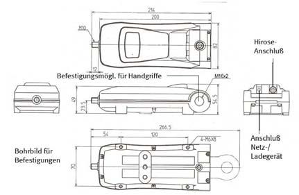
Deutsch............................................................................................ 3

English .......................................................................................... 19

Français ......................................................................................... 35

Espanol .......................................................................................... 50

Italiano .......................................................................................... 67

A.1 Declaration of Conformity..............................……………...........83

A.2 Calibration Confirmation ....................................................... 83
Vielen Dank, dass Sie sich für eines unserer hochwertigen Kraftmessgeräte entschieden haben. Lesen Sie diese
Bedienungsanleitung vor der Inbetriebnahme sorgfältig durch, damit Sie mit dem neu erworbenen Gerät sicher
umgehen sowie exakte und reproduzierbare Messungen vornehmen können, und um Schäden zu vermeiden.

1.0 Sicherheitshinweise
              Die Messzelle kann durch Überlastung der Messwelle beschädigt werden! Beachten Sie den
              maximalen Messbereich Ihres Gerätes! Der maximale Messbereich steht auf der Vorderseite Ihres
              Gerätes und auf dem rückseitigen Typenschild. Lassen Sie keine Kräfte seitlich oder radial auf die
              Welle einwirken. Benutzen Sie kein Werkzeug, um das Zubehör auf der Messwelle zu befestigen.

              Transportieren und lagern Sie das Gerät immer in dem dafür vorgesehenen Schutzkoffer. So
              verringern Sie das Risiko von Schäden durch ungewollte mechanische Einwirkungen, die ggf. zur
              Zerstörung der Messzelle führen können.

              Beachten Sie die für das Gerät zulässigen Umgebungsbedingungen. Das Gerät ist mit einer
              automatischen Temperaturkompensation für 0...40°C (max. 85%rF) ausgestattet. Setzen Sie das
              Gerät nur in diesem Bereich ein.

              Nutzen Sie für die Befestigung der Kraftmessgeräte in Prüfständen ausschließlich die dafür
              vorgesehenen Gewindebohrungen auf der Rückseite des Gerätes. Die M16x2 Gewinde für die
              abnehmbaren Handgriffe der Baureihe FMI-300/400 sind ausgelegt für eine maximale Kraft von
              2500N.

2.0 Vor Inbetriebnahme
2.1. Auspacken und Lieferumfang überprüfen
Die Kraftmessgeräte werden im Schutzkoffer geliefert, und insbesondere die Geräte für kleine Kräfte sollten
ausschließlich darin transportiert werden, da Stöße und starke Erschütterungen die Messzelle schädigen
können. Bitte überprüfen Sie den Inhalt, bevor Sie das Gerät in Betrieb nehmen. Die nachstehende Tabelle gibt
Ihnen eine Übersicht zum Lieferumfang und der Artikelnummern der Einzelteile, falls Sie diese zu einem
späteren Zeitpunkt nachbestellen möchten.

                                             FMI-100   FMI-200   FMI-210   FMI-220   FMI-230   FMI-300   FMI-400
 Schutzkoffer (FMI-910 für FMI-100 bis FMI
 230; FMI-911 für FMI-300 u. FMI-400)          z         z         z         z         z         z         z

 Basisgerät (siehe Typenschild mit
                                              FMI-      FMI-      FMI-      FMI-      FMI-      FMI-      FMI-
 Seriennummer und Angabe des
                                             100BU     200BU     200BU     220BU     220BU     300BU     400BU
 Messbereiches auf der Rückseite)
 Netz-Ladegerät (FMI-945)                      z         z         z         z         z         z          z
 Bedienungsanleitung (20025)                   z         z         z         z         z         z         z
 Haken (FMI-962 M4 / FMI-962 M6 / FMI-
                                             (-/z/-)   (z/z/-)   (z/z/-)   (z/z/-)   (z/z/-)   (-/-/z)   (-/-/z)
 962 M10)
 Spitze (FMI-965 M4 / FMI-965 M6 / FMI-
                                             (-/z/-)   (z/z/-)   (z/z/-)   (z/z/-)   (z/z/-)   (-/-/z)   (-/-/z)
 965 M10)
 Spatel (FMI-963 M4 / FMI-963 M6 / FMI-
                                             (-/z/-)   (z/z/-)   (z/z/-)   (z/z/-)   (z/z/-)   (-/-/z)   (-/-/z)
 963 M10)
 Flachkopf (FMI-961 M4 / FMI-961 M6 /
                                             (-/z/-)   (z/z/-)   (z/z/-)   (z/z/-)   (z/z/-)   (-/-/z)   (-/-/z)
 FMI-961 M10)
 Nutenkopf (FMI-964 M4 / FMI-964 M6 /
                                             (-/z/-)   (z/z/-)   (z/z/-)   (z/z/-)   (z/z/-)   (-/-/z)   (-/-/z)
 FMI-964 M10)
 Verlängerung (FMI-966 M4 / FMI-966 M6
                                             (-/z/-)   (z/z/-)   (z/z/-)   (z/z/-)   (z/z/-)   (-/-/z)   (-/-/z)
 / FMI-966 M10)

                                                             3
Hängeöse (20078) (-/z/-) (z/z/-) (z/z/-) (z/z/-) (z/z/-) (-/-/z) (-/-/z)
RS232C-Schnittstellenkabel (FMI-931 PC) - z z - z
USB-Schnittstellenkabel (FMI-931 USB) z z
Fmi_Connect Software (FMI-972) z z
Kalibrierprotokoll mit Daten (FMI-800) z z
Sollte, trotz unserer Ausgangskontrolle und wider Erwarten, ein Teil fehlen, informieren Sie bitte umgehend
Ihren Fachhändler oder uns unter service@alluris.de .
2.2. Batterie laden
Die Geräte sind mit wiederaufladbaren NiCd- oder NiMH-Zellen bestückt. Bevor Sie das Gerät zum ersten Mal
benutzen, laden Sie die interne Batterie vollständig auf. Im Display erscheint während des Ladevorganges das
Zeichen BAT; es erlischt, wenn die Batterie nach max. 12h vollständig geladen ist. Um eine möglichst lange
Lebensdauer der wiederaufladbaren Batterien zu erzielen (> 500 Ladezyklen), sollten Sie die Batterien immer
möglichst vollständig laden und entladen. Der Betrieb des Gerätes während des Ladevorganges ist möglich.
2.3. Batterien wechseln
Das Wechseln der Batterien sollte ausschließlich durch dafür qualifiziertes und autorisiertes Fachpersonal
durchgeführt werden. Bei Geräten, die zur regelmäßigen Kalibrierung bei Alluris eingeschickt werden, erfolgt
eine kostenfreie Überprüfung der Kapazität der wiederaufladbaren Batterien und ggf. ein kostenfreier
Austausch – außer Materialkosten – im Rahmen der Funktionsprüfung.
3.0 Übersicht FMI-100 | FMI-300
FMI-200 | FMI-210 | FMI-400
FMI-220 | FMI-230
3.1. FMI-100 ⏐ FMI-200 ⏐ FMI-210 ⏐ FMI-300 ⏐ FMI-400
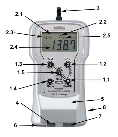
1 Bedientasten:
1.1 I/O-Taste zum Ein-/ und Ausschalten des Gerätes;
1.2 >>O1.3 PEAK-Taste zum Einstellen der Anzeige auf den aktuellen Messwert, oberen Spitzenwert der Druckkraft
oder Spitzenwert der Zugkraft, Schleppzeigerfunktion, sowie zum Aufrufen des maximalen und minimalen
Wertes der Messung;
1.4 MODE-Taste zur Einstellung der gewünschten Maßeinheit.
2 Display:
2.1 Anzeige der Batteriefunktionen;
2.2 Anzeige der Maßeinheiten und Basisfunktionen;
2.3 Anzeige der Betriebsart Peak;
2.4 4-stellige Messwertanzeige oder Anzeige der Funktionseinstellung.
3 Messwelle zur Aufnahme der Messadapter.
4 Steckdose für Netz-/Ladeadapter.
5 Befestigungsmöglichkeit für Fixierung im Prüfstand; Geräterückseite, Details siehe Maßzeichnung in
Kapitel 9.
6 Befestigungsmöglichkeit für Handgriffe; nur FMI-300 u. FMI-400.
7 Steckdose für Datenübertragung, Hirose HR12-10RC-10SDL; nicht bei FMI-100 und FMI-300.
8 Befestigungsmöglichkeit für Hängeöse.
3.2. FMI-220 | FMI-230
Bedienung, Display und Anschlüsse im wesentlichen wie zuvor beschrieben jedoch zusätzlich mit:
1.5 Mem-Taste zum Speichern und
Wiederaufrufen der gespeicherten Werte,
Aktivierung des Speichers.
2.5 Anzeige für das Arbeiten mit Grenzwerten.
6 Steckdose für USB-Anschluss.
54.0 Messungen durchführen FMI-100 | FMI-300
FMI-200 | FMI-210 | FMI-400
FMI-220 | FMI-230
4.1. Allgemeiner Hinweis
Da Kraftmessgeräte oft für zerstörende Prüfungen oder die Ermittlung von sicherheitsrelevanten
Grenzwerten eingesetzt werden, sollten Sie sich immer zunächst mit den daraus möglicherweise
resultierenden Gefahren, z.B. Scherben, plötzlicher Kraftwechsel, Quetschgefahr etc., vertraut
machen und ggf. Gegenmaßnahmen ergreifen.
Die interne Messzelle arbeitet bidirektional, also sowohl in Zug- als auch in Druckrichtung. Werksseitig ist das
Gerät so eingestellt, dass bei Druck auf die Messwelle ein positiver Kraftwert und bei Zug an der Messwelle ein
negativer Kraftwert angezeigt wird. Sie können diese Einstellung ändern; siehe Kapitel 8.2..
Das Gerät k0mpensiert die Nullpunkt-Drifts der Messzelle automatisch, sog. Tracking-Funktion. Diese Funktion
kann bei geringer Vorlast zu einer Nullpunktverschiebung führen, die das Messergebnis beeinflusst. Deshalb
lassen sich Werte unterhalb von ca. 0,5% des nominalen Kraftmessbereiches nicht darstellen; die Anzeige
springt immer wieder auf 0.000 zurück. Sie können diese Funktion deaktivieren; siehe Kapitel 8.3..
4.2. Anbringen der Messadapter für Druck- oder Zugkräfte
Wählen Sie den geeigneten Messadapter aus, um Druckkräfte ausüben zu können, oder benutzen Sie den
Haken, um Zugkräfte zu ermitteln. Die Verlängerungswelle sollten Sie nur benutzen, wenn die Zugänglichkeit
der Messstelle dies erfordert. Sonderzubehör für Ihre spezielle Applikation finden Sie außerdem im Internet
unter www.alluris.de .
4.3. Maßeinheit wählen
Mit Hilfe der MODE-Taste wählen Sie die gewünschte Maßeinheit. Mit jedem Drücken der Taste wechselt die
Anzeigeneinheit. Sie können die Anzeige jederzeit wechseln und die Werte umrechnen lassen.
4.4. Betriebsart wählen
Mit Hilfe der PEAK-Taste wählen sie die gewünschte Betriebsart, mit der Sie die Messung durchführen wollen.
Erscheint das Wort „Peak“ nicht auf dem Display, werden die aktuellen Werte sowohl in Druck- als auch in
Zugrichtung angezeigt. Erscheint das Wort „Peak“ ohne Vorzeichen auf dem Display, zeigt das Gerät nur den
Spitzenwert in Druckrichtung an. Erscheint das Wort „Peak“ mit „-„ Vorzeichen, zeigt das Gerät nur in
Zugrichtung an.
Die Spitzenwerte, Peak-Werte, werden bei allen drei Betriebsarten während der Messung erfasst und solange
gespeichert, bis das Gerät durch Tarieren/Nulljustierung mit der >>O4.5. Nulljustierung durchführen Führen Sie vor der Messung, eine Nulljustierung durch. Drücken Sie hierzu die >>OOOO
Schaltausgang gesetzt. Wird der untere Grenzwert größer als der oberer Grenzwert gesetzt, so entsteht ein
Fenster, in dem beide Zeichen angezeigt werden und beide Ausgänge geschaltet sind.

           Sowohl die Anzeige der Sonderzeichen als auch die Beschaltung des Ausganges beziehen sich auf
           den aktuell im Display angezeigten Wert ohne Berücksichtigung der Betriebsart oder der gewählten
           Maßeinheit. Sie müssen daher die Grenzwerte neu anpassen, wenn Sie die Maßeinheit wechseln.

5.4. Einstellen der Grenzwerte
Um Grenzwerte einzustellen, gehen Sie wie folgt vor.
        • Gerät ausschalten.
        • PEAK- und MEM-Taste drücken und festhalten während Sie das Gerät einschalten.
        • Warten Sie, bis im Display HI erscheint; lassen Sie dann die PEAK- und MEM-Taste los.
        • Drücken Sie die MODE-Taste. Die 4-stellige Messwertanzeige blinkt nun.
        • Wählen Sie mit der >>OOOO
zu 50 Datensätze hinterlegen.
Einzelwerte SinG Es werden die aktuell angezeigten Werte gespeichert, wenn die Speichertaste MEM
gedrückt wird. Es lassen sich bis zu 1000 Einzelwerte hinterlegen.
Kontinuierlich Cont Es werden alle Werte entsprechend der Display-Update-Zeit aufgezeichnet,
solange die Speicherfunktion aktiviert ist. Es lassen sich bis zu 1000 Werte
hinterlegen.
6.2. Einrichten der Speicherfunktion
Werkseitig sind die Geräte so eingestellt, dass der Standardspeicher Std genutzt wird. Um mit einer anderen
Speicherart zu arbeiten gehen Sie wie folgt vor:
• Gerät ausschalten.
• PEAK- und MEM-Taste drücken und festhalten.
• On/Off-Taste betätigen.
• Warten Sie, bis Display HI erscheint; lassen Sie dann die PEAK- und MEM-Taste los.
• Wählen Sie mit der PEAK-Taste die Funktion MEM.
• Wählen Sie danach mit der MODE-Taste die gewünschte Speicherart.
• Drücken Sie die MEM-Taste, um die Einstellung zu speichern.
6.3. Standardspeicher Std
6.3.1. Aufzeichnen einer Messreihe
Um dass Ergebnis einer Messreihe zu speichern, gehen Sie wie folgt vor:
• Drücken Sie die MEM-Taste bevor Sie die Messung durchführen. Das im Display blinkende „M“
zeigt an, dass Werte aufgezeichnet werden.
• Nehmen Sie die Messung vor.
• Nach erfolgter Messung drücken Sie erneut die MEM-Taste. Die Werte dieser Messung werden im
Gerät gespeichert.
Es werden jeweils der Maximal- und Minimalwert in Zug- und Druckrichtung, der Peakwert (+/-), und der letzte
Messwert im 1000Hz-Modus erfasst. Insgesamt lassen sich 50 Messreihen im Gerät speichern. Für jede
Messreihe wird eine aufsteigende Ordnungsnummer vergeben.
6.3.2. Anzeigen der gespeicherten Werte / Recall
Um den Ergebnisspeicher auszulesen und die Werte auf dem Display anzuzeigen gehen Sie wie folgt vor:
• Gerät ausschalten.
• MEM-Taste drücken und festhalten.
• On/Off-Taste betätigen.
• Warten Sie, bis im Display Std erscheint; lassen Sie dann die MEM-Taste los.
• Im Display blinkt nun die Nummer der letzten Messreihe abwechselnd mit dem zugehörigen
Messwert.
• Durch Drücken der MODE-Taste gelangen Sie zu den den einzelnen Statistikwerten.
• Durch Drücken der MEM-Taste gelangen Sie zu den Ergebnissen einer früheren Messreihe Werten,
mit einer niedriegeren Ordnungsnummer.
Es wird als erstes der zuletzt gespeicherte Wert angezeigt. Es werden dann (wiederholt) der maximaler und
minimaler Wert (+/-) und der Peakwert (+/-) der jeweiligen Messreihe angezeigt.
6.3.3. Löschen der gespeicherten Werte
Um die letzte Messreihe aus dem Ergebnisspeicher zu löschen oder den Speicher komplett zu löschen gehen
Sie wie folgt vor:
• Gerät ausschalten.
9• MEM-Taste drücken und festhalten.
• On/Off-Taste betätigen.
• Warten Sie, bis im Display Std erscheint.
• Lassen Sie dann die MEM-Taste los.
• Die jeweils letzte Messreihe mit der höchsten Ordnungsnummer wird mit einem kurzen Druck auf
die >>OO7.0 Datenübertragung FMI-200 | FMI-210 | FMI-400
FMI-220 | FMI-230
Bei den Kraftmessgeräten der Baureihen FMI-200/210/220/230 und FMI-400 können die Messdaten mit Hilfe
analoger und digitaler Ausgänge übertragen werden. Hierzu befindet sich an der Unterseite des Gerätes eine
Hirose Steckdose und, bei FMI-220 und FMI-230, eine zusätzliche USB-Schnittstelle. Die Farbangaben der
Einzeladern beziehen sich auf das passende Steckerkabel.
1 Analog OUT (-1...0...1 VDC) Braun
2 Analog Masse Rot
3 RS-232C RXD Orange
4 RS-232C GND Gelb
5 RS-232C DC Blau
6 RS-232C TXD Grau
7 NC Weiß
8 Schaltausgang 1 OC (30VDC 5mA) Schwarz
9 Schaltausgang 2 OC (30VDC 5mA) Rosa
10 Schaltausgang Masse Violett
7.1. Analogausgang
Der Analogausgang, -1...0...1 VDC, dient zur Übertragung an dafür geeignete Datenlogger, Recorder, Drucker
oder andere Aufzeichnungsgeräte. Die Justierung des Signals, Nullstellung, erfolgt durch Tarieren des Gerätes.
+/-1VDC stimmen überein, d.h. die Vorzeichen auf dem Display stimmen mit den Werten des Analogausgangs
überein. Um den Analogausgang zu nutzen, bestellen Sie bitte das entsprechende Kabel für Analogausgang,
Art.Nr.: FMI-931.
Spezifikation
Amplitude -1VDC / +1VDC
Signalerzeugung 12-bit D/A-Wandler
Signal Update 100 Hz
1000Hz bei FMI-220/FMI-230
7.2. Schaltausgang
Für jede Wirkrichtung steht hierfür jeweils 1 NPN-Transistor-Ausgang zur Verfügung. Für den Einsatz in
motorisierten Prüfständen bestellen Sie bitte das Kabel für Prüfstände, Art.Nr.: FMI-931TS.
7.2.1. Spezifikation des Schalters
Ausgang NPN Open Collector
Spannung 30VDC
Max. Strom 5 mA (Impedanz 10kOhm)
Schaltbild
117.2.2. Überlastausgang
Die Kraftmessgeräte sind so konstruiert, dass eine kurzzeitige Überlast von bis zu 200% des
Messbereichsendwertes zu keiner Schädigung der Messzelle führt. Aus Sicherheitsgründen wird jedoch bereits
beim Erreichen der 120% Marke ein Überlastsignal geschaltet, das insbesondere bei der Anwendung in
Prüfständen eine automatische Abschaltung des Prüfstands bewirken soll. Bei Geräten der Baureihe FMI-220
wird dieses Signal nur geschaltet, wenn die Grenzwertüberwachung nicht aktiviert ist.
7.2.3. Schaltausgang der Grenzwertüberwachung, nur FMI-220 und FMI-230
Wenn die Grenzwertüberwachung aktiviert ist, so erfolgt der Schalterausgang nach dem in Kapitel 5.3
beschriebenen Prinzip.
7.3 RS-232C Schnittstelle
Die RS-232C Schnittstelle ermöglicht die direkte Kommunikation mit einer geeigneten seriellen I/O-Karte eines
PCs. Hierzu müssen bei einer Übertragungsrate von max. 19200 Baud die Kommunikationsleitungen RXD, TXD
und GND angeschlossen sein. Das entsprechende Kabel mit der Art.Nr.: FMI-931PC ist im Lieferumfang der
Geräte mit Schnittstelle (nicht bei USB) enthalten.
7.3.1. Spezifikation der RS-232C Schnittstelle
Baud-Rate 2400, 4800, 9600 und 19200 (wählbar, siehe Einstellungen)
Datenlänge 8 bits
Stoppbit 1
Parität Keine
7.3.2. Protokollschlüssel
Eine Tabelle mit den Befehlsätzen für die Kommunikation zwischen dem Messgerät und einer externen
Datenverarbeitung ist auf unserer Website unter www.alluris.de verfügbar.
7.4. USB-Schnittstelle, nur FMI-220 und FMI-230
Die Datenübertragung via USB-Schnittstelle bieten sich insbesondere für Notebooks ohne serielle Schnittstelle
an. Ausserdem läßt sich mit der geeigneten Software (nicht im Lieferumfang enthalten) der Leistungsumfang
der Gerätebaureihe FMI-220/230 voll nutzen. Bitte lassen Sie das USB-Kabel nicht für längere Zeit an das
Kraftmessgerät angeschlossen. Auch wenn dieses ausgeschaltet ist, kann das Gerät weiterhin Energie
verbrauchen.
7.5 Software
Für die Datenübertragung in Standard
Microsoft Anwendungen bieten wir die
Software Fmi_Connect, Art. Nr. FMI-972,
ein Add-In für MS Excel, mit dem Daten
über die serielle Schnittstelle Ihres
Computers oder via USB Schnittstelle in
eine Tabelle übertragen werden können.
128.0 Sonderfunktionen FMI-100 | FMI-300
FMI-200 | FMI-210 | FMI-400
FMI-220 | FMI-230
8.1. Umschalten der Displayanzeige, Default: stehend
Die Umschaltung des Displays ist dann sinnvoll, wenn das Gerät zur
Zugkraftmessung oder in einem vertikalen Prüfstand eingesetzt wird. Hierzu gehen
Sie wie folgt vor:
• Gerät ausschalten.
• MODE-Taste drücken und festhalten.
• Gerät mit I/O-Taste einschalten und MODE Taste weiterhin festhalten.
• Warten Sie, bis die Displayanzeige umgeschaltet ist; lassen Sie dann die Mode-
Taste los.
Mit der gleichen Tastenkombination können Sie den ursprünglichen Zustand wieder herstellen.
8.2. Verändern des Vorzeichens bei Zug- und Druckprüfungen, Default: - bei Zug an der Messwelle
Die Veränderung des Vorzeichens ist dann sinnvoll, wenn das Gerät zur Zugkraftmessung einsetzt wird und die
Werte mit Hilfe der RS232C Schnittstelle automatisch ausgelesen werden.
• Gerät ausschalten.
• >>OOOOOO• Gerät ausschalten.
• >>OOOOOOO>OO9.0 Einsatz in Prüfständen FMI-100 | FMI-300
FMI-200 | FMI-210 | FMI-400
FMI-220 | FMI-230
Die Gehäuse der Kraftmessgeräte sind aus Al-Druckguss und mit Befestigungsmöglichkeiten für Prüfstände
versehen. Hierzu befinden sich auf der Rückseite der Geräte 4 Bohrungen für Schrauben mit metrischem
Gewinde.
Achten Sie auf die maximal zulässige Länge der
Schrauben. Längere Schrauben können zu
Verwindungen des Gehäuses führen, die das
Messergebnis beeinflussen oder das Gehäuse
zerstören.
Im Lieferumfang ist auch eine Öse enthalten,
die es ermöglicht, das Instrument in einer
entsprechenden Halterung aufzuhängen.
Befestigen Sie die Öse mit der dafür
vorgesehenen Kreuzschlitzschraube, die sich
auf der Rückseite des Gerätes unten in der
Mitte befindet.
Achten Sie auch bei der Montage an einen
Prüfstand darauf, dass die Krafteinwirkung auf
die Messwelle immer senkrecht erfolgen soll.
Die seitlichen Befestigungen
für die Handgriffe der
Baureihen FMI-300/400 sind
für maximal 2500N
ausgelegt.
Maßzeichnungen für den Einbau der Geräte in
Prüfständen finden Sie auch im Internet unter
www.alluris.de .
Manuelle und motorisierte Prüfstände mit denen linear geführte Hubbewegungen für die Zug- oder
Druckkraftprüfung durchgeführt werden können, sind eine sinnvolle Ergänzung zu einem Kraftmessgerät.
Hiermit lassen sich die Festigkeit von Materialverbindungen, die Betätigungskräfte von Bedienelementen oder
die Haftkraft von Verpackungen und Folien exakt und reproduzierbar ermitteln. Für eine
anwendungsspezifische Beratung stehen wir Ihnen gerne zur Verfügung. Produktinformationen zu unserern
Prüfständen finden Sie auch im Internet unter www.alluris.de.
1510.0 Technische Daten / Wartung / Kalibrierintervalle
FMI-100 FMI-200 FMI-210 FMI-220 FMI-230 FMI-300 FMI-400
Messbereich [N] 0-2
0-2 0-2 0-2
0-5
0-20 0-5 0-5 0-5
0-20 0-1000
0-50 0-20 0-20 0-20 0-1000
0-50 0-2500
0-200 0-50 0-50 0-50 0-2500
0-200 0-5000
0-500 0-200 0-200 0-200
0-500
0-500 0-500 0-500
0-1000
Auflösung der Anzeige [N] 0,001
0,001 0,001 0,001
0,001
0,01 0,001 0,001 0,001
0,01 1
0,01 0,01 0,01 0,01 1
0,01 1
0,1 0,01 0,01 0,01 1
0,1 1
0,1 0,1 0,1 0,1
0,1
0,1 0,1 0,1
1
Messfrequenz
1000 Hz
Anzeigefrequenz
1-20 Hz (einstellbar)
Netz-Ladegerät z z z z z z z
Bedienungsanleitung z z z z z z z
Zubehörsatz zur Krafteinleitung
(-/z/-) (z/z/-) (z/z/-) (z/z/-) (z/z/-) (-/-/z) (-/-/z)
(FMI-901M4 / FMI-901M6 / FMI-901M10)
Genauigkeit (F.S. +/- last significant digit) +/- +/- +/- +/- +/- +/- +/-
0,2% 0,2% 0,05% 0,2% 0,05% 0,2% 0,2%
Temperaturdrift (Tk relativ) pro K +/- +/- +/- +/- +/- +/- +/-
0,02% 0,02% 0,02% 0,02% 0,02% 0,02% 0,02%
Nullpunktdrift (Tk absolut) pro K +/- +/- +/- +/- +/- +/- +/-
0,02% 0,02% 0,02% 0,01% 0,01% 0,02% 0,02%
Tracking (Tk unterdrückt) automatische Kompensation
Überlastausgang z z z z z
RS 232 C Ausgang z z z z
z
100Hz | Baudrate einstellbar
USB Ausgang, 100Hz z z
Analogausgang z z z z z
Speicherfunktion z z
Grenzwert-Funktion z z
Temperaturbereich Betrieb 0° ... 40°C (max.. 85%rF)
Temperaturbereich Lagerung - 5° ... 45 (trocken lagern)
Schutzart IP 40
Gewicht 450 g 900 g
Abmessungen (L x B x H) 147 x 75 x 38 mm 214 x 82 x 55 mm
Die Geräte sind, mit Ausnahme der Verbrauchs- und Verschleißteile, wartungsfrei. Kraftmessgeräte sollten in
Abhängigkeit von Einsatzgebiet und Nutzungshäufigkeit regelmäßig, mindestens jedoch einmal jährlich,
überprüft und kalibriert werden. Unser Kalibrierservice (E-mail Adresse: service@alluris.de) umfasst eine
technische Überprüfung des Gerätes , die Kalibrierung – Werkskalibrierung – und, sofern notwendig, die
Justierung des Messbereiches.
1611.0 Sonstiges
11.1. Häufig gestellte Fragen (FAQ) – Problembehebung bei Störungen
Die Anzeige springt bei kleinen Kräften immer wieder auf 0,000 zurück!
Die automatische Temperaturkompensation, Tracking, ist eingeschaltet und bewirkt, dass die
Nullpunktdrift durch die Signalauswerte-Software unterdrückt wird. Sie können diese Funktion
abschalten; siehe Kapitel 8.3..
Bei mehrmaligem Messen im Bereich unterhalb von 0.5% des Messbereichs verschiebt sich der 0-Punkt!
Die automatische Temperaturkompensation, Tracking, ist eingeschaltet und bewirkt, dass die
Nullpunktdrift durch die Signalauswerte-Software unterdrückt wird. Sie können diese Funktion
abschalten; siehe Kapitel 8.3..
Das Display zeigt die Zahlen umgekehrt an!
Für den Einsatz in Prüfständen kann die Anzeigerichtung des Displays verändert werden; siehe
Kapitel 8.1..
Anzeige nur in Druck- oder Zugrichtung!
Wechseln Sie die Betriebsart durch Drücken der PEAK-Taste. Erscheint das Wort „Peak“ nicht auf dem
Display, werden die aktuellen Werte sowohl in Druck- als auch in Zugrichtung angezeigt; siehe
Kapitel 4.4..
Die Kraftwerte werden mit negativem Vorzeichen angezeigt!
In Abhängigkeit von Ihrer Anwendung können Sie das negative Vorzeichen entweder für Zug-
(werksseitige Einstellung) oder für Druckkräfte einstellen; siehe Kapitel 8.2..
Der angezeigte Peak-Wert ist größer als der Maximalwert!
Der Maximalwert entspricht dem Durchschnittswert der letzten Einzelmesswerte, wobei die Anzahl
der Einzelmesswerte abhängig ist von der Einstellung der Display-Update Zeit. Der Peak-Wert ist
demgegenüber der absolut höchste gemessen Einzelwert.
Das Gerät zeigt nicht an!
Überprüfen Sie den Ladezustand. Schließen Sie den zugehörigen Netzadapter an, und überprüfen
Sie die elektrischen Verbindungen. Falls Sie einen anderen Netzadapter verwenden, überprüfen Sie
die elektrischen Werte und die Polarität.
Die RS-232C Kommunikation ist gestört!
Überprüfen Sie die Verdrahtung des Verbindungskabels sowie die Übereinstimmung der Zuleitung
mit der Eingangsbelegung der PC-Karte.
Im Display erscheint eine der folgenden (Fehler)-Meldungen!
OVR ACHTUNG Überlast!! Die Messzelle kann geschädigt werden. Entfernen Sie die Last sofort
und überprüfen Sie das Gerät. Falls kein sinnvoller Messwert mehr angezeigt wird, muss
die Messzelle im Herstellerwerk ausgetauscht werden.
OV+ Krafteinwirkung von +120% des zulässigen Messbereichs. Reduzieren Sie die Last soweit,
bis das Gerät wieder einen zulässigen Wert anzeigt.
OV- Krafteinwirkung von -120% des zulässigen Messbereichs. Reduzieren Sie die Last soweit,
bis das Gerät wieder einen zulässigen Wert anzeigt.
OVP Überlast +!! Die Messzelle kann geschädigt werden. Entfernen Sie die Last sofort und
überprüfen Sie das Gerät. Falls kein sinnvoller Messwert mehr angezeigt wird, und das
Zeichen auch nach wiederholtem Ein- und Ausschalten angezeigt wird, muss die Messzelle
im Herstellerwerk ausgetauscht werden.
OVM Überlast -!! Die Messzelle kann geschädigt werden. Entfernen Sie die Last sofort und
überprüfen Sie das Gerät. Falls kein sinnvoller Messwert mehr angezeigt wird, und das
Zeichen auch nach wiederholtem Ein- und Ausschalten angezeigt wird, muss die Messzelle
im Herstellerwerk ausgetauscht werden.
ERR –3- Lesefehler des E²proms. Schalten Sie das Gerät aus und wieder ein. Sollte der Fehler dann
immer noch vorhanden sein, muss im Herstellerwerk der µ-Prozessor ausgetauscht
werden.
ERR –4- Schreibfehler des E²proms. Schalten Sie das Gerät aus und wieder ein. Sollte der Fehler
dann immer noch vorhanden sein, muss im Herstellerwerk der µ-Prozessor ausgetauscht
werden.
1711.2. Garantie
Wir gewähren auf alle Alluris Kraftmessgeräte eine erweiterte Garantie von 5 Jahren ab dem Datum der
Inbetriebnahme, sofern das Gerät unmittelbar nach Kauf bei uns registriert wurde und die Wartungs- und
Kalibrierintervalle eingehalten wurden. Ausgenommen hiervon sind Verbrauchs- und Verschleißteile, sowie
Schäden, die durch unsachgemäßen Einsatz des Gerätes entstehen. Ansonsten gelten die Garantieleistungen
wie in unseren AGBs vereinbart.
11.3. Produkt registrieren
Um automatisch über aktuelle Produktänderungen oder –Updates informiert zu werden und den vollen
Gewährleistungsanspruch zu genießen, senden Sie das beiliegende Formular an uns.
18Thank you for having chosen one of our high-quality digital force gauges. Please read this operation manual
thoroughly before using this instrument for the first time. Thus, you will be able to use your newly purchased
instrument accurately, to achieve accurate and reproducible results, and to avoid damages.
1.0 Safety precautions
The internal sensor (load measuring cell) can be damaged due to overload! Mind your gauge
model`s maximum measuring range! The maximum measuring range is stated on your
instrument`s front side and on the type label on the back. Do not apply side or radial forces to the
rigid measuring axle. Do not use any tools to screw measuring attachments onto the measuring
axle.
Always transport and store the instrument in its carrying case when not in use. Thus, you will
minimize the risk of damages caused by unmeant detrimental mechanical effects, which, as the
case may be, can destroy the internal sensor.
Take note of the correct environmental conditions. Do not operate or store the instrument in harsh
or dirty environments. The instrument is equipped with a temperature compensation for 0°...40°C.
Use the instrument in this temperature range only.
Please only use the threaded holes on the rear side of the instruments for test stand mounting.
The M16x2 threads are exclusively for the detachable handles of FMI-300/400 series instruments
and are laid out for a maximum load of 250 kg.
2.0 Before taking into operation
2.1. Unpacking and inspecting the delivery`s volume
The force gauges are delivered in carrying cases. Especially the instruments for small forces should be
exclusively transported therein as strokes and strong agitation may damage the measuring cell. Please inspect
the content before taking the instrument into operation. The following table provides an overview of the
delivery`s volume as well as the single components` order number in case you want to purchase them at a later
point in time.
FMI-100 FMI-200 FMI-210 FMI-220 FMI-230 FMI-300 FMI-400
Carrying case (FMI-910 for FMI-100 to
FMI 220; FMI-911 for FMI-300 and FMI- z z z z z z z
400)
Base model (see type plate with serial
FMI- FMI- FMI- FMI- FMI- FMI- FMI-
number and specification of measuring
100BU 200BU 200BU 220BU 230BU 300BU 400BU
range on the back)
Net-charger (FMI-945) z z z z z z z
Operation manual (20025) z z z z z z z
Hooks (FMI-962 M4 / FMI-962 M6 / FMI-
(-/z/-) (z/z/-) (z/z/-) (z/z/-) (z/z/-) (-/-/z) (-/-/z)
962 M10)
Cone point (FMI-965 M4 / FMI-965 M6 /
(-/z/-) (z/z/-) (z/z/-) (z/z/-) (z/z/-) (-/-/z) (-/-/z)
FMI-965 M10)
Chisel (FMI-963 M4 / FMI-963 M6 / FMI-
(-/z/-) (z/z/-) (z/z/-) (z/z/-) (z/z/-) (-/-/z) (-/-/z)
963 M10)
Slotted pan head (FMI-961 M4 / FMI-961
(-/z/-) (z/z/-) (z/z/-) (z/z/-) (z/z/-) (-/-/z) (-/-/z)
M6 / FMI-961 M10)
Groove head (FMI-964 M4 / FMI-964 M6
(-/z/-) (z/z/-) (z/z/-) (z/z/-) (z/z/-) (-/-/z) (-/-/z)
/ FMI-964 M10)
19Extension (FMI-966 M4 / FMI-966 M6 /
(-/z/-) (z/z/-) (z/z/-) (z/z/-) (z/z/-) (-/-/z) (-/-/z)
FMI-966 M10)
Hanger (20078) (-/z/-) (z/z/-) (z/z/-) (z/z/-) (z/z/-) (-/-/z) (-/-/z)
RS232C-interface cable (FMI-931 PC) - z z - z
USB-interface cable (FMI-931 USB) z z
Fmi_Connect Software (FMI-972) z z
Calibration protocol with data (FMI-800) z z
Should, albeit our issuing check, parts be missing, please refer to your stockist or to us at service@alluris.de
immediately.
2.2. Charging the battery
The gauges are provided with chargeable NiCd- and NiMH cells. Before using the instrument for the first time,
fully charge the internal battery. While charging, the battery indicator (BAT) is displayed; it will be off when the
battery is fully charged after 12h max.. In order to achieve a possibly long life cycle of the rechargable battery
(>500 charging cycles) you should re- and dis-charge them fully. The instrument can be used during the charging
process.
2.3. Changing the battery
The battery should be changed by authorised and qualified personnel only. The rechargeable batteries`
capacity of those instruments, which are sent to Alluris for checkup, is examined free of charge and, if
necessary, a free replacement (apart from material costs) is performed as part of the functional check.
3.0 Overview FMI-100 | FMI-300
FMI-200 | FMI-210 | FMI-400
FMI-220 | FMI-230
3.1. FMI-100 ⏐ FMI-200 ⏐ FMI-210 ⏐ FMI-300 ⏐ FMI-400
1 Operating keys:
1.1 I/O-button to turn instrument on and off;
1.2 >>O1.3 PEAK-button to set the display to the actual measuement value, upper peak value of compressive and
tensile force, drag indicator function, and to recall minimum and maximum value of done measurements;
1.4 MODE-button for selecting desired measurement unit;
2 Display:
2.1 Battery indicator;
2.2 Indicator for measuring units and base functions;
2.3 „Peak“ indicator;
2.6 4-digit main display, also displays functional settings.
3 Measuring axle for measuring attachments.
4 DC-Jack.
5 Mounting facility for test stand; at back of instrument, for details see graph in chapter 9.
6 Mounting facility for handles; only FMI-300 and FMI-400.
7 Outlet for data transmission, Hirose HR12-10RC-10SDL; not for FMI-100 and FMI-300.
8 Mounting facility for the hanger.
3.2. FMI-220 | FMI-230
Operation, display and plugs basically as described above, yet additionally with:
1.5 Mem-button for saving and recalling saved
values and activating storage, button 3.
2.5 Display for thresholds .
6 USB connector.
214.0 Conducting measurements FMI-100 | FMI-300
FMI-200 | FMI-210 | FMI-400
FMI-220 | FMI-230 | FMI-230
4.1. General advice
As gauges are often used in the scope of destruction-tests or for appraising security-relevant
thresholds you should always become familiar with the potentially resulting risks – broken
fragments, sudden change of force, crush risk – first and, if necessary, take counter actions.
The internal sensor functions bi-directional, i.e. in both directions, compression and tension. Factory-side, the
instrument is attuned to display a positive value in the case of compressive force applied at the measurement
axle, and a negative value in the case of tensile force. You may change this setting; see Chapter 8.2..
The instrument compensates zero-drifts automatically (tracking-function). In case of marginal preload, this
function can lead to a zero-shift, which may affect the measurement result. This is why values, which are below
approximately 0.5% of the nominal range of force measurement, are not shown; the display is switching back to
0.000. You may deactivate this function; see Chapter 8.3.
4.2. Mounting the adapters for compression and tension forces
Select the appropriate attachment for compression forces or use the hook to detect tension forces. The
extension rod should be used only if the accessibility of the object cannot be achieved without. Special
attachements for specific applications can be found on our homepage www.alluris.de.
Attach adapters by hand only. Do not use tools to screw adapters onto the instrument`s threaded
axle. Radial and side forces can damage the instrument. In order to monitor active forces it is
recommended to switch the instrument on while mounting an adapter.
4.3. Selecting the units of measurement
Using the MODE-button you may choose your preferred unit of measurement. Each time the button is pushed
the unit of measurement changes. You may always change the display and let values be converted.
4.4. Selecting the mode of operation
The PEAK-button allows you to select the mode of operation, in which you wish to conduct the measurement. If
the word “Peak” does not appear on the display, both compressive and tensile force values are shown. If the
word “Peak” appears without sign/prefix, the gauge displays peak values of compressive force, if “Peak” is
accompanied by a minus(“-“)-prefix, the instrument shows peak values of tensile force.
The peak values (Peak) are recorded during measurement in all modes of operation; they are stored until the
gauge is set back to zero by way of taring/zero-adjusting (»O«-button).
4.4.1. Regular mode
In the regular mode of operation the actual measured value is displayed. The actual measured value is the
average value of all single measured values since the display`s last update. Factory-made, the display update is
attuned to 3Hz. You may alter this setting; see Chapter 8.6.
4.4.2. Peak value indicator (Peak +) / drag indicator function
If the peak value indicator Peak+ is turned on, the display`s index resembles a drag indicator, which is dragged
further forward when values are rising. The measurement frequency in this mode is 1000Hz.
224.5. Zero-adjusting (taring) Before any force is applied, the instrument has to be customized to the application and be tared. Press the >>O
Both the display of the special characters and the setting of the outlet’s snubber circuit relate to the
            value shown on the display, without taking the mode of operation or the selected units into
            account. Therefore, you will need to adjust the threshold values if you wish to change the unit.

5.4. Setting threshold values
     •    Switch instrument off.
     •    Simultaneously press the PEAK- and the MEM-button and keep them pressed.
     •    Operate the On/Off-button.
     •    Wait until HI is displayed; then release the PEAK- and the MEM-button.
     •    Press the MODE-button. The 4-digit measurement value indicator is flashing now.
     •    The digits, which are to be set anew, can be selected with the »O«-button. The prefix/algebraic sign
          can be changed when all digits are flashing.
     •    The respective digit’s numeric value can be augmented with the MODE-button.
     •    Once the upper threshold value has been set, press the PEAK-button. The display will show LO.
     •    Just as described above with regard to the upper threshold value, use the »O«-button to determine
          the lower threshold value; use the MODE-button to change the value.
     •    Press the »O«-button to quit the threshold value setting function.

5.5. Modifying and deleting threshold values
To modify set threshold values act as described above. To delete values set all points zero. Thus, no signal for
automatic switch-off of a motorised test-stand will be available at the switching output.

5.6. Deactivating the threshold value monitoring function
To deactivate threshold value monitoring and to enable the switching outlet for overload signals go ahead
analogically to what has been described under 5.2. with regard to the activation of threshold value monitoring.
      •     Switch instrument off.
      •     Press and hold the »O«-button.
      •     Press the I/O-button.
      •     Select function F06 with the PEAK-button.
      •     Then, choose the overload outlet ovEr with the MODE-button.
      •     Save this setting by pressing the »O«-button.

6.0 Operating with memory                                                              FMI-220 | FMI-230
Gauges of the FMI-220 and FMI-230 series possess a data memory, in which values can be stored and recalled
at a later time. The values will be kept stored even if the gauge has been switched off temporarily.

6.1. General information
In general, there are three different modes of operation for storing measured values. Their operating mode is
described consecutively:

 Standard Std               Factory-side setting; all maximum and minimum values, all peak values of
                            compressive and tensile forces, and the displayed value in the case of deactivated
                            recording are being stored. Up to 50 data sets can be stored.
 Single value SinG          The actually displayed values are being stored by pressing the MEM-button. Up to
                            1000 values can be stored.
 Continuous data Cont       All displayed values are being stored as long as the memory function is activated.
                            Up to 1000 values can be stored.

                                                        24
6.2. Setting the memory mode of operation
• Switch instrument off.
• Press and hold the PEAK- and the MEM-button.
• Press the On/Off-button.
• Wait until HI is displayed, then release the PEAK- and the MEM-button.
• Select the function MEM with the PEAK-button.
• Then, choose the desired mode of memory with the MODE-button.
• Save the setting by pressing the »O«-button.
6.3. Standard memory (Std)
6.3.1. Recording measurement sequences
In order to save the results of a measurement series, please proceed as follows:
• Switch instrument off.
• Press the MEM-button before conducting the measurement. A blinking “M” will appear on the
display.
• Undertake the measurement.
• After done measurement, press again the MEM-button. The values of this measurement will be
stored.
Each time, the maximum and minimum value of compressive and tensile force, the Peak value (+/-) and the last
measured value in the 1000Hz mode are considered. Altogether, the instrument can store 50 measurement
sequences.
6.3.2. Recalling stored values
In order to read the stored values, please proceed as follows:
• Switch instrument off.
• Press and hold the MEM-button.
• Operate the On/Off-button.
• Wait until Std is displayed; then, release the MEM-button.
• The number of the last measurement sequence is blinking by turns with the corresponding
measurement value.
• You get to the maximum value etc by pressing the MODE-button.
• You get to the timely earlier measured values with a lower reference number by pressing the MEM-
button.
First of all, the last captured value is displayed. After that, this value`s maximum and minimum value (+/-) and
its Peak value (+/-) will be shown rotationally.
6.3.3. Deleting stored values
In order to delete the results of the last measurement series, or to empty the entire storage, please proceed as
follows:
• Switch off instrument.
• Press and hold the MEM-button.
• Operate the On/Off-button.
• Wait until Std is displayed.
• Then, release the MEM-button.
• Do not release button 3 until Std has appeared above on the display.
• The last measurement series with the highest reference number can be deleted by shortly pressing
the »O«-button once. The entire storage of measured values will be deleted when keeping the »O«-
button pressed until “nonE” appears on the display (approx. 5sec).
6.4. Single value memory (SinG)
6.4.1. Recording single measured values
Every measured value, which is visible on the display, is stored when pressing the MEM-button. This, for
example, can also be a PEAK value that is shown on the display after a measurement. The symbol M is shown
for a short moment on the display.
256.4.2. Recalling stored values
Proceed as described under 6.3.2.
• SIG is shown on the display; then, release the MEM-button.
• The reference number and its coherent measurement value are blinking in turn on the display.
• You get to the earlier saved measurement values with a lower reference number by pressing the
MEM-button.
• By repeatedly pressing the MODE-button, you get to the statistic values of all saved single values.
Then, rotationally, the maximum and minimum (+/-) value, the average and the standard deviation of
all stored values will be indicated.
6.4.3. Deleting stored values
Proceed as described under 6.3.3.
6.5. Continuous data memory (Cont)
6.5.1. Recording measurement sequences
Recording of measurement values starts by pressing the MEM-button; a blinking “M” appears in the display. By
operating the MEM-button once more, you stop the recording. The recording time (measurement rate) equals
the set display update time (default: 3Hz). Please also see chapter 8.6. When pressing the MEM-button anew,
the recording carries forward until the memory will be full with 1000 values.
6.5.2. Recalling stored values
At the beginning, proceed as described under 6.3.2..
• CNT is shown on the display; then, release the MEM-button.
• The reference number and its coherent measurement value are blinking in turn on the display.
• You get to the earlier saved measurement values with a lower reference number by pressing the
MEM-button.
• By repeatedly pressing the MODE-button, you get to the statistic values of all saved single values.
Then, rotationally, the maximum and minimum (+/-) value, the peak value (+/-), the average and the
standard deviation of all stored values will be indicated.
6.5.3. Deleting stored values
Proceed as described under 6.3.3..
7.0 Data transfer FMI-200 | FMI-210 | FMI-400
FMI-220 | FMI-230
The FMI-200/210/220/230 and FMI-400 force gauges feature a communication port for analogue and digital
outputs. A Hirose socket is located underneath the instrument, and, in the case of FMI-220 and FMI-230, an
additional USB-interface. The indication colours of the single conductors relate to the coherent connection
cable.
1 Analogue OUT (-1...0...1 VDC) Brown
2 Analogue Masse Red
3 RS-232C RXD Orange
4 RS-232C GND Yellow
5 RS-232C DC Blue
6 RS-232C TXD Grey
7 NC White
8 Overload tension OC (30VDC 5mA) Black
9 Overload compression OC (30VDC 5mA) Pink
10 GND Purple
267.1. Analogue Output
The analogue output (-1...0...1 VDC) can be used to serve appropriate data loggers, recorders, printers or other
monitoring equipment. The signal`s adjustment, zero-taring is carried out by taring the instrument. +/-1 VDC
corresponds to the maximum and minimum full scale (end of nominal measuring range); the algebraic signs
shown on the display correspond with the values of the analogue output. To make use of the analogue output,
the analogue cable (Order No.: FMI-931) should be ordered.
Specification
Amplitude -1VDC / +1VDC
Signal generator 12-bit D/A-Converter
Signal update 100 Hz
1000Hz in the case of FMI-220/FMI-230
7.2. Switching output
For each effective direction there is one NPN-transistor-outlet available. Please order the cable for test stands
(order no.: FMI-931TS) for application in motorised test stands.
7.2.1. Specification of the Output
Specification
Output NPN Open Collector
Voltage 30VDC
Max. power 5 mA (Impedance 10 kOhm)
Circuit drawing
7.2.2. Overload outlet
The force gauges are constructed in a way that short-time overloads of up to 200% of the measurement range’s
end value will not result in a damage of the internal sensor. For safety reasons, however, an overload signal
operates already when the 120% bench mark is reached. Especially in test stand applications, this is supposed
to attain an automatic shut-down of the test stand. In the case of instruments of the FMI-220 series, this signal
will only operate if the threshold value monitoring function is not activated.
7.2.3. Switching output of threshold value monitoring, only FMI-220 and FMI-230
If the threshold value monitoring function is activated the switching outlet will run according to the principle
described in Chapter 5.3..
7.3. RS-232C Interface
The RS-232C interface can be used for direct communication with a PC`s appropriate I/O-card. The minimum
requirement for data transfer up to 19200 baud is the connection with the RXD, TXD and GND communication
terminals. The applicable RS232-cable (Order No.: FMI-931PC) is included in the scope of supply of force gauges
with interfaces.
7.3.1. Specification of the RS-232C interface
Specification
Baud rate 2400, 4800; 9600 or 19200 (selectable, see general settings)
27Data length 8 bits
Stop bit 1
Parity None
7.3.2. Protocol codes
A table with the protocol codes for communication between measurement instrument and external data
processor is available at www.alluris.de .
7.4. USB Interface, only FMI-220 and FMI-230
Before connecting the force gauge via USB-interface to a PC in order to transfer data, please install the
optionally available software (order no.: FMI-972 USB). By that, you may transfer measurement results and
memorised values to Microsoft Exel and continue to process them.
Please do not leave the USB-cable connected to the force gauge for long. Even if it is switched off the
instrument may dissipate energy.
7.5 Software
We offer suitable software for transferring
the data to standard Microsoft
applications. The easy-to-use
Fmi_Connect (Part No. FMI-972), for
example, is an Add-In for MS Excel, which
allows to write the captured data directly
into your computer.
8.0 Special functions FMI-100 | FMI-300
FMI-200 | FMI-210 | FMI-400
FMI-220 | FMI-230
8.1. Reversing the display (Default: upright)
Reversing the display is recommended when the gauge is being used for tensile force
measurements or in a vertical test stand. Please proceed as follows:
• Switch instrument off.
• Press and hold MODE-button.
• Keep MODE-button pressed while switching instrument on with I/0-button.
• Wait until the Display is reversed, then release MODE-button.
You may return to the original setting by using the same buttons.
288.2. Changing the +/- prefix for compression and tension measurements ( Default: - with tension measurement)
Changing the prefix is recommended when the instrument is being used for tension measurements and values
are read automatically by means of the RS232C interface.
• Switch instrument off.
• Press and hold >>OOOOOOOOOOOO8.7. Altering the filter function, only FMI 220 and FMI-230
Using the filter function makes sense for measurements in a dynamic surrounding as well as in the case of
suddenly occurring force variations. There are three types of filter: 3 msec, 20 msec, 150 msec. The 3 msec
response time is recommended for dynamic applications with constantly occuring force variations, vibrations
and so on. An average of all values measured in the response time will be detected. The 150 msec response
time is recommended in the case of unwanted impulsively occurring changes, e.g. in the case of cylinders with
a big piston average, sudden impulses and so on. By choosing the low frequency, these abnormal changes will
be ignored (“filtered”).
• Switch instrument off.
• Press and hold >>OOO9.0 Application with test stands FMI-100 | FMI-300
FMI-200 | FMI-210 | FMI-400
FMI-220 |
The rugged aluminium dye cast housing of the force gauges enables applications on a test stand. 4 tap holes at
the rear of the housing can take up fixing screws with metrical threads.
The length of the screws should not exceed the
tape hole depth. Improper fastening (e.g. too
long screws) can distort the housing and lead
to inaccurate measuring results or damages.
Included in the scope of supply is a hanger,
which can be attached and fastened with a
Phillips screw to the rear of the instrument.
Moreover, in odrer to achieve accurate and
reproducible results, the forces should always
be applied perpendicular to the measuring axle
when the gauge is mounted on a test stand.
The fixings for the handles at
the side of the FMI-300/400
series` instruments is
designed for 2500N
maximum.
Dimensional drawings for mounting the
instruments to a test-stand can be found at
www.alluris.de.
For a force gauge, both manual and motorized test-stands are sound supplements, which linear strokes for
tensile and compressive force measurements can be conducted with. Thus, the stability of material
compounds, the operating force of control elements, or the adhesive force of packagings and films can be
detected accurately and reproducible. We are pleased to be at your command for custom-designed advices. In
the internet, at www.alluris.de, you will find product information about our test-stands.
3110.0 Technical data / maintenance / calibration
FMI-100 FMI-200 FMI-210 FMI-220 FMI-230 FMI-300 FMI-400
Measuring range [N] 0-2
0-2 0-2 0-2
0-5
0-20 0-5 0-5 0-5
0-20 0-1000
0-50 0-20 0-20 0-20 0-1000
0-50 0-2500
0-200 0-50 0-50 0-50 0-2500
0-200 0-5000
0-500 0-200 0-200 0-200
0-500
0-500 0-500 0-500
0-1000
Resolution [N] 0,001
0,001 0,001 0,001
0,001
0,01 0,001 0,001 0,001
0,01 1
0,01 0,01 0,01 0,01 1
0,01 1
0,1 0,01 0,01 0,01 1
0,1 1
0,1 0,1 0,1 0,1
0,1
0,1 0,1 0,1
1
Measuring frequency
1000 Hz
Display update time
1-20 Hz (selectable)
AC-Charger z z z z z z z
User manual z z z z z z z
Attachments (FMI-901 M4 / FMI-901 M6 /
(-/z/-) (z/z/-) (z/z/-) (z/z/-) (z/z/-) (-/-/z) (-/-/z)
FMI-901 M10)
Accuracy (F.S. +/- last significant digit) +/- +/- +/- +/- +/- +/- +/-
0,2% 0,2% 0,05% 0,2% 0,05% 0,2% 0,2%
Temperature drift (Tk relative) per K +/- +/- +/- +/- +/- +/- +/-
0,02% 0,02% 0,02% 0,02% 0,02% 0,02% 0,02%
Zero-point-drift (Tk absolute) per K +/- +/- +/- +/- +/- +/- +/-
0,02% 0,02% 0,02% 0,01% 0,01% 0,02% 0,02%
Tracking (Tk suppressed) automatic compensation
Overload signal z z z z z
RS 232 C interface z z z z
z
100Hz | Baud rate settable
USB 100Hz z z
Analogue signal -10V…0…10V) z z z z z
Memory function z z
Threshold value function (Limit) z z
Temperature range (operation) 0° ... 40° (max.. 85%rF)
Temperature range (storage) - 5° ... 45 (dry storage)
Protection Code IP 40
Weight 450 g 900 g
Size (L x W x H) 147 x 75 x 38 mm 214 x 82 x 55 mm
The gauges, apart from expendable and wearing parts, are maintenance-free. Depending on the area and
frequency of use, gauges should be regularly, namely at least once a year, be checked and calibrated. Our
calibration service (e-mail: service@alluris.de) includes a technical check of the instrument, calibration (factory
calibration) and, if necessary, adjustment of the measurement range.
3211.0 Other
11.1. Frequently asked questions (FAQ) – trouble shooting
In case of small forces the display always falls back to 0,000!
The automatic temperature compensation function (tracking) is switched on and causes the zero-
point drift being suppressed by the signal interpreting software. You may turn this function off; see
Chapter 8.3..
The zero-point shifts in the case of repeated measurements in the range below 0.5% of the measurement
scope!
The automatic temperature compensation function (tracking) is switched on and causes the zero-
point drift being suppressed by the signal interpreting software. You may turn this function off; see
Chapter 8.3..
The display shows numbers upside down!
The display direction can be changed for test stand application; see Chapter 8.1..
Display only in compressive or tensile force direction!
Change the mode of operation with the PEAk-button. When the word “Peak” does not appear on the
display, the actual values are shown both in compressive and tensile force direction; see Chapter
4.4..
Force values are depicted with negative prefix!
Depending on your usage you may set a negative prefix either for tensile forces (factory-side) or for
compressive forces; see Chapter 8.2..
The depicted Peak-value is higher than the maximum value!
The maximum value equals the average value of the last taken single values, whereas the amount of
single values depends on the set display update time. The peak value, in contrast, is the absolute
highest value measured.
Display fades out!
Check the remaining voltage. Plug in the AC-adaptor/charger and check the electric connections. In
case you are using a different adaptor, check the electricity values and the polarity.
RS-232C communication is disturbed!
Check the connection cable`s wiring and the compliance of wiring with input terminals of the PC-
card.
Indicated error codes:
OVR ATTENTION, overload! The internal sensor can be damaged. Immediately
remove the load and check the instrument. If no reasonable measuring value is
displayed anymore the internal sensor will need to be replaced at the
manufacturers`.
OV+ Overload of +120% related to full scale. Reduce the load until the instrument
indicates a value within the admissible measuring range.
OV- Overload of -120% related to full scale. Reduce the load until the instrument
indicates a value within the admissible measuring range.
OVP Overload +!! The load cell can be damaged. Remove the excessive load
immediately and check the instrument. If the indicated measuring values are
obviously untrue the load cell has to be changed by the manufacturer of the
instrument.
OVM Overload -!! The load cell can be damaged. Remove the excessive load
immediately and check the instrument. If the indicated measuring values are
obviously untrue the load cell has to be changed by the manufacturer of the
instrument.
ERR–3- Reading error of the E²proms. Switch the instrument off and turn it on again. If
the error still occurs the µ-processor might need to be changed by the
manufacturer.
ERR–4- Writing error of the E²proms. Switch the instrument off and turn it on again. If
the error still occurs the µ-processor might need to be changed by the
manufacturer.
33Sie können auch lesen