Fettabscheider EasyClean ground Standard, Direct NS 1, 2 und 4
←
→
Transkription von Seiteninhalten
Wenn Ihr Browser die Seite nicht korrekt rendert, bitte, lesen Sie den Inhalt der Seite unten
ANLEITUNG FÜR EINBAU, BEDIENUNG UND WARTUNG
Fettabscheider EasyClean ground DE
EN
Seite 1
Page 15
Standard, Direct NS 1, 2 und 4 FR
IT
Page 29
Pagina 43
NL Pagina 57
PL Strona 71
Ausführung nach EN 1825 Produktvorteile
Nach EN 1825-1
Einfache und schnelle
Montage
Geringes Gewicht
100% Beständigkeit
gegenüber aggressiven
Fettsäuren
Leichter Transport
Teleskopisches Aufsatz-
stück zur Anpassung an das
Bodenniveau
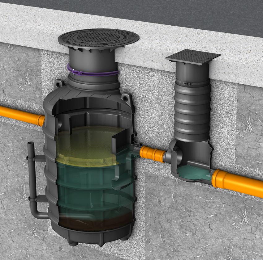
Abbildung zeigt Euro-Norm Abscheider EasyClean und Probenahmeschacht (Klasse D)
Techn. Änderungen vorbehalten
Installation Inbetriebnahme Einweisung
der Anlage wurde durchgeführt von Ihrem Fachbetrieb:
Name/Unterschrift Datum Ort Stempel Fachbetrieb
Stand 2021/05 Sach-Nr. 010-298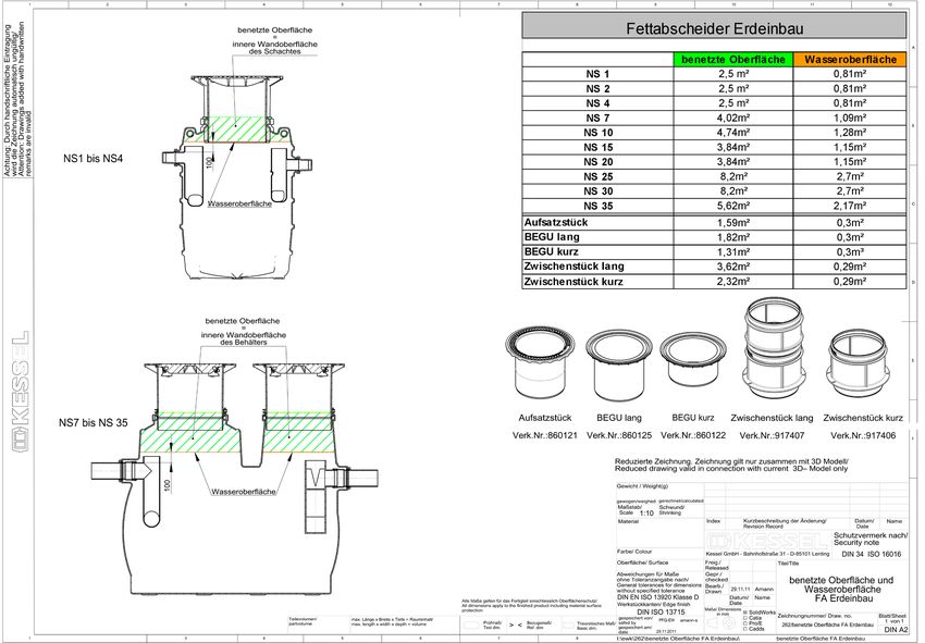
Inhaltsverzeichnis
Sicherheitshinweise                                                                                       3
1.1 Verwendung                                                                                            4
1.2 Anlagenbeschreibung                                                                                   4
1.3 Transport                                                                                             4
Einbau                                                                                                    4
2.1 Einbau des Behälters                                                                                  4
2.2 Einbau des Aufsatzstückes                                                                             4
2.4 Montage SonicControl                                                                                  5
2.5 Baugrube/Statik                                                                                       7
2.6 Anschließen der Entsorgungsleitung (nur Direct)                                                       7
Inbetriebnahme                                                                                            8
3.1 Anlage in Betriebsbereitschaft setzen                                                                 8
3.2 Einweisung / Übergabe                                                                                 8
Entsorgung                                                                                                9
4.1 Entleerungsintervalle                                                                                 9
4.2 Durchführung der Entsorgung                                                                           9
Wartung, Generalinspektion, Dichtheitsprüfung                                                            10
5.1 Wartung                                                                                              10
5.2 Generalinspektion                                                                                    10
5.3 Dichtheitsprüfung                                                                                    11
Ersatzteile und Zubehör                                                                                  12
Anlagenpass / Werksabnahme                                                                               14

Liebe Kundin, lieber Kunde,
als Premiumhersteller von innovativen Produkten für die Entwässerungstechnik bietet KESSEL
ganzheitliche Systemlösungen und kundenorientierten Service. Dabei stellen wir höchste Qualitätsstand-
ards und setzen konsequent auf Nachhaltigkeit - nicht nur bei der Herstellung unserer Produkte, sondern
auch im Hinblick auf den langfristigen Betrieb setzen wir uns dafür ein, dass Sie und Ihr Eigentum dauer-
haft geschützt sind.

Ihre KESSEL AG
Bahnhofstraße 31
85101 Lenting, Deutschland

Bei technischen Fragestellungen helfen Ihnen gerne unsere qualifizierten Servicepartner vor Ort weiter.
Ihren Ansprechpartner finden Sie unter: www.kessel.de/kundendienst

Bei Bedarf unterstützt unser Werkskundendienst mit Dienstleistungen wie Inbetriebnahme, Wartung oder
Generalinspektion in der gesamten DACH-Region, andere Länder auf Anfrage.
Informationen zur Abwicklung und Bestellung finden Sie unter: www.kessel.de/service/kundenservice.
html

                                                             2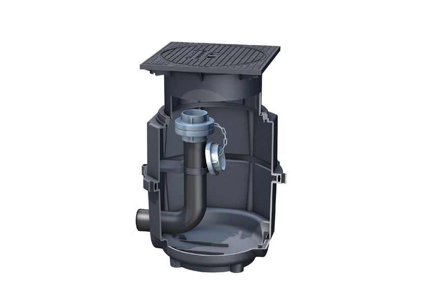
Sicherheitshinweise
                Das Personal für Einbau, Montage, Bedienung, Wartung und Reparatur muss die entspre-
                chende Qualifikation für diese Arbeiten aufweisen. Verantwortungsbereich, Zuständigkeit
                und die Überwachung des Personals müssen durch den Betreiber genau geregelt sein.

                Die Betriebssicherheit der gelieferten Anlage ist nur bei bestimmungsgemäßer Verwen-
                dung gewährleistet. Die Grenzwerte der technischen Daten dürfen auf keinen Fall über-
                schritten werden.

                Bei Einbau, Montage, Bedienung, Wartung und Reparatur der Anlage sind die Unfallver-
                hütungsvorschriften und die in Frage kommenden Normen und Richtlinien zu beachten!
                Dies sind u.a.:

                • Unfallverhütungsvorschriften
                   - Bauarbeiten BGV C22
                   - Abwassertechnische Anlagen GUV-V C5

                • Sicherheitsregeln für Arbeiten in umschlossenen Räumen von abwassertechnischen
                   Anlagen GUV-R 126

                • Umgang mit biologischen Arbeitsstoffen in abwassertechnischen Anlagen GUV-R 145

                • Richtlinien für Arbeiten in Behältern und engen Räumen GUV-R 113-004

                • Normen
                   - Baugruben und Gräben - Böschungen, Verbau, Arbeitsraumbreiten DIN 4124
                   - Verlegung und Prüfung von Abwasserleitungen und -kanälen DIN EN 1610

                • Arbeitshilfe für Sicherheit und Gesundheitsschutz in abwassertechnischen Anlagen

SPEZIFISCHE     • Gefahren durch Gase und Dämpfe wie Erstickungsgefahr, Vergiftungsgefahr
GEFÄHRDUNGEN!      und Explosionsgefahr in Schächten
                • Absturzgefahr
                • Ertrinkungsgefahr
                • Hohe physische und psychische Belastungen bei Arbeiten in tiefen, engen
                   oder dunklen Räumen

WARNUNG !       Bei Nichtbeachtung der Bedienungsanleitung können erhebliche Sachschäden, Körper-
                verletzungen oder tödliche Unfälle die Folge sein.

ACHTUNG !       Die Anlage stellt eine Komponente einer Gesamtanlage dar. Beachten Sie deshalb auch
                die Bedienungsanleitungen der Gesamtanlage und der einzelnen Komponenten. Bei jeder
                Montage, Wartung, Inspektion und Reparatur an einer der Komponenten ist immer die
                Gesamtanlage außer Betrieb zu setzen und gegen Wiederinbetriebnahme zu sichern.

                Umbau oder Veränderungen der Anlage sind nur in Absprache mit dem Hersteller zu
                tätigen. Originalersatzteile und vom Hersteller zugelassenes Zubehör dienen der Sicher-
                heit. Die Verwendung anderer Teile kann die Haftung für die daraus entstehenden Folgen
                aufheben.

                                          3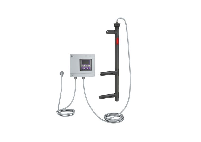
Sicherheitshinweise
1.1 Verwendung Fettabscheider selbst und einem integrierten Schlammfang.
Tierische und pflanzliche Öle und Fette dürfen nicht in die Die Version Direct enthält zusätzlich ein Direktentsorgungs-
öffentlichen Entsorgungsanlagen und in Gewässer gelei- rohr (links- oder rechtsseitg ausgeführt) und einen separa-
tet werden, da sie im erkalteten Zustand Querschnittsver- ten Probenahmeschacht.
engungen und Verstopfungen der Entsorgungsleitungen Die Fettabscheideanlagen zum Einbau ins Erdreich sind für
verursachen. Die DIN 1986 Teil 1 fordert die Rückhaltung gewünschte Einbautiefen und Abdeckungsklassen (A, B, D)
schädlicher Stoffe. Aus diesen Gründen sind Fettabschei- erhältlich.
deanlagen nach EN 1825 auszulegen, deren Inhalt entspre-
chend entsorgt werden muss. 1.3 Transport
Bei Heben via Seilzug oder Kran müssen die hierfür vor-
1.2 Anlagenbeschreibung gesehenen Hebeösen verwendet werden. Der Transport
Die Fettabscheider EasyClean ground Standard und Direct via Gabelstapler muss im orginalverpackten Zustand mit
sind für den Erdeinbau vorgesehen und bestehen aus dem Palette erfolgen.
Einbau
Die Fettabscheider zum Erdeinbau sollten außerhalb der mind. 1:50 vorgeschaltet werden. Der Übergang vom
Gebäude so nah wie möglich an den Abläufen eingebaut Fallrohr in die Beruhigungsstrecke sollte mit zwei 45°-
werden. Gegebenenfalls sind die Anschlussleitungen der Bögen ausgeführt werden. Damit verringert sich die
Zuläufe zum Fettabscheider wärmegedämmt oder beheizt Gefahr des Leersaugens von Siphons und Geruchs-
zu verlegen. Die Abdeckungen für die Belastungsklassen A verschlüssen. Der beruhigte Zulauf beugt außerdem
/ B, D sind geruchsdicht verschraubt und entsprechen der der Geruchs- und Schaumbildung im Abscheider vor.
EN 124. Die letzte Schicht wird mit 0/16-er Bruchschotter aufgefüllt
und verdichtet auf 97% Dpr.
2.1 Einbau des Behälters Das Aufsatzstück mit Abdeckplatte dient zugleich als Bau-
Vorgehensweise, Einbaubedingungen: zeitenschutz und dem Sicherstellen der Verkehrssicherheit.
➤ Der Baugrund muss waagrecht und eben sein, um
die Funktionsfähigkeit der Anlage zu gewährleisten. 2.2 Einbau des Aufsatzstückes
Außerdem muss der Baugrund eine ausreichende Achtung:
Tragfähigkeit aufweisen. Als Untergrund ist eine 25 - Aufsatzstücke dürfen erst nach vollständigem Einbau
30 cm dicke Schicht aus verdichtetem Bruchschotter (ausgehärteter Betonplatte) belastet werden.
(97% Dpr, 0-16mm) erforderlich. Darauf ist eine Sau- Das Aufsatzstück in die gewünschte Position bringen und
berkeitsschicht von 5-10 cm aufzubringen. mit Hilfe des Klemmringes fixieren. Die Feinjustierung auf
➤ Die wasserführenden Leitungen der Anlage sollten in die endgültige Höhe mit den Stellschrauben vornehmen.
frostfreier Tiefe ausgeführt werden. Dabei muss gewährleistet sein, dass auch die Zu- und Aus-
➤ Eine ausreichende Ableitung (Drainage) von Sicker- läufe später noch zu Reinigungszwecken zugänglich sind.
wasser ist bei wasserundurchlässigen Böden zwingend Sollte das Aufsatzstück zu tief in den Behälter eintauchen,
notwendig. muss das Aufsatzstück gegebenenfalls entsprechend ge-
➤ Die Baugrube muss 50 cm umlaufend um den Behälter kürzt werden.
ausgeführt werden. Bodenneigungen bis max. 5° können durch ein Schräg-
➤ Behälter bis zur Höhe des Auslaufes mit Wasser fül- stellen des Aufsatzstückes ausgeglichen werden. Bei der
len und auf undichte Stellen prüfen. Bei Austritt von Nenngröße NS 4 ist der kleinere Behälter zum Ausgleich der
Wasser ist zunächst die Verschraubung zu überprüfen Höhendifferenz auf Füße gestellt.
und gegebenenfalls nachzuziehen. Sollte das nicht den Hier muss beachtet werden, dass der dadurch entstehende
gewünschten Erfolg bringen, ist die Profildichtung auf Hohlraum zwischen Erdboden und Behälterboden gut un-
korrekten Sitz, Verschmutzungen oder Beschädigun- terfüllt und verdichtet wird (97% Dpr).
gen zu überprüfen und gegebenenfalls auszutauschen.
Dichtheitsprüfung des Aufsatzstückes
➤ Die seitliche Auffüllung muss mit Bruchschotter (0-
Behälter nach Einbauvorschrift einbauen. Bevor das Auf-
16mm) erfolgen. Die einzelnen Lagen sollten kleiner
satzstück eingerüttelt wird, bzw. die Betonschicht verlegt
als 30 cm sein. Für die Verdichtung ist ein Rüttler ein-
wird, ist die Dichtheit der Aufsatzstücke zu prüfen. Dazu
zusetzen.
den / die Behälter bis zur Oberkante des Aufsatzstückes mit
➤ Wenn bis zum Zu- und Auslauf der Anlage aufgefüllt
Wasser füllen und auf mögliche Undichtigkeiten überprüfen.
wurde, die Zu- und Auslaufleitungen anschließen. An-
schließend weiter auffüllen.
➤ Bei Fallrohren auf der Zulaufseite sollte eine Beruhi-
gungsstrecke von ca. 1 m Länge mit einem Gefälle von
4Einbau
2.3 Technische Daten und Hinweise • Be- und Entlüftung:
• Belastungsklasse A 15: Entsprechend der DIN EN 1825-2 müssen Fettabscheide
Einbau in Verkehrsflächen, die ausschließlich von Fußgän- anlagen, sowie deren Zu- und Auslaufleitungen, aus-
gern und Radfahrern benutzt werden. Ggf. das überstehen- reichend be- und entlüftet werden. Somit ist die Zulauf-
de Aufsatzstück mit dem Bodenbelag einrütteln. leitung als Lüftungsleitung bis über das Dach zu führen. Alle
• Belastungsklasse B 125: Anschlussleitungen von mehr als 5 m Länge sind gesondert
Einbau in Gehwege, Fußgängerbereiche, sowie PKW-Park- zu entlüften. Ist die Zulaufleitung länger als 10 m und keine
flächen und PKW-Parkdecks. gesondert entlüftete Anschlussleitung vorhanden, so ist die
• Belastungsklasse D 400: Zulaufleitung in Abscheidernähe mit einer zusätzlichen Lüf-
Bei Einbau in Fahrbahnen von Straßen, LKW-Parkflächen tungsleitung zu versehen.
und vergleichbar befestigten Verkehrsflächen muss eine
armierte Trageplatte (Lastverteilplatte) um das Aufsatzstück
betoniert werden. Ein für die spezifischen Dimensionen aus- 2.4 Montage SonicControl
gearbeiteter Bewehrungsplan ist auf Anfrage erhältlich. Im Zuge der Erdarbeiten ist ein PE-HD-Leerrohr DN 40
• Drückendes Grundwasser: (DA 50 mm) zu verlegen. Dieses ist an die vormontier-
Fettabscheider kann in drückendes Grundwasser bis 500 mm te Kabeldurchführung (Abbildungen unten) anzuschlie-
über Behältersohle verbaut werden. ßen. Die Verbindungsstrecke zwischen Abscheider und
• Anlagenvarianten: Schaltgerät ist möglichst kurz zu halten. Unnötige Rich-
Die Fettabscheideanlage EasyClean ground Standard ist tungsänderungen, insbesondere solche mit Abwinkelun-
überall dort geeignet, wo gen über 45°, sind zu vermeiden. Das Kabelleerrohr soll-
- die Geruchsbelästigung während der Entsorgung keine te ein stetiges Gefälle zum Abscheider aufweisen. Kon-
Rolle spielt, denswasserbildung innerhalb des Kabelleerohres kann
- das Einbringen der Saugleitung vom Entsorgungsfahr- durch einen luftdichten Abschluss des Leerrohres auf
zeug kein Problem darstellt. Seiten des Schaltgeräts minimiert werden. Für eventuelle
Die Fettabscheideanlage EasyClean ground Direct ist über- nachträgliche Kabelverlegungen ist ein Kabeldurchzugs-
all dort geeignet, wo draht eingelegt. Beim Einziehen des Kabels in das Kabel-
- über eine Entsorgungsleitung, z. B. eine Storz-B Kupp- leerrohr zum Schaltgerät muss die Kabelverschraubung
lung, angeschlossen werden soll, am Leerrohrverschluss fest angezogen werden.
-e ine räumliche Trennung des Entsorgungsvorgangs Anschließend ist die Überwurfmutter auf dem Rohrende
gewünscht wird. zu fixieren.
teleskopisches
Aufsatzstück
Mindesteinsteck-
tiefe 100 mm
Lippendichtung
DN 600
Behälterdom
Abb. zeigt EasyClean Standard NS 1-4
5Einbau
Fettabscheider EasyClean ground Standard nach DIN EN 1825-1
Schlammfang und Fettspeicher
Pos Nr. Bereiche
3
(1) Schlammfang
(2) Fettspeicher
(3) teleskopisches Aufsatzstück mit
Abdeckplatte
2
1
Maßzeichnung EasyClean Standard und Direct
875 T = Einbautiefe
630 OD = Außendurchmesser
b
100/110
DN/OD
T
DN/OD
100/110
DN 65
OD 75
a
h
h2
h1
Nenn- Abwasserinhalt
Gewicht DN a b h h1 h2
größe Schlammfang Abscheider Fettspeicher
1 111 kg 100 1380 1106 1050 540 610 140 l 230 l 70 l
2 120 kg 100 1380 1106 1300 790 860 200 l 370 l 120 l
4 130 kg 100 1380 1106 1550 1040 1110 400 l 370 l 160 l
6Einbau
2.5 Baugrube/Statik
Verdichteter Bruchschotter
30cm Sauberkeitsschicht (5-10 cm)
Schrittweise verdichteter Bruchschotter (pro
SchichtInbetriebnahme
3.1 Anlage in Betriebsbereitschaft setzen
Die Anlage ist vor der Zuführung von fetthaltigem Abwasser
vollständig zu reinigen (einschließlich Zu- und Ausläufen);
Fest- und Grobstoffe sind zu entfernen.
- Die gereinigte Anlage ist bis zum Anlagenüberlauf mit
kaltem Wasser zu füllen (dies entfällt natürlich, wenn die
Behälter vorher dichtgeprüft wurden und das Wasser nicht
abgepumpt wurde).
3.2 Einweisung / Übergabe
Nachdem der Verbau abgeschlossen ist, muss im Zuge der
Übergabe eine Dichtheitsprüfung des Behälters und der An-
schlüsse erfolgen. Vielfach schreiben die örtlichen Bestim-
mungen eine Generalinspekion mit technischer Prüfung von
Auslegung, sachgerechter Planung und ordnungsgemäßem
Verbau zwingend vor. In Deutschland muss die Generalin-
spektion nach DIN 4040-100 bei Erstinbetriebnahme und
danach alle 5 Jahre erfolgen.
Wir empfehlen die Übergabe / Generalinspektion im Zuge
der ersten Entsorgung des Abscheiders durchzuführen.
Nach Abschluss der Inspektion / Dichtheitsprüfung ist der
Abscheider betriebsbereit.
Alle Dienstleistungen zu Abscheidern können auch über
www.kessel.de/service/kundenservice.html bezogen wer-
den.
8Entsorgung
BITTE BEACHTEN SIE: 4.2 Durchführung der Entsorgung
- Diese Betriebsanleitung ist in der näheren Umgebung des Zum Lösen und Abziehen der Schrauben sowie zum Aus-
Abscheiders anzubringen. und Einheben der Schachtabdeckung mitgelieferte Aushe-
-
Der Entsorgungsvorgang ist genau nach Anweisung beschlüssel verwenden.
durchzuführen. - Schrauben lösen. Schachtabdeckung abnehmen.
- Die Entsorgung der Fettabscheideanlage ist nur von zuge - Mit Saugrüssel des Entsorgungsfahrzeuges Schlammfang
lassenen Entsorgungsunternehmen durchführen zu lassen. und Abscheidebehälter entleeren.
- Technische Änderungen vorbehalten! - Behälterwände reinigen, Fettreste entsorgen.
- Unfallverhütungsvorschriften beachten! - Behälter mit Wasser füllen.
- Bei Arbeiten am geöffneten Abscheider besteht RAUCH- - Dichtung der Schachtabdeckung säubern und prüfen.
VERBOT wegen möglicher Biogasbildung. Die erste Ent- - Schachtabdeckung verschließen.
sorgung ist innerhalb von 2-3 Wochen nach Inbetriebnah-
me durchzuführen.
4.1 Entleerungsintervalle:
Nach EN 1825 sind Schlammfänge und Abscheider, falls
nicht anders vorgeschrieben, vierzehntägig, mindestens
aber monatlich, zu leeren, zu reinigen und mit Frischwasser
wiederzubefüllen.
Achtung: Nur eine rechtzeitige Entsorgung der Anlage ge
währleistet eine richtige Funktion.
Aus diesem Grund sollte mit einem fachkundigen Unterneh-
men ein Entsorgungsvertrag abgeschlossen werden. Die
Entsorgungsarbeiten sind möglichst während der Zeiten
durchzuführen, in denen der Betrieb ruht. Bei geöffnetem
Abscheidebehälter ist mit einer Geruchsbelästigung zu
rechnen.
9Wartung, Generalinspektion, Dichtheitsprüfung
Das Kapitel Sicherheitshinweise ist zu beachten! elektrischen Einrichtungen, falls vorhanden
- Ausführung der Zulaufleitung der Abscheideanlage als
Vorgeschriebene persönliche Schutzausrüstung Lüftungsleitung über Dach
Bei Wartung der Anlage stets Schutzausrüstung - Vollständigkeit und Plausibilität der Aufzeichnungen im
verwenden: Betriebstagebuch
►►Schutzanzug - Nachweis der ordnungsgemäßen Entsorgung der entnom-
►►Schutzhandschuhe menen Inhaltsstoffe der Abscheideanlage
►►Gesichtsschutz - Vorhandensein und Vollständigkeit erforderlicher Zulas-
►►Auffanggurt sungen und Unterlagen (Genehmigungen, Entwässe-
rungspläne, Bedienungs- und Wartungsanleitungen)
5.1 Wartung Über die durchgeführte Überprüfung ist ein Prüfbericht
Die Abscheideanlage ist jährlich durch einen Sachkundi- unter Angabe eventueller Mängel zu erstellen. Wurden Män-
gen1) zu warten. gel festgestellt, sind diese unverzüglich zu beseitigen.
Der Behälter ist nach Inbetriebnahme nicht zu betreten, da
für Arbeiten in umschlossenen Räumen von abwassertech- 1)Als „sachkundig“ werden Personen des Betreibers oder
nischen Anlagen spezielle Sicherheitsvorkehrungen beauftragter Dritter angesehen, die aufgrund ihrer Ausbil-
(z. B. Freimessen und/oder Zwangsbelüftung, Sichern dung, ihrer Kenntnisse und ihrer durch praktische Tätigkeit
gegen Rückstau etc.) getroffen werden müssen. gewonnenen Erfahrungen sicherstellen, dass sie Bewertun-
Neben den Maßnahmen der Entsorgung sind dabei folgen- gen oder Prüfungen im jeweiligen Sachgebiet sachgerecht
de Arbeiten durchzuführen: durchführen.
- Vollständiges Abpumpen des Behälters, Reinigen des Zu-
und Auslaufes von Fettablagerungen. Die sachkundige Person kann die Sachkunde für Betrieb
-
Reinigung und Kontrolle der Innenwandflächen, des und Wartung von Abscheideanlagen auf einem Lehrgang
Schlammfanges und des Fettabscheiders. mit nachfolgender Vororteinweisung erwerben, den z. B.
- Funktionskontrolle der elektrischen Einrichtungen und In- die einschlägigen Hersteller, Berufsverbände, Handwerks-
stallationen, sofern vorhanden. kammern sowie die auf dem Gebiet der Abscheidetechnik
- Die durchgeführten Arbeiten und die Ergebnisse sind im tätigen Sachverständigenorganisationen anbieten.
Betriebstagebuch zu erfassen und zu bewerten.
2) Fachkundige Personen sind Mitarbeiter betreiberunab-
5.2 Generalinspektion hängiger Betriebe, Sachverständige oder sonstige Instituti-
Vor der Inbetriebnahme und danach in regelmäßigen Ab- onen, die nachweislich über die erforderlichen Fachkennt-
ständen von nicht länger als 5 Jahren ist die Abscheideanla- nisse für Betrieb, Wartung und Überprüfung von Abscheide-
ge, nach vorheriger vollständiger Entleerung und Reinigung, anlagen verfügen. Im Einzelfall können diese Prüfungen bei
durch einen Fachkundigen2) auf ihren ordnungsgemäßen größeren Betriebseinheiten auch von intern unabhängigen,
Zustand und sachgemäßen Betrieb zu prüfen. bezüglich ihres Aufgabengebietes nicht weisungsgebun-
Es müssen dabei mindestens folgende Punkte geprüft bzw. denenen Fachkundigen des Betreibers mit gleicher Qua-
erfasst werden: lifikation und gerätetechnischer Ausstattung durchgeführt
- Bemessung der Abscheideanlage werden.
- Baulicher Zustand und Dichtheit der Abscheideanlage
- Zustand der Innenwandflächen, der Einbauteile und der
10Wartung und Überprüfung (Generalinspektion)
5.3 Dichtheitsprüfung
benetzte Oberfläche Wasseroberfläche
NS 1 2,5 m2 0,81 m2
NS 2 2,5 m2 0,81 m2
NS 4 2,5 m2 0,81 m2
Aufsatzstück 1,59 m2 0,3 m2
BEGU lang 1,82 m2 0,3 m2
BEGU kurz 1,31 m2 0,3 m2
Verlängerungsstück Ø 600 3,62 m2 0,29 m2
Aufsatzstück BEGU lang BEGU kurz Verlängerungsstück
Art.Nr. 860121 Art.Nr. 860125 Art.Nr. 860122 Ø 600
Art.Nr. 917460
Artikel Art.Nr.
Generalinspektion Fettabscheider 917 411
Betriebstagebuch Fettabscheider 917 409
Dichtheit der Rohrstränge 917 417
11Ersatzteile und Zubehör
KESSEL-Probenahmeschacht Ø = 400
aus Kunststoff für Abscheideanlagen,
zum Einbau ins Erdreich
Zum Anschluss an die Ableitung von Abscheideanlagen,
leerlaufend.
Für Einbautiefe (T) 400-1300 mm (minimale Einbautiefe
erreichbar durch Ablängen).
Teleskopisches Aufsatzstück mit Klemmring, Abdeckung
Klasse A/B/D, geruchsdicht verschraubt, Absturzhöhe 120
mm.
Fabrikat: KESSEL
Einbautiefe Zu-/Auslauf Art.Nr.
T (mm) DN Klasse A Klasse B Klasse D
*400-1300 100/150 915 880 A 915880 B 915880 D
*400-1300 200 915 880 A-200 915880 B-200 915880 D-200
* Minimale Einbautiefe erreichbar durch Ablängen
Aufstockung um 600 mm mit
Verlängerungsstück Art.Nr. 915402
KESSEL-Verlängerungsstück
Für vertieften Einbau, Aufstockhöhe max. 600 mm (kürzbar).
Fabrikat: KESSEL
Ausführung Art.Nr.
Aufstockhöhe = 600 mm 915402
KESSEL-Probenahmeschacht LW 1000 aus Kunststoff, für
Abscheideanlagen, zum Einbau ins Erdreich
Zu- und Auslauf DN ... für Kunststoff-Rohre aus PE-HD
(nach DIN 19537); PVC-KG (nach DIN V19534); PP oder AS.
Einbautiefe (T) 1180-1630 mm (weitere Einbautiefen auf An-
frage), mit integrierten Steighilfen, mit teleskopisch höhenver-
stellbarem Aufsatzstück aus Kunststoff, mit Abdeckung Klasse
A/B, D nach DIN EN 124 aus GG, geruchsdicht verschlossen,
inkl. Aushebeschlüssel, Absturzhöhe 160 mm.
Fabrikat: KESSEL
Einbautiefe Zulauf passend Art.Nr.
T (mm) Auslauf zu Abscheider Klasse B Klasse D
1180-1630 DN 100 NS 1, 2 und 4 9151010 B 9151010 D
1180-1630 DN 150 NS 7 und 10 9151015 B 9151015 D
1180-1630 DN 200 NS 15, 20 und 9151020 B 9151020 D
Sonderanfertigung
12Ersatzteile und Zubehör
Entsorgungsschacht LW400 für den Anschluss der
Direktentsorgung:
Einbautiefe 630 mm bis 980 mm mit Flanschan-
schluss DN 65, PN 10 (Vorschweißbund und Los-
flansch) für Saugleitung mit Storz-B-Kupplung R 2
1/2" für Saugwagen.
KESSEL-Entsorgungsschacht
Art.Nr.
Belastungsklasse A/B
917422B
917 821
Belastungsklasse D 917422D
KESSEL-Fettschichtdickenmessgerät
Art.Nr.
SonicControl
917 821
13Mat. Bez.
Mat.Nr./Auftr.-Nr./Fert. Datum
Rev.Std./Werkstoff/Gewicht
Norm/Zulassung
Maße
Volumen
Schichtdicke
Bezeichnung 1
14
Bezeichnung 2
Anlagenpass / Werksabnahme
Anlagenpass / Werksabnahme
Die Anlage wurde vor Verlassen des Werks auf Vollständigkeit und Dichtheit überprüft.
Datum Name des PrüfersINSTRUCTIONS FOR INSTALLATION, OPERATION AND MAINTENANCE
Grease separator EasyClean ground
Standard, Direct NS 1, 2 and 4
Product
According to EN 1825
advantages
to EN 1825-1
Simple and fast
installation
Low weight
100% resistance
to aggressive fatty acids
Easy transport
Vertically adjustable upper
section for adjustment to the
ground level
Figure shows the EasyClean separator and sampling chamber (Class D) de-
signed to European standards
Subject to technical modifications
Installation Commissioning Briefing
of the system was carried out by your specialist company:
Name/Signature Date Location Stamp of specialist company
Dated 2021/05 Art. No. 010-298Table of Contents
Safety instructions 17
1.1 Use 18
1.2 System description 18
1.3 Transport 18
Installation 18
2.1 Installation of the tank 18
2.2 Installation of the upper section 18
2.4 SonicControl installation 19
2.5 Excavations/structural calculations 21
2.6 Connecting the disposal pipe (Direct separator only) 21
Commissioning 22
3.1 Getting the system ready for operation 22
3.2 Briefing/handover 22
Disposal 23
4.1 Emptying intervals: 23
4.2 Performing the disposal 23
Maintenance, general inspection, leak test 24
5.1 Maintenance 24
5.2 General inspection 24
5.3 Leak test 25
Spare parts and accessories 26
System passport / factory approval 28
Dear Customer,
As a premium manufacturer of innovative drainage products, KESSEL offers integrated system solutions
and customer-focussed service. In doing so, we set the highest quality standards and pay persistent
attention to sustainability - not only in the manufacture of our products, but also with regard to long-term
operation, we make every effort to ensure that you and your property are protected permanently.
Your KESSEL AG
Bahnhofstraße 31
85101 Lenting, Germany
Our qualified local service partners will be happy to help with any technical questions. Visit www.kessel.
de/kundendienst to find your contact.
If necessary, our Factory Customer Service department provides support with services such as commis-
sioning, maintenance or general inspection throughout the DACH region, other countries on request.
For information on processing and ordering, visit: www.kessel.de/service/kundenservice.html
16Safety instructions
The installation, assembly, operating, maintenance and repair personnel must have the
appropriate qualifications for this work. The owner/operating company must clearly define
the responsibilities, accountability and monitoring of the personnel.
The operational safety of the delivered system is only ensured if it is used as intended. The
limit values in the technical data must never be exceeded.
The accident prevention regulations and relevant standards, guidelines and directives
must be complied with during installation, assembly, operation, maintenance and repair
of the system.
These include:
• Accident prevention regulations
- Construction work BGV C22
- Wastewater systems GUV-V C5
• Safety rules for working in confined spaces of technical wastewater systems GUV-R
126
• Handling biological agents in technical wastewater systems GUV-R 145
• Guidelines for working in tanks and confined spaces GUV-R 113-004
• Standards
- Excavations and trenches - Slopes, planking and strutting breadths of working
spaces DIN 4124
- Construction and testing of drains and sewers EN 1610
• Good practice guide to health and safety in wastewater systems.
SPECIFIC • Risks due to gas and fumes, such as risk of suffocation, risk of poisoning and
HAZARDS! risk of explosion in chambers
• Risk of falling
• Risk of drowning
• High physical and mental stress when working in deep, confined or dark spac-
es
WARNING! Non-compliance with the operating instructions may result in considerable damage to
property, personal injuries or fatal accidents.
CAUTION! The system represents one component in a complete system. Please therefore also heed
the operating instructions for the complete system as well as the individual components.
During assembly, maintenance, inspection and repair work on one of the components, the
complete system must always be taken out of operation and secured against unintentional
starting.
Modifications or changes to the system may only be made in consultation with the man-
ufacturer. For safety reasons, use original spare parts and accessories approved by the
manufacturer. The use of other parts may void the liability for any consequences arising
thereof.
17Safety instructions
1.1 Use trap. The Direct version also includes an additional direct
Animal and vegetable fats, oil and grease (FOG) must not be disposal pipe (on the left or right-hand side) and a separate
discharged into public drainage systems and into bodies of sampling chamber.
water, as when they are cold they can cause constrictions The grease separators for underground installation are avail-
of cross-sections and blockages in the disposal pipes. DIN able for the required installation depths and cover classes
1986 Part 1 requires harmful substances to be retained. For (A, B, D).
these reasons, grease separators must be designed to EN
1825 and their contents must be disposed of accordingly. 1.3 Transport
If the separator is lifted by rope hoist or crane, the lifting
1.2 System description eyes provided for this purpose must be used. If transport-
The grease separators, EasyClean ground Standard and ed by forklift truck, the separator must be transported in
Direct, are intended for installation in the ground and con- its original packaged condition with pallet.
sist of the grease separator itself and an integrated sludge
Installation
The grease separators for underground installation should with two 45° bends. This reduces the risk of emptying
be installed outside the building as close to the drains as siphons (U-traps) and odour traps.
possible. If necessary, the inlet connection pipes to the The stilled inlet also prevents odour nuisance and
grease separator must be laid with thermal insulation or foaming in the separator.
thermal insulation with trace heating. The covers for load
classes A/B, D are screwed on odour-tight and conform to
EN 124. The final layer is filled with 0/16 crushed stone and is com-
pacted to 97% DPr.
2.1 Installation of the tank The upper section with cover plate also serves as a tempo-
Procedure, installation conditions: rary cover and ensures traffic safety.
➤ The ground must be horizontal and level
to ensure proper function of the system. 2.2 Installation of the upper section
In addition, the ground must be adequately load-bear- Attention:
ing. A 25 - 30 cm thick layer of compacted crushed Upper sections may only be subjected to a load follow-
stone (97% DPr, 0-16mm) is required as a subbase ing complete installation (cured concrete slab).
layer. This is then covered with a 5-10 cm thick blinding Place the upper section in the required position and fix in
layer. place using a clamping ring. The fine adjustment to the final
➤ The system pipes carrying water should be laid at a level is made using the adjusting screws. It must also be en-
frost-free depth. sured that the inlets and outlets are still accessible at a later
➤ Adequate discharge (drainage) of seepage water is ab- date for cleaning purposes. If the upper section extends too
solutely necessary for impermeable soils. far into the tank, it may be necessary to shorten the upper
➤ The excavations must include 50 cm working space all section accordingly.
around the tank. Ground slopes up to max. 5° can be compensated for by
➤ Fill the tank with water up to the level of the outlet and tilting the upper section. The smaller tank of nominal size
test for leaks. If water escapes, check the threaded NS 4 separators is placed on feet for levelling out the height
connection first and re-tighten it if necessary. If this difference.
does not solve the problem, make sure the profiled seal Here it must be noted that the resulting void between the
is fitted correctly, check for dirt or damage and replace ground and the bottom of the tank must be filled properly
if necessary. and compacted (97% DPr).
➤ The side space must be filled with crushed stone
Leak test of the upper section
(0-16mm). The individual layers should not exceed a
Install the tank according to the installation instructions.
height of 30 cm. A compaction machine must be used
Before the upper section is set in place or the concrete
for the compaction.
layer is laid, the leaktightness of the upper sections must
➤ If the backfill has been laid up to the system inlet and
be checked. To do this, fill the tank(s) with water up to the
outlet, connect the inlet and outlet pipes. Then contin-
upper edge of the upper section, and check for any leaks.
ue filling.
➤ In case of downpipes on the inlet side, a stilling sec-
tion of approx. 1 m with at least 1:50 gradient must be
laid upstream of the inlet connection. The transition
from downpipe to the stilling section should be made
18Installation
2.3 Technical data and notes • Ventilation:
• Load class A 15: According to EN 1825-2, grease separators and their inlet
Installation in traffic areas used only by pedestrians and and outlet pipes must be adequately ventilated. The inlet
cyclists. If necessary, vibrate the protruding upper section pipe must therefore be routed to above the roof as a venti-
with the flooring/ground surfacing. lation pipe (stack vent). All connection pipes longer than 5 m
• Load class B 125: must be ventilated separately. If the inlet pipe is longer than
Installation in footpaths, pedestrian areas, as well as car 10 m and there is no separately ventilated connection pipe
parking areas and car parking decks. available, the inlet pipe must be equipped with an additional
• Load class D 400: ventilation pipe near the separator.
A reinforced support slab (load distribution slab) must be
concreted around the upper section for installation in road
pavements, truck parking areas and comparably surfaced 2.4 SonicControl installation
traffic areas. A reinforcement plan produced for the specific A PE-HD conduit DN 40 (OD 50 mm) must be laid during
dimensions is available on request. the earthworks. This must be connected to the pre-in-
• Pressure-exerting groundwater: stalled cable passage (see figures below). The connec-
Grease separators can be installed in pressure-exerting tion distance between separator and control unit must
groundwater up to 500 mm above the tank invert. be kept as short as possible. Unnecessary changes in
• System variants: direction, particularly with angle offsets over 45°, must
The EasyClean ground Standard grease separator is suita- be avoided. The cable conduit should have a continuous
ble for use wherever gradient to the separator. Condensation inside the cable
- o dour nuisance does not play a role during emptying, conduit can be minimised by ensuring airtight connec-
- inserting the suction pipe of the disposal vehicle is not tion of the conduit at the control unit end. A cable pull
a problem. wire is inserted for possible subsequent cable laying.
The EasyClean ground Direct grease separator is suitable When pulling the cable into the conduit to the control
for use wherever unit, the cable gland must be tightened at the conduit
- the separator is to be connected via a disposal pipe, e.g. closure.
a Storz B coupling, The union nut must then be fixed on the end of the pipe.
- s patial separation of the disposal process is required.
Vertically adjustable
upper section
Minimum insertion
depth 100 mm
Lip seal
DN 600
Tank dome
Fig. shows EasyClean Standard NS 1-4
19Installation
Grease separator EasyClean ground Standard to EN 1825-1
Sludge trap and grease storage
Item No. Areas
3
(1) Sludge trap
(2) Grease storage
(3) Vertically adjustable upper section with
cover plate
2
1
Dimensioned drawing of EasyClean Standard and Direct
875 D = installation depth
630 OD = outside diameter
b
100/110
DN/OD
T
DN/OD
100/110
DN 65
OD 75
a
h
h2
h1
Nominal Wastewater contents
Weight DN a b h h1 h2
size Sludge trap Separator Grease storage
1 111 kg 100 1380 1106 1050 540 610 140 l 230 l 70 l
2 120 kg 100 1380 1106 1300 790 860 200 l 370 l 120 l
4 130 kg 100 1380 1106 1550 1040 1110 400 l 370 l 160 l
20Installation
2.5 Excavations/structural calculations
Compacted crushed stone
30cm Blinding layer (5-10 cm)
Layer-wise compacted crushed stone (each
layer < 30 cm)
3 Slope angle β (to DIN 4124)
30cm A load distribution slab is required for load
class D. A corresponding reinforcement plan
is available on request.
30cm
Note on the structural calculations:
The stability of the tank is only ensured for its self
30cm weight, transport and for the described instal-
lation in accordance with the intended use (e.g.
load class, road construction). Additional loads
ß
3 30cm from single or strip footings or other external
50cm actions must be avoided. Special measures may
2
4 have to be taken if these are to be expected.
1 30cm
Crushed stone, grading range 0/16, compacted to
97% DPr
Illustration shows NS 2
H
30°
a
Influence zone of adjacent foundations 2.6 Connecting the disposal pipe (Direct separator
Minimum distance from foundations (a = distance between only)
bottom edge of chamber and bottom edge of foundation a = The disposal pipe (in the left and right-hand version) may
ΔH x 1.73) not be dismantled. It must be continued vertically on site
In addition, the floor slab in the area of the chamber must with a PE pipe (DN 65) and must be connected to a Storz B
not be used for extensive load transfer from the building. coupling (available as an accessory). Horizontal pipes must
be laid with a gradient to the separator.
21Commissioning
3.1 Getting the system ready for operation
The system must be completely cleaned (including inlets
and outlets) before greasy wastewater is
drained into it; solids and coarse materials must be
removed.
- The cleaned system must be filled with cold water up to
the system overflow (this is, of course, not necessary if the
tank has been leak-tested beforehand and the water was
not pumped away).
3.2 Briefing/handover
After the installation has been completed, the tank and con-
nections must be leak tested as part of the handover. The
local provisions often require a general inspection with tech-
nical checking of the layout, proper design and installation.
In Germany, the general inspection to DIN 4040-100 must
be carried out at the time of the initial startup and then every
5 years.
We recommend that the handover/general inspection take
place as part of the first emptying of the separator. After the
inspection/leak test has been completed the separator is
ready for operation.
All separator services can also be purchased via www.kes-
sel.de/service/kundenservice.html.
22Disposal
PLEASE NOTE: 4.2 Performing the disposal
- These operating instructions must be displayed in the Use the removal key supplied to undo and remove the
immediate vicinity of the separator. screws and to lift in and out the cover.
- The emptying/disposal process must be carried out exact- - Undo the screws. Remove the cover.
ly according to the instructions. - Empty the sludge trap and separator tank using the suc-
- Only allow licensed waste collection companies to collect tion spout of the disposal vehicle.
the contents of the grease separator for disposal. - Clean the tank walls, remove and dispose of grease res-
- Subject to technical modifications! idues.
- Follow the accident prevention regulations! - Fill the tank with water.
- SMOKING IS PROHIBITED when working on or at the - Clean and check the seal of the cover.
opened separator due to potential biogas formation. The - Close the cover.
separator must be emptied for the first time within 2-3
weeks of putting into service (commissioning).
4.1 Emptying intervals:
According to EN 1825, unless specified otherwise, sludge
traps and separators must be emptied, cleaned and refilled
with fresh water at least once a month and, preferably, every
two weeks.
Attention: Correct functioning is only ensured if the separa-
tor is emptied in good time.
For this reason, a disposal (collection) contract should be
concluded with a licensed waste management company. If
possible, the emptying/collection work should be carried
out outside of business hours. Unpleasant odours must be
expected when the separator tank is opened.
23Maintenance, general inspection, leak test
Note and follow the "Safety Instructions” chapter! - The inlet pipe of the separator must be executed as a
ventilation pipe (stack vent) that terminates open to the
Specified personal protective equipment atmosphere above the roof
Always wear protective equipment during - Completeness and plausibility of the records in the log
maintenance of the system: book
►►Protective suit - Proof of proper disposal of the contents removed from
►►Protective gloves the separator
►►Face protection - Availability and completeness of all required approvals
►►Full body harness and documents (permits, drainage plans, operating and
maintenance instructions
5.1 Maintenance A test report must be drawn up for the inspection carried
The separator system must be serviced annually by a com- out, with details of any defects found. If defects are found,
petent expert/inspector1). they must be corrected immediately.
After commissioning the tank must not be entered, as work-
ing in the enclosed spaces of wastewater systems requires 1) The term “competent expert/inspector” is used to de-
special safety measures to be taken (e.g. testing the air to scribe employees of the owner/operating company or of
ensure it is safe and/or forced (mechanical) ventilation, pro- assigned third parties who, on account of their training,
tection against backflow, etc.). knowledge and practical experience, ensure that they carry
In addition to the disposal/emptying measures, the follow- out evaluations or tests/inspections properly in the respec-
ing work must also be carried out: tive field.
- Complete emptying of the tank by pumping out the tank
contents, cleaning the inlet and outlet to remove grease The competent expert/inspector can acquire the specific
deposits, knowledge for operation and maintenance of separators on
- Cleaning and inspection of the inside wall surfaces, the a course with subsequent on-site instruction. Such courses
sludge trap and the grease separator, are offered, for example, by the relevant manufacturers, the
- Functional test of the electrical equipment and installa- professional or industry associations, chambers of skilled
tions, if present. trades and organisations of experts/inspectors working in
- The work carried out and the results must be recorded and the field of separator technology.
evaluated in the log book.
2)Competent skilled persons are the employees of inde-
5.2 General inspection pendent companies, competent experts/inspectors or
After complete emptying and cleaning, the separator must other institutions, who verifiably have the necessary tech-
be inspected by a competent skilled person2) for proper nical knowledge required for the operation, maintenance
condition and operation before commissioning and then at and checking of separators. In individual cases, in larger
regular intervals of no longer than 5 years. company units these tests/inspections can also be carried
At least the following points must be checked and recorded: out by internal competent skilled persons of the operating
- Dimensioning of the separator company who are independent with regard to their area of
- Structural condition and leaktightness of the separator responsibility and are not bound by instructions, who have
- Condition of the internal walls, the installed parts and the the same qualifications and technical equipment available.
electrical equipment, if present.
24Maintenance and inspection (general inspection)
5.3 Leak test
Wet surface Water surface
NS 1 2.5 m2 0.81 m2
NS 2 2.5 m2 0.81 m2
NS 4 2.5 m2 0.81 m2
upper section 1.59 m2 0.3 m2
BEGU long 1.82 m2 0.3 m2
BEGU short 1.31 m2 0.3 m2
Extension section Ø 600 3.62 m2 0.29 m2
Upper section BEGU long BEGU short Extension section
Ø 600
Art. no. 860121 Art. no. 860125 Art. no. 860122 Art. no. 917460
Article Art. no.
General inspection of grease separators 917 411
Grease separator log book 917 409
Leaktightness of the pipe runs 917 417
25Spare parts and accessories
KESSEL sampling chamber Ø = 400
made of polymer, for separators,
for underground installation
For connection to the outlet pipe of separators,
empty running.
For installation depth (D) 400-1300 mm (minimum installation
depth can be achieved by cutting to the required length).
Vertically adjustable upper section with clamping ring, cover
class A/B/D, screwed odour-tight, backdrop height 120 mm.
Make: KESSEL
Installation Inlet/outlet Art. no.
depth D (mm) DN Class A Class B Class D
*400-1300 100/150 915 880 A 915880 B 915880 D
*400-1300 200 915 880 A-200 915880 B-200 915880 D-200
* Minimum installation depth can be achieved by
cutting to the required length
Extension by 600 mm with
extension section Art. no. 915402.
KESSEL extension section
For deeper installation, max. extension height 600 mm (can
be shortened).
Make: KESSEL
Version Art.No.
Extension height = 600 mm 915402
KESSEL sampling chamber LW 1000 made of polymer, for
separators, for underground installation
Inlet and outlet DN ... for polymer pipes made of PE-HD
(to DIN 19537); PVC-KG (to DIN V19534); PP or AS.
Installation depth (D) 1180-1630 mm (other installation depths
on request), with integrated access steps, with vertically
height-adjustable upper section made of polymer, with cover
class A/B, D to EN 124 made of grey iron (GG), closed odour-
tight, incl. removal key, backdrop height 160 mm.
Make: KESSEL
Installation Inlet Suitable Art. no.
depth D (mm) Outlet for the separator Class B Class D
1180-1630 DN 100 NS 1, 2 and 4 9151010 B 9151010 D
1180-1630 DN 150 NS 7 and 10 9151015 B 9151015 D
1180-1630 DN 200 NS 15, 20 and 9151020 B 9151020 D
Customised solution
26Spare parts and accessories
Disposal chamber LW400 for connection of the
Direct disposal installation depth 630 mm to 980
mm with flange connection DN 65, PN 10 (welding
neck and loose flange) for suction pipe with Storz-B
coupling R 2 1/2” for disposal vehicles.
KESSEL disposal chamber
Art. no.
Load class A/B
917422B
917 821
Load class D 917422D
KESSEL layer thickness
measuring device Art. no.
SonicControl
917 821
27Mat.-Description
Mat.-No./Order-No./Prod. Date
Ref.No./Material/Weight
EN/Approval
Dimensions
Volume
Layer thickness
Description 1
28
Description 2
16
Separator characteristics
System passport / factory approval
This unit has been checked for watertightness to be sure that it is fully operational before leaving the factory.
Date Name of examinerINSTRUCTIONS DE POSE, D'UTILISATION ET DE MAINTENANCE
Séparateur à graisses EasyClean ground
Standard, Direct NS 1, 2 et 4
Avantages du
Variante selon EN 1825
produit
Selon DIN EN 1825-1
Montage simple et
rapide
Faible poids
100 % résistant
aux acides gras
agressifs
Facile à transporter
Rehausse télescopique
d'adaptation au
niveau du sol
Sous réserve de modifications techniques
La figure montre le séparateur de norme européenne EasyClean et le dispositif d’échantillon-
nage (classe D)
Montage Mise en service Programmation
de votre système ont été effectués par votre revendeur spécialisé :
Nom / signature Date Lieu Cachet du revendeur spécialisé
Version 2021/05 Réf. 010-298Sommaire
Consignes de sécurité 31
1.1 Utilisation 32
1.2 Description du système 32
1.3 Transport 32
Pose 32
2.1 Montage de la cuve 32
2.2 Montage de la rehausse 32
2.4 Montage du SonicControl 33
2.5 Excavation/Statique 35
2.6 Raccordement de la conduite d’aération et de ventilation (Direct uniquement) 35
Mise en service 36
3.1 Mettre le système en ordre de marche 36
3.2 Instruction / réception 36
Évacuation 37
4.1 Intervalles de vidange : 37
4.2 Mise en œuvre de l’évacuation 37
Maintenance, inspection générale, essai d'étanchéité 38
5.1 Maintenance 38
5.2 Inspection générale 38
5.3 Essai d'étanchéité 39
Pièces de rechange et accessoires 40
Label du séparateur / Contrôle en usine 42
Chère cliente, cher client,
En qualité de producteur de pointe de produits novateurs dans le domaine de la technique d’assai-
nissement, KESSEL propose des réponses systématiques globales et un service orienté aux besoins
de la clientèle. Nous misons simultanément sur les normes de qualité les plus élevées et une durabilité
conséquente – non seulement lors de la fabrication de nos produits, mais également en vue d’une utilisa-
tion à long terme afin que vous, et vos biens, soient protégés durablement.
Votre KESSEL AG
Bahnhofstrasse 31
85101 Lenting, Allemagne
Nos partenaires qualifiés du service après-vente se feront un plaisir de répondre à vos questions tech-
niques sur site. Vous trouverez votre correspondant sur : www.kessel.de/kundendienst
Si nécessaire, notre propre SAV vous prête son assistance en matière de mise en service, de maintenance
ou d’inspection générale, en Allemagne, Autriche et en Suisse, et dans d’autres pays à la demande.
Toutes les informations de traitement et de commande sont à votre disposition sur : www.kessel.de/ser-
vice/kundenservice.html
30Consignes de sécurité
Le personnel affecté à la pose, au montage, à l'utilisation, à la maintenance et à la répa-
ration du système doit disposer d'une qualification appropriée à la mise en œuvre de ce
type de travaux. Il incombe à l'exploitant d’éviter toute ambiguïté et de régler les respon-
sabilités, les compétences et la surveillance du personnel.
La sécurité opérationnelle du système livré n'est garantie que lors d'une utilisation
conforme à l'usage prévu. Il est strictement interdit de dépasser les valeurs limites des
caractéristiques techniques.
Toujours respecter les directives de prévention des accidents, ainsi que les normes et
directives s'y rapportant lors de la pose, du montage, de l'utilisation, de la maintenance
et de la réparation du système.
Il s'agit en particulier de ce qui suit :
• Directives de prévention des accidents
- Travaux de construction BGV C22
- Installations techniques d'évacuation des eaux usées GUV-V C5
• Règles de sécurité relatives aux travaux dans les espaces confinés des installations
techniques d'évacuation des eaux usées GUV-R 126
• Manipulation de substances et d'agents biologiques dans des installations techniques
d'évacuation des eaux usées GUV-R 145
• Directives relatives aux travaux exécutés à l'intérieur des cuves et dans des espaces
exigus GUV-R 113-004
• Normes
- Fouilles et fossés - Talus, coffrage, largeur de l'espace de travail DIN 4124
- Pose et contrôle des tuyaux d'évacuation et canalisations DIN EN 1610
• Aide-mémoire en matière de sécurité et de santé dans des installations techniques
d'évacuation des eaux usées
DANGERS • Risques dus aux gaz et vapeurs tels que les dangers d'asphyxie, d'intoxication et d'ex-
SPÉCIFIQUES ! plosion dans les regards
• Risque de chute
• Risque de noyade
• Désagréments physiques et psychiques élevés lors de travaux dans des espaces pro-
fonds, étroits ou sombres
AVERTISSEMENT ! Le non-respect des instructions d'utilisation risque de provoquer des dommages maté-
riels considérables, des blessures, voire des accidents mortels.
ATTENTION ! Le système est un composant d'une installation complète. Il est donc indispensable d'ob-
server également les notices d'utilisation et instructions de service de l'installation com-
plète et des composants individuels. Toujours mettre l'installation complète hors service
lors de travaux de montage, de maintenance, d'inspection et de réparation sur l'un des
composants et la bloquer contre une remise en marche.
Les transformations ou modifications du système posent pour condition de disposer de
l'accord du fabricant. Les pièces de rechange d'origine et accessoires homologués par le
fabricant garantissent et accroissent la sécurité. L'utilisation d'autres pièces risque d'an-
nuler la responsabilité du fabricant pour les conséquences en résultant.
31Consignes de sécurité
1.1 Utilisation le séparateur à graisses en soi et un débourbeur intégré.
Il est interdit d'éliminer les huiles animales et végétales ainsi La version Direct comporte en supplément un tuyau de
que les graisses via les usines publiques de traitement des vidange directe (exécution côté gauche ou droit) et un dis-
déchets et de les jeter dans les égouts, car une fois refroi- positif d’échantillonnage séparé.
dies, elles causent des rétrécissements et des bouchons qui Les séparateurs à graisses pour la pose enterrée existent
engorgent les canalisations. De plus, la partie 1 de la norme pour les profondeurs de pose et classes de charge (A, B,
DIN 1986 prescrit le confinement des matières nocives. D) souhaitées.
C'est aussi pour ces raisons que la norme EN 1825 prévoit 1.3 Transport
des séparateurs à graisses dont les déchets devront être Pour soulever le dispositif à l’aide d'un treuil ou d'une
éliminés en conséquence. grue, il est nécessaire d’utiliser les anneaux de levage
1.2 Description du système prévus à cet effet. Le transport par chariot-élévateur doit
Les séparateurs à graisses EasyClean ground Standard ou se faire avec le dispositif dans son emballage d’origine sur
Direct sont conçus pour la pose enterrée et comprennent palette.
Pose
Les séparateurs à graisses pour une pose enterrée doivent que le système est remblayé jusqu’au niveau de l’ar-
être placés à l'extérieur des bâtiments, aussi près que pos- rivée et de la sortie. Poursuivre le remblayage par la
sible des écoulements. Si nécessaire, il convient de poser suite.
les conduites de raccordement des arrivées de produits ➤ Dans le cas de tuyaux de descente côté arrivée, il est
dans le séparateur à graisses sous une forme isolée ther- nécessaire de prévoir en amont une section de sta-
miquement ou chauffée. Les couvercles de recouvrement bilisation d'une longueur d’env. 1 m avec une pente
des classes de charge A / B et D sont vissés de manière à d'au moins 1:50. Le passage du tuyau de descente à
être hermétiques aux odeurs, et sont conformes à la norme la section de stabilisation doit être exécuté avec deux
EN 124. coudes de 45°. Cela réduit ainsi le risque de vidange
des siphons par aspiration. L'arrivée anti-remous pré-
2.1 Montage de la cuve vient également la formation d'odeur et de mousse
Procédure, conditions de montage : dans le séparateur.
➤ Le terrain de fondation doit être horizontal et plan Remblayer la dernière couche avec du gravier concassé
pour garantir le bon fonctionnement du système. d’une granulométrie de 0/16 et compacter avec une densité
Par ailleurs, le terrain de fondation doit disposer d’une Proctor de 97 %.
La rehausse avec couvercle de protection sert simultané-
capacité de charge suffisante. Il convient de prévoir, ment de couvercle de protection de chantier et garantit la
comme couche de base, une couche composée de sécurité du trafic.
gravier concassé compacté d’une granulométrie de
0-16 mm (densité Proctor de 97 %) d’une épaisseur de 2.2 Montage de la rehausse
25 à 30 cm. Une couche de mise à niveau de 5-10 cm Attention :
est posée ensuite sur celle-ci. Ne pas mettre les rehausses en charge avant l’achève-
➤ Les conduites d’eau du système doivent être posées à ment de la pose (dalle béton complètement durcie).
une profondeur hors gel. Amener la rehausse à la position souhaitée et la fixer avec
➤ Il est impératif de prévoir une évacuation suffisante l’anneau serrant. Utiliser ensuite les vis d'arrêt pour l'ajus-
(drainage) des eaux d'infiltration dans le cas de sols tage de précision à la hauteur définitive. Veiller, en parti-
imperméables. culier, à ce que les conduites d’arrivée et de sortie restent
➤ L’excavation doit être réalisée 50 cm autour de la cuve. accessibles pour le nettoyage. Il se pourrait que vous deviez
➤ Remplir la cuve d’eau jusqu’à hauteur de la sortie et vé- raccourcir la rehausse à la dimension requise si elle s’insère
rifier l’absence de fuites. En cas de fuites d’eau, vérifier trop profondément dans la cuve.
d’abord les raccords à vis et les resserrer si nécessaire. Une position inclinée de la rehausse permet de compenser
Pour autant que cette mesure ne donne pas le résultat des inclinaisons du sol de jusqu'à 5°. La cuve plus petite
souhaité, vérifier l’ajustement correct et l’absence de de la taille nominale NS 4 est placée sur des pieds pour
saletés ou d’endommagements du joint profilé, et le compenser la différence de hauteur.
remplacer si nécessaire. Il est particulièrement important de bien combler l’espace
➤ Remblayer les parties latérales avec du gravier concas- vide entre le sol et le fond de la cuve et de le compacter
sé (0-16 mm). Les couches ne devraient pas dépasser (densité Proctor de 97 %).
une épaisseur de 30 cm. Utiliser un vibrateur pour le
compactage.
➤ Raccorder les conduites d’arrivée et d’écoulement dès
32Sie können auch lesen